1
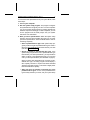
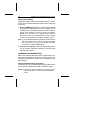
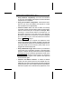
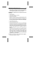
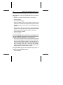
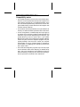
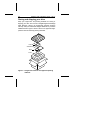
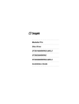
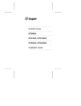
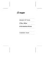
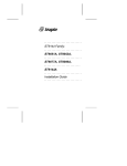
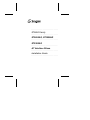
.......................... ST9655 Family .......................... ST9655AG, ST9550AG .......................... ST9385AG .......................... AT Interface Drives .......................... Installation Guide .......................... Contents Read before you begin... . . . . . . . . . . . . . . . . . . 1 Configuring the drive . . . . . . . . . . . . . . . . . . . . 2 Attaching cables . . . . . . . . . . . . . . . . . . . . . . . 2 Mounting the drive . . . . . . . . . . . . . . . . . . . . .4 Configuring your computer . . . . . . . . . . . . . . . . . 6 Formatting and partitioning the drive . . . . . . . . . . . 9 Installation troubleshooting . . . . . . . . . . . . . . . 10 Compatibility notes . . . . . . . . . . . . . . . . . . . . 17 Technical support services . . . . . . . . . . . . . . . . 18 Storing and shipping your drive . . . . . . . . . . . . . 20 © 1994 Seagate Technology, Inc. All rights reserved Publication Number: 36286-001, Rev. A October 1994 Seagate, Seagate Technology and the Seagate logo are registered trademarks of Seagate Technology, Inc. SeaFAX, SeaFONE, SeaBOARD and SeaTDD are trademarks of Seagate Technology, Inc. Other product names are registered trademarks or trademarks of their owners. Seagate reserves the right to change, without notice, product offerings or specifications. No part of this publication may be reproduced in any form without written permission from Seagate Technology, Inc. ST9655 Family Installation Guide, Rev. A 1 Read before you begin... Application. Your drive is designed for IBM AT and compatible personal computers, particularly laptop and notebook models. Warning. Turn off the computer (and, if you have a notebook or laptop computer, remove the battery) before you open the case or touch any internal components. Caution. Special training or tools may be needed to service laptop and notebook computers. Opening the case may void your warranty. Review the terms and conditions of your warranty before opening the case. Static discharge. Observe the following precautions: • Before handling any components, put on a grounded wrist strap. • Use antistatic padding on all work surfaces. • Avoid static-inducing carpeted areas. • Keep the drive in its static-shielded bag until you are ready to complete the installation. Do not attach any cables to the drive while it is in its static-shielded bag. • Handle the drive by its edges or frame. • Do not touch the I/O connector pins or the circuit board. Drive handling. The drive is extremely fragile—handle it with care. Do not attach labels to any part of the drive. Inspection. After you are familiar with the handling precautions listed above, inspect the drive. If it appears to be damaged, call your distributor or dealer immediately. Warranty. See your authorized Seagate® distributor or dealer. Maintenance and repair. Seagate drives do not require maintenance. The head/disc assembly is sealed; if you break the seal, 2 ST9655 Family Installation Guide, Rev. A you void the warranty. Seagate customer service centers are the only facilities authorized to repair Seagate drives. Seagate does not sanction any third-party repair facilities. Configuring the drive 1. Put on a grounded wrist strap. Wear the grounded wrist strap throughout the installation procedure. 2. Install master/slave jumpers. In a two-drive system, you need to designate one drive as the master, or drive 0, and the other drive as the slave, or drive 1. To do this, install the master/slave jumpers as shown in Figure 1. In a one-drive system, configure the drive as a master (no jumpers installed). Alternatively, you can configure the drive as a master or slave using the cable select option. To use this option, the host system and both drives must support cable select. Cable selection requires a special daisy-chain cable that grounds pin 28 (CSEL) on one of its two drive connectors. If you attach the drive to the grounded CSEL connector, it becomes a master. If you attach the drive to the ungrounded CSEL connector, it becomes a slave. To configure an ST9655 family drive for cable select, install both master/slave jumpers, as shown in Figure 1. Attaching cables This drive is designed for a host computer that supplies interface signals and +5V power through a single 44-pin connector and cable. If your computer has a fixed connector that attaches directly to the drive, skip ahead to the following section, “Mounting the drive.” Otherwise, perform the steps listed on page 4. ST9655 Family Installation Guide, Rev. A Note. Drive is shown with circuit board up. Master/slave Pin 1 configuration jumpers Pin 20 removed for keying Circuit board B A D C Drive is master; slave may be detected using DASP– signal Drive is master; Seagate slave drive present Drive is slave; Seagate master drive present Use CSEL pin grounding to differentiate master from slave Figure 1. ATA interface connector and master/slave configuration jumpers 3 4 ST9655 Family Installation Guide, Rev. A 1. Turn off the computer and remove the battery. 2. Put on a grounded wrist strap. 3. Open your computer case. See your system manual for instructions. Caution. Opening the case may void your computer’s warranty. 4. Connect the 44-pin interface/power cable. Match pin 1 of the cable to pin 1 of the interface connectors on the drive and on the computer. Pin 1 is usually denoted by a stripe along one edge of the cable. The location of pin 1 on the drive interface connector is shown in Figure 1 on page 3. The cable should be no longer than 18 inches (0.457 meters). Caution. The printed circuit cables used in some laptop computers are delicate. Be careful not to tear them. Mounting the drive Mount the drive securely in the computer using M3X0.5 metric screws in the four bottom mounting holes or the four side mounting holes shown in Figure 2. You can mount the drive in any orientation. Be careful not to strain or crimp the interface/power cable. Caution. To prevent damage to the drive: • Be careful not to bend the drive connector pins, especially when plugging the drive into a fixed connector. • Use mounting screws of the correct size and length. • Gently tighten the mounting screws—do not apply more than 3 inch-pounds of torque. • Do not insert mounting screws more than 0.15 inch. Note. This drive meets industry-standard MCC mounting specifications. When installing this drive in a fixed-mounting ST9655 Family Installation Guide, Rev. A 5 Dimensions are in inches (mm) 0.747 ± 0.007 (18.97 ± 0.18) 4.010 (101.85) max. (head/disc assembly) 0.118 ± 0.010 (3.00 ± 0.25) 0.000 0.152 ± 0.005 (3.86 ± 0.13) 4X 3 mm × 0.5 mm × 0.15 in. (3.81 mm) deep min. full thread 1.227 ± 0.020 (2 each side) (31.17 ± 0.51) 4.020 (102.11) max (head/disc assembly to tip of pins) 1.500 ± 0.010 (38.10 ± 0.25) 0.000 1.375 ± 0.015 (34.93 ± 0.38) 0.155 ± 0.020 (3.94 ± 0.51) 0.000 0.239 ± 0.035 (6.07 ± 0.89) 2.760 (70.10) max 2.430 ± 0.010 (61.72 ± 0.25) 4X 3 mm × 0.5 mm × 0.15 in. (3.81 mm) deep min. full thread Pin 20 removed for keying Pin 1 0.157 ± 0.015 (3.99 ± 0.38) 0.079 (2.00) 0.079 (2.00) 1.659 (42.14) Figure 2. Mounting dimensions for the ST9655 family drives 6 ST9655 Family Installation Guide, Rev. A application, you must use MCC-compatible connectors and mounting hardware. If the mounting holes in your computer do not line up with the mounting holes on the drive, your computer may not be MCC-compatible. Configuring your computer Before your computer can recognize a new drive, you must enter basic information about the drive into the computer’s long-term memory (usually a battery-powered CMOS chip). The computer’s basic input/output system (BIOS) uses this information to control the flow of data to and from the drive. Note. Some newer computers can automatically determine your drive type and configure themselves appropriately at startup. Read your system manual to determine whether this applies to your computer. If so, then skip ahead to “Formatting and partitioning the drive,” on page 9. If your computer cannot automatically determine your drive type, you must run a system setup program to specify the number of cylinders, heads and sectors for each drive in your system. This procedure is described on the following page. The table below lists cylinder, head and sector information for the ST9655 family drives. Drive specification ST9655AG ST9550AG ST9385AG No. cylinders No. read/write heads No. sectors per track Total no. sectors Bytes per sector Capacity (Mbytes) BIOS calculated Usable 1,016 16 63 1,024,128 512 942 16 59 889,248 512 934 14 51 666,876 512 499 524 434 455 325 341 ST9655 Family Installation Guide, Rev. A 7 To enter these drive specifications into your system BIOS, follow these steps: 1. Turn on your computer. 2. Run the system setup program. This program configures the system BIOS to recognize your drive. In some computers you run the system setup program by pressing special keys while the computer is booting up. In other computers, you can run the program from the DOS prompt. See your system manual for more information. 3. Enter your drive specifications. Within the system setup program, there are three possible ways that you can enter your drive’s specifications. These are listed below in order of increasing complexity. • Select a predefined drive type. Most system setup programs provide a long list of predefined drive types. Select a drive type with specifications that match those of your drive (refer to the table on page 6). • Specify a custom or user-defined drive type. If the system setup program doesn’t list a predefined drive type that matches your drive specifications, you may be able to define a custom or user-defined drive type. You can then enter your drive specifications (from the table on page 6). When you enter drive specifications for a custom or userdefined drive type, the setup program should display a drive capacity less than or equal to the BIOS calculated capacity in the table on page 6. This value is slightly lower than the usable drive capacity. • Allow your drive to emulate or translate one of the predefined drive types. If none of the predefined drive types exactly matches your drive, and your system setup 8 ST9655 Family Installation Guide, Rev. A program does not allow you to specify a custom drive type, your drive may be able to emulate any of the predefined drive types. Select a predefined drive type that has a BIOS calculated capacity less than or equal to that of your drive (as shown in the table on page 6). Note. If you emulate a drive type with a lower storage capacity than your drive, you limit the effective capacity of your drive. For example, a 350-Mbyte drive emulating a 300-Mbyte drive will be limited to 300 Mbytes of storage capacity. If you are not sure which drive type to select, try running the FINDTYPE.EXE utility program. This program is available from Seagate’s Technical Support services (on the SeaBOARD computer bulletin board). FindType compares your drive’s geometry with all geometries supported by your computer’s BIOS. FindType can also determine whether an exact match exists between the drive geometry and the system BIOS. If there is no match, FindType selects the closest drive type supported by your computer’s BIOS. The system setup program may request information on the drive’s write precomp or landing zone. Your Seagate drive does not use these parameters. For each parameter, enter the number of cylinders plus 1 (for example, enter 935 for the ST9385AG). Caution. Write down the drive type that you have selected and any drive specifications that you have entered. Keep this information in a safe place. You will have to re-enter this data if your CMOS battery fails. ST9655 Family Installation Guide, Rev. A 9 Formatting and partitioning the drive Caution. Formatting or partitioning a drive that contains data destroys that data. Make sure all data has been safely backed up before repartitioning or reformatting a drive that contains data. Seagate Technology assumes no liability for lost data. Low-level formatting Seagate ATA Interface drives are low-level formatted at the factory and do not require additional low-level formatting before use. Note. If you are installing only a single drive in your computer, you can use the DOS program SETUP.EXE (supplied with DOS 5.0 and above) to partition and format the drive. See your DOS manual for details. After you successfully run SETUP.EXE, your drive will be ready to use, and you can skip the partitioning and formatting steps below. Partitioning The partitioning process subdivides a single disc drive into partitions that behave as separate logical drives (labeled C, D, E, etc.). You can also set up the entire disc as a single partition. 1. Restart your computer. Boot up the computer using a diskette that contains DOS system files. 2. Run the FDISK program. Insert a DOS program diskette containing the FDISK program into your diskette drive. At the DOS prompt, type fdisk and press ENTER. Then follow the directions on the screen to create one or more partitions. See your DOS manual for details. If you are partitioning a drive that will be used to boot the computer, make sure that the primary partition is marked active. 10 ST9655 Family Installation Guide, Rev. A High-level formatting High-level formatting verifies the information written by the lowlevel format and creates file allocation tables used to catalog and access files. 1. Run the FORMAT program. Insert a DOS program diskette containing the FORMAT program into your diskette drive. At the DOS prompt, type format, followed by the drive letter for the first drive partition you want to format (for example, format C:). Then, press ENTER. Repeat this procedure to format each of the new drive partitions you have created. Consult your DOS manual for FORMAT command options. Note. If you are formatting the drive partition that will be used to boot your computer (the “C” drive), copy the DOS system files to this drive. To do this, type /s after the format command (for example, format C: /s) 2. Verify the drive capacity. After high-level formatting a drive, you can verify the usable drive capacity by running the DOS CHKDSK utility program. Installation troubleshooting Before calling Seagate Technical Support, please read and consider all the possibilities discussed on the following pages. The suggestions presented here address the vast majority of installation problems. General troubleshooting procedures The following is a list of general troubleshooting procedures. Solutions for specific problems are provided on subsequent pages. Warning. Always turn off the computer before changing jumpers, moving cables or touching any internal components. ST9655 Family Installation Guide, Rev. A 11 • Verify hardware compatibility. Check the documentation for your drive, host adapter and computer to confirm that these components are compatible. • Verify your hardware configuration. Check the documentation for your drive, host adapter and computer to confirm that all jumpers are set appropriately. • Check all cables. Make sure that all cables are securely connected. Printed circuit and ribbon cables are quite fragile. Check to see that they are not crimped or damaged. Make sure that pin 1 of the interface cable is connected to pin 1 of the interface connector on the drive and on the computer. Most ribbon cables have a stripe down one side to designate pin 1. The location of pin 1 on the drive interface connector is shown in Figure 1 on page 3. • Check all cards. If your computer has expansion cards, check to see that they are inserted completely into their slots on the motherboard and are secured with appropriate mounting screws. Make sure that full-size (16-bit) cards are not plugged into half-size (8-bit) slots. • Verify the BIOS drive type. Make sure that you entered the correct drive type or translation geometry in the BIOS setup program. The drive capacity and number of sectors specified in the BIOS must not exceed the specifications shown in the table on page 6. If the drive type is incorrect, you must rerun the system setup program. Then partition and high-level format the drive again. • Check for I/O address conflicts. To isolate an address conflict, first verify that the drive and host adapter are compatible with your system by disconnecting all other peripherals except the video card. Then install the drive and host adapter, and test the system. Next, install the other peripherals, one at 12 ST9655 Family Installation Guide, Rev. A a time, until the conflict reappears. After you have isolated the source of the address conflicts, you can resolve the conflict by changing the I/O address of the peripheral that appears to cause the conflict. • Check the power supply. The output of your power supply may not be sufficient to meet the power requirements of the new devices you have installed. If you are not sure whether your power supply meets your system requirements, consult your computer dealer or distributor. • Check your DOS version. You must use the same version of DOS throughout all phases of building and configuring your computer system. • Check for viruses. Use the latest version of a reliable viruschecking program to scan your computer’s memory, hard discs and any suspect diskettes for viruses. Run the viruschecking program if you encounter inexplicable disc errors or damage to disc partitions. Also, before installing any new software, scan the installation diskettes for viruses. Specific Troubleshooting Procedures Methods for resolving specific drive installation problems are listed on the following pages. These methods incorporate many of the general troubleshooting techniques described in the previous section. The screen remains blank when you power up the computer. • Make sure the monitor is plugged in and turned on. • Check all cards. Make sure the video card is seated in its slot and secured with mounting screws. • Check all cables. Make sure the video card cables (if any) are securely attached. ST9655 Family Installation Guide, Rev. A 13 • Power down the computer and remove the drive host adapter. If the screen comes on after you reboot, the host adapter may be incompatible or defective. If so, see your dealer. At startup, the computer does not recognize the presence of the drive. • Check all cables. • Check jumper settings on all drives. • Check the power supply. • Reboot the computer and make sure the drive spins up. If your drive is very quiet, you may not be able to hear it spin up. In this case, check the drive activity LED if your computer has one. If the drive does not spin up, check the drive cables again. • Verify the BIOS drive type. • Check for I/O address conflicts. • Try a warm boot. Press CTRL, ALT and DELETE simultaneously to reboot the computer without turning off the power. If a warm boot causes a previously unrecognized drive to become recognized, there may be a timing problem in which the drive fails to become ready before the host completes its power-on self-test. One possible solution is to power up your computer with its processor set at low speed (see your computer manual for details on setting processor speed). After the computer is up and running, return your processor to high speed or turbo mode. Another option is to warm-boot your computer after every power-on. You may also be able to solve this problem by upgrading your system BIOS. At startup, the message, “HDD controller failure” appears. • Check jumper settings on all drives. 14 ST9655 Family Installation Guide, Rev. A The dealer partitioned and high-level formatted the drive for you in the store. Later, you installed the drive and it does not work. • Reboot the computer and make sure the drive spins up. • Check all cables. • Check the power supply. • Check your DOS version. Call your dealer to make sure the DOS version the dealer used to partition and high-level format the drive is the same as the version you have installed on your computer. • Verify the BIOS drive type. When you run the system setup program on your computer, you must specify the same BIOS drive type or translation geometry that the dealer used. • Check for memory conflicts. • Check for viruses. During the FDISK program, you get an error message warning of an attempt to write to track 0 or to the boot sector; the message may also suggest that a virus is present. • This occurs in systems having a virus-protection scheme that does not allow programs to modify the boot sector of the disc. See your system manual for details. To avoid the problem, run the system setup program and turn off the virus-protection option. Then exit system setup and run the FDISK and FORMAT programs. After all drive partitions are formatted, use the system setup program to turn virus protection on again. During the FDISK program, the computer hangs or fails to create or save the partition record. • Check all cables. ST9655 Family Installation Guide, Rev. A 15 • The FDISK program on your DOS utilities diskette may be corrupted. Try running the program from a different diskette. • If you are using a version of DOS prior to Version 4.0, make the drive partitions smaller than 32 Mbytes. • Try another drive type or translation geometry. Sometimes the host BIOS does not accept a particular translation geometry even though that geometry is listed as an option during system setup. • Make sure that the host adapter is not assigned an interrupt that is already in use by another device. Modify the interrupt jumpers if necessary. During the FDISK program, the error message, “No Fixed Disk Present,” appears. • Check all cables. • Check the power supply. • Reboot the computer and make sure the drive spins up. • Verify the BIOS drive type. • Check for I/O address conflicts. During high-level formatting, the drive keeps finding hard errors and reporting the following message. “Attempting to recover allocation units. . .” • This is normal with DOS Version 4.0 or later. The drive will format normally. However, after formatting the drive, you may want to run a third-party surface-scan program to check for bad sectors. During high-level formatting, the drive does not format to full usable capacity. • Verify the BIOS drive type. Your drive’s formatted capacity is limited to the capacity of the BIOS geometry you selected. If your BIOS does not offer a geometry that takes advantage of 16 ST9655 Family Installation Guide, Rev. A the full capacity of the drive, and a user-defined drive type is not available, use a third-party partitioning utility. • Run FDISK again and make the partitions smaller. If you are using a version of DOS prior to Version 4.0, make the drive partitions smaller than 32 Mbytes. At startup, the messages, “Disk Boot Failure,” “Non-System Disk,” or “No ROM Basic - SYSTEM HALTED,” appear. • Run the FDISK program and make sure the primary partition is marked active. • Check all cables. • Check your DOS version. • Reinstall the DOS system files onto the hard disc using the SYS command (see your DOS manual). • Check for viruses. During operation, the system error message, “Drive not Ready,” appears. • Check all cables. • Check the power supply. • Reboot the computer and make sure the drive spins up. ST9655 Family Installation Guide, Rev. A 17 Compatibility notes • The ST9655 family drives conform to the ATA interface specifications. The host system BIOS must provide support for the ATA interface command set. For a detailed description of the ATA commands implemented by these drives, see the Seagate ST9655 Family Product Manual and the Seagate ATA Interface Reference Manual. • In accordance with ATA specifications, the system BIOS must reset any emulation/translation parameters after a hard reset. • In some configurations, a ST9655 family drive may supply up to 16 bytes of error correction code (ECC) with the Read Long and Write Long commands. Depending on the drive type, your system BIOS may look for 4 bytes of ECC. If your system BIOS expects 4 bytes of ECC and the drive supplies a different number of bytes, some drive diagnostic programs may fail, typically resulting in time-out errors. Consult your computer documentation or call your computer dealer or manufacturer for information on configuring your computer to receive more than 4 bytes of ECC. • Some older drive diagnostic programs may incorrectly report an ECC-detection failure when analyzing an ST9655 family drive. This occurs because the drive hardware corrects the data automatically, avoiding the error rather than reporting it. Such a report does not indicate a drive malfunction. 18 ST9655 Family Installation Guide, Rev. A Technical support services Always consult your disc drive or computer dealer first for technical support. Your dealer has first-hand experience with a wide variety of system configurations. Technical support is available for all Seagate products by calling the SeaFAX, Seagate Technical Support FAX, SeaFONE, SeaBOARD and SeaTDD services. SeaFAX You can use a touch-tone telephone to access Seagate’s automated FAX system to receive technical support information by return FAX. This service is available 24 hours daily. Location Telephone number United States England 408-438-2620 44-62-847-7080 Seagate Technical Support FAX. 408/438-8137 You can FAX questions or comments to technical support specialists 24 hours daily. Responses are sent between 8:00 A.M. and 5:00 P.M. (Pacific time), Monday through Friday. SeaFONE. 408/438-8222 You can talk to a technical support specialist between 8:00 A.M. and 5:00 P.M. (Pacific time), Monday through Friday. SeaFONE provides recorded technical information on selected Seagate products while you are on hold. You can access these recordings 24 hours daily. Before calling, note your computer configuration and drive model number (STxxxx). ST9655 Family Installation Guide, Rev. A 19 SeaBOARD Using a modem, you can: • Access documentation, drive specifications and jumper settings for Seagate’s entire product line. • Download software for installing and analyzing your drive. • Request a return phone call from the technical support staff. SeaBOARD is available 24 hours daily. It supports communications up to 9,600 baud. Set your communications software to eight data bits, no parity and one stop bit (8-N-1). SeaBOARD phone numbers are listed in the table below. Location Modem number United States 408-438-8771 England 44-62-847-8011 France 33-1 40 67 10 34 Germany 49-89-140-9331 Singapore 65-292-6973 Australia 61-2-756-2359 Korea 82-2-556-7294 SeaTDD. 408/438-5382 Using a telecommunications device for the deaf (TDD), you can send questions or comments 24 hours daily and exchange messages with a technical support specialist between 8:00 A.M. and 5:00 P.M. (Pacific time), Monday through Friday. 20 ST9655 Family Installation Guide, Rev. A Storing and shipping your drive Keep your original box and packing materials for storing or shipping your drive. The box has a Seagate Approved Package label. Shipping a drive in an unapproved container voids the warranty. Call your authorized Seagate distributor to purchase additional boxes. Figure 3 shows a drive in an approved singlepack box with all necessary packing materials. Foam Antistatic bag Drive Foam Figure 3. Seagate 2.5-inch drive and approved packing materials Notes Seagate Technology, Inc. 920 Disc Drive, Scotts Valley, CA 95066, USA Publication Number: 36286-001, Rev. A, Printed in USA