1
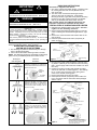
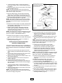
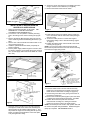
Recessed Mount
Ceiling Mounted
Fan Forced Heater
SERIES 500
Surface Mount
Installation & Maintenance Instructions
Dear Owner,
Congratulations! Thank you for purchasing this new heater manufactured by a division of Marley
Engineered Products. You have made a wise investment selecting the highest quality product in the heating industry. Please carefully read the installation and maintenance directions shown in this manual.
You should enjoy years of efficient heating comfort with this product from Marley Engineered Products...
the industry’s leader in design, manufacturing, quality and service.
... The Employees of
Marley Engineered Products
!
WARNING
Read Carefully - These instructions are written to help you
prevent difficulties that might arise during installation of
heaters. Studying the instructions first may save you considerable time and money later. Observe the following procedures and cut your installation time to a minimum.
6.
7.
1. To prevent electrical shock, disconnect all power coming
to heater at main service panel before wiring or servicing.
2. All wiring must be in accordance with the National and
Local Electrical Codes and the heater must be grounded
as a precaution against possible electric shock.
3. Verify the power supply voltage coming to heater matches the ratings printed on the heater nameplate before
energizing.
4. Do not install the heater closer than 12” (305mm) to any
wall for models 548, 542, 547 and 24” (610mm) to any
wall for models 558, 552 and 557.
5. Do not insert or allow foreign objects to enter any ventila-
8.
9.
10.
tion or exhaust opening as this may cause an electric
shock, fire, or damage to the heater.
To prevent a possible fire, do not block air intakes or
exhaust in any manner. Keep combustible materials, such
as crates, drapes, etc., away from heater.
A heater has hot and arcing (sparking) parts inside. Do
not use it in areas where gasoline, paint, or flammable
liquids are stored.
This heater is not approved for use in corrosive atmospheres such as marine, green house, or chemical storage
areas.
The heater enclosure must be securely mounted to ceiling or framing capable of supporting the heater (45 lbs /
20.4 kg). Failure to do so could allow heater to fall.
Do not operate heater without outlet grilles installed.
When installing grilles with louver guides, make sure
guides drop into position so they cannot slide out during
use.
SAVE THESE INSTRUCTIONS
1
IMPORTANT
UNPACKING INSTRUCTIONS
!
WARNING
!
FAILURE TO INSTALL THE FOUR MOUNTING NUTS
COULD RESULT IN THE HEATER FALLING. (SEE FIG. 2)
WARNING
!
FAILURE TO INSTALL THE FOUR SCREWS, COULD ALLOW
THE SURFACE WRAPPER TO FALL. (SEE FIG. 2)
This heater is shipped in two cartons.
1. One carton contains the Heater Section, consisting of the
fan, heating elements and controls (Models 542, 547,
548, 557 & 558).
2. The other carton contains the Mounting Enclosure.
There are two types of enclosures: a) Recessed
Mounting Enclosure, Type REA and b) Surface Mounting
Enclosure, Type SEA. Either enclosure is acceptable
with any of the Model 500 Series heater sections.
Both a Heater Section and a Mounting Enclosure are
required to complete the installation of this heater.
INSTALLATION OF SURFACE MOUNTED HEATER
Field Conversion for Lower Wattage Rating
(Figure 12)
To convert the heater to a lower wattage rating, completely remove
one(1) red jumper wire from one heating element for 25% wattage
reduction. Completely remove two (2) red jumper wires for a 50%
wattage reduction. Discard the jumper(s). Be sure the remaining
wires are securely connected.
Conversion for 3Ø Installation
Heater is factory wired for connection to 1Ø only. To convert to 3Ø,
remove and discard blue jumper wire between L1 & L3. (See Fig. 12,
page 5).
1. Determine the desired location of the heater. See warning No. 4 for min. mounting clearances.
2. Remove the Surface Mounting Plate (Figure 1) from the
carton containing the Surface Mounting Enclosure, Type
SEA.
3. Remove one of the knockouts and install a cable or conduit connector.
4. Install the optional disconnect switch (if required) as
shown in Figure 1.
7/8”(22,2mm) &
1-1/8”(28.6mm)
Nested Knockout
NOTE: Field wiring must be #10 AWG. min. rated 90°C,min.
Wiring Compartment Volume: 252in3 (4130cm3)
1/2”(12.7mm)
Surface
Knockout
Mounting Plate
ADJUSTABLE DISCHARGE GRILLES
CUSTOM AIR FLOW PATTERNS
1. The discharge air pattern is determined by the arrangement of the discharge grilles.
2. Care must be taken when selecting location of heater.
NOTE: The discharge grill area is rectangular; the discharge
grilles can only be installed parallel to the intake louvers.
Discharge Air
Grille Arrangement
Screw (2)
7/8”(22,2mm) 1/2”(12.7mm)
Knockout
Knockout
Cable or conduit
connector
Surface Mounting
Plate
Figure 1
Custom Air
Flow Pattern
NARROW AIR PATTERN for high ceiling
applications (11’(3352mm) to 14’(4267mm)),
concentrates the heated air to ensure full penetration to the floor level.
Heater
Discharge
Grilles
8’
(2438mm)
Optional
Disconnect Switch
Air Pattern
on Floor
5. Run the power supply cable through the connector, leaving about 8” (203mm) of wire inside the surface mounting
plate. (Power supply cable must be # 10 AWG min. rated
90°C min.)
6. Position the surface mounting plate against the ceiling
and secure with bolts or screws (Figure 2). See Warning
No. 9. Connect the ground wire to the green ground
screw on the surface mounting plate.
7. Remove the heater section from its carton.
8. Install optional controls (if required) into the heater section in accordance with the Instruction Sheet packaged
with the control.
WIDE AIR PATTERN for standard ceiling
applications (8’(2438mm) to 10’(3048mm)),
disperses the air to give a gentle, less pronounced pattern while circulating all the air
from floor to ceiling.
Grounding
Screw
Surface Mounting
Plate
Stud (4)
Power Supply
Cable
Air Pattern on Floor
8’(2438mm)
Screws or
Bolts
(Not Supplied)
12”(305mm) Min.4kw
24”(609mm) Min. 5kw
12”(305mm) Min.4kw
24”(609mm) Min. 5kw
Thumb Pin
Hole (2)
24’(7315mm)
Heater Section
Nut (4)
ASYMMETRICAL AIR PATTERN directs
heated air in a specific direction, allowing
the heater to be located where space allows
with the heated air delivered to where it is
required.
Surface Wrapper
10’(3048mm)
Air Pattern on Floor
Thumb Pin
Hole (2)
Screw (4)
17’(5181mm)
Figure 2
2
Insure that “Thumb Pin” is pulled out
before positioning the surface wrapper on
the heater section. Depress “Thumb Pin”
after surface wrapper is sealed firmly
against the heater section.
9. To wire the heater, and/or to convert from single to
three-phase voltage, refer to “Electrical Wiring” (Figure
12, page 5).
10. Position the heater section over the studs on the surface
mounting plate (Figure 2).
NOTE: The end of the heater section with the terminal
block must be positioned at the end of the surface mounting
plate where the supply wiring enters.
Insure that “Thumb Pin” is pulled out
before positioning the face plate on
the heater section. Depress “Thumb
Pin” after face plate is sealed firmly
against the heater section.
Screw (4)
Recess Face
Plate
Thumb
Pin (2)
Heater Section
Nut (4)
11. Push the heater section onto the studs and securely
tighten four nuts (supplied) on the studs to secure the
heater section to the surface mounting plate (Figure 2).
12. Remove the Surface Wrapper from the carton containing
the Surface Mounting Enclosure, Type SEA.
NOTE: Insure that the “thumb pin” in each end of the discharge grille opening is pulled outward to allow the body of
the thumb pins to fit into the holes in the heater section.
(Figure 2).
Recess
Mounting Box
Thumb Pin
Hole (2)
Grounding Screw
Stud(4)
7/8” & 1-1/8” (22.2mm & 28.5mm) Knockout
1/2” (12.7mm) Knockout
Screw (3)
Screw (2)
1/2”(12.7mm) Knockout
13. Position the surface wrapper over heater section/surface
mounting plate, making sure that the thumb pins are in
the holes in the heater section.
14. With the surface wrapper seated firmly against the
heater section, depress the “thumb pins”. This will
cause the thumb pins to expand and will temporarily
hold the surface wrapper in place.
NOTE: The thumb pins are an aid to help position and hold
the surface wrapper during installation. Additional support
(step 15) is required. SEE WARNING PAGE 2.
7/8” & 1-1/8”
(22.2mm & 28.5mm)
Nested Knockout
Figure 3
Side
Panel
Cable or
conduit
connector
Optional
Disconnect
Switch
9. Push the heater section on to the studs and securely
tighten four nuts (supplied) on the studs to secure the
heater section to the recess mounting box (Figure 3).
See Warning page 2.
10. Remove the Recess Face Plate (Figure 3) from the carton containing the Recess Mounting Enclosure, Type
REA.
NOTE: Insure that the “thumb pin” in each end of the discharge grille opening is pulled outward to allow the body of
the thumb pins to fit into the holes in the heater section.
(Figure 3.) See warning page 2.
15. Install and securely tighten four screws (supplied) to
secure the surface wrapper to the heater section (Figure
2).
16. Install discharge air grilles. (Refer to “Installation of
Discharge Air Grilles”, page 5.)
INSTALLATION OF RECESS MOUNTED
HEATER IN T-BAR CEILING
11. Position the recess face plate over the heater
section/recess mounting box, making sure that the
thumb pins are in the holes in the heater section.
12. With the recess face plate seated firmly against the
heater section, depress the “thumb pins”. This will
cause the thumb pins to expand and will temporarily
hold the recess face plate in place.
NOTE: The thumb pins are an aid to help position and hold
the recess face plate during installation. Additional support
(Step 13) is required. SEE WARNING PAGE 2.
The recess mounted heater will mount in any standard 2’ x
2’ (609mm x 609mm) T-Bar (drop) ceiling. SEE WARNING
NO. 4 FOR MIN. MOUNTING CLEARANCES & WARNING
NO. 9.
1. Remove the recess mounting box (Figure 3) from the
carton containing the Recess Mounting Enclosure, Type
REA.
2. Remove three screws and the side of the recess mounting box to allow for easier wiring (Figure 3).
3. Remove one of the knockouts and install a cable or conduit connector (Figure 3).
4. Install the optional disconnect switch (if required as
shown in Figure 3).
5. Remove the heater section from its carton.
6. Install optional controls (if required) into the heater section in accordance with the Instruction Sheet packaged
with the control.
13. Install and securely tighten four screws (supplied) to
secure the recess face plate to the heater section
(Figure 3).
14. Determine the desired location of the heater.
15. Position the heater in the T-bar grid (Figure 4) and
secure as required. SEE WARNING NO. 9.
16. Run the power supply cable through the connector, leaving about 8” (203mm) of wire inside the recess mounting
box. (Power supply cable must be #10 AWG min. rated
90°Cmin.)
17. Connect the ground wire to the green ground screw on
the recess mounting box.
18. After wiring is complete, replace and secure the side of
the recess mounting box previously removed in Step 2.
19. Install discharge air grilles. (Refer to “Installation of
Discharge Air Grilles”, page 5.)
7. To wire the heater, and/or to convert from single to
three-phase voltage, refer to “Electrical Wiring” (Figure
12, page 5).
8. Position the heater section over the studs in the recess
mounting box (Figure 3).
NOTE: The end of the heater section with the terminal
block must be positioned at the end of the recess mounting
box where the supply wiring enters.
3
8. Secure the recess mounting box to the building structure
using a minimum of four fasteners (not supplied).
9. Remove the heater section from its carton.
TBar
Grid
Heater
Power Supply
Cable
12”(305mm) Min.4kw
24”(609mm) Min. 5kw
12”(305mm) Min.4kw
24”(609mm) Min. 5kw
Figure 4
3/8” (9.5mm)
Wall
Wall
INSTALLATION OF RECESS MOUNTED
HEATER IN PLASTER CEILING
Recess Mounting
Box
1. Determine the desired location of the heater. SEE
WARNING NO. 4 FOR MIN. MOUNTING
CLEARANCES AND WARNING NO. 9.
2. Cut a 22-1/4” x 22-1/4” (565mm x 565mm) mounting
hole in the ceiling for the recess mounting box (Figure
5).
3. Remove the Recess Mounting Box (Figure 6) from the
carton containing the Recess Mounting Enclosure, Type
REA.
4. Remove one of the knockouts and install a cable or conduit connector (Figure 6).
5. Install the optional disconnect switch (if required) as
shown in Figure 6.
6. Run the power supply cable through the connector, leaving about 8” (203mm) of wire inside the recess mounting
box. (Power supply cable must be #10 AWG min. rated
90°C min.)
Wall
Wall
Figure 7
10. Install optional controls (if required) into the heater section in accordance with the Instruction Sheet packaged
with the control.
11. To wire the heater, and/or to convert from single to
three-phase voltage, refer to “Electrical Wiring” (Figure
12, page 5).
12. Position the heater section over the studs in the recess
mounting box (Figure 8).
NOTE: The end of the heater section with the terminal
block must be positioned at the end of the recess mounting
box where the supply wiring enters.
Power
Supply
Cable
Grounding
Screw
22-1/4”
(565mm)
Stud (4)
22-1/4”
(565mm)
Nut (4)
Heater
Section
12”(305mm) Min.4kw
24”(609mm) Min. 5kw
Wall
12”(305mm) Min.4kw
24”(609mm) Min. 5kw
Wall
Figure 5
Thumb Pin Hole
Recess Face
Plate
8”(2438mm) to Floor Min.
14”(4267mm) to Floor Max..
1/2” (12.2mm)
Knockout
Screw (4)
7/8” & 1-1/8”
(22.2 & 28.5mm)
Nested Knockout
Recess
Mounting
Optical
Screw (2)
Disconnect Box
Switch
7/8” & 1-1/8”
(22.2 & 28.5mm)
Nested Knockout
Figure 8
13. Push the heater section onto the studs and securely
tighten four nuts (supplied) on the studs to secure the
heater section to the recess mounting box (Figure 8).
14. Connect the ground wire to the green ground screw on
the recess mounting box.
15. Remove the recess face plate (Figure 8) from the carton
containing the Recess Mounting Enclosure, Type REA.
16. Position the recess face plate over the heater
section/recess mounting box, making sure that the
thumb pins are in the holes in the heater section.
NOTE: The thumb pins are an aid to help position and hold
the recess face plate during installation. Additional support
(Step 18) is required. SEE WARNING PAGE 2.
1/2” (12.2mm)
Knockout
Cable or
Conduit
Connector
Recess
Mounting Box
Figure 6
7. Place the recess mounting box in the ceiling opening
and align the marks on the sides of the mounting box
with the bottom of the finished ceiling (Figure 7). This
will position the edge of the mounting box 3/8” (9,5mm)
below the ceiling and will allow the recess face plate
to lay flat against the ceiling.
Insure that “Thumb Pin” is pulled
out before positioning the face
plate on the heater section.
Depress “Thumb Pin” after face
plate is sealed firmly against the
heater section.
4
17. With the recess face plate seated firmly against the
heater section, depress the “thumb pins”. This will
cause the thumb pins to expand and will temporarily
hold the recess face plate in place.
18. Install and securely tighten four screws (supplied) to
secure the recess face plate to the heater section
(Figure 8).
19. Install discharge air grilles. (Refer to “Installation of
Discharge Air Grilles”, page 5.)
!
WARNING
TO PREVENT THE DISCHARGE GRILLES GUIDES
FROM FALLING, THE GUIDES MUST BE FIT (LOCKED)
IN POSITION AS SHOWN IN FIGURE 11.
1. Set the thermostat (internal or remote) to highest setting.
This will energize the heating elements and the fan
causing air to flow from the center of the heater.
2. After the operational check, set the thermostat to obtain
the desired comfort level.
INSTALLATION OF DISCHARGE GRILLES
NOTE: Heater contains a fan delay on shut down.
-- The fan energizes immediately when the thermostat
turns on the elements.
-- Fan will operate for a short time after the heating elements are turned off (approx. 1min.)
* TO WIRE 3Ø: (REFER TO STANDARD WIRING
1. Remove the two discharge grilles and two louver guides
from the enclosure carton.
2. Refer to “Adjustable Discharge Grilles Custom Air Flow
Patterns” section of this instruction sheet to determine
desired air flow direction.
3. Place the two discharge grilles onto a flat surface in the
desired configuration with tabs on each end of grilles
upward.
4. Fit the two louver guides over the two discharge grilles
as shown in Figure 9.
5. While holding the assembly together with both hands, fit
one side of assembly into the opening of the enclosure,
and slide this side inward while fitting the opposite side
into the enclosure. (See Figure 10.) Slide the assembly
into position so that the bottom portion of each guide
locks into the opening.
ELECTRICAL WIRING
Standard
Wiring
Diagram
(Factory
Wired)
Discharge Grille (2)
Wiring
Conversion
For 3Ø
Installation
Louver Guides
* See Note
Below
Figure 9
Tabs on
Discharge Grilles
Must Face
Upward
Wiring
Conversion
To lower
Wattage
(1Ø)
OPERATION
1
Slide grille
assembly into
opening far
enough to clear
louver ends.
Figure 12
DIAGRAM)
2
Push grille assembly up
into opening.
COMPLETELY REMOVE BLUE JUMPER WIRE
BETWEEN L1 AND L3 ON THE POWER BLOCK.
3
Slide grille assembly
into position in opening.
MAINTENANCE
Figure 10
1. Once each year the heater should be cleaned to remove
dust and foreign material which has collected during the
heating season.
2. Turn off all electrical power at the circuit breaker of fuse
box to disconnect the electrical power to heater.
3. Remove dust and other foreign material with a vacuum
cleaner nozzle or dust cloth.
4. Turn on the main line switch to restore power to the
heater.
Louver Guide
1
Bottom of each louver
guide Must lock in
position in opening.
Figure 11
Louver
Guide
5
IMPORTANT INFORMATION
SPECIFICATIONS
Cat. No.
-548
-542
-547
-558
-552
-557
Heater
Section
Only
Heater
Section
Only
Amps3
CFM
°F (°C)4
Kw1
BTU/Hr. (600)
Volts
Phase2
4/3/2
13.7/10.2/6.8
208
240
277
1-3
1-3
1
19.2/14.4/9.6 283
16.7/12.5/8.3 (133,5
14.5/10.8/7.2 dm3/s)
51
(28,3)
5/3.8/2.5 17.2/13.0/8.5
208
240
277
1-3
1-3
1
20.8/15.8/10.4 283
20.8/15.8/10.4 (133,5
18.1/13.7/9.0 dm3/s)
45
(25)
-SEA
Surface mounting enclosure - to be used with above heater sections. Dim: 20” (508mm) L x
16-1/2” (419mm) W x 5-3/4” (146mm) D.
-REA
Recess mounting enclosure - to be used with above heater sections. Dim: 23-3/4” (603mm) L x
23-3/4” (603mm) W x 7” (177mm) D.
Field Installed Kits
Acc.
-T
Thermostat SPST - Range 40 to 95°F (4 to 35°C).5
-24
Relay (Time Delay 45 - 60 sec. to close when energized) requires 24 volt supply from remote source.
-R12
Relay (Time Delay 45 - 60 sec. to close when energized) requires 120 volt supply from remote source.
-DS
Power Disconnect Switch (3-Pole) 30 amps, 600 volts, 1Ø, 60 Hz.
-TK
Trim Ring for mounting on permanent ceiling (can not be factory installed).
-TR4
CEILING HEATER FAN DECK
208/240 V Primary Transformer/24 V sec. and 24 V holding coil control relay.
-TR7
277 V Primary Transformer/ 24 V sec. and 24 V holding coil control relay.
BÀTI DU VENTILATEUR, APPAREIL DE PLAFOND
VOLTS
WATTS
AMPS
277VAC
5000
18.1
FOR SUPPLY CONNECTIONS USE NO. 10AWG
OR LARGER WIRES SUIT ABLE FOR 90°CMIN.
NAMEPLATE
MODEL NO.
Factory wired for highest wattage, field convertible to lower wattages.
Factory wired 1Ø, field convertible to 3Ø.
On dual phase units, maximum amp draw is listed.
4
Temperature difference at highest rated wattage.
1
557
DATE CODE:
1195
774G LISTED
AIR HEATER
UTILISER UN CÁBLE D´ALIMENTATION D´AU MOINS
NO. 10AWG CONVENANT À UNE TEMPERATURE
D´AU MOINS 90°C.
2
3
MARLEY ENGINEERED PRODUCTS
BENNETTSVILLE, SC 29512
4104-2062-005
LIMITED WARRANTY
All products manufactured by Marley Engineered Products are warranted against defects in workmanship and materials for one year from date of installation,
except heating elements which are warranted against defects in workmanship and materials for five years from date of installation. This warranty does not
apply to damage from accident, misuse, or alteration; nor where the connected voltage is more than 5% above the nameplate voltage; nor to equipment
improperly installed or wired or maintained in violation of the product’s installation instructions. All claims for warranty work must be accompanied by proof of
the date of installation.
The customer shall be responsible for all costs incurred in the removal or reinstallation of products, including labor costs, and shipping costs incurred to return
products to Marley Engineered Products Service Center. Within the limitations of this warranty, inoperative units should be returned to the nearest Marley
authorized service center or the Marley Engineered Products Center, and we will repair or replace, at our option, at no charge to you with return freight paid
by Marley. It is agreed that such repair or replacement is the exclusive remedy available from Marley Engineered Products.
THE ABOVE WARRANTIES ARE IN LIEU OF ALL OTHER WARRANTIES EXPRESSED OR IMPLIED. AND ALL IMPLIED WARRANTIES OF MERCHANTABILITY AND FITNESS FOR A PARTICULAR PURPOSE WHICH EXCEED THE AFORESAID EXPRESSED WARRANTIES ARE HEREBY DISCLAIMED AND EXCLUDED FROM THIS AGREEMENT. MARLEY ENGINEERED PRODUCTS SHALL NOT BE LIABLE FOR CONSEQUENTIAL DAMAGES
ARISING WITH RESPECT TO THE PRODUCT, WHETHER BASED UPON NEGLIGENCE, TORT, STRICT LIABILITY, OR CONTRACT.
Some states not do allow the exclusion or limitation of incidental or consequential damages, so the above exclusion or limitation may not apply to you. This
warranty gives you specific legal rights, and you may also have other rights which vary from state to state.
For the address of your nearest authorized service center, contact Marley Engineered Products in Bennettsville, SC, at 1-800-642-4328. Merchandise
returned to the factory must be accompanied by a return authorization and service identification tag, both available from Marley Engineered Products. When
requesting return authorization, include all catalog numbers shown on the products.
HOW TO ORDER REPAIR PARTS
In order to obtain any needed repair or replacement
parts, warranty service or technical information, please
contact Marley Engineered Products Service Center tollfree by calling 1-800-642-HEAT.
When ordering repair parts, always give the information listed as follows:
1. The Part Number
2. The Model Number
3. The Part Description
4. Date of Manufacture
ECR 35011
Part No. 5200-2069-009
04/02
6
SPX Corporation
470 Beauty Spot Rd. East
Bennettsville, SC 29512 USA