1
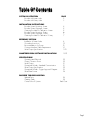
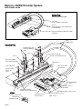
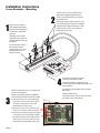
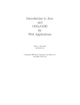
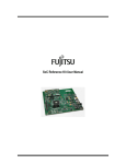
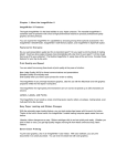
Preliminary
Mercury 3000Si Dual Axis Averager
™
Motion Control Feedback Using Averaging of Two Sensors
Installation Manual
and Reference Guide
Manual No. IM-M3000SiDAA Rev S5
Introduction
MicroE Systems was founded to advance encoder technology to
a level never before achieved. Our objective was to design encoder
systems that would be small enough to fit into densely packed OEM
equipment designs, affordable enough for cost-sensitive applications
and easy enough to enable installation, setup and alignment by
assemblers with little training. We are pleased to say that all of
these goals have been realized with the introduction of the Mercury
family of encoders.
Sensor shown
actual size
M10
Precautions
1
Follow standard ESD precautions. Turn power off before connecting the sensor.
Do not touch the electrical pins without static protection such as a grounded
wrist strap.
2
Do not touch the glass scale unless you are wearing talc-free gloves or finger
cots. Please read this installation manual for full instructions.
LASER SAFETY INFORMATION: Mercury & ChipEncoder
This product is sold solely for use as a component (or replacement) in an electronic product; therefore it is not
required to, and does not comply with, 21 CFR 1040.10 and 1040.11 which pertain to complete laser
products. The manufacturer of the complete system-level electronic product is responsible for complying with 21
CFR 1040.10 and 1040.11 and for providing the user with all necessary safety warnings and information.
MicroE encoders contain an infrared laser diode or diodes. Emitted invisible laser radiation levels have been
measured to be within the CDRH Class 1 range, which is not considered hazardous; however, to minimize
exposure to the diverging beam, the encoder sensor should be installed in its operational configuration in close
proximity to the encoder scale before power is applied.
INVISIBLE LASER RADIATION
DO NOT VIEW DIRECTLY WITH OPTICAL
INSTRUMENTS
(MICROSCOPES, EYE LOUPES OR
MAGNIFIERS)
• Invisible laser radiation; wavelength: 850 nm
• Max power 2.4 mW CW (4.8 mW CW for Mercury II™)
• CAUTION – The use of optical instruments with this product will increase eye hazard. DO NOT VIEW
DIRECTLY WITH OPTICAL INSTRUMENTS (MICROSCOPES, EYE LOUPES OR MAGNIFIERS).
• All maintenance procedures such as cleaning must be performed with the MicroE encoder turned off.
• Do not insert any reflective surface into the beam path when the encoder is powered.
• Do not attempt to service the MicroE encoder.
Patents
Covered by the following patents: US 5,991,249; EP 895,239; JP 3,025,237; US
6,897,435; and EP 1,451,933. Additional patents and patents pending may apply.
Table Of Contents
SYSTEM ILLUSTRATION
Encoder with Linear scale
Encoder with Rotary scale
INSTALLATION INSTRUCTIONS
Encoder System Mounting - Linear
Encoder System Alignment - Linear
Centering the Index & Calibration - Linear
Encoder System Mounting - Rotary
Encoder System Alignment - Rotary
Centering the Index & Calibration - Rotary
PAGE
2
3
4
5
5
6
7
7
REFERENCE SECTION
Installation of Linear Scales
Grounding Instructions
Recommendations for Power
Customer Interface Cable Requirements
Serial Output Specifications
8
9
9
10
11-12
SMARTPRECISION SOFTWARE INSTALLATION
13-19
SPECIFICATIONS
Operating and Electrical
Output Connector Pinout
Serial Output
Operational Modes: Standard Communication
Serial Output Specificattion
Operational Modes - Trigger Approach Diagram
Serial Data Format
20
20
21
21
22
23
24
ENCODER TROUBLESHOOTING
Selected Topics
Cleaning Scales
Contact MicroE Systems
24
25
Back Cover
Page 1
Mercury 3000Si Encoder System
with Linear scale
System View
Shown with linear scale
Glass scale
(shown mounted on a linear slide)
Sensors
(shown attached on a linear slide base with
mounting brackets)
Dual Axis/SmartPrecision electronics module
(interpolator)
Double
shielded cables
Expanded View
Mounting screws & flat
washers (2 needed per
screw)
Sensor 2
Sensor mounting holes (2)
Optional sensor benching pins (3)
Sensor 1
Typical user-supplied
sensor mounting brackets
End locator pin
Cover: Sensor cables
and connectors
Center index mark
Bracket mounting
holes (2) per
sensor
Power/Calibration Sensor 2
Signal - Sensor 2
USB interface
Scale reference datum;
example shown with benching pins
Detail A
Top reflective linear scale
End index mark
Scale benching edge
Page 2
25 pin High Density
D-sub connector
Index Calibration Button - Sensor 1 and 2
Power/Calibration - Sensor 1
Signal - Sensor 1
Mercury 3000Si Encoder System
with Rotary scale
System View
Shown with Rotary scale
Sensors
(shown attached to a customer-supplied
mounting brackets)
Rotary scale
Dual Axis/SmartPrecision electronics module
(interpolator)
Expanded View
Mounting screws & flat
washers (2 needed per screw)
Sensor 1
Sensor 2
Double
shielded cable
Mounting hole (2)
Typical user-supplied
sensor mounting bracket
Top reflective
rotary scale
Rotary scale
PowerPower/Calibration Sensor 2
Signal - Sensor 2
Power/Calibration - Sensor 1
Signal - Sensor 1
USB interface
Index Calibration Button - Sensor 1 and 2
25 pin High Density
D-sub connector
Page 3
Installation Instructions
Linear Encoders - Mounting
2
1
Attach the scale to the base
slide. Reference the preferred
datum on the interface drawing
for either end or center index
orientation.
Install the sensors on your mounting surfaces
referencing the appropriate datum surface as
shown on the interface drawing. Use 2 washers
per mounting screw.
Benching pins may be used to locate each sensor
if the system mechanical tolerances are adequate.
See data sheet for alignment tolerances, or keep
mounting screws loose for sensor alignment if
benching pins are not used.
Depending on the mounting
method, attach the scale to the
slide with adhesive. Refer to pg.
8 for details.
Be sure the grating surface of
the scale faces the sensor.
Insure that there is no contact
between these surfaces or
damage may result.
4
Tighten the thumb screws.
Route the sensor cables through your equipment
to the Dual Axis SmartPrecision electronics module.
3
Power up the system. The Power and Signal indicators for both sensors will illuminate.
Sensor 1
B) Attach each sensor's 5 X 2 connector to the
mating 5 X 2 connector on the circuit board.
C) Route the sensor cables through their channels
in the center of the connector body and place
the cable's hex sleeves in the matching recesses.
Attach the top half of the connector housing
to the bottom half using the three cover screws.
Sensor 2
Page 4
Connect the SmartPrecision electronics to the
controller using the pinout diagram described on the
interface drawing.
Insure proper system grounding. Refer to the procedure on pg 9.
CAUTION: observe precautions for handling electrostatic sensitive devices.
A) Remove the three cover screws and the top
half of the connector housing. Do not pull on
the 25-pin D-sub connector or the circuit
board under the insulation layer.
Be sure the source power is off before
connecting the SmartPrecision plug.
Installation Instructions
Linear Encoders - Alignment
If benching dimensions cannot be provided, proper sensor alignment may require minor
adjustments to each sensor’s position with respect to the scale. This can be performed easily
using the LED alignment indicators, as illustrated below.
IMPORTANT: Confirm that the Proper Alignment LED blinks when passing over the index.
If not, readjust the sensor in the Y direction and repeat the above procedure. When alignment is
completed, tighten the sensor mounting screws (0.37Nm [3.3 inch-lbs.] maximum torque).
6
x
Y
5
For sensor 1, the Sig 1 multicolor LED will turn from red to yellow-orange to green depending
on sensor alignment. Slowly move the sensor by allowing it to slide on the mounting surface
until the Sig 1 multicolor LED turns green. Optimal alignment will be displayed as a “Bright
Green” LED. Repeat the last step, using sensor 2 and the Sig 2 multicolor LED, to align
sensor 2.
θz
Z
To align the sensor, move it
in the Y or θz directions.
Improper
Alignment LED
Red:
Sensor 1
Improved
Alignment LED
Yellow-Orange:
Sensor 1
Proper
Alignment LED
Green:
Sensor 1
Power/
Calibration
Sensor 1
Power/
Calibration
Sensor 1
Power/
Calibration
Sensor 1
Improper
Alignment LED
Red:
Sensor 2
Improved
Alignment LED
Yellow-Orange:
Sensor 2
Proper
Alignment LED
Green:
Sensor 2
Power/
Calibration
Sensor 2
Power/
Calibration
Sensor 2
Power/
Calibration
Sensor 2
Confirm proper alignment over
the full range of motion.
The “Proper Alignment” LED
must remain green over the
entire range for both sensors.
If not aligned over the entire
range of motion, loosen the
sensors mounting screws and
repeat step 5.
7
IMPO RTANT
OUTPUT C ALIBRATION PROCEDURE
This procedure must be completed for proper system
operation each time the sensors are aligned or if the
SmartPrecision electronics module is replaced
Position each sensor at least 7mm (1/4”) away from the index
mark on the scale. Next, for sensor 1, push the
Index/Calibration button inside the module just once. The
Power/Calibration indicator for sensor 1, will flash continuously.
Move the scale past sensor 1 in both directions so that the
index mark passes under sensor 1. When the calibration procedure is complete, the Power/Calibration indicator for sensor 1
stops flashing.
To calibrate sensor 2, push the Index/Calibration button twice. The
Power/Calibration indicator for sensor 2 will flash continuously.
Move the scale past sensor 2 in both directions so that the
index mark passes under sensor 2. When the calibration procedure is complete, the Power/Calibration indicator for sensor 2
stops flashing.
Sensor 1: Proper
Alignment indicator
Sensor 1:
Calibration / Index
Set Up button
Push once.
Sensor 1: Power/
Calibration indicator
Sensor 2:
Calibration / Index
Set Up button
Push twice.
Sensor 2: Proper
Alignment indicator
Sensor 2: Power/
Calibration indicator
Page 5
Installation Instructions
Rotary Encoders - Mounting
2
1
Install the sensors on your mounting surface referencing the
appropriate datum surface as shown on the interface drawing.
Use 2 washers per mounting screw.
Benching pins may be used to locate each sensor if the system
mechanical tolerances are adequate. See data sheet for alignment
tolerances, or keep mounting screws loose for sensor alignment if
benching pins are not used.
Attach your hub/scale
assembly to the rotary
device. Refer to the
interface drawing. The
reflective surface of the
scale must face the
sensors.
4
3
Connect the SmartPrecision electronics to the controller
using the pinout diagram described on the interface
drawing.
CAUTION: observe precautions for handling electrostatic sensitive devices.
Insure proper system grounding. Refer to the procedure
on pg 9.
Route the sensor cables through your equipment
to the Dual Axis SmartPrecision electronics module.
Power up the system. The Power and Signal indicators for
both sensors will illuminate.
A) Remove the three cover screws and the top
half of the connector housing. Do not pull on
the 25-pin D-sub connector or the circuit
board under the insulation layer.
Sensor 1
B) Attach each sensor's 5 X 2 connector to the
mating 5 X 2 connector on the circuit board.
C) Route the sensor cables through their channels
in the center of the connector body and place
the cable's hex sleeves in the matching recesses.
Attach the top half of the connector housing
to the bottom half using the three cover screws.
Sensor 2
Page 6
Be sure the source power is off before
connecting the SmartPrecision plug.
Installation Instructions
Rotary Encoders - Alignment
If benching dimensions cannot be provided, proper sensor alignment may require minor
adjustments to each sensor’s position with respect to the scale. This can be performed easily
using the LED alignment indicators, as illustrated below.
IMPORTANT: Confirm that the Proper Alignment LED blinks when passing over the index.
If not, readjust the sensor in the Y direction and repeat the above procedure. When alignment is
completed, tighten the sensor mounting screws (0.37Nm [3.3 inch-lbs.] maximum torque).
6
Z
To align the sensor, move it
in the Y or θz directions.
Improper
Alignment LED
Red:
Sensor 1
Improved
Alignment LED
Yellow-Orange:
Sensor 1
Proper
Alignment LED
Green:
Sensor 1
Power/
Calibration
Sensor 1
Power/
Calibration
Sensor 1
Power/
Calibration
Sensor 1
Improper
Alignment LED
Red:
Sensor 2
Improved
Alignment LED
Yellow-Orange:
Sensor 2
Proper
Alignment LED
Green:
Sensor 2
Power/
Calibration
Sensor 2
Power/
Calibration
Sensor 2
Power/
Calibration
Sensor 2
Confirm proper alignment over the full range of motion.
The “Proper Alignment” LED must remain green over the entire
range for both sensors. If not aligned over the entire range of
motion, loosen the sensors mounting screws and repeat step 5.
Move the scale past both
sensor s so that the index
mark passes under both
sensors as described in
step 7.
x
Y
5
For sensor 1, the Sig 1 multicolor LED will turn from red to yellow-orange to green depending
on sensor alignment. Slowly move the sensor by allowing it to slide on the mounting surface
until the Sig 1 multicolor LED turns green. Optimal alignment will be displayed as a “Bright
Green” LED. Repeat the last step, using sensor 2 and the Sig 2 multicolor LED, to align
sensor 2.
θz
7
IMPO RTANT
OUTPUT C ALIBRATION PROCEDURE
This procedure must be completed for proper system
operation each time the sensors are aligned or if the
SmartPrecision electronics module is replaced
Position each sensor at least 7mm (1/4”) away from the index
mark on the scale. Next, for sensor 1, push the
Index/Calibration button inside the module just once. The
Power/Calibration indicator for sensor 1, will flash continuously.
Move the scale past sensor 1 in both directions so that the
index mark passes under sensor 1. When the calibration procedure is complete, the Power/Calibration indicator for sensor 1
stops flashing.
To calibrate sensor 2, push the Index/Calibration button twice. The
Power/Calibration indicator for sensor 2 will flash continuously.
Move the scale past sensor 2 in both directions so that the
index mark passes under sensor 2. When the calibration procedure is complete, the Power/Calibration indicator for sensor 2
stops flashing.
Sensor 1: Proper
Alignment indicator
Sensor 1:
Calibration / Index
Set Up button
Push once.
Sensor 1: Power/
Calibration indicator
Sensor 2:
Calibration / Index
Set Up button
Push twice.
Sensor 2: Proper
Alignment indicator
Sensor 2: Power/
Calibration indicator
Page 7
Reference Section
Installation of Linear Scales
Positioning the Scale
Note: Before beginning mounting procedure, use talc-free gloves or finger cots to handle the scales.
"Benching" the scale to the system means aligning the scale by means of benching pins. Pin locations are described on the appropriate interface drawing.
Two benching pins are recommended on the long side of the scale and one at the end as shown . This is marked datum A on the interface drawing.
the benching pins in from either end. 20% of the overall
1 Position
scale length is the recommended location from the edge.
sure the benching pins do not extend too high in the Z direction to
2 Beprevent
mechanical interference with the sensor or sensor mount.
0.2L
0.6L
L
0.2L
End
Benching
Pin
MicroE Systems
Benching pins
Mounting the Scale
MicroE Systems' linear scales should be affixed to the mounting surface. Two different approaches are described below:
Epoxy and RTV Mounting (Recommended for best accuracy)
sure the mounting surface is
1 Make
clean and dry.
End Benching
Pin
Mounting clamp
Hard epoxy
at one corner,
this end only.
scale clamps may be used to secure the
3 Optionally,
scale while the adhesive cures. Avoid damage to
Scale clamp
with adhesive
the top surface.
L
Mounting clamp
MicroE Systems
Mounting clamp
Side view showing
optional scale clamps
and scale. Space
clamps every 75mm
on scales over 150
mm in length.
RTV around entire
outside edge of scale.
Benching pins
2 Align the scale by placing the edges against the benching pins.
a hard epoxy, such as Tra-Con’s Tra-Bond 2116, to the end of the scale at the end benching pin. Apply 100% Silicone RTV adhesive
4 Apply
around the edges of the scale. This method allows thermal expansion from the benched end of the scale. After adhesive curing, remove
the scale mounting clamps or, if permanently installing clamps, make sure they do not interfere with the sensor or sensor mount.
Two Sided Adhesive Tape Mounting
Gently place the scale on the mounting surface. Positioning adjustments
Make sure the mounting surface is clean and dry. Peel the
be made until the scale is firmly pressed down. After final positioning,
1 cover paper off and place the scale above the final location. 3 can
push down on the top of the scale to secure it.
End Benching
Pin
Hard epoxy at
one corner,
this end only.
L
MicroE Systems
Benching pins
2 Align the scale by placing the edges against the benching pins.
Page 8
Reference Section
Grounding Instructions for Mercury 3000Si Dual Axis Encoder Systems
For Mercury 3000Si Dual Axis Averager encoder systems to operate reliably, it is essential that the sensor and cable shield are grounded properly according to the following instructions. The diagrams below show how to make the connections when the encoder's connector is plugged into the customer's controller chassis. If a customer-supplied extension cable is used, it should be a double shielded
cable with conductive connector shells and must provide complete shielding over the conductors contained within it over its entire
length. Furthermore, the shields should be grounded at the connection to the controller chassis the same way as the encoder connectors in the diagrams below.
Note: For best performance, isolate encoder shield from motor cable shields and separate encoder cable as far possible from motor cables.
Sensors mounted with good electrical contact to a well-grounded surfaces (preferred)
1. 25-pin D-sub connector grounding: The encoder's connector shell must be in intimate, electrically conductive contact with the customersupplied mating connector, which must be isolated from the controller's ground. If a customer-supplied shielded cable connects the encoder
to the controller, then the shielding on the customer-supplied cable must be isolated from the controller's ground.
2. The sensors’ mounting surfaces must have a low impedance (DC/AC) connection to ground. The encoder sensors’ mounting surfaces may have
to be masked during painting or anodizing to insure good electrical contact with the sensors.
Electrically conductive
mechanical connection
(as supplied by MicroE
Systems).
Inner Shield: Insulated from outer shield,
sensor and connector housing. Connected
to circuit common internally.
Outer Shield: Connect to sensor
and connector housing.
Do not ground shroud.
Sensors mounted to a surfaces that are grounded through bearings or poorly-grounded surfaces, or non-conducting surfaces
1. 25-pin D-sub connector grounding: The encoder's connector shell must be in intimate, electrically conductive contact with the customer-supplied mating
connector, which must be connected to the controller's ground. If a customer-supplied shielded cable connects the encoder to the controller, then the
shielding on the customer-supplied cable must be connected to the controller's ground. The controller must be grounded to earth at the point of installation.
2. The encoder sensors must be mounted so that they are electrically isolated from ground.
Recommendations for Power
Mercury encoders require a minimum of 4.75V DC continuously. When designing circuits and extension cables to use Mercury encoders, be sure to
account for voltage loss over distance and tolerances from the nominal supply voltage so that at least 4.75V DC is available to the Mercury encoder
under all operating conditions. The input voltage should not exceed 5.25V DC.
Page 9
Customer Interface Cable Requirements
Customer cables that interface to Mercury series encoders must have the following characteristics:
• Twisted pair signal wiring.
• Characteristic impedance of 100-120 ohms.
• Sufficient wire gauge to meet the minimum voltage requirement at the encoder, for example 24AWG gauge wire for a 2m length cable.
Examples of acceptable cables with 24 AWG gauge wire and 5 twisted pairs are Belden 9832, 8105 or other manufacturer’s
equivalents.
• Single shield cable with a minimum of 90% coverage. Note that a double shielded cable may be required in high-noise applications.
Signal Wiring:
Each differential signal should be connected to a corresponding twisted pair as follows:
Mercury 3000SiDAA
Signal
Twisted Pair
SD0+
SD0Trigger+
TriggerSCK+
SCKN_CS+
N_CS+5V
GND
Pair 1
Pair 2*
Revision pending.
Pair 3
Pair 4
Pair 5
* For synchronous system connection only.
Shield Termination:
The customer's cable shield should be in 360° contact with the connector shroud and the connector shell to provide complete shielding. The
connector shell should be metal with conductive surfaces. Suggested metal connector shells for use with Mercury 3500, 3000, 3000Si,
3000SiDAA, 3000DAA, and 2000 encoders: AMP 748676-1 or equivalent; for Mercury 1000 and 1500S encoders: AMP 745172-3, -2, or -1
where the dash number is dependent on the customer's outside cable diameter. The shield should be terminated as illustrated in the following
diagram.
Fold braided shield back over jacket. Example shows double-shielded cable. Dimensions shown
are for illustration only.
Page 10
Serial Output Specification
Introduction
Historically, the method of choice for many optical position feedback systems has been A quad B (Quadrature) output. The limitation
of this method is output speed, especially when the interpolation level is high. When the optical sensor speed and/or the
interpolation multiplier is set high, the Quadrature output frequencies will be extremely high and out of the range of the
Quadrature counters of most standard motion controllers.
This limitation can be avoided by sending the position information in parallel format or in a serial word format. The parallel
formats are cumbersome to cable (especially wide word lengths) and are more susceptible to noise interference. Therefore, a
serial data word format is the data communication method of choice.
The Mercury 3000Si Dual Axis Averager Interpolator has the ability to output a position word in a serialized format. This allows
very fast communication between an interpolator and customer application. The speed limitation of the Quadrature format is
thus eliminated.
Signal Description
The interface from your electronics to the Mercury 3000SiDAA interpolator uses four signals, n_spiEnable (n_CS), spiDataOut
(SDO), spiClock (SCK), and optional spiTrigger (TRIG). Each signal is differential and RS-422 compatible. See table for interpolator
signal names, pin names, and pin locations:
Signal Description
Signal name
Pin Name
Function
n_spiEnable
n_CS+
n_CSSCK+
SCKSDO+
SDOTRIG+
TRIG-
Chip Select+
Chip SelectSerial Clock+
Serial ClockSerial Data Out+
Serial Data OutExternal Trigger+
External Trigger-
spiClock
spiDataOut
spiTrigger
I/O
Interpolator
Referenced
Input
Input
Input
Input
Output
Output
Input
Input
15 pin HD
Connector
7
8
14
15
5
4
10
9
Revision pending.
Page 11
Serial Output Specification
Index Processing
A unique physical position is referenced on all gratings and is called an index position. The value of this position is determined
during an index capture routine initiated by a button press or the SmartPrecision Software and is permanently stored for use
after power cycling. The index value has the same resolution as the interpolated position.
The M3000SiDAA has four modes of operation that use the index position to generate a physical reference position. The position word calculated by the M3000SiDAA electronics is a 28-bit number, which includes 18 fringe counter bits and 10 subfringe interpolation bits. The fringe counter keeps track of the number of electrical cycles encountered caused by a grating
moving past a sensor and can be reset. The sub-fringe position is absolute because the voltage relationship between sine and
cosine are fixed electrically and therefore cannot be reset or cleared.
A physical mark on the grating called an index window is used to generate an accurate index position. The index window
is approximately one fringe wide. By monitoring the edges of the window with respect to the absolute sub-fringe position
during the index capture mode, an accurate index position is calculated and stored.
At power up the encoder is in an undefined position relative to the outside world. By traveling past the index mark on the scale
and knowing where the index is relative to the outside world the encoder position becomes defined. The M3000SiDAA supports the following index processing modes:
No Index: No changes are made to the position word at the index mark.
Mode 1:
Zeros the fringe counter at the first encounter with index mark after power up.
Mode 2:
Zeros the fringe counter at every encounter with index mark.
Mode 3:
Zeros the fringe counter at the first encounter with index mark after power up and
subtracts the index position from the calculated position making the index mark the
zero position of the encoder.
Mode 4:
Zeros the fringe counter at every encounter with index mark after power up and
subtracts the index position from the calculated position making the index mark the
zero position of the encoder.
The Index mode can be factory set or selected by the customer using the optional SmartPrecision software.
Page 12
Optional SmartPrecision Software Installation Instructions
Hardware Requirements:
SmartPrecision Software for M3000SiDAA requires a PC with the following minimum specifications:
· Windows 2000 or XP operating systems
· 300MHz
· 32Mb RAM
· 1024 x 768 or higher screen resolution with High Color (16 bit color)
· 20Mb free disk space
· One USB port (Version 1.1 or higher)
MicroE SS300cDI SmartPrecision Software (Preliminary)
Software Notes:
1)
2)
This is Preliminary Software - Functionality not comprehensively tested and some limitations exist.
Intended for use on Windows 2000 or XP systems, with display resolution of at least 1024x768 (1024x768 is
optimal).
Installing the Software:
1)
2)
3)
IMPORTANT - INSTALL SOFTWARE BEFORE CONNECTING ELECTRONICS - this will allow the proper driver files
to be copied to the PC.
Insert Install CD - if setup does not automatically start - navigate to CD folder and run 'setup.exe'
To start the software - Click on 'Start>Programs>MicroE SmartPrecision for SS300cDI>SS300cDI Software' in the
Start Menu.
Installing the USB Driver:
USB Driver Installation Windows 2000:
1) Connect the USB cable between the host computer and the M3000SiDAA.
2) When the electronics are on, Windows will notify you it has found new hardware prompting you with a "Found
New Hardware" wizard. Press the Next button.
3) Select "Search for a suitable driver for my device (recommended)" and press the Next button.
4) Select "Specify a location" under "Optional search locations:" and press the Next button.
5) Press the Browse button to locate the SiF32X_USB.inf driver Installation file. SiF32X_USB.inf is located in
"Install Directory\Driver" under the directory where the software was installed. The default install directory is
..Program Files\MicroE Systems\ss300cDI.
Once this file is selected press the OK button.
6) Verify that the correct path and filename are shown and press the Next button.
7) Press the Finish button.
USB Driver Installation Windows XP:
1) Connect the USB cable between the host computer and the M3000SiDAA.
2) When the electronics are on,, Windows will notify you it has found new hardware prompting you with a "Found
New Hardware" wizard.
3) Select "Install from a list or specific location(Advanced)" and press the Next button.
4) Select "Include this location in the search". Press the Browse button to locate the SiF32X_USB.inf driver
installation file. SiF32X_USB.inf is located in "Install Directory\Driver" under the directory where the software
was installed. The default install directory is ..Program Files\MicroE Systems\ss300cDI. Once this file is selected
press the OK button.
5) Verify that the correct path and filename are shown and press the Next button.
6) Press the Finish button.
Page 13
Configuration and Setup - SmartPrecision Software
The M3000SiDAA interpolator module can be configured quickly and easily using the SmartPrecision Software. The M3000SiDAA interpolator will accept input from two separate encoders. The M3000SiDAA has three output channels. These can be configured to output
the following: Channel 1, Channel 2, Average ((Ch1+Ch2)/2), and/or Difference (Ch1-Ch2). The main screen shows Encoder Position,
Signal Level, Alarm Status, Data Plots, and Setup.
Encoder Position:
The Encoder Position box displays the current position data for each of the three output channels.
Each output can be reset or zeroed independently. The units can be changed from encoder counts, to any number of linear or rotary units.
Main Screen
Setup
Calibrate: Starts the calibration routine for the selected channel.
Configure: Allows user to configure the Input and Output Channel settings,
Calibration settings, SPI settings, and Hardware/Communication
settings
Display Settings: Configures the SmartPrecision Software Display
Data Plots
Encoder Signal: Displays the encoder signal plot for each input channel
Signal Strength: Displays the encoder signal strength for each in out channel.
Encoder Position: Displays the encoder position for each in out channel.
Page 14
M3000SiDAA Configuration
5
1
6
9
7
10
8
11
2
3
4
Configurations screen
1
2
Channel for Average Index:
Selects the input channel index that will be used for the Averaged output.
Example shown:
Index for Channel 1 selected
Output Channels [1 - 2 - 3]:
The Mercury Dual Axis Averager uses two sensors as inputs and has three output channels. Each sensor's signal is processed for
accuracy enhancement and interpolated. The signals, or their average or difference, are routed to each of the three output channels.
The routing assignments can be changed using SmartPrecision Software in the Configuration Settings dialog box. There are four possible configurations for the output channel assignments as shown in the following table:
Output Configuration
"Channel 1 - Channel 2 - Average"
Assignment for Output
Channel 1
Sensor 1
Assignment for Output
Channel 2
Sensor 2
"Channel 2 - Channel 1 - Difference"
Sensor 2
Sensor 1
"Average - Difference - Channel 1"
Average of Sensor 1
and Sensor 2
Difference
(Sensor 1 minus Sensor 2)
Difference
(Sensor 1 minus Sensor 2)
Average of Sensor 1
and Sensor 2
"Difference - Average - Channel 2"
Assignment for Output
Channel 3
Average of Sensor 1
and Sensor 2
Difference
(Sensor 1 minus Sensor 2)
Sensor 1
Sensor 2
Page 15
M3000SiDAA Configuration
3
4
5
6
7
8
Channel 1 & 2 Calibration Settings
If two separate axes are used the recommended setting is "Calibrate signal and center index". For applications where two
sensors are used on the same axis or if the index mark is not in the range of motion for one of the encoders, the "Calibrate
signal only" will allow proper calibration of the signal.
Fringe Counter Size
The M3000SiDAA allows the user to configure the serial word to increase sampling rate. Some applications do not
require 18 bits of fringe count. The SPI Settings box allows the user to reduce the fringe counter to suit the application and thereby increasing the maximum sampling rate of the system.
SPI Output Format
The format of the SPI output can be configured to have the status word at the beginning or at the end of the serial
word.
SPI Modes
There are two different SPI modes the users can select from:
Free Running or Standard communication mode latches the output buffer with the current data when the
falling edge of Chip Select is asserted.
The Trigger Acquisition mode can be used in applications where synchronization of the position data to an
event is required. Often, this mode is used when a fixed latency between a clock signal and the sampled
position data is required. If this option is selected a new calculation cycle starts each time the falling edge
of Chip Select is asserted. NOTE: This mode is equivalent to the SS-350cSI Trigger line. It use the falling
edge of the cs as trigger
Index Mode Settings:
Configure how the serial word data is manipulated when encountering the index angle position.
9
Master Chip Select
Allows one hardware Chip Select to be used for all channels to minimize wiring connections.
10
Feedback Clock Select
Allows the user to select the optional Feedback clock. The Feedback clock signal is used to eliminate propagation
delays due to long cable lengths.
11
CRC Setting
Allows the user to generate a CRC (Cyclic Redundancy Check). The CRC is located within the status word. The CRC
is only valid when the status byte is at the end of the serial word (see SPI Output Format above) and the wholw
fringes (18 bits) are read.
Note: The polynomial used for CRC calculation is 10011. The resulting checksum is 4 bits and performed on the 28
bits position word only, the status bits are not used in the CRC calcualtion.
Warning: Changing configuration settings while in closed loop control is not recommended.
Page 16
Display Setting
Dual Axis Software Display Settings
The Status Display in the center
of the screen gives the user a
snapshot of the interpolator configuration as well as Index position indication. The indicator
light on the SmartPrecision software mimics the LED on the
M3000SiDAA. The indicator will
be green as long as the encoder
is within the index window.
Page 17
Calibration - SmartPrecision Software
Confirm Calibration screen
Calibration should be performed only after each of the encoders is aligned properly.
Calibration can be initiated by either the Calibrate button using Smart Signal Software or through the recessed push
button switch in the M3000SiDAA.
To calibrate Channel 1:
Through Software: Select "CALIBRATE SIGNAL on INPUT CHANNEL 1"
Through Hardware: Push the recessed button once.
The power indication for Channel 1 will rapidly blink until the calibration routine is complete.
To calibrate Channel 2:
Through Software: Select "CALIBRATE SIGNAL on INPUT CHANNEL 1"
Through Hardware: Push the recessed button twice quickly (within 3 sec).
The power indication for Channel 2 will rapidly blink until the calibration routine is complete.
Warning: Changing configuration settings while in closed loop control is not recommended.
Page 18
Calibrate - SmartPrecision Software
Encoder Signal Data Plot showing pre-porcessed and processed data.
The Encoder Signal Graph will plot the encoder signal for Channel 1 or Channel 2. The M3000SiDAA has a USB
interface which allows very fast data collection and plotting. The number of data points to be plotted on the graph
at one time can be changed using the "Plot Settings" button.
The processed (Green) and/or the pre-processed (Red) signals can be shown on the graph. Plotted data can be
saved using the "Save Data" button.
Note:
The calibration routine cannot be initiated through hardware (recessed push button) while the software is in the
Encoder Signal Screen.
Page 19
System Specifications
Operating and Electrical Specifications
Maximum Power Supply:
Operating Temperature:
Storage Temperature:
Humidity:
5V+/-5% @ 550mA (including two sensors)
0 to 70 degrees C
-30 to 80 degrees C
10 to 90% RH non-condensing
M3000SiDAA Output Connector
Pinout (DB25 )
PIN
1
2
3
4
5
6
7
8
9
10
11
12
13
14
15
16
17
18
19
20
21
22
23
24
25
Page 20
Function
Serial Data Output 1+
Serial Data Output 1Chip Select Input 1+
Chip Select Input 1Serial Clock Input 1+
Serial Clock Input 1Serial Data Output 2+
Serial Data Output 2Chip Select Input 2+
Chip Select Input 2Serial Clock Input 2+
Serial Clock Input 2Serial Data Output 3+
Serial Data Output 3Chip Select Input 3+
Chip Select Input 3Serial Clock Input 3+
Serial Clock Input 3Serial Feedback Clock
Output or Trigger input+
Serial Feedback Clock
Output or Trigger inputDo not connect
Do not connect
Alarm Output
5volt power
Ground
Pin 1
Pin 14
Pin 13
M3000SiDAA Male DB25 Connector
Front View
Pin 25
Serial Output Specification
The interface to the M3000SiDAA Interpolator uses the following signals to implement serial communication, n_spiEnable
(n_CS), spiDataOut (SDO), spiClockIn (SCK), and optionally spiClockOut (SCF). Each signal is differential and RS-422 compatible.
See table for interpolator signal names, pin names, and pin locations
Signal Name
n_spiEnable
spiClockIn
spiDataOut
spiClockOut
I/O
Interpolator
Function
Referenced
Chip Select+
Input
Chip SelectInput
Serial Clock+
Input
Serial ClockInput
Serial Data Output+
Output
Serial Data OutputOutput
Serial Clock Feedback+ Output
Serial Clock Feedback- Output
Pin Name
n_CS+
n_CSSCK+
SCKSDO+
SDOSCF+
SCF-
15 Pin HD
Connector
Pin Number
7
8
14
15
5
4
10
9
Revision pending.
Operational Modes: Standard Communication Mode
The falling edge of the n_spiEnable signal loads the current data word into the output buffer. The serial data (MSB) is valid
80ns (typical) after the falling edge of n_spiEnable signal. The n_spiEnable signal is kept asserted while spiClock signal shifts
out the rest of the data bits. Each serial data bit is valid on the falling edge of the spiClock signal. The n_spiEnable should
return to High after the last serial data bit has been shifted out
Communication Mode Timing
tCS
n_spiEnable
tCSC
tCSD
tspiH
spiClocK
tspiL
Clk1
tCCS
Clk36
tV
spiDataOut
MSB
LSB
Page 21
Serial Output Specification
Symbol
tspiH
tspiL
tCSC
tCSD
tV
tCCS
tCS
Parameter
Minimum
spiClock High Time
50
spiClock Low Time
50
n_spiEnable to spiClock
0
n_spiEnable to DataValid
spiClock to Data Valid
spiClock to n_spiEnable
0
n_spiEnable High
50
Typical
80
80
All timing are specified assuming no propagation delay from user's electronics and cabling.
Page 22
Maximum Units
ns
ns
ns
ns
ns
ns
ns
Operational Modes: Trigger Approach Timing Diagram
The Trigger Approach can be used in applications where synchronization of the position data to an event is required. Often, this
mode is used when a fixed latency between a clock signal and the sampled position data is required. The customer can choose
this mode of operation by using the optional SmartPrecision Software. In this mode, triggering is controlled by the n_spiEnable
signal.
The falling edge of n_spiEnable signal starts the process by immediately resetting the internal calculators and acquiring the latest
A/D converter information. Old data in the calculation chain is discarded and the initiation of a new position calculation is started.
The new data is ready in 1420ns. The n_spiEnable signal for retrieving the data must be asserted within 210ns after the new data
is ready or the triggered acquisition will be over written by new data.
Shifting the data out of the interpolator's serial port is accomplished exactly as in the Standard Communication mode of operation.
In order to sample the next position, n_spiEnable must be brought high and then reasserted. See the Trigger Approach timing diagram below.
Trigger Approach Timing Diagram
tW
tCS
n_spiEnable
tTDR
tspiH
tCSC
tCCS
tspiL
Clk1
spiClock
tCSD
Clk36
tV
spiDataOut
MSB
LSB
Trigger Approach Timing Diagram
Symbol
Parameter
Minimum
tspiH
spiClock High Time
50
tspiL
spiClock Low Time
50
tTDR n_spiEndable to DataReady 1420
tW
n_spiEnable Low for trigger
50
tCSC
n_spiEnable to spiClock
0
tCSD
n_spiEnable to DataValid
tV
spiClock to Data Valid
tCCS
spiClock to n_spiEnable
0
tCS
n_spiEnable High
50
Typical
80
80
Maximum Units
ns
ns
1600
ns
ns
ns
ns
ns
ns
Page 23
Serial Output Specification
Serial Data Format
8bit status
form at 0
28bit Position W ord
form at 0
3 3 3 3 3 3 2 2 2 2 2 2 2 2 2 2 1 1 1 1 1 1 1 1 1 1 9 8 7 6 5 4 3 2 1 0
5 4 3 2 1 0 9 8 7 6 5 4 3 2 1 0 9 8 7 6 5 4 3 2 1 0
7 6 5 4 3 2 1 0
28 bit P osition W ord
form at 1
7 6 5 4 3 2 1 0
8bit status
form at 1
Troubleshooting
Problem
The Power/Calibration indicator will not come on.
Solution
• Make sure that the SmartPrecision electronics’ 25-pin HD connector is fully seated and connected.
• Confirm that +5 Volts DC is being applied to pin 24 on the SmartPrecision electronics’ 25-pin HD connector and that pin 25 is connected to ground.
Problem
None of the SmartPrecision electronics’ LEDs turn on.
Solution
• Refer to the Grounding Reference Guide on pg. 9.
Problem
Can't get the SmartPrecision electronics’ "Signal" LEDs better than red or yellow; or the green, “ Proper Alignment” indicators
don't stay illuminated over the full length of the scale.
Solution
• Verify that each sensor head has been aligned to the scale and that the mounting screws are tight. Check the dimensions for the
mechanical mounting holes (and clamps if any) to make sure that each sensor is correctly located over the scale. Refer to the appropriate
interface drawing.
• Check that each scale is firmly mounted and can't jiggle or move in other than the intended direction.
• Make sure that each scale is clean over its entire length or circumference.
Problem
The green Power/Calibration indicator is flashing unexpectedly.
Solution
• Part of the normal setup procedure is to activate the SmartPrecision electronics’ index capture process by pressing the recessed button on the
SmartPrecision electronics’ connector body, once for sensor 1 and twice for sensor 2. Each Power/Calibration LED will begin to flash until the
index mark on the scale passes under each sensor at least one time.
Problem
Can't complete the Capture Index process - the green Power/Calibration indicators don't stop flashing.
Solution
• Verify that each sensor is mounted in the correct orientation to the scale for the desired index mark. Refer to the interface drawing.
• Refer to step 5 of the installation procedure to insure proper operation.
Page 24
Cleaning scales
General Particle Removal
Blow off the contamination with nitrogen, clean air,
or a similar gas.
Contamination Removal
Use a lint-free cleanroom wipe
or cotton swab dampened with
isopropyl alcohol or acetone only.
Handle the scale by the edges.
Do not scrub the scale.
Contact MicroE Systems
Thank you for purchasing a MicroE Systems product. You should expect
the highest level of quality and support from MicroE. If you want to
download the Mercury Encoder Installation Manual, Data Sheet or
Interface Drawing, browse www.microesys.com and click on the
Mercury Encoders button.
World Headquarters: 125 Middlesex Turnpike • Bedford • MA 01730 USA
www.microesys.com • [email protected] • T. [781] 266-5700 • F. [781] 266-5112
© 2008 MicroE Systems