1
C 5900M
C 5900M/TM 40
Bedienungsanleitung . . . . . . . . . . . . S. 2
Bitte vor Inbetriebnahme des Gerätes lesen!
User Instructions . . . . . . . . . . . . . . p. 12
Please read the manual before using the equipment!
Mode d’emploi. . . . . . . . . . . . . . . . p. 22
Veuillez lire cette notice avant d’utiliser le système!
Istruzioni per l’uso. . . . . . . . . . . . . p. 32
Prima di utilizzare l’apparecchio, leggere il manuale
Modo de empleo . . . . . . . . . . . . . . p. 42
¡Sirvase leer el manual antes de utilizar el equipo!
Instruções de uso . . . . . . . . . . . . . p. 52
Por favor leia este manual antes de usar o equipamento!
1 Precaution/Description
1.1 Precaution
Please make sure that the piece of equipment your microphone
will be connected to fulfills the safety regulations in force in your
country and is fitted with a ground lead.
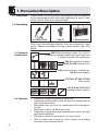
1.2 Unpacking
1 C 5900M
or C 5900M/TM 40
1 SA 61
1 Carrying case
Check that the packaging contains all of the components listed
above. Should anything be missing, please contact your AKG
dealer.
1.3 Optional
Accessories
• MK 9/10 microphone cable: 10 m (30 ft.)
2-conductor shielded cable with 3-pin male and
3-contact female XLR connectors
• TM 40 transmitter module
• W 23, W 3001 windscreens
• H 30 universal elastic suspension,
SA 26 stand adapter
• ST 102A, ST 200, ST 305
floor stands
• N 62, N 66, B 18, B 15
phantom power supplies
1.4 Features
•
•
•
•
•
•
•
12
Frequency response tailored to vocal use.
Integrated wind and pop screen for effective suppression of
pop and breath noise.
Switchable bass cut filter for suppression of low-frequency
rumble.
Selectable 0 dB or +6 dB output level.
Frequency independent supercardioid polar pattern for high
gain before feedback.
Backplate condenser transducer for crisp sound.
Built-in spider type transducer shock mount for handling
and cable noise compensation.
1 Description
•
•
Extremely resilient, spring-steel wire-mesh cap for extra
impact resistance.
Installation slot for optional TM 40 transmitter module.
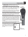
The AKG C 5900M is a supercardioid condenser microphone
designed for vocal use on stage. A slight sensitivity peak
between 3 kHz and 15 kHz provides good intelligibility and will
make your voice cut through the loudest mix on stage.
1.5 C 5900M,
C 5900M/TM 40
A rugged front grill made of spring-steel wire mesh that is
extremely resistant to deformation and a sturdy zinc alloy diecast body effectively protect the microphone and transducer
element from damage on stage and on the road.
A level selector (1) allows you to boost the microphone's output
level by 6 dB to match the signal level to less sensitive inputs.
A switchable bass cut filter (2) (-12 dB/octave from 100 Hz)
effectively reduces low-frequency rumble.
The microphone element uses a proven backplate condenser
transducer. Similar to an anechoic chamber, an absorption ring
of synthetic rubber at the back of the capsule prevents reflections within the capsule that might degrade the frequency
response. An integrated spider type shock mount on the transducer element effectively suppresses handling and cable noise.
An internal windscreen reduces pop, wind, and breath noise to
a minimum.
The C 5900M features a removable connection module with a 3pin XLR connector. You can connect the microphone to both
balanced and unbalanced mixer or amplifier inputs.
1
2
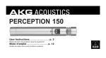
The microphone body has been specifically designed for fatigue-free handling
and ease of use. No matter what microphone technique you use, the microphone will always settle comfortably into
your hand.
Fig. 1:
Ergonomically
optimized shape.
13
1 Description
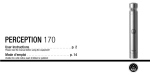
You can easily convert the microphone
into a wireless microphone. All you need
to do is remove the XLR connector module and replace it with an optional TM 40
transmitter module.
Fig. 2: Optional
TM 40 transmitter
module.
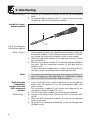
2 Interfacing
2.1 General
Refer to sections
2.2 and 2.3.
The C 5900M is a condenser microphone and therefore needs a
power supply.
The microphone provides a balanced output on a 3-pin male
XLR connector:
Pin 1: ground
Pin 2: hot
Pin 3: return
You can connect the microphone either to a balanced microphone input with or without phantom power or an unbalanced
microphone input.
2.2 Input with
Phantom Power
C 5900M
Phantom
2.3
C 5900M
2.2
Fig. 3: Connecting
to a balanced input.
Refer to fig. 3.
1. Use an XLR cable (e.g., the optional MK 9/10 from AKG) to
connect the microphone to a balanced XLR input with
phantom power.
2. Switch the phantom power on. (Refer to the manual of the
unit to which you connected your microphone.)
2.3 Input with No
Phantom Power
Refer to fig. 3.
1. If your mixer provides no phantom power, connect an
optional AKG phantom power supply (N 62 E, N 66 E, B 18,
B 15) between the microphone and the mixer.
14
2 Interfacing
Using any power supply other than those recommended
by AKG may damage your microphone and will void the
warranty.
Important!
2.4 Unbalanced
Input
C 5900M
Phantom
Fig. 4: Connecting
to an unbalanced
input.
You may connect AKG phantom power supplies to unbalanced
inputs, too.
Refer to fig. 4.
Use a cable with a female XLR connector and TS jack plug:
1. On the XLR connector, use a wire bridge to connect pin 1 to
pin 3 and the cable shield.
2. Connect the inside wire of the cable to pin 2 on the XLR
connector and the tip contact of the jack plug.
Unbalanced cables may pick up interference from stray magnetic fields near power or lighting cables, electric motors, etc.
like an antenna. This may introduce hum or similar noise when
you use a cable that is longer than 16 feet (5 m).
Note:
The optional TM 40 transmitter module allows you to convert
your microphone into a wireless microphone that you can use
with any WMS 40 Series receiver from AKG.
2.5 Optional
TM 40 Transmitter
Module
Start by removing
the XLR connector module:
1
2
1. Open the fixing screw (1).
Fig. 5: Removing
the XLR connector
module.
Refer to fig. 5.
15
2 Interfacing
Refer to fig. 5.
2. Pull the XLR connector module (2) out of the microphone
body.
3. To avoid losing the fixing screw (1), screw it into the threaded hole (3) in the XLR connector module.
Install the transmitter module:
2
1
Fig. 6: Installing the
transmitter module.
Refer to fig. 6.
1. Do not forget to check the condition of the battery inside the
transmitter module. If the battery is dead or there is no battery inside the transmitter module, insert a new battery.
2. Hold the transmitter module (1) to align the contacts (2) with
the microphone.
3. Slide the transmitter module (1) into the microphone body to
the point that the transmitter module (1) will lock with an
audible click.
As the transmitter module locks in place, the electrical connections to the microphone are made automatically.
Note:
For details on inserting, replacing, and testing the battery as
well as setting up and operating the transmitter module
refer to the TM 40 transmitter module manual.
Replacing the
transmitter
module with the
XLR connector
module:
1. Insert a ball point pen, small screwdriver, or similar pointed
object into the opening (1) in the microphone body and
press inward.
The transmitter module (2) will unlock and slide out of the
microphone body for about 0.1 inch.
2. Pull the transmitter module (2) out of the microphone.
3. Unscrew the fixing screw (4) from the XLR connector module (3).
4. Slide the XLR connector module (3) into the microphone
body to the stop.
5. To fix the XLR connector module (3), screw the fixing screw
(4) down firmly.
Refer to fig. 7.
16
2 Interfacing
2
1
4
3
Alternatively, you can remove the transmitter module simply by
pulling it out of the microphone body with just enough force to
unlock it. Make sure not to grasp the transmitter module by the
battery compartment. (If you did, you would only open the battery compartment.)
Fig. 7: Removing
the transmitter
module.
Note:
3 Using Your Microphone
A handheld vocal microphone provides many ways of shaping
the sound of your voice as it is heard over the sound system.
The following sections contain useful hints on how to use your
microphone for best results.
The following sections apply to both the hardwire C 5900M and
the wireless version with an optional TM 40 transmitter module
installed.
3.1 Introduction
Basically, your voice will sound the bigger and mellower, the
closer you hold the microphone to your lips. Moving away from
the microphone will produce a more reverberant, more distant
sound as the microphone will pick more of the room’s reverberation.
You can use this effect to make your voice sound aggressive,
neutral, insinuating, etc. simply by changing your working distance.
Proximity effect is a more or less dramatic boost of low frequencies that occurs when you sing into the microphone from
less than 2 inches. It gives more "body" to your voice and an
intimate, bass-heavy sound.
3.2 Working
Distance and
Proximity Effect
17
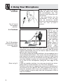
3 Using Your Microphone
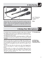
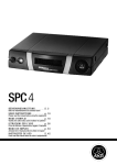
3.3 Angle of
Incidence
Fig. 8: Typical
microphone
position.
3.4 Feedback
Fig. 9: Microphone
placement for maximum gain before
feedback.
Refer to fig. 9.
18
Sing to one side of the microphone or above and across
the microphone’s top. This
provides a well-balanced, natural sound.
If you sing directly into the
microphone, it will not only
pick up excessive breath
noise but also overemphasize
"sss", "sh", "tch", "p", and "t"
sounds.
Feedback is the
result of part of
the sound projected by a speaker
being picked up
by a microphone,
fed to the amplifier, and projected
again
by
the
speaker. Above a
specific volume or
"system
gain"
sett i n g
called
the feedback threshold, the signal starts being regenerated
indefinitely, making the sound system howl and the sound
engineer desperately dive for the master fader to reduce the
volume and stop the howling.
To increase usable gain before feedback, the microphone has a
supercardioid polar pattern. This means that the microphone is
most sensitive to sounds arriving from in front of it (your voice)
while picking up much less of sounds arriving from the sides or
rear (from monitor speakers for instance).main ("FOH") speakers in front of the microphones (along the front edge of the
stage).
If you use monitor speakers, be sure never to point any microphone directly at the monitors, or at the FOH speakers.
Feedback may also be triggered by resonances depending on
the acoustics of the room or hall. With resonances at low frequencies, proximity effect may cause feedback. In this case, it
is often enough to move away from the microphone a little to
stop the feedback.
3 Using Your Microphone
1. Never let more than two
persons share a microphone.
2. Ask your backing vocalists
never to sing more than 35
degrees off the microphone axis.
The microphone is very
insensitive to off-axis
sounds. If the two vocalists were to sing into the
microphone from a wider
angle than 35 degrees,
you may end up bringing up the fader of the microphone
channel far enough to create a feedback problem.
3.5 Backing
Vocals
Fig. 10: Two vocalists sharing a microphone.
4 Cleaning
To clean the surface of the microphone body, use a soft cloth
moistened with water.
4.1 Microphone
Body
1. Unscrew the front grill from the microphone CCW.
2. Remove the windscreen from the from grill and wash the
windscreen in soap suds.
3. Allow the windscreen to dry overnight.
4. Replace the windscreen in the front grill and screw the front
grill on the microphone CW.
4.2 Internal
Windscreen
19
5 Troubleshooting
Possible Cause
Remedy
1. Power to mixer and/or
amplifier is off.
2. Channel or master fader
on mixer, or volume
control on amplifier is at
zero.
3. Microphone is not connected to mixer or
amplifier.
4. Cable connectors are
seated loosely.
5. Cable is defective.
1. Switch power to mixer
or amplifier on.
2. Set channel or master
fader on mixer or volume control on amplifier
to desired level.
3. Connect microphone to
mixer or amplifier.
Problem
No sound.
6.
7.
8.
9.
Distortion.
Microphone sound
becomes duller
by and by.
20
4. Check cable connectors
for secure seat.
5. Check cable and
replace if damaged.
No supply voltage.
6. Switch phantom power
on.
Phantom power supply:
connect to power outlet
or insert battery (batteries).
Check cable and
replace if necessary.
Transmitter module is off 7. Switch transmitter module on.
or muted.
8. Insert new/fully charged
No/dead battery in
battery.
transmitter module.
9. Switch receiver on or
Receiver is off or not
connect to mixer.
connected to mixer.
1. Gain control on mixer or 1. Set gain control to stop
distortion.
transmitter module not
set correctly.
2. Insert 10 dB preattenua2. Mixer input sensitivity
tion pad between microtoo high.
phone cable and input.
• Internal or external
windscreen attenuates
high frequencies when
soiled.
• Clean internal or external windscreen.
6 Specifications
Type:
Polar pattern:
Frequency range:
Sensitivity at 1 kHz:
Impedance:
Recommended load impedance:
Max. SPL for 1%/3% THD:
Equivalent noise level:
Power requirement:
Current consumption:
Connector:
Finish:
Size:
Net/shipping weight:
condenser microphone
supercardioid
20 Hz to 20 kHz
6 mV/Pa (-44 dBV re 1 V/Pa)
≤200 Ω
≥2000 Ω
139/142 dB SPL
17.5 dB (A) (to DIN 45412)
9 to 52 V universal phantom power
approx. 2 mA
3-pin male XLR
matte black
length: 186 mm (7.3 in.)
max. dia.: 50 mm (2 in.)
290 g (10.2 oz.) / 970 g (2.2 lbs.)
This product conforms to EN 50 082-1 provided it is connected to equipment with a CE
sign.
Frequency Response
Polar Diagram
21
Mikrofone
·
Kopfhörer
·
Drahtlosmikrofone
·
Drahtloskopfhörer
·
Kopfsprechgarnituren
·
Akustische
Komponenten
Microphones · Headphones · Wireless Microphones · Wireless Headphones · Headsets · Electroacoustical Components
Microphones · Casques HiFi · Microphones sans fil · Casques sans fil · Micros-casques · Composants acoustiques
Microfoni
·
Cuffie
HiFi
·
Microfoni
senza
filo
·
Cuffie
senza
filo
·
Cuffie-microfono
·
Componenti
acustici
Micrófonos · Auriculares · Micrófonos inalámbricos · Auriculares inalámbricos · Auriculares con micrófono · Componentes acústicos
Microfones · Fones de ouvido · Microfones s/fios · Fones de ouvido s/fios · Microfones de cabeça · Componentes acústicos
Technische Änderungen vorbehalten. Specifications subject to change without notice. Ces caractéristiques sont susceptibles de modifications.
Ci riserviamo il diritto di effettuare modifiche tecniche. Nos reservamos el derecho de introducir modificaciones técnicas. Especificações sujeitas à mudanças sem aviso prévio.
AKG Acoustics GmbH
Lemböckgasse 21–25, P.O.B. 158, A-1230 Vienna/AUSTRIA, Tel: (+43 1) 86 654-0*, Fax: (+43 1) 86 654-7516,
www.akg.com, e-mail: [email protected]
AKG Acoustics GmbH
Bodenseestraße 228, D-81243 München/GERMANY, Tel: (+49 89) 87 16-0, Fax: (+49 89) 87 16-200,
www.akg-acoustics.de, e-mail: [email protected]
AKG ACOUSTICS, U.S.
914 Airpark Center Drive, Nashville, TN 37217, U.S.A., Tel: (+1 615) 620-3800, Fax: (+1 615) 620-3875,
www.akgusa.com, e-mail: [email protected]
For other products and distributors worldwide see our website: www.akg.com
Printed in Austria on recycled paper.
07/03/9100 U 1083