1
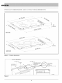
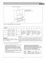
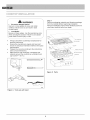
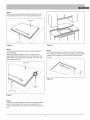
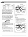
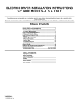
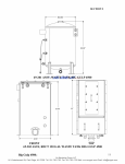
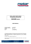
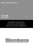
Installation
Distinctive
TM
Electric
Instructions
Cooktop
Models DECT304, DECT365
_D
PJ
eo
_o
Lr)
O
Fran_:is • voir page 1 1
Espa_ol: consuhe
la p6gina 21
Table
of Contents
Page
Special Warnings ..............................................................
WARNING
3
Product Dimensions and Cutout Requirements ............. 4
,,
Important Preparation Suggestions ..................................... 5
Cooktop installation .......................................................... 6
•
Electrical Connections ...................................................... 9
This is the safety alert symbol. This symbol
alerts you to potential hazards that can kill or
hurt you and others.
You can be killed or seriously injured if you
don't follow these instructions.
\,
General information ............................................................. 9
3-Wire branch circuit .........................................................
10
READ AND SAVE THESE iNSTRUCTiONS.
4-Wire branch circuit .........................................................
10
To installer:
Leave these instructions
with the appliance.
To customer:
Retain these instructions
for future reference.
OWNER: Please keep this manual for future reference.
INSTALLER:
Please leave this manual with owner for future reference.
IMPORTANT:
Save these instructions
Pay attention
manual
for the local electrical
to these symbols
inspector
use
present in this
WARNING
,,
You can be killed or seriously injured if you don't
IMMEDIATELY follow instructions.
,,
J
If the information in this manual is not followed
exactly, a fire or explosion may result in
personal injury or death.
Do not store or use gasoline or other
flammable vapors and liquids in the vicinity of
this or any other appliance.
.......
,J
WARNING
Spec[aJ
Please read all instructions
Proper installation is your responsibility.
qualified technician install this cooktop.
Have a
Important:
,,
,,
•
Observe all governing codes and ordinances.
Write clown the model and serial numbers before
installing the cooktop. Both numbers are on the
serial rating plate located on bottom of cooktop
box.
If you receive a damaged product, immediately
contact your dealer or builder. Do not install or use
a damaged appliance. Do not install or use the
appliance if the conduit is damaged.
Before
S_ardn£
_ns_a_adon
WARNING
It is the customer's responsibility to contact a
qualified electrical installer. To assure that the
electrical installation is Adequate and in
conformity with national electrical code:
ANSI/NFPA 70-latest edition** or CSA standards
C22.1-94, Canadian Electrical Code, part No.0M91 -latest edition*** and all local codes and
ordinances.
Wam_ngs
before
Copies
using this appliance
of the standards
listed may be obtained
** National Fire Protection Association
Quincy, Massachusetts
02269
*** CSA International
OH 44131-5575
from:
One Batterymarch
8501 East Pleasant
Valley
Park
Rd. Cleveland,
To eliminate the risk of burns by reaching over
heated surface units, cabinet storage space located
above the surface units should be avoided. If he
cabinet storage is to be provided, the risk can be
reduced by installing a range hood that projects
horizontally a minimum of 5" (12,7 cm) beyond the
bottom of cabinet.
m)
DECT304
2_
J(5,18cm)
DECT365
Figure
1. Chassis
dimensions
CUTOUT
DiMENSiONS
WIDTH OF CUT
A
SEE NOTE
R
1-1/2" (3.8 cm)
MIN CLEARANCE
DEPTH
OF CUT
B
FROM EDGE OF CUTOUT
AND FRONT EDGE OF
Hole in cabinet
floor for conduit
COUNTERTOP
1" (2,5cm)
routing:
3 1/2" (9 cm)
deep x 2 1/2" (6.5 cm) wide
JNST 035-2
Figure 2
CABINET REQUIREMENTS
G
WALL COVERING CABINETS,
AND COUNTERTOP MUST
WITHSTAND
HEAT UP TO 200°F (93°C)
INST 023-2
Fiaure
3. Cabinet
CUTOUT
WIDTH
dimensions
A
and
reauirements
B
C
D
E
F
G
28-11/16"
30" (76.2cm)
i 19-1/4"
(72.9 cm) to I(49.0 cm) to
28 15/16"
i 19-9/16"
(73.5 cm)
34-1/16"
36" (91.4 cm)
(76.2 cm) min
(49.7 cm)
18" (45.7 cm)
min height from
countertop to
nearest cabinet
i 19-1/4"
(86,5 cm) to (49.0 cm) to
34-5/16"
i 19-9/16"
(87.2 cm)
130"
36"
(91.4 cm) min
on either side
of unit
30" (76.2 cm)
min. (see note*)
clearance from
countertop to
unprotected
overhead
surface
2" (5 cm) min
clearance from
cutout to side
wall on the left
and right of the
unit
13" (33 cm)
depth of
unprotected
overhead
cabinets
i(49.7 cm)
* NOTE
IMPORTANT
Under the cooktop it is necessary to install a
partition, spaced from the bottom of the appliance
as shown in figure 2-3.
_mportant
1.
2.
3.
4.
Preparation
24" (61 cm) min. clearance if bottom of wood or metal cabinets is protected
by not less than 1/4" (0.6 cm) flame retardant millboard covered with no less
than No. 28 MSG sheet steel 0.015" (0.04 cm)stainless
steel, or 0.024"
(0.06 cm) aluminum or 0.020" (0.05cm) copper. 30"(76.2 cm) min. clearance
between top of cooking platform and bottom of unprotected wood or metal
cabinet
Suggestions
Chamfer all exposed edges of decorative laminate
to prevent damage from chipping.
Radius corners of cutout and file to Insure
smooth edges and prevent corner cracking.
Recommend
1/4"or 3/8"diameter drill in each
corner.
Rough edges, inside corners which have not been
rounded and forced fits can contribute to cracking
of the countertop laminate.
This cooktop is not compatible with a raised vent.
This cooktop has been designed with wide
tolerances
of cut-out to cover possible
replacement
with other brands. We recommend
to
that you consider the minimum dimension
of cutout size in the case of new Installation.
Some cutout sizes for possible replacements:
Dim .
Inches
cm
, 30"
28-15/16" x 19-9/16"
73,5 x 49,7
, 36"
34-5/16" x 19-9/16"
87,2 x 49,7
_00
10
_ Ho
[)%LLA
0_
Step 1
Remove packaging materials and literature package
from the cooktop before beginning installation.
Remove installation manual from literature pack and
read them carefully before you begin.
WARNING
=
Excessive Weight Hazard
Use two or more people to move and install
cooktop. Failure to do so can result in back
or other injury.
•
Cut Hazard
Beware of sharp edges. Use the polystyrene ends
when carrying the product. Failure to use caution
•
o
•
,,
Always consult the countertop manufacturer for
specific instructions.
Ensure the countertop is square and level and
ensure no structural members interfere with space
requirements.
Prepare the cut-out according to the instructions
(see cut-out dimensions).
Make sure the wall coverings, countertop and
cabinets around the cooktop can withstand heat
(up to 200 °F / 93 °C).
COOKTOP_.
INTRENAL PACKAGING
BOTTOM PACKAGING
..... J
CARDBOARD
/
/
/
(((,'
Figure
O06A
Figure
4. Tools
you will need
5. Parts
Step 2
Place a towel or table cloth onto the counter top. Lay
the cooktop upside down onto the protected surface.
BURNER BOX
TABLE CLOTH
Figure 8
Figure 6
Step 3
A foam tape is provided to seal the cooktop edges to
the countertop.
Apply tape approximately 1/16" (1.5 mm) from the
glass edge to the underside of the cooktop glass. Use
tape around the entire glass perimeter. Cut off excess
where tape ends butt.
Step 5
Four clamp brackets are provided to clamp the cooktop to
the countertop. Tighten screws just enough to hold brackets
in place when cooktop is put into cutout. Tighten screws
securely.
BURNER BOX
Figure 9
FOAM TAPE
SEAL
COOKTOP
GLASS
Figure 7
Step 4
Insert the cooktop centered into the cutout opening. Make
sure the front edge of the counter top is parallel to the
cooktop. Make final check that all required clearances are
met.
CONDUIT
LOCATIONS
OF ALUMINUM
REFLECTIVE TAPE
OPENING
A: 12" (30,5 cm) MIN FROM
BOTTOM OF COUNTERTOP
AND ADJACENT CABINET
(RIGHT SIDE)
f
I
TAPE TOP AND
VERTICAL SIDES
OF ;UTOUT
SOLID SURFACE
COUNTERTOP
INSTALLATION
INST 005-2
Figure 11
f
INST
..................................................................................................................
030-2
WARNING
Figure 10
THE CONDUIT
IS 4 FEET LONG
The junction box, must be located where it will
allow considerable slack in the conduit for
serviceability.
Important:
•
,,
For solid surface material installations such as
Surel TM and Corian ®, consult with solid surface
manufacturer. Apply heat reflective tape such as
Scotch® Aluminum Foil Tape #425 or #427
around the cutout so that it folds over on the top
and sides.
Do not wrap the tape underneath the cooktop.
Be sure the tape extends beyond the outermost
flange of the cooktop. All corners should be
covered with tape.
Disconnect
power
before servicing the product.
Failure to do so could result in death or
electrical shock.
®eneral
information
s ...........
The flexible conduit (supplied) 4 feet long (123 cm)
located at the right rear of the cooktop bottom box
should be connected directly to junction box. Do not
cut or lengthen the conduit. A U.L - or CSA - listed
conduit connector must be provided at each end of the
power supply cable (at the cooktop and at the junction
box.) A time delay fuse or circuit breaker is
recommended. Do not ground to a gas pipe.
Do not have a fuse in the grounding or neutral circuit.
Fuse both supply (phase) lines.
WARNING
*
The DECT series
models
WARNING
may be powered
at 240V or 208V.
Improper connection
Lthe
This cooktop does not require a neutral connection. If
the cooktop is to be completely enclosed in a cabinet,
feed the cooktop cable through the opening in the
cabinet. Make the electrical connection following the
appropriate steps for your installation.
Your cooktop must be connected to the proper
electrical voltage and frequency as specified in the
table on the right.
of aluminum
house wiring to
copper leads can result in a serious problem,
Power Supply
Model
30"
DECT304
36"
DECT365
240 V 60 Hz
208 V 60 Hz
6,7kW
28A
5,03kW
I
9,4kW
39A
7,06kW
I
Connect
with copper
wire only
If the house has aluminum wiring, follow the
procedure below:
1.
2.
Connect the aluminum wiring to the copper wire
by using special connectors designed and
Underwriters Laboratories-listed
for joining copper
to aluminum. Follow the electrical connector
manufacturer's recommended procedure.
Aluminum/copper
connection must conform with
local codes and industry- accepted wiring
practices.
Approval
code
24A
514T40NA
34A
514V50NC
I
National Fire Protection Association
Batter/march
Park Quincy, Massachusetts
Figure 12. Location of serial tag
/
,_
02269
A three-wire, single phase, 240 Volt 60 cycle electrical
system (properly circuit protected to meet Local
Codes of NFPA No.70) must be provided. Unit must
be properly grounded in accordance with local wiring
code. The chart below recommends the minimum
circuit protector and wire size if the appliance is the
only unit on the circuit. If smaller sizes of wire are
used, the unit efficiency will be reduced and a fire
hazard may be created. It is advisable that the
electrical wiring and hookup be accomplished by a
competent electrician.
Recommended
kW Rating on
serial plate
Minimum
Circuit protection
in amperes
3-WIRE CABLE
FROM POWER
SUPPLY
Wire size
(AWG)
0-4.8
20
12
4.9-6.9
30
10
7.0-9.9
40
8
10.0-11.9
50
8
12.0-14.9
60
6
RED WIRES
w
WIRE
BARE OR GREEN
WIRES
3=WIRE CABLE
FROM COOKTOP
/
BLACK WlRES
U.L.-OR CSA-MSTED
CONDUIT CONNECTOR
Where local codes permit connecting the frame-ground
conductor
to the neutral (white) junction box wire.
(Not used for Canadian installations)
This appliance is manufactured with a green ground
wire connected to the cooktop chassis. After making
sure that the power has been turned off, connect the
flexible conduit from the cooktop to the junction box
using a U.L. listed conduit connector. Figures 13 and
14 and the instructions provided below present the
most common way of connecting the cooktops. Your
local codes and ordinances, of course, take
precedence over these instructions. Complete
electrical connections according to local codes and
ordinances.
INST031-2
Figure 13.
4oWire
branch
circuit
Refer to figure 14:
1.
Connect the green ground wire from the cooktop
to the ground wire in the junction box (bare or
green colored wire).
2.
Connect the red and black leads from the cooktop
to the corresponding leads in the junction box.
Connect the white wire from the cooktop to the
neutral (gray or white) wire in the junction box.
3.
4.
to
Terminate and insulate the neutral (gray or white
colored wire) in the junction box.
RED WIRES
JUNCTION
Grounding through the neutral conductor is prohibited
for new branch-circuit installations (1996 NEC);
mobile homes; and recreational vehicles, or in an area
where local codes prohibit grounding through the
neutral conductor.
3,,,,,,Wirebranch
BOX
7
Be sure your appliance is properly installed and
grounded by a qualified technician.
Ask your
dealer to recommend
a qualified technician
or an
authorized
repair service. This cooktop does not
require a neutral connection,
if the cooktop is to
be completely
enclosed in a cabinet, feed the
cooktop cable through the opening in the cabinet.
Make the electrical connection
following
the
appropriate
steps for your installation.
Risk of Electric Shock, frame grounded
neutral of appliance through a link.
JUNCTION
BOX
WHITE WiRE
circuit
Where local codes allow the connection of ground
wire from the cooktop to the branch circuit neutral wire
(gray or white colored wire) proceed as follows (see
figure 13).
1. If local codes permit, connect the green GROUND
wire from the cooktop to the branch circuit neutral
wire (gray or white colored wire).
2. Connect the red and black leads from the cooktop
to the corresponding leads in the junction box.
BARE OR GREEN
WIRES
3-WIRE CABLE
FROM COOKTOP
TWIST-ON
CONNECTOR
BLACK
INST 032-2
CONDUIT
Figure 14.
10
WIRES
U.L.-OR CSA-LISTED
CONNECTOR
%3
©
O
O
oO
LO
C_d
C3
O'.
o
_J
©
©
The Life of the Kitchen?
Dacor • 600 Anton Blvd. Suite 1000 Costa Mesa, CA 92626 • Phone: (800) 793-0093 • Fax: (626)403-3130
• www.dacor.com