1
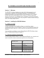
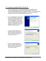
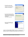
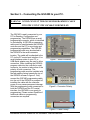
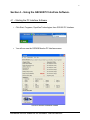
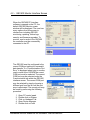
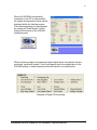
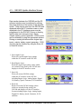
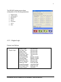
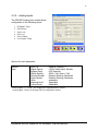
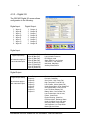
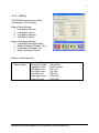
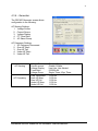
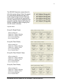
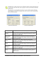
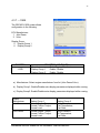
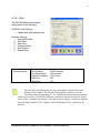
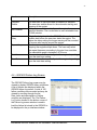
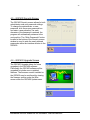
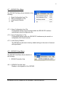
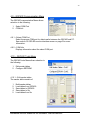
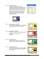
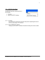
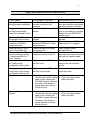
GSC400
PC INTERFACE
SOFTWARE MANUAL
Installation and User Manual for the
GSC400 PC Software Interface
File: GSC400ConfigRev1.0.doc
Feb., 2006
2
Thank You for purchasing this DynaGen product
Please read manual before programming Unit
End-user Agreement for GSC400 PC Interface software.
GRANT OF RIGHTS
DynaGen Technologies grants you the following non-exclusive rights:
You may install and use the enclosed software product on your computer for reading
and configuration of the GSC400 engine controller.
You may not reverse- engineer, decompile, or disassemble the software product, except
and only to the extent that applicable law notwithstanding this limitation expressly
permits such activity.
You may not rent or lease the software product.
LIMITATION OF LIABILITY
NO LIABILITY FOR CONSEQUENTIAL DAMAGES. To the maximum extent permitted
by applicable law, in no event shall DynaGen Technologies or its suppliers be liable for
any damages whatsoever (including, without limitation, damages for loss of business
profit, business interruption, loss of business information, or any other pecuniary loss)
arising out of the use of, or inability to use this software product.
.
We welcome your comments and suggestions. Please contact us at:
DynaGen Technologies Inc.
Phone: 1-888-396-2436
(902) 562 0133
Fax: (902) 567 0633
Email: [email protected]
WEB SITE: www.dynagen.ca
Installation and User Manual for the GSC400 PC Software Interface
3
Table of Contents
1.0 Welcome
4
2.0 Installing the GSC400 software
2.1 Before you begin
2.2 Minimum hardware requirements
2.3 Installing on Windows
4
3.0 Connecting the GSC400 to your PC
7
4.0 Using the GSC400 PC interface software
4.01 Starting the PC interface software
4.02 GSC400 monitor interface screen
4.03 GSC400 update interface screen
4.3.1 Engine logic
4.3.2 Analog inputs
4.3.3 Digital I/O
4.3.4 Batttery
4.3.5 Speed
4.3.6 Generator
4.3.7 J1939
4.3.8 Misc
4.04 GSC400 failure log screen
4.05 GSC400 security screen
4.06 GSC400 upgrade screen
4.07 GSC400 file menu
4.7.1 Open configuration from file
4.7.2 Save configuration to file
4.7.3 Load factory Defaults
4.08 GSC400 view menu
4.09 GSC400 communication menu
4.9.1 Select COM port
4.9.2 COM information
4.10 GSC400 tools menu
4.11 GSC400 help menu
5.0 GSC400 Troubleshooting Guide
Installation and User Manual for the GSC400 PC Software Interface
8
8
9
11
26
28
28
29
29
30
30
32
33
4
PC INTERFACE SOFTWARE INSTRUCTIONS
Section 1 – Welcome
The GSC400 PC software interface is a program which allows programming and
customization to DynaGen’s GSC400 Engine Controllers. The GSC400 can be
programmed manually via front panel buttons OR with the easy-to-use PC software
interface which allows customization of inputs, outputs; AC sensing, engine logic
settings, and much more. The GSC400 may be configured for common and advanced
parameters from the front panel buttons or by using the PC software interface allowing a
quick, user friendly display interface.
Section 2 – Installing the GSC400 Software
2.1 – Before you begin
In order to install and use the DynaGen software, you should have a basic
understanding of how to use your computer. If you do not, we recommend that you ask
someone who does to help you, or that you read the user manual that came with your
computer.
If you encounter any problems or errors while installing the GSC400 software, please
refer to Troubleshooting Guidelines On page 33.
2.2 – Minimum Hardware Requirements
For the DynaGen GSC400 software to work reliably and efficiently, your computer must
meet or exceed the minimum requirements specified in the following table:
Operating System
Windows 98SE, 2000, ME,
XP.
Processor
Pentium or equivalent
processor
Memory
64 MB RAM
Hard Drive
20 MB Free Disk Space
Video card display
256 colors at 1024x768
Peripherals
CD-ROM Drive
Port
RS232 Serial (COM) Port
Or USB (with adapter)*
*USB-Serial adapter required
Installation and User Manual for the GSC400 PC Software Interface
5
2.3 – Installing on Windows 98SE, 2000, ME, XP.
1. Exit all open applications, close any open windows, and disable any virus
protection software before installing the GSC400 software. (Consult the
instructions that came with your virus protection software.) If you have a previous
version of the GSC400 PC Interface installed on your PC then you should
uninstall the current version before installing the newer one.
2. Insert the GSC400 PC Interface CD
into your CD-ROM drive. After a few
seconds the interface setup screen
should be displayed. Click next to
continue installation. If the installation
does not start automatically, double
click the “my computer” icon on your
desktop, and then double-click the
DynaGen PC Interface icon.
3. You are now presented with the
destination screen. Click the next
button to install the software to the
default location. Click browse to
choose a new location.
4. You are now presented with the
Start menu screen. Click the next
button to install the software to the
default location. Click browse to
choose a new location.
Installation and User Manual for the GSC400 PC Software Interface
6
5. Click Install to continue setup
installation which will install the
program to the confirmed locations.
Click Back to make changes.
6. A process bar displays the software
being copied to your hard drive. This
may take several minutes depending
upon the speed of your computer and
CD-ROM drive.
Press Cancel to abort setup.
7. Upon successful installation, the
following screen will be displayed.
Click finished
You have successfully installed the GSC400 PC interface. If you have encountered any
problems or errors while installing the software, please refer to Troubleshooting
Guidelines on page 33 or call DynaGen technical support Hot Line at 1-902-562-0133.
Installation and User Manual for the GSC400 PC Software Interface
7
Section 3 – Connecting the GSC400 to your PC.
WARNING: NEVER CONNECT THE GSC400 PROGRAMMING CABLE
INTO THE UNIT IF THE GSC400 IS POWERED ON.
The GSC400 is easily connected to your
PC for Reading, Configuration and
programming. The GSC400 has a serial
programming connector, which is identified
on the labeling. A GSC400 programming
cable must be used between the GSC400
controller and the PC for monitoring and
programming capabilities. The GSC400
programming cable may be attached to
the GSC400 in the serial connector
location. The cable will be attached to the
PC via the PC’s serial port interface. If no
serial interface exists on your PC, a
USB-Serial adapter may be used to allow
connection. When installing the GSC400
program cable into the controller’s serial
connector, be certain to take notice of the
polarity of both connectors. The
programming cable must be installed with
the red marking facing towards the top of
the GSC400 as seen in figure 3. Only
connect the GSC400 programming cable
into the unit if the GSC400 is powered off,
installing the cable with the controller
power on may cause permanent damage.
With the programming cable connected to
both the GSC400 and the PC’s serial
interface, the GSC400 is now ready for
programming. Please contact DynaGen if
additional cables or programming
connectors are required.
Figure1 – Serial Connector
Figure2 – Connector Polarity
Figure3 – Cable Polarity
Installation and User Manual for the GSC400 PC Software Interface
8
Section 4 – Using the GSC400 PC Interface Software.
4.1 – Starting the PC Interface Software
1. Click Start, Programs, DynaGen Technologies, then GSC400 PC Interface.
2.
You will now see the GSC400 Monitor PC Interface screen.
GSC400 Monitor Interface Screen
Installation and User Manual for the GSC400 PC Software Interface
9
4.2 – GSC400 Monitor Interface Screen
When the GSC400 PC Interface
software is opened on the PC, the
default GSC400 Monitor screen
window will be displayed. The user has
many options from this screen to
choose from including GSC400
monitoring, updating, failure logs,
security and firmware upgrades. To
monitor, read or write to the GSC400
the controller must be successfully
connected to the PC.
The GSC400 must be configured to the
correct COM port setting for successful
data transfer. If a “Communications Port
Error” is displayed when tying to monitor,
read or write to the GSC400 the correct
COM port must be selected. The correct
COM port may be selected under the
Communication tab within the GSC400
interface screen. The correct COM port
may be selected by simply choosing a
different port from the list until the port
error is eliminated. The correct port may
be found by performing the following
procedure.
1.
2.
3.
4.
5.
Open PC control panel
Double click on System
Click on Hardware Tab
Open Device Manager
Double click on Ports
Installation and User Manual for the GSC400 PC Software Interface
10
When the GSC400 is successfully
connected to the PC for data transfer,
the engine and generator status may be
displayed within the interface screen.
The monitoring status can be displayed
by clicking the “Start Monitor” button
located at the bottom of the GSC400
interface screen.
When monitoring engine and generator status digital inputs and outputs are also
monitored. Inputs and outputs 1 thru 8 will depend upon the configuration of the
GSC400 settings. A check represents that the function is currently active.
Example of Digital I/O monitoring
Installation and User Manual for the GSC400 PC Software Interface
11
4.3 – GSC400 Update Interface Screen
Data transfer between the GSC400 and the PC
software interface may be achieved by clicking
the proper buttons on the bottom of the interface
screen. Data may be read from the GSC400 and
displayed within the PC interface screen or data
displayed in the PC interface screen may be
programmed to the GSC400. Storing or reading
specific data such as engine logic, inputs,
outputs, battery, speed, generator, J1939 or misc
can be obtained by using the appropriate buttons.
Storing or reading all data such as engine logic,
inputs, outputs, battery, speed, generator, J1939
and misc can be obtained by using the Store All
or Read All buttons.
1. Store engine Logic:
Writes the current engine logic settings
within the PC interface to the GSC400.
2. Read Engine Logic:
Reads the engine logic setting values which
are currently being used by the GSC400 and
displays it to the PC interface screen.
3. Store All:
Writes all current GSC400 settings
within the PC interface to the GSC400
including Engine Logic, Analog Inputs, Digital
I/O, Battery, Speed, Generator, J1939 and Misc.
4. Read All:
Reads all current GSC400 settings values
which are currently being used by the
GSC400 and displays it to the PC interface
Screen including Engine Logic, Analog Inputs,
Digital I/O, Battery, Speed, Generator, J1939
and Misc.
Installation and User Manual for the GSC400 PC Software Interface
12
The GSC400 Update screen allows
configuration to the following parameters:
1.
2.
3.
4.
5.
6.
7.
8.
Engine Logic
Analog Inputs
Digital I/O
Battery
Speed
Generator
J1939
Misc
4.3.1 – Engine Logic
Engine Logic Settings:
Engine Logic
Delay to Start
Pre-heat Time
Crank Time
MidHeat Time
Crank Rest Time
Crank Attempts
Fuel Crank Rest
False Restart
Post-Heat Time
ETS On Duration
Warm-up Time
Crank Disconnect
Cool Down Delay
Crank Oil pres
0-60 seconds
0-60 seconds
3-60 seconds
0-60 seconds
1-60 seconds
1-60
Disable, Enable
Disable, Enable
0-60 seconds
0-30 seconds
0-600 seconds
100-2000 RPM
0-600 seconds
0-90 KPa
Installation and User Manual for the GSC400 PC Software Interface
13
Function
Description
Delay to Start
The time in seconds that the GSC400 will wait before
starting the generator.
Time in seconds that the GSC400 will preheat the engine.
Preheat occurs before the engine cranking cycle.
Time in seconds the GSC400 will continue to crank the
generator. The controller will engage the flywheel until
engine start or the crank time expires.
Time in seconds that the GSC400 will preheat the engine.
Midheat occurs during the engine cranking cycle
Time in seconds the GSC400 will wait between crank
attempts. If engine starting is unsuccessful after the
specific crank time, the starter will disengage for a specific
time period.
The number of crank attempts the GSC400 will perform
before going into over crack failure.
This enables an energized fuel output while the controller is
in rest time.
With this option enabled, when the engine goes into failure
before the oil bypass time has passed, the GSC400 will reattempt to start the generator.
Time in seconds that the GSC400 will preheat the engine.
Post-heat occurs during the initial stage of engine run.
Energize to stop. This output controls the fuel solenoid.
Time in seconds in order to allow the generator
sufficient time to warm up. This option must be enable in
order to be used.
The frequency at which the GSC400 will disengage the
crank, keeping the fuel on to run the generator.
Time in seconds the GSC400 will wait before shutting he
generator down under a no load condition in order to allow
engine cool down.
This is the oil pressure which is exceeded during cranking.
Pressure: Used for locked rotor detection.
Pre-heat Time
Crank Time
MidHeat Time
Crank Rest Time
Crank Attempts
Fuel Crank Rest
False Restart
Post-Heat Time
ETS On Duration
Warm-up Time
Crank Disconnect
Cool Down Delay
Crank Oil pres
Installation and User Manual for the GSC400 PC Software Interface
14
4.3.2 – Analog Inputs
The GSC400 Analog Input screen allows
configuration to the following inputs:
1.
2.
3.
4.
5.
6.
Hi Engine Temp
Oil Pressure
Fuel Level
Oil Level
Fuel in Basin
Low Engine Temp
Options for each parameter:
Specific
Input
Input Pin
Reserve, Analog 2-7*
Signal Source
J1939, Switch input, Sender
Bypass Delay
0-60 Seconds
Switch Setting
GND = Fail, Open = Fail
Shorted Sender
Disable, Warning, Shutdown
Open Sender
Disable, Warning, Shutdown
Units
selectable
Warning Level
Adjustable
Failure Level
Adjustable
*Analog inputs 2, 5, 6 and 7 are designed for high impedance senders.
Analog inputs 3 and 4 are designed for low impedance senders.
Installation and User Manual for the GSC400 PC Software Interface
15
Function
Input Pin
Signal Source
Bypass Delay
Switch Setting
Shorted Sender
Open Sender
Units
Warning Level
Failure Level
Description
Input 2-7 may be configured to a specific input. A specific
function can be assigned to more then one input pin to
allow a greater current output. If using a sender be careful
to select a Low or High input impedance location to
correspond to the sender specifications. Reserve may be
selected to configure proper setting without assigning an
active input.
How to obtain an engine failure.
The J1939 interface may be selected for a J1939 compliant
engine. The switch input may be selected for a mechanical
switch gauge types. Senders may be selected for electronic
gauge types.
When to recognize an engine failure. Bypass delay is the
time in seconds the GSC400 will wait after crank success
before checking engine for a failure input.
When the Switch Input is selected as the signal source, the
switch setting can be configured for a ground or open
failure. Gnd means that ground would be a failure, +BAT
would be “Engine OK”. Open means that open switch
contacts would be “Failure”, and closed switch contacts
would be a “Engine OK”.
When the Sender Input is selected as the signal source, a
shorted sender can display a warning, shutdown the
engine or be set to have no effect (disabled).
When the Sender Input is selected as the signal source, an
open sender can display a warning, shutdown the engine
or be set to have no effect (disable).
How to display warning and failure level values.
The value when using an electronic sender or J1939 input,
to initiating a warning.
The value when using an electronic sender or J1939 input,
to initiating a Failure.
Installation and User Manual for the GSC400 PC Software Interface
16
4.3.3 – Digital I/O
The GSC400 Digital I/O screen allows
configuration to the following:
Digital Input:
1. Input A
2. Input B
3. Input C
4. Input D
5. Input E
6. Input F
7. Input G
8. Input H
Digital Output:
1. Output A
2. Output B
3. Output C
4. Output D
5. Output E
6. Output F
7. Output G
8. Output H
Digital Input:
Digital Input Setup
All selections apply to
each individual input
Input A (Bat=Fail)
Input B (Bat=Fail)
Input C (Bat=Fail)
Input D (Bat=Fail)
Input E (Gnd=Fail)
Input F (Gnd=Fail)
Input G (Gnd=Fail)
Input H (Gnd=Fail)
Disable, Low Air Pressure
Low Hydraulic Pressure,
EPS Supply Load
Alarm Silence, Low Coolant,
Volt Select 1, Volt Select 2,
Idle Mode, Start/Stop
Auxilary Warn/Failure
Extra Relay
Output A
Output B
Output C
Output D
Output E
Output F
Output G
Output H
Disable, Warm-Up, ETS,
Pre-heat, Cooldown,
Over Crank , High Temp Fail ,
High Temp warn, Low Oil Fail ,
Low Oil warn, Under Speed Fail,
Under Speed Warn, Over Speed Fail
Over Speed Warn, Low Fuel Fail
Low Fuel Warn, Battery Fail,
Battery Warn, Low Coolant Fail,
Low Coolant warn, Not in Auto,
Failure, Crank Rest,
Engine Running, Crank On,
Exerciser Alarm, Recharge Alarm
Under Volt Warn, Over volt warn,
Over Amp Warn, Fuel in Basin,
Volt Regulator, Low Temp Warn.
Back Light, Aux Warn.
Digital Output:
Digital Output Setup
All selections apply to
each individual output
Installation and User Manual for the GSC400 PC Software Interface
17
4.3.4 – Battery
The GSC400 Battery screen allows
configuration to the following:
Battery Status Settings:
1. Low Battery Warning
2. Low Battery Failure
3. High Battery Warning
4. High Battery Failure
Battery Recharging Settings:
1. Low Battery Recharge Enable
2. Battery Recharge PreAlarm Time
3. Low Battery Recharge Level
4. Battery Recharge Duration
Battery setup Parameters:
Battery Setup
Low Auto Charge
Charge Pre-Alarm
Charge Duration
Recharge Level
Low Warn Level
Low Fail Level
High Warn Level
High Fail Level
Disable, enable
1-60 minutes
10-240 minutes
7-24 volts
7-24 volts
7-24 volts
12-32 volts
12-32 volts
Installation and User Manual for the GSC400 PC Software Interface
18
Function
Description
Low Battery
Warning
The battery voltage level to be detected as a low voltage to
sound or display a warning to the user that the battery’s
voltage level has reached a specific value.
The battery voltage level to be detected as a low voltage
displaying to the user that the battery’s voltage level has
reached a specific value requiring an engine start for
recharging.
The battery voltage level to be detected as a high voltage
to sound or display a warning to the user that the battery’s
voltage level has reached a specific value.
The battery voltage level to be detected as a high voltage
displaying to the user that the battery’s voltage level has
reached a specific value requiring an engine start stop
when recharging.
Low battery recharge enabled allows for the automatic
starting of the engine in low battery conditions. The engine
will run to charge the battery.
Recharge pre-alarm allows for the automatic warning of the
engine starting in low battery conditions. The alarm will
sound to warn of a low battery condition and that the
engine will be starting.
The level which a low battery will be charged to when
requiring charging, not exceeding the charge duration.
Recharge duration is the number of minutes the engine will
run to charge a low battery.
Low Battery
Failure
High Battery
Warning
High Battery
Failure
Low Battery
Recharge Enable
Battery Recharge
PreAlarm Time
Low Battery
Recharge Level
Battery Recharge
Duration
Installation and User Manual for the GSC400 PC Software Interface
19
4.3.5 – Speed
The GSC400 Battery screen allows
configuration to the following:
Speed Sensing Configuration:
1. Signal Source
2. Rated Frequency
3. Rated Speed
Speed Sensing Settings:
1. Over Speed Warning
2. Under Speed Warning
3. Over Speed Failure
4. Under Speed Failure
Spd Sensing
Signal Source
Rated Freq
Rated RPM
Over Speed Warn
Over Speed Fail
Under Speed
Warn
Under Speed Fail
J1939, Mag pickup
10-9990 Hz
200-4000 RPM
100-5000 RPM
100-5000 RPM
100-5000 RPM
100-5000 RPM
Installation and User Manual for the GSC400 PC Software Interface
20
Function
Description
Signal Source
How to recognize engine speed. The J1939 interface may
be selected for a J1939 compliant engine. The magnetic
pickup option may be selected for speed sensing from the
engine flywheel. Generator output option may be selected
for speed sensing directly from the Generator output.
Normal running frequency of the engine.
Used to calculate engine speed.
Normal running speed of the engine.
Used to calculate engine speed.
When the engine is running the RPM level is measured,
the GSC400 can be configured for a choosing failure
warning value. This warning value is the value in RPM
which the controller will recognize if the RPM level exceeds
the setting and sound an audio alert.
When the engine is running the RPM level is measured,
the GSC400 can be configured for a choosing failure
warning value. This warning value is the value in RPM
which the controller will recognize if the RPM level goes
beneath the setting and sound an audio alert.
When the engine is running the RPM level is measured,
the GSC400 can be configured for a choosing failure value.
The Failure value is the value in RPM which the controller
will recognize a failure and shut down the engine.
When the engine is running the RPM level is measured,
the GSC400 can be configured for a choosing failure value.
The Failure value is the value in RPM which the controller
will recognize a failure and shut down the engine.
Rated Frequency
Rated Speed
Over Speed
Warning
Under Speed
Warning
Over Speed
Failure
Under Speed
Failure
Installation and User Manual for the GSC400 PC Software Interface
21
4.3.6 – Generator
The GSC400 Generator screen allows
configuration to the following:
AC Sensing Settings:
1. Voltage Source
2. Current Source
3. Voltage Display
4. CT Turns Ratio
5. AC Select Group
AC Frequency Settings:
1. AC Frequency Disconnect
2. Over HZ Warn
3. Over HZ Fail
4. Under HZ Warn
5. Under HZ Fail
AC Sensing
AC Frequency
Voltage Source
Current source
Voltage Display
Turns Ratio
Voltage Group
Freq. Disconnect
Over HZ Warn
Over HZ Fail
Under HZ Warn
Under HZ Fail
Disable, Wye
Disable, Enable
Line-Line, Line-Neutral
5-5000A:5A
Single, Three, Wye, Three
1-100 Hz
1-100 Hz
1-100 Hz
1-100 Hz
1-100 Hz
Installation and User Manual for the GSC400 PC Software Interface
22
Function
Description
Voltage Source
How to recognize the AC power source.
The disable option may be selected if no AC power source
is being monitored. The Wye or Delta option may be
selected for AC voltage monitoring.
Allows monitoring of the current draw on the engine.
The enable option may be selected for monitoring the
amount of current being draw from the engine. The disable
option may be selected if no current monitoring is required.
Select the AC power system type line-line or line-neutral.
Current source
Voltage Display
Turns Ratio
Freq. Disconnect
Over HZ Warn
Over HZ Fail
Under Hz Warn
Under HZ Fail
The turns ratio is user adjustable and must match the
current CT being used. The correct value may be seen on
the current CT and must enter the value in the correct
format as XA:5A where X is the setting enter from the CT.
This is the frequency at which the GSC400 will disengage
the crank, keeping the fuel on to run the generator.
When the engine is running the frequency level is
measured, the GSC400 can be configured for a choosing
failure warning value. This warning value is the value in HZ
which the controller will recognize if the frequency level
exceeds the setting and sound an audio alert.
When the engine is running the frequeny level is
measured, the GSC400 can be configured for a choosing
failure value. The Failure value is the value in HZ which the
controller will recognize a failure and shut down the engine.
When the engine is running the frequeny level is
measured, the GSC400 can be configured for a choosing
failure warning value. This warning value is the value in HZ
which the controller will recognize if the frequeny level goes
beneath the setting and sound an audio alert.
When the engine is running the frequency level is
measured, the GSC400 can be configured for a choosing
failure value. The Failure value is the value in HZ which the
controller will recognize a failure and shut down the engine.
Installation and User Manual for the GSC400 PC Software Interface
23
The GSC400 Generator screen allows for
AC select group settings. Select the proper
AC group which matches the type of AC
power source being monitored. Although
only one AC source may be monitored at
one time, settings may be configured for all
groups through the setpoint tab to allow for
quicker compatibility when changing from
one AC source to another.
Setpoint Menu:
Group #1 (Single Phase)
Allows settings for:
Under/Over Voltage Warning
Under/Over Voltage Failure
Over Current Warning
Over Current Failure
Group #2 (Three Phase)
Allows settings for:
Under/Over Voltage Warning
Under/Over Voltage Failure
Over Current Warning
Over Current Failure
Group #3 (Three Phase Hi Wye)
Allows settings for:
Under/Over Voltage Warning
Under/Over Voltage Failure
Over Current Warning
Over Current Failure
Group #4 (Three Phase)
Allows settings for:
Under/Over Voltage Warning
Under/Over Voltage Failure
Over Current Warning
Over Current Failure
Installation and User Manual for the GSC400 PC Software Interface
24
Although all AC voltage groups may be configured within the setpoint menu and wrote
to the GSC400 at the same time, only one group at a time may be monitored within the
settings menu.
This procedure is recommended when multi AC systems will be monitored allowing
multi settings to be entered for all groups which can be used for on the fly monitoring
between different systems.
Generator Settings menu
Generator Setpoint Menu
Function
Description
Under Voltage
Warning
This warning value is the level in which the controller will
recognize if the generated voltage falls beneath the setting
and sound an audio alert.
This warning value is the level in which the controller will
recognize if the generated voltage exceeds the setting and
sound an audio alert.
Failure value is the value in which the controller will
recognize if the generated voltage falls beneath the setting
and will initiate a failure.
The Failure value is the value in which the controller will
recognize if the generated voltage exceeds the setting and
will initiate a failure.
This warning value is the level in which the controller will
recognize if the generated current load exceeds the setting
and sound an audio alert.
This Failure value is the value in which the controller will
recognize if the current draw exceeds the setting and will
initiate a failure.
Over Voltage
Warning
Under Voltage
Failure
Over Voltage
Failure
Over Current
Warning
Over Current
Failure
Installation and User Manual for the GSC400 PC Software Interface
25
4.3.7 – J1939
The GSC400 J1939 screen allows
configuration to the following:
ECU Manufacturer:
1. John Deere
2. Volvo
Display Group:
5. Display Group 1
6. Display Group 2
FUNCTION
J1939
SELECTION AND RANGE
Manufacturer
Select Engine Manufacturer
Display Group 1
Enable, Disable
Display Group 2
Enable, Disable
a.) Manufacturer: Select engine manufacturer from list (John Deere/Volvo).
b.) Display Group1: Enable/Disable extra display parameters displayed while running.
c.) Display Group2: Enable/Disable extra display parameters displayed while running.
Engine
Manufacturer
John Deere
Volvo Penta
Display Group 1
Percent Engine Torque,
Percent Friction Torque,
Percent Load
Percent Engine Torque,
Percent Friction Torque,
Percent Load
Display Group 2
Intake Temperature,
Fuel Temperature,
Fuel Rate
Boost Pressure,
Oil Temperature,
Fuel Rate
Installation and User Manual for the GSC400 PC Software Interface
26
4.3.8 – Misc
The GSC400 Misc screen allows
configuration to the following:
GSC400 Clock Settings:
1. Update time with windows time
Exercise Settings:
1. Exerciser Enable
2. Start Date
3. Start Hour
4. PreAlarm Delay
5. Run Duration
6. Repeat Freq.
Exerciser setup
Exerciser Enable
Run Duration
Pre-Alarm Delay
Repeat Frequency
Start Hour
Start Date
Disable, enable
10-240 minutes
1-20 minutes
1-672 hours
0-23
1-31
The GSC400 clock settings may be set by pressing the “Update Clock with
Windows Time” button. The GSC400 Time and Date will be set as to the
Time/Date on the programming PC. The GSC400 has an internal power backup
which will power the Clock display while the controller is not powered by a DC power
source. If the controller is not power by the DC source for approx 3 weeks the controller
time will display 00:00:00. The “Update Clock with Windows Time” will need to be
initiated.
Installation and User Manual for the GSC400 PC Software Interface
27
Function
Description
Exerciser
Enable
The exerciser is user selectable as enabled or disabled.
The exerciser enable allows for the automatic starting and
stopping of the engine.
The exerciser will automatically run the engine for a
specified duration. The run duration is user selectable from
10-240 minutes.
This is the delay time that the GSC400 will sound an
audible alert before the exerciser starts the engine. The
higher the delay setting the longer warning will be sounded
to anyone who may be around the engine.
The exerciser is capable of automatically starting and
stopping the engine multiple times. The user may select
the repeat frequency according to the start hour and date.
The selectable range is between 0-672 hours.
The exerciser will automatically start the engine depending
upon the start hour setting
The exerciser will automatically start the engine depending
upon the start date setting
Run Duration
Pre-alarm
Delay
Repeat freq
Start Hour
Start Date
4.4 – GSC400 Failure Log Screen
The GSC400 Failure Log screen may be
viewed to display GSC400 failure conditions.
A list of failures are displayed within the
GSC400 failure log screen. A total of 100
failure conditions are recorded and may be
viewed by scrolling through the list.
Date, times and descriptions of failure
condition are displayed. The “Get Failure
Log” button located in the bottom corner of
the Failure log screen window is used to
load the failure list stored in the GSC400 to
be displayed in the pc interface window.
Installation and User Manual for the GSC400 PC Software Interface
28
4.5 – GSC400 Security Screen
The GSC400 Security screen allows for both
administrator and user password settings.
To change the administrator or user
password, click the proper password box
and enter a new password. As each
character of the password is entered, the
program will automatically advance to the
next position. The “Write Passwords” button
located in the bottom of the Security screen
window is used to write the newly entered
passwords within the interface window to the
GSC400.
4.6 – GSC400 Upgrade Screen
The GSC400 Upgrade allows for future
upgrades to the GSC400 software.
Periodically the GSC400 software will be
upgraded to include new or updated
features. The firmware version installed on
the GSC400 may be confirmed by viewing
the firmware version under the Misc
screen within the GSC400 Update menu.
Installation and User Manual for the GSC400 PC Software Interface
29
4.7 – GSC400 File Menu
The GSC400 File Menu allows selection to the
following:
1.
2.
3.
4.
Open Configuration from File
Save Configuration to File
Load Factory Defaults
Exit
4.7.1 – Open Configuration from File
Configuration settings may be entered within the GSC400 PC interface
automatically using a configuration file.
4.7.2 – Save Configuration to File
Configuration settings within the GSC400 PC interface may be saved to a
configuration file for quick access.
4.7.3 – Load Factory Defaults
The GSC400 may be reset to factory default settings in the event of incorrect
setting problems.
4.8 – GSC400 View Menu
The GSC400 View Menu allows selection to
the following:
1.
GSC400 Controller View
4.8.1 – GSC400 Controller View
Displays a visual graphic of the GSC400.
Installation and User Manual for the GSC400 PC Software Interface
30
4.9 – GSC400 Communication Menu
The GSC400 communication Menu allows
selection to the following:
1.
2.
Select COM Port
COM Info
4.9.1 – Select COM Port
Select the proper COM port for data transfer between the GSC400 and PC.
See section 4.2 GSC400 monitor interface screen on page 9 for more
information.
4.9.2 – COM Info
Displays information about the select COM port.
4.10 – GSC400 Tools Menu
The GSC400 tools Menu allows selection to
the following:
1.
2.
Edit sender tables
Configure EEPROM
4.10.1 – Edit sender tables
The sender table consists of:
1.
2.
3.
4.
5.
Build sender tables
Load tables from GSC400
Save tables to GSC400
Save tables to file
Load tables from file
Installation and User Manual for the GSC400 PC Software Interface
31
4.10.1.1 – Build sender tables
Sender tables may be built for any
compatible sender by simply entering a list
of given ranges within the Control Box. The
sender type, unit and resistance must be
selected. Once the proper information is
entered into the control box clicking the
“Build sender table” button will graph a
table of the sender.
4.10.1.2 – Load tables from GSC400
Sender tables may be read from the GSC400
and displayed within the PC interface.
4.10.1.3 – Save tables to GSC400
Sender table information from within the PC
interface may be stored to the
GSC400.
4.10.1.4 – Save tables to file
Sender tables may be read from the PC
Interface and saved to a sender table file.
4.10.1.5 – Load tables from file
Sender table information from sender table
files may be displayed within the GSC400
PC interface.
Installation and User Manual for the GSC400 PC Software Interface
32
4.11 – GSC400 Help Menu
The GSC400 help Menu allows selection to
the following:
1.
2.
Contents
About GSC400 PC Interface
4.11.1 – Contents
The GSC400 PC interface has included a help section explaining the various
functions and settings of the interface.
4.11.2 – About GSC400 PC Interface
Displays the GSC400 PC interface information including the revision number.
Installation and User Manual for the GSC400 PC Software Interface
33
TROUBLESHOOTING GUIDELINES
TROUBLE
POSSIBLE CAUSE
Computer locks or stalls
during program installation.
A conflict with another program
currently running on your
computer.
A problem with the auto-start
feature.
Program Installation does
not start automatically
when CD is placed in drive.
After installing PC interface
the program will not start.
Problem detecting
computers COM port
during operation.
Message stating “This is
not a configuration file”.
When reading the GSC400
a popup message stating
“Communications Port
Error” appears.
Message stating, “Disk is
full” when saving
configuration files to disk.
Message stating, “Device
is not ready” when saving
configuration files to disk.
Constant Low oil failures.
Trying to save to a CD Rom or
disk that is full.
Deleting files from the disk or
using a disk with sufficient
space.
Trying to save to a CD Rom or
disk that is not present.
Make sure a disk is placed in
the proper drive.
•
Low oil level
Choosing the sender setting
value to high, causing the
GSC400 to always fail since
the value of the sender is
always below the chosen
failure set point.
•
•
Add oil
Choose a lower sender
failure set point.
Low coolant level
Choosing the sender setting
value to low, causing the
GSC400 to always fail since
the value of the sender is
always above the chosen
failure set point.
•
Add coolant
Choose a higher sender
failure set point.
•
Constant Temperature
failures.
SUGGESTED ACTION
Exit all open applications, close
any open windows, and disable
any virus protection software.
Double click the my computer
icon on your desktop, and then
double-click the GSC400 PC
interface icon.
Improper installation of the
Uninstall PC interface and
program
reinstall
Program not properly set to use Choose the correct COM port.
the correct COM port for data
See section 4.2 on page 9.
communications.
Chosen file was not a proper
Open a proper saved
configuration file.
configuration file.
The GSC400 may not be
Make sure the GSC400 is
properly connected to the PC
properly connected to the serial
port with the supplied cable.
•
•
•
Installation and User Manual for the GSC400 PC Software Interface