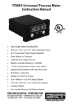
1
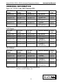
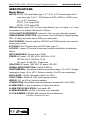
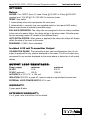
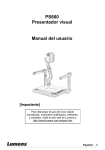
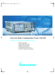
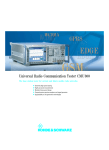
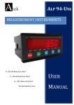
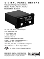
D I G I TA L PA N E L M E T E R S
Universal Temperature Meters
Model PD750, PD751, PD752
Instruction Manual
• J, K, T, E, R, and S Thermocouples
• 100 Ω Platinum RTD
• 10 Ω Copper RTD
• 120 Ω Nickel RTD
• Displays °F or °C
• Factory Calibrated for All Inputs
• Type T T/C and RTDs Displayed to 0.1°
• NEMA 4X, IP65 Front Panel
• 115 VAC, 230 VAC, or 24 VDC Power Options
• 2 or 4 Relays + 4-20 mA Output Option
¨
UL Listed (PD750 AC Powered Units Only)
PRECISION DIGITAL CORPORATION
19 Strathmore Road • Natick MA 01760 USA
Tel (800) 610-5239 • Fax (508) 655-8990
www.predig.com
Model PD750, PD751, PD752 Universal Temperature Meters
TABLE OF CONTENTS
Instruction Manual
SPECIFICATIONS . . . . . . . . . . . . . . . . . . . . . . . . . . . . . . . . . . . . . . . . . . . . . . . . . . .4
OPTIONS . . . . . . . . . . . . . . . . . . . . . . . . . . . . . . . . . . . . . . . . . . . . . . . . . . . . . . . . . .5
SETUP . . . . . . . . . . . . . . . . . . . . . . . . . . . . . . . . . . . . . . . . . . . . . . . . . . . . . . . . . . . .6
POWER and SIGNAL CONNECTIONS . . . . . . . . . . . . . . . . . . . . . . . . . . . . . . . . . . .6
PROGRAMMING . . . . . . . . . . . . . . . . . . . . . . . . . . . . . . . . . . . . . . . . . . . . . . . . . . . .8
CALIBRATION FLOW CHART . . . . . . . . . . . . . . . . . . . . . . . . . . . . . . . . . . . . . . . . . .9
CALIBRATION ([ALIb) . . . . . . . . . . . . . . . . . . . . . . . . . . . . . . . . . . . . . . . . . . . . . .10
INPUT TYPE (TYPE) . . . . . . . . . . . . . . . . . . . . . . . . . . . . . . . . . . . . . . . . . . . . . . . .11
SCALE (F or [) . . . . . . . . . . . . . . . . . . . . . . . . . . . . . . . . . . . . . . . . . . . . . . . . . . . .12
4 ALARM POINTS (Alars) . . . . . . . . . . . . . . . . . . . . . . . . . . . . . . . . . . . . . . . . . . .13
FAIL-SAFE OPERATION . . . . . . . . . . . . . . . . . . . . . . . . . . . . . . . . . . . . . . . . . . . . .15
RELAYS (Optional) . . . . . . . . . . . . . . . . . . . . . . . . . . . . . . . . . . . . . . . . . . . . . . . . . .16
SWITCHING INDUCTIVE LOADS . . . . . . . . . . . . . . . . . . . . . . . . . . . . . . . . . . . . . .17
ISOLATED 4-20 mA OUTPUT OPTION (OvtPvt) . . . . . . . . . . . . . . . . . . . . . . . . .18
LOCKOUT . . . . . . . . . . . . . . . . . . . . . . . . . . . . . . . . . . . . . . . . . . . . . . . . . . . . . . . .20
MOUNTING DIMENSIONS . . . . . . . . . . . . . . . . . . . . . . . . . . . . . . . . . . . . . . . . . . .20
OPTION CARD INSTALLATION . . . . . . . . . . . . . . . . . . . . . . . . . . . . . . . . . . . . . . .21
OTHER PRECISION DIGITAL PRODUCTS . . . . . . . . . . . . . . . . . . . . . . . . . . . . . .23
DEFINITIONS
TYPE, INPUT TYPE: To program unit for input type,(i.e. T/C or RTD).
F or [, Fahrenheit or Celsius: To program unit for Fahrenheit or Celsius display.
[ALIb, CALIBRATION: To re-calibrate unit using a calibrated signal source.
Alars, ALARM and RELAY POINTS: Sets alarm and relay set and reset points.
0vtPvt, 4-20 mA OUTPUT OPTION: Programs optional 4-20 mA output values.
Error, ERROR: Calibration not successful.
0PEN, OPEN T/C: Open thermocouple circuit indicated by flashing display.
!
WARNING
Hazardous voltages exist within enclosure.
Installation and service should be performed only by trained service personnel.
!
AVERTISSEMENT
Les pièces à l'intérieur du boîtier portent des tensions dangereuses. Seules
des personnes qualifiées et bien entrainées devraient entreprondre l'ótalonnage et
la maintenance.
Notice
The information contained in this document is subject to change without notice.
www.predig.com
2
Model PD750, PD751, PD752 Universal Temperature Meters
ORDERING INFORMATION
Instruction Manual
Type J, K, T, E, R, S, and 100 Ω Platinum RTD :
115 VAC
Model
PD750-3-N
PD750-3-14
PD750-3-15
PD750-3-16
230 VAC
Model
PD750-4-N
PD750-4-14
PD750-4-15
PD750-4-16
24 VDC
Model
PD750-2-N
PD750-2-14
PD750-2-15
PD750-2-16
PD750-3-17
PD750-3-18
PD750-4-17
PD750-4-18
PD750-2-17
PD750-2-18
115 VAC
Model
PD751-3-N
PD751-3-14
PD751-3-15
PD751-3-16
230 VAC
Model
PD751-4-N
PD751-4-14
PD751-4-15
PD751-4-16
24 VDC
Model
PD751-2-N
PD751-2-14
PD751-2-15
PD751-2-16
PD751-3-17
PD751-3-18
PD751-4-17
PD751-4-18
PD751-2-17
PD751-2-18
115 VAC
Model
PD752-3-N
PD752-3-14
PD752-3-15
PD752-3-16
230 VAC
Model
PD752-4-N
PD752-4-14
PD752-4-15
PD752-4-16
24 VDC
Model
PD752-2-N
PD752-2-14
PD752-2-15
PD752-2-16
PD752-3-17
PD752-3-18
PD752-4-17
PD752-4-18
PD752-2-17
PD752-2-18
Options Installed
No Options
2 Relays
4-20mA Out
2 Relays +
4-20 mA Out
4 Relays
4 Relays +
4-20 mA Out
Option
Card*
PD174
PD175
PD176
PD177
PD178
10 Ω Copper
Options Installed
No Options
2 Relays
4-20mA Out
2 Relays +
4-20 mA Out
4 Relays
4 Relays +
4-20 mA Out
Option
Card*
PD174
PD175
PD176
PD177
PD178
120 Ω Nickel
Options Installed
No Options
2 Relays
4-20mA Out
2 Relays +
4-20 mA Out
4 Relays
4 Relays +
4-20 mA Out
Option
Card*
PD174
PD175
PD176
PD177
PD178
Ordering example: PD750-3-14, temperature meter powered from
115 VAC (-3) with 2 relays (-14).
3
www.predig.com
Model PD750, PD751, PD752 Universal Temperature Meters
SPECIFICATIONS
Instruction Manual
Basic Meter
INPUTS: PD750: Field selectable: type J, K, T, E, R, or S Thermocouples with 1°
resolution; type T to 0.1° 100 Ω platinum RTD (.00385 or .00392 curve)
to 1° or 0.1° resolution.
PD751: 10 Ω copper RTD
PD752: 120 Ω nickel RTD
DISPLAY: Bright, large, 0.56” (14.2mm) high efficiency red, 41/2 digits. F or C may
be switched on to indicate Fahrenheit or Celsius.
COLD JUNCTION REFERENCE: Automatic, fixed, no user calibration needed.
SENSOR BREAK DETECTION: Open sensor circuit indicated by display flashing
0pen. All relays and alarm status LEDs go to alarm state.
HOLD READING: Connect switch to ACK/HLD and COM terminals, also connect
jumper pins on rear.
ACCURACY: See Thermocouple and RTD chart, page 11.
LOCKOUT: Jumper JP2 at rear of instrument restricts modification of calibration
values.
INPUT IMPEDANCE: Greater than 100 KΩ.
POWER: AC power: 115 VAC ±10%, 50/60 Hz, 10 VA.
230 VAC ±10%, 50/60 Hz, 10 VA.
DC power: 22-28 VDC, 6 watts max.
ISOLATION: AC power: 1500 VAC; DC power: 500 VDC.
NORMAL MODE REJECTION: 64 dB at 50/60 Hz
ENVIRONMENTAL: Operational ambient temperature range: 0 to +60°C. Storage
temperature range: -40 to +85°C. Relative humidity: 0 to 90% non-condensing.
ENCLOSURE: 1/8 DIN, high impact plastic, UL 94V-0.
FRONT PANEL: NEMA 4X, IP65, panel gasket provided.
WEIGHT: 19.7 oz (559 g) (including options)
CONNECTIONS: Removable screw terminal block, accepts #22 to #12 AWG.
ALARM POINTS: 4, any combination of high or low alarms.
ALARM STATUS INDICATION: Front panel LED
ALARM DEADBAND: 0-100% of full scale, user selectable.
UL FILE NUMBER: E160849; 508 Industrial Control Equipment
(PD750 AC Powered Unit only)
www.predig.com
4
Model PD750, PD751, PD752 Universal Temperature Meters
OPTIONS
Instruction Manual
Relays
RATING: 2 or 4 SPDT (form C); rated 2 Amp @ 30 VDC or 2 Amp @ 250 VAC
resistive load; 1/14 HP @ 125 / 250 VAC for inductive loads.
RESET: User select.
1. Automatically when the input passes the reset point.
2. Automatically + manually (via user supplied switch or front panel ACK button).
Manual reset resets all manually resetable relays.
FAIL-SAFE OPERATION: The relay coils are energized in the non-alarm condition.
In the case of a power failure, the relays will go to the alarm state. Fail-safe operation by removing jumper J2 located on the Options Board.
AUTO INITIALIZATION: When power is applied to the meter, the relays will always
reflect the state of the input to the meter.
DEADBAND: 0-100%, User selectable.
Isolated 4-20 mA Transmitter Output
CALIBRATION RANGE: The transmitter output can be calibrated so that a 4 mA
output is produced for any number displayed on the meter. The 20 mA output may
correspond to any number displayed on the meter above or below the 4 mA output
display.
OUTPUT LOOP RESISTANCE:
Power supply:
minimum
maximum
24 VDC
10 Ω
600 Ω
35 VDC (external)
600 Ω
1000 Ω
ACCURACY: ± 0.1% F.S., ± .004 mA.
ISOLATION: 500 VDC or peak AC, input-to-output or input/output-to-power line.
EXTERNAL LOOP POWER SUPPLY: 35 V max.
WARRANTY:
2 years parts & labor
EXTENDED WARRANTY:
1 or 2 years, refer to the Price List for details.
5
www.predig.com
Instruction Manual
Model PD750, PD751, PD752 Universal Temperature Meters
SETUP
Programming and installing the meter involves six basic
steps.
Step 1
Step 2
Remove jumper JP2 if installed, to disable the lockout feature.
Configure the input signal jumper JP1 according to the input
type, thermocouple or RTD, see charts below.
Connect the input signal according to the chart below.
Connect power.
Program the input type, choice 0-10, see page 11.
Program the scale type, Fahrenheit or Celsius, see page 12.
Step 3
Step 4
Step 5
Step 6
POWER and SIGNAL CONNECTIONS
24 V Transmitter
power: P+, P-
For DC powered units see diagrams on page 7
No Connection
RTD
A
AC
IN
MK C
A
S
C O
I
K
C
I
K
C
G
/
K
G
/
K
N
H O
N
H O
A
L
U
A
L
L
D T
L
D T
AC
L L P+P- C A E + Ð
JP2
O C X
JP1
/
H
H
L
L
Four-Wire RTD Connections
JP2
JP1
Three-Wire RTD Connections
T/C
RTD
A
S
I
M K C
U
D
D
L L P+P- C A E + Ð
O C X IN
IN
MK C
/
AC
L
C O
L L P+P- C A E + Ð
O C X
RTD
L
S
L
A
C O
K C
S
I
K
L
C O
C
K
K
G
/
N
H O
G
/
N
H O
A
L
U
A
L
L
D T
L
D T
AC
L L P+P- C A E + Ð
O C X IN
JP2
JP1
M K C
/
/
H
H
L
L
D
U
JP2
JP1
D
Two-Wire RTD Connections
Thermocouple Connections
6
Model PD750, PD751, PD752 Universal Temperature Meters
Instruction Manual
POWER and SIGNAL CONNECTIONS for
DC POWERED UNITS
No Connection
RTD
A
22-28 VDC
V-V+
C O
I
K
C
G
/
K
N
H O
IN
M K C
A
A
L
L
C
/
U
A
L
D T
L
D T
V-V+
JP2
C A E + Ð
O C X
JP1
IN
M K C
K
U
JP2
JP1
Three-Wire RTD Connections
T/C
A
22-28 VDC
IN
A
L
L
S
C O
S
C O
I
K
C
I
K
G
/
K
N
H O
A
L
L
C
G
/
N
H O
U
A
L
D T
L
D T
C A E + Ð
M K C
I
H O
RTD
O C X
C O
K
G
22-28 VDC
Four-Wire RTD Connections
V-V+
L
S
N
C A E + Ð
O C X
RTD
L
S
22-28 VDC
V-V+
JP2
C A E + Ð
O C X
JP1
M K C
Two-Wire RTD Connections
K
U
JP2
IN
JP1
Thermocouple Connections
WIRING INSTRUCTIONS
1. All field connections to be made with either solid or stranded insulated wire.
Strip length = 1/4" (7 mm). Tighten screw terminals to 4.5 lb-in (0.5 Nm).
Do not pre-treat wire with solder.
2. Terminals connected to line voltage (e.g. L, RELAY 1-4): Use AWG # 12-18 copper wire,
600 volt, 60°C or 60/75°C. Connect only one wire to each terminal.
3. Terminals not connected to line voltage (e.g. IN, EXC, ACK, COM, P+, P-, V+, V-, +, -):
Use AWG #12-22 wire. If using AWG #20 or smaller wire, up to two wires may be connected
to each terminal. If using AWG #18 or larger wire, only one wire may be connected to each
terminal.
7
www.predig.com
Model PD750, PD751, PD752 Universal Temperature Meters
PROGRAMMING
Instruction Manual
The meter’s Single Button Scaling feature allows it to be programmed using only the
ENTER button. The general procedure is to press the ENTER button to accept a
flashing display or to wait for the display to scroll and press ENTER when the
desired display appears.
For instance when the ENTER button is pressed, the meter scrolls through the standard programming routine titles: [ALIb , TYPE, F or [, Alars. It will also scroll the
optional programming routine title: OvtPvt if the meter contains the isolated 4-20
mA Output Option. To enter a programming routine, press ENTER when the meter
displays the desired programming routine title.
The following flow chart overviews the meter programming routines.
Display scrolls programming routines.
Press ENTER
Press ENTER to select desired routine.
Press
Press
Press
Press
Press
ENTER
ENTER
ENTER
ENTER
ENTER
2 point
Calibration
Set
Decimal
Point
Program
Alarms
(AL IB appears if E-(AL is selected
appears
if I-(AL isinstructions
selected
There are 5S(ALE
basic
programming
*
Program
Calibrate
Noise
4-20 mA
Filter
Output
** Only appears if 4-20 mA
output is installed
1. If the flashing display is OK, press ENTER before it stops flashing to accept it.
2. If the flashing display is not OK, (or if ENTER was not pressed in time to
accept it), wait for first digit to flash.
3. If a flashing digit is OK press ENTER before it starts to scroll to accept it.
4. If a flashing digit is not OK, (or if ENTER was not pressed in time to accept it),
wait for the digit to scroll, and press ENTER when OK.
5. Digits will scroll until ENTER is pressed. When a digit is accepted by pressing
ENTER, the next digit flashes.
For best results, allow the meter to warm up for at least
30 minutes before calibrating.
www.predig.com
8
Model PD750, PD751, PD752 Universal Temperature Meters
CALIBRATION FLOW CHART
Instruction Manual
The following flow chart illustrates a 2 point calibration using Single Button Scaling.
The same general procedure is used for alarm set and reset point programming and
4-20 mA output programming.
Press ENTER
Press ENTER when
appears
flashes
Apply
input 1 signal
(e.g. 2 V)
flashes
apply input 2
Press ENTER
(e.g. 20 V)
Is
entire flashing
YES
Press ENTER
display OK?
NO
Has
Wait for
input 2 been
digit to flash
NO
calibrated
yet?
YES
Wait for digit
to scroll
NO
Is
Calibration
the flashing
Complete!
digit OK?
YES
Press
ENTER when OK
Press ENTER
Is
entire display
NO
flashing?
YES
9
www.predig.com
Model PD750, PD751, PD752 Universal Temperature Meters
CALIBRATION ((ALIb)
Instruction Manual
The PD750 is pre-calibrated for 6 types of thermocouples and 2 types of 100 Ω RTD
sensors. The PD751 is pre-calibrated for 10 Ω copper RTD sensors and the PD752
is pre-calibrated for 120 Ω nickel RTD sensors.
These input ranges may be re-calibrated and should be checked every 12 months.
Calibration is performed from the front panel using the ENTER button. It does not
require any tools or disassembly of the meter. The only equipment needed is a thermocouple calibrator or a 5 decade resistance box with an accuracy of about 0.1%
and a minimum resistance of 0.01 Ω for RTDs.
Go to INPUT TYPE on page 11 if calibration is not necessary.
Input 1 Calibration
1. Press ENTER, when [ALIb appears press ENTER again.
2. Meter flashes iNPT1. Apply input 1 (low signal) using a calibrator, THEN press
ENTER.
3. All digits flash for 3 seconds.
If this is the desired display for input 1, press ENTER before
entire display stops flashing, (meter will then flash InPt 2). Go
to step 9 below.
If this is not the desired display, (or if ENTER was not pressed
in time to accept the display) wait for the first digit to flash.
First digit flashes for 3 seconds before it scrolls.
4. When digit is OK, press ENTER, next digit will flash for 3 seconds before it scrolls.
5. When flashing digit is OK, press ENTER, next digit will flash for 3 seconds before
it scrolls.
6. Repeat step 4 for each remaining digits.
7. When last digit is OK, press ENTER.
8. Entire display will flash for 3 seconds. Press ENTER within the 3 seconds if OK to
complete input 1 calibration. If not OK, wait for first digit to flash and go to step 3
above.
9. Meter flashes iNPT 2. Apply input 2 (high signal) using a calibrator, THEN press
ENTER.
10. GO TO STEP 3 ABOVE.
Calibration Error
An Error message during calibration indicates that the calibration process was not
successful. The meter should be recalibrated.
An Error message will appear if input 1 and input 2 signals are within 4 millivolts.
An Error message will appear if input 1 signal is inadvertently also applied for
input 2 calibration, or ENTER is pressed before applying input 2.
10
Model PD750, PD751, PD752 Universal Temperature Meters
INPUT TYPE (TYPE)
Instruction Manual
The meter must be programmed for the input type it is to accept. Selecting the
wrong input type will cause an incorrect temperature to be displayed.
Selecting Input Type
1. Press ENTER. When TYPE appears, press ENTER again.
2. The meter displays TYPE and starts to scroll through make it choice. Press
ENTER when desired digit appears, (see chart below). Meter will then reset back to
indication mode.
PD750 Input Ranges
Type Number
0
Type of Input
Type J T/C
1
Type K T/C
2
Type T T/C
3
4
Type T T/C
(0.1°)
Type E T/C
5
Type R T/C
6
Type S T/C
7
100 Ω RTD
(0.00385, 0.1°)
100 Ω RTD
(0.00392, 0.1°)
100 Ω RTD
(0.00385, 1°)
100 Ω RTD
(0.00392, 1°)
8
9
10
Range
-328° to 1382°F
-200° to 750°C
-328° to 2498°F
-200° to 1330°C
-330° to 760°F
-200° to 404°C
-330.0° to 760.0°F
-200.0° to 404.0°C
-328° to 1832°F
-200° to 1000°C
32° to 3213°F
0° to 1767°C
40° to 3214°F
4° to 1768°C
-328.0° to 1382.0°F
-200.0° to 750.0°C
-328.0° to 1382.0°F
-200.0° to 750.0°C
-328° to 1382°F
-200° to 750°C
-328° to 1382°F
-200° to 750°C
Accuracy
±2°F
±1°C
±2°F
±1°C
±2°F
±1°C
±2°F
±1°C
±2°F
±1°C
±5°F
±3°C
±6°F
±3°C
±0.7°F
±0.4°C
±0.7°F
±0.4°C
±1°F
±1°C
±1°F
±1°C
PD751 Input Ranges
Type Number
0
1
Type of Input/ Resolution
10 Ω Cu
0.1 degree
10 Ω Cu
1 degree
Range
-328.0° to 500.0°F
-200.0° to 260.0°C
-328° to 500°F
-200° to 260°C
Accuracy
±0.2°F
±0.1°C
±0.2°F
±0.1°C
Range
-112.0° to 608.0°F
-80.0° to 320.0°C
-112° to 608°F
-80° to 320°C
Accuracy
±0.2°F
±0.1°C
±0.2°F
±0.1°C
PD752 Input Ranges
Type Number
2
3
Type of Input/ Resolution
120 Ω Ni
0.1 degree
120 Ω Ni
1 degree
11
Instruction Manual
Model PD750, PD751, PD752 Universal Temperature Meters
RECOMMENDED CALIBRATION POINTS
Type
Number
Type of Input
Input 1
(Low)
Input 2
(High)
Check
(Middle)
0
Type J T/C
32°F
1182°F
600°F
1
Type K T/C
32°F
1183°F
960°F
2
Type T T/C
32°F
693°F
360°F
3
Type T T/C
32.0°F
693.0°F
360.0°F
4
Type E T/C
32°F
1652°F
840°F
5
Type R T/C
100°F
3000°F
1500°F
6
Type S T/C
100°F
3000°F
1500°F
7
100Ω RTD
(0.00385, 0.1°)
32.0°F
100Ω
1148.0°F
320.12Ω
590.0°F
215.61Ω
8
100Ω RTD
(0.00392, 0.1°)
32.0°F
100Ω
1127.0°F
320.89Ω
580.0°F
215.87Ω
9
100Ω RTD
(0.00385, 1°)
32°F
100Ω
1148°F
320.12Ω
590°F
215.61Ω
10
100Ω RTD
(0.00392, 1°)
32°F
100Ω
1127°F
320.89Ω
580°F
215.87Ω
SCALE (F or [)
F or C may be switched on to indicate Fahrenheit or Celsius.
Selecting Fahrenheit or Celsius
1. Press ENTER, when F or [ appears press ENTER again.
2. The meter will display F or [ alternately. Press ENTER when desired character is
flashing. Meter will then return to indication mode and display the temperature in
either Fahrenheit or Celsius.
www.predig.com
12
Model PD750, PD751, PD752 Universal Temperature Meters
4 ALARM POINTS (Alars)
Instruction Manual
The meter is equipped with 4 alarm points as a standard feature. Each alarm may
be programmed for either a high or low alarm and for 0-100% deadband. Front
panel LEDs indicate alarm status.
Options for 2 and 4 relays are available.
To program a high alarm, program the set point above the reset point. To program a
low alarm, program the set point below the reset point.
To program the alarm deadband, set the reset point above or below the set point by
an amount equal to the desired deadband value.
Example: Alarm 2 is a high alarm that trips at 1500° and has a deadband of 100°
Alarm 2 set point is set at 1500° and its reset point at 1400°
Alarm Set and Reset Point Programming (Alars)
Alarm set and reset point programming is performed in the Alars routine.
1. To enter the Alars routine, press ENTER and when Alars appears, press
ENTER again. This starts a scan of the 4 alarm set and reset points.
The scan sequence begins with a flashing display of alarm #1 set point. The “1”
LED and “S” LED are illuminated to indicate the meter is flashing alarm #1 set point
value.
2. All digits flash for 3 seconds.
If this is the desired display for this alarm point, press ENTER. Pressing
ENTER completes this alarm point programming. Proceed to step 8 for
next alarm point programming.
If this is not the desired display, wait for the first digit to flash. It will flash
for 3 seconds before it starts to scroll.
3. If the first flashing digit is OK, press ENTER before it starts to scroll to accept it,
the next digit flashes- go to step 6. If not OK, wait for first digit to scroll.
4. When the first digit is OK, press ENTER and the next digit flashes for 3 seconds
before it starts to scroll.
13
www.predig.com
Model PD750, PD751, PD752 Universal Temperature Meters
Instruction Manual
5. If the flashing digit is OK, press ENTER before it scrolls. If not OK, wait for digit to
scroll.
6. When digit is OK, press ENTER. Program remaining digits in same fashion.
7. When the last digit is OK, press ENTER. The entire display flashes for 3 seconds.
Press ENTER if OK to complete alarm point programming and proceed to step 8. If
not OK, wait, first digit flashes. Repeat steps 3-7.
8. When an alarm set or reset point has been programmed the scan moves to the
next alarm set or reset point. To program the remaining alarm set and reset points,
repeat steps 2-8.
Determine which alarm set or reset point is being programmed by noting which
LEDs are illuminated. For instance, if the “3” LED and the “R” LED are illuminated,
the meter is displaying alarm #3 reset point. When alarm programming is complete
the meter will display the process input signal and the front panel LEDs will indicate
alarm status.
Programming Confirmation
To verify that the alarm set and reset points have been programmed as desired,
press ENTER, and press ENTER again when Alars appears. Before the display
stops flashing #1 set point value, press ENTER again to advance the display to #1
reset point. Continue skipping through the remaining alarm set and reset points. To
alter an alarm point value, wait for the first digit to flash and follow steps 3-8 above.
Alarm Operation
When the meter detects an alarm, a front panel LED illuminates to indicate which
alarm point has been tripped. This LED will stay illuminated until the meter display
passes through the reset point.
Alarm Acknowledgment
The ACK button on the front panel resets the optional relays only and has no effect
on the alarm status LEDs.
www.predig.com
14
Instruction Manual
Model PD750, PD751, PD752 Universal Temperature Meters
FAIL-SAFE OPERATION:
J2
Front
Screw Terminals (Rear of PCB)
The relay coils are energized in the non-alarm condition. In the case of a power failure, the relays will go to the alarm state. The fail-safe operation can be disabled by
removing jumper J2 located at the front of the relay option card.
Relays
Ribbon Cable
OPTION CARD PIN-OUTS
Pin:
J1
J2
J3
Function:
1
Transmitter +
2
Transmitter -
1
Relay #1 Common
2
Relay #1 NC
3
Relay #1 NO
4
Relay #2 Common
5
Relay #2 NC
6
Relay #2 NO
1
Relay #3 Common
2
Relay #3 NC
3
Relay #3 NO
4
Relay #4 Common
5
Relay #4 NC
6
Relay #4 NO
PD175
PD176
PD174
PD178
PD177
Notes:
1. Alarm acknowledgement terminals (ACK and COM) are located on the meter main board.
2. In the alarm condition, the NC contact is connected to common in the fail-safe mode.
15
www.predig.com
Model PD750, PD751, PD752 Universal Temperature Meters
RELAYS (Optional)
Instruction Manual
The meter is available with 2 and 4 relays. The SPDT relays can be programmed
for automatic or automatic + manual reset. The relays can also be programmed for
0-100% deadband.
Set and Reset Point Programming
Refer to page 13 to program the alarm (relay) set and reset points.
Automatic and Manual Reset Programming
There are two ways to reset the relays:
1. Automatically when the signal passes through the reset point.
2. Automatically + manually via the front panel ACK button, or a user supplied
switch across terminals at the rear of the instrument. That is, a relay may be manually reset prior to the signal passing through the reset point, or, if it is not, it will automatically reset when the signal passes through the reset point.
A manual reset will reset all relays that are programmed for automatic + manual
reset.
An array of jumpers located behind the front panel on the Display Board is used to
program each relay for either automatic or automatic + manual reset. Refer to page
21 for front panel removal instructions. The top jumper is used for relay 1, the next
for relay 2, etc. A relay will automatically reset if no jumper is installed. A relay will
automatically reset, plus can be manually reset, if a jumper is installed over its
respective pins.
1
2
3
4
Jumpers to program relays for either automatic or automatic + manual reset.
Example: Relay 1 is programmed for automatic reset only.
Relays 2, 3, and 4 are programmed for automatic + manual reset.
www.predig.com
16
Model PD750, PD751, PD752 Universal Temperature Meters
SWITCHING INDUCTIVE LOADS
Instruction Manual
The meter has the ability to suppress electrical noise generated by switching inductive loads. However, installing suppressors improves this performance even more
and prolongs the life of the meter’s relay contacts.
This suppression can be obtained with RC networks assembled by the user or purchased as a complete assembly. Refer to the following circuits for RC network
assembly and installation:
AC and DC LOADS
1
L
O
A
D
2
3
Choose R and C as follows
R: 0.5 to 1 Ω for each volt across the contacts
C: 0.5 to 1 µF for each 1 A through closed contacts
Notes
1. Use capacitors rated for 240 VAC.
2. Snubbers may affect load release time of solenoid loads, check to confirm proper operation.
3. Install the RC network right at the meter’s relay screw terminals. An RC network may also be
installed across the load.
LOW VOLTAGE DC LOADS
1
L
O
A
D
2
3
Use a diode with a reverse breakdown voltage two to three times the circuit voltage
and forward current at least as large as the load current.
RC NETWORKS
Suppressors are available and should be applied to each relay that switches an
inductive load. Part number PDX6901.
17
www.predig.com
Model PD750, PD751, PD752 Universal Temperature Meters
Instruction Manual
ISOLATED 4-20 mA OUTPUT OPTION (OvtPvt)
The meter can be equipped with an isolated 4-20 mA output signal option that can
be programmed to produce a 4-20 mA output for virtually any input.
Connections
The following drawings illustrate the 4-20 mA output signal being powered from the
meter’s internal 24 V power supply (AC powered units only) and by an external
power supply.
- +
Signal
Input
-
Meter, Recorder
Controller, etc.
+
- +
E A
C P- P+ L
L
4-20 mA output signal being powered by meter’s internal 24 V power supply.
AC powered units only
+
- +
Signal
Input
-
Loop
Power Supply
- +
Meter, Recorder
Controller, etc.
E A
C P- P+ L
L
+
4-20 mA output signal being powered from an external 24 V power supply.
!
If the output loop is powered by an external supply, the loop power supply
must be turned on before the meter is turned on. Otherwise, the output loop signal
may be incorrect.
Calibration
The isolated 4-20 mA output signal is calibrated using the front panel ENTER button
and uses the same Single Button Scaling technique that is used to calibrate the signal input and the alarm set and reset points. A multimeter may be connected to the
output terminals to verify calibration, but it is not required as part of the calibration
process.
www.predig.com
18
Model PD750, PD751, PD752 Universal Temperature Meters
4 mA Output Calibration
Instruction Manual
1. Press ENTER, when OvtPvt appears press ENTER again.
2. All digits flash for 3 seconds, a green LED labeled “4” illuminates indicating the
flashing display is the value at which the meter will produce a 4 mA output.
If this is the desired display at which the meter will produce a 4 mA out
put, press ENTER before entire display stops flashing. The meter indicates that the 4 mA Output Calibration is now complete by illuminating
the green “20” LED. Go to 20 mA Output Calibration below.
If this is not the desired display, (or if ENTER was not pressed in time to
accept the display) wait for the first digit to flash.
3. First digit flashes for 3 seconds before it scrolls.
4. When first digit is OK, press ENTER, next digit will flash for 3 seconds before it
scrolls.
5. When flashing digit is OK, press ENTER, next digit will flash for 3 seconds before
it scrolls.
6. Repeat step 5 for each remaining digits.
7. When last digit is OK, press ENTER.
8. Entire display will flash for 3 seconds. Press ENTER within the 3 seconds if OK to
complete 4 mA Output Calibration. If NOT OK, wait for first digit to flash and go to
step 5 above.
20 mA Output Calibration
Note: The 20 mA output calibrates in the same fashion as 4 mA output so the 4 mA
Calibration Instructions will be referenced for most of the 20 mA Calibration
Instructions.
1. When ENTER is pressed to complete the calibration for 4 mA output, the green
LED labeled “20” illuminates indicating the flashing display is the value at which the
meter will produce a 20 mA output.
2. Repeat steps 2-8 in 4 mA Output Calibration above.
3. Upon acceptance of the display corresponding to the 20 mA output, the meter
exits the outPut routine and returns to indication mode.
19
www.predig.com
Model PD750, PD751, PD752 Universal Temperature Meters
Programming Confirmation
Instruction Manual
The values that have been programmed to produce the 4 and 20 mA outputs can be
quickly checked to make sure they are the desired values. To do this, enter the
OvtPvt routine by pressing ENTER and then pressing ENTER again when
OvtPvt appears.
The green “4” LED illuminates indicating the meter is displaying the value at which it
will produce a 4 mA output. Confirm that this is the desired value. Press ENTER
(within 3 seconds) before the entire display stops flashing and the green “20” LED
illuminates indicating the meter is displaying the value at which it will produce a 20
mA output. Confirm that this is the desired value. Press ENTER (within 3 seconds)
before the entire display stops flashing and the meter returns to indication mode.
LOCKOUT
Install jumper JP2 at rear of instrument to restrict modification of calibration values.
When ENTER is pressed with lockout jumper in place, only Alars and OvtPvt
routines are displayed. These routines may be entered to view their settings, but the
settings may not be altered.
www.predig.com
20
Model PD750, PD751, PD752 Universal Temperature Meters
Instruction Manual
OPTIONS CARD REMOVAL & INSTALLATION
Meter options are installed at the factory. To disable relays’ fail-safe operation, it is
necessary to remove the Boards from the case. Refer to the following instructions
and illustrations.
Disconnect power prior to performing
the following operations.
The meter's snap-off cover is held in place by 6 latches that snap into notches on
the snap-off cover. To remove the snap-off cover from the meter, grasp it firmly on
its top and bottom edges and pull it forward. The latch plate remains around the
meter's case.
To remove the circuit boards from the case:
1. Unscrew the retaining screws holding the circuit boards to the case.
2. Remove the screw terminal connectors at the rear of the meter.
3. Push the boards through the case by applying pressure to the circuit boards at
the rear of the meter. Apply pressure evenly to both boards.
4. Do not apply pressure to the vertical display board.
Latch
Latch Plate
Retaining Screws and Washers
Snap-off Cover
Front Cover Removal
Notch
5. Configure fail-safe jumper on Options Board as required. Remove J2 jumper to
disable fail-safe operation.
6. To avoid electric shock, re-install the circuit boards in the case prior to applying
power.
All programming and calibrating can be performed
with the circuit boards installed in the case.
21
Instruction Manual
Model PD750, PD751, PD752 Universal Temperature Meters
To re-install the meter in its case:
1. Fold the Options Board over the Main Board, grasp both boards so the Main
Board is on the bottom and the two Boards are separated by about an inch.
2. Insert the two boards together into the case. Be sure both the top and bottom
boards engage the rails, which hold them in place.
3. Do not press on the Display Board when seating the assembly in the case.
4. Install washers and retaining screws in 4 corners of meter and install front cover.
Input Configuration
Jumpers
Screw Terminals (Rear of PCB)
Relays
Transformer
Ribbon Cable
J2
Front
Option Card Installation
Display PCB
MOUNTING DIMENSIONS
FRONT VIEW
SIDE VIEW
4.25" (108mm)
Panel Thickness Ð
.125"-.250" (3.17mm-6.34mm)
2.30"
(59mm)
4.30" (109mm) Installed
4.83" (123mm) Req'd for Inst.
.575"
(14.6mm)
6" (152mm) Clearance
Mounting Dimensions
Notes:
1. Panel cutout required: 1.772" X 3.622" (45 mm x 92 mm) 1/8 DIN
2. Panel thickness: 0.125" - 0.250" (3.17 mm - 6.34 mm)
3. Clearance: allow 6 inches (152 mm) behind the panel
22
Model PD750, PD751, PD752 Universal Temperature Meters
Other Precision Digital Products
MODEL
PD118
PD141AFO
PD202-253
PD602
PD644
PD650
PD655
PD656
PD660
PD661
PD673
PD675
PD677
PD685
PD686
PD687
PD690
PD691
PD692
PD693
PD696
PD697
PD698
PD740
PD751-752
PD755
PD756
PD757
PD765
PD865
PD940-981
Instruction Manual
DESCRIPTION
MINIMUX® 8 Point Scanner
VIGILANTE® four Point Annunciator with First-Out
Digital Pressure Gauges
Dart Low-Cost 1/8 DIN Process Meter
Javelin D High-Voltage DC Panel Meter
2.3" LED NEMA 4X Large Display Process Meter
1.0" LED NEMA 4X Large Display Process Meter
0.8" LED Exp-Proof Large Display Process Meter
Low-Cost NEMA 4X Loop Powered Meter
Low-Cost Exp-Proof Loop Powered Meter (FM & CSA)
41/2 Digit Loop Powered 1/8 DIN Meter
41/2 Digit Loop Powered NEMA 4X Meter (FM & CSA)
41/2 Digit Loop Powered Exp-Proof Meter
31/2 Digit Loop Powered NEMA 4X Meter (GeneralPurpose)
31/2 Digit Loop Powered NEMA 4X Meter (FM & CSA)
31/2 Digit Loop Powered Exp-Proof Meter (FM & CSA)
1/8 DIN Analog Input Process Meter (UL Listed)
1/8 DIN Strain Gauge & mV Input Meter (UL Listed)
1/8 DIN Analog Input Flow Rate/Totalizer (UL Listed)
1/8 DIN Pulse Input Flow Rate/Totalizer (UL Listed)
1/8 DIN Loop Powered Flow Rate/Totalizer
NEMA 4X Loop Powered Flow Rate/Totalizer
Exp-Proof Loop Powered Flow Rate/Totalizer (FM & CSA)
Javelin T TC & RTD Temperature Meter (Low-Cost)
10 Ω Cu & 120 Ω Ni RTD Temperature Meters (UL Listed)
1.0" LED NEMA 4X Large Display Temperature Meter
0.8" LED Exp-Proof Large Display Temperature Meter
2.3" LED NEMA 4X Large Display Temperature Meter
Trident Process & Temperature Meter (UL Listed)
Snooper Modbus Serial Input Meter
ConsoliDator® Multi-Channel Controllers
23
Model PD750, PD751, PD752 Universal Temperature Meters
Instruction Manual
How to Contact Precision Digital
• For Technical Support please
call: (800) 610-5239 or (508) 655-7300
fax: (508) 655-8990
e-mail: [email protected]
• For Sales Support or to place an order please
call: (800) 343-1001 or (508) 655-7300
fax: (508) 655-8990
e-mail: [email protected]
• For Extended Warranty, Setup & Calibration
Services please visit
www.predig.com
• For an online version of this instruction manual
please visit
www.predig.com
PRECISION DIGITAL CORPORATION
19 Strathmore Road • Natick MA 01760 USA
Tel (800) 610-5239 • Fax (508) 655-8990
LIM750 Rev E
11/05