1
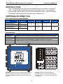
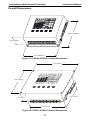
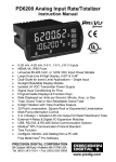
ConsoliDator™
Multi-Channel Controller
Instruction Manual
ConsoliDator 8 Features
ConsoliDator 4 Features
•
•
•
•
•
•
Eight 4-20 mA Inputs
Eight 24 VDC @ 20 mA
Two 4-20 mA Outputs
Four 4-20 mA Inputs
Four 24 VDC @ 20 mA
Four 4-20 mA Outputs
Common Features & Advantages
•
•
•
•
•
•
•
•
Nine 10 A Relays
Four Pulse Inputs
Four Digital Inputs
90-264 VAC and 8-30 VDC Powered
®
RS-232 Modbus RTU Serial Communication
Full Graphical 4.75" x 3.5" LCD with Backlight
Intuitive Menus in English
All Inputs & Outputs Factory Calibrated
PRECISION DIGITAL CORPORATION
19 Strathmore Road • Natick MA 01760 USA
Tel (800) 343-1001 • Fax (508) 655-8990
www.predig.com
ConsoliDator Multi-Channel Controller
Visit our Web Site
http://www.predig.com/
2
Instruction Manual
ConsoliDator Multi-Channel Controller
Instruction Manual
INTRODUCTION
The ConsoliDator is an easy to use multiple-channel controller. It accepts
4-20 mA inputs, flow meter pulse inputs, and digital inputs. It is equipped
with multiple relays, which all have user-definable actions, 4-20 mA outputs,
and Modbus protocol serial communication capabilities.
ORDERING INFORMATION
4-20 mA & Pulse Input Models
Model
Mounting
PD980-8K9-15
PD981-8K9-15
PD940-8K9-15
PD941-8K9-15
Wall
Panel
Wall
Panel
4-20
Inputs
Pulse
Inputs
4-20
Outputs
Relays
8
4
2
9
4
4
4
9
Accessories
Model
Description
PDA2901
PDP2901
PDP2902
PDA6901
PDX6901
NEMA 4X (UL Type 4X) Enclosure for PD981 or PD941 models.
Sub Panel with Terminal Strips for PDA2901 Enclosure.
Low-Cost Sub Panel without Terminal Strips for PDA2901.
2" Pipe Mounting Kit for PDA2901 Enclosure.
Snubber .01µF, 470Ω, Flexible Leads.
J1
INPUT
+ INPUT 2
+ INPUT 1
LOOP OUT
LOOP IN
G
+ INPUT 3
+ INPUT 4
KEY 1
KEY 2
KEY 3
KEY 4
COMMON
KEY 5
G
DIGITAL INPUTS
EXTERNAL KEYPAD
J2
OUTPUT
+24
ANALOG
OUTPUT 3
GND
LOOP IN
ANALOG
OUTPUT 2
LOOP OUT
LOOP OUT
COMMON
INTERNAL
POWER
LOOP IN
+24
GND
LOOP IN
LOOP OUT
ANALOG
OUTPUT 1
COMMON
INTERNAL
POWER
ANALOG
OUTPUT 4
J3
INPUT
GND/
RET
-
+
GND/
RET
GND/
RET
-
+
GND/
RET
ANALOG 1
GND/
RET
-
+
GND/
RET
ANALOG 7/
FLOW 3
-
+
ANALOG 8/
FLOW 4
-
+
GND/
RET
ANALOG 2
-
+
GND/
RET
ANALOG 3
-
+
ANALOG 4
J5
RELAY
J8
RELAY
NO
C
NO
NC
C
NC
NO
RELAY 5
RELAY 9
J7
POWER
C
NC
NO
RELAY 6
C
NC
NO
RELAY 7
C
NC
RELAY 8
J6
RELAY
GND
+
DC POWER
3
+
J4
INPUT
Model: PDP2901
Sub Panel for PDA2901 Enc
PDA2901 optional enclosure features quick-release
latches, a hinged front panel and internal space for
mounting additional components such as relays and
switches.
-
ANALOG 6/
FLOW 2
ANALOG 5/
FLOW 1
GND
N
AC POWER
H
NO
C
RELAY 1
NC
NO
C
RELAY 2
NC
NO
C
RELAY 3
NC
NO
C
NC
RELAY 4
PDP2901 optional sub panel features
terminal strips for convenient installation of
all power, analog, and relay lines using up to
8 AWG wire.
ConsoliDator Multi-Channel Controller
Instruction Manual
TABLE OF CONTENTS
INTRODUCTION ----------------------------------------------------------------------- 3
ORDERING INFORMATION -------------------------------------------------------- 3
TABLE OF CONTENTS-------------------------------------------------------------- 4
SPECIFICATIONS--------------------------------------------------------------------- 7
General------------------------------------------------------------------------------------------- 7
4-20 mA Analog Inputs --------------------------------------------------------------------- 8
Flow Meter Pulse Inputs-------------------------------------------------------------------- 8
Digital Inputs ----------------------------------------------------------------------------------- 8
Relays -------------------------------------------------------------------------------------------- 9
4-20 mA Transmitter Outputs----------------------------------------------------------- 10
Modbus® Serial Communications----------------------------------------------------- 10
Compliance Information------------------------------------------------------------------ 10
SAFETY INFORMATION ---------------------------------------------------------- 11
INSTALLATION ---------------------------------------------------------------------- 12
Unpacking------------------------------------------------------------------------------------- 12
Wall Mounting ------------------------------------------------------------------------------- 12
Panel Mounting------------------------------------------------------------------------------ 13
Connections---------------------------------------------------------------------------------- 14
Power Connections ---------------------------------------------------------------------- 14
Input Signal Connections --------------------------------------------------------------- 15
4-20 mA Analog Input Connections ---------------------------------------------- 15
Flow Meter Pulse Input Connections--------------------------------------------- 16
Digital Input Connections ----------------------------------------------------------- 16
Analog Output Connections------------------------------------------------------------ 17
Relay Connections ----------------------------------------------------------------------- 18
Switching Inductive Loads ---------------------------------------------------------- 18
RC Networks Available from Precision Digital --------------------------------- 18
Serial Communication Connections ------------------------------------------------- 19
External Keypad Connections --------------------------------------------------------- 19
NAVIGATING AND EDITING ----------------------------------------------------- 20
Soft-Keys and Buttons-------------------------------------------------------------------- 20
SETUP AND PROGRAMMING -------------------------------------------------- 21
Main Setup Menu --------------------------------------------------------------------------- 22
General Functions ------------------------------------------------------------------------ 22
Buzzer Settings------------------------------------------------------------------------ 22
Password Settings -------------------------------------------------------------------- 22
Backlight Settings --------------------------------------------------------------------- 23
Modbus Settings ---------------------------------------------------------------------- 23
Contrast Settings---------------------------------------------------------------------- 23
Configuring 4-20 mA Inputs------------------------------------------------------------- 24
Analog Input Display Preferences ------------------------------------------------ 24
Scaling the 4-20 mA Input ---------------------------------------------------------- 25
Setting Flow Meter Pulse Inputs------------------------------------------------------- 26
Flow Meter Pulse Input Display Preferences ---------------------------------- 27
Flow Meter Pulse Input Configuration ------------------------------------------- 27
4
ConsoliDator Multi-Channel Controller
Instruction Manual
Programming Relays ---------------------------------------------------------------------- 28
Supervisory or Summary Alarm Modes --------------------------------------------- 28
High or Low Alarm Modes -------------------------------------------------------------- 29
High or Low Pulse Alarm Modes ----------------------------------------------------- 30
Trigger Alarm Mode ---------------------------------------------------------------------- 32
Annunciator High or Low Alarm Modes --------------------------------------------- 33
Plunger Lift by Differential Pressure Mode----------------------------------------- 34
Plunger Lift by Time Mode ------------------------------------------------------------- 35
Lead-Lag Modes (Pump Alternation Control) ------------------------------------- 36
Lead-Lag Override Function ------------------------------------------------------- 37
Linear Pulse Width Modulation Mode ----------------------------------------------- 38
Proportional Plus Integral Pulse Width Modulation Mode ---------------------- 40
Setting 4-20 mA Outputs ----------------------------------------------------------------- 41
Linear Scaling of 4-20 mA Output ---------------------------------------------------- 41
PID Control Using 4-20 mA Output -------------------------------------------------- 42
OPERATION -------------------------------------------------------------------------- 43
Multiple Channel Operation Screen -------------------------------------------------- 43
Single Analog Input Operation Screen ---------------------------------------------- 44
Single Flow Meter Pulse Input Operation Screen-------------------------------- 45
Digital Input Operation Screen--------------------------------------------------------- 46
Manual Relay Control --------------------------------------------------------------------- 47
MODBUS® SERIAL COMMUNICATION--------------------------------------- 48
Modbus Register Tables ---------------------------------------------------------------- 49
TROUBLESHOOTING TIPS ------------------------------------------------------ 54
OTHER PRECISION DIGITAL PRODUCTS ---------------------------------- 55
Table of Figures
Figure 1. Wall Mount Dimensions (PD980 & PD940) ..................................... 12
Figure 2. Panel Mount Dimensions (PD981 & PD941) ................................... 13
Figure 3. Power Connections .......................................................................... 14
Figure 4. Transmitter Powered by Ext. Supply or Self-Powered .................. 15
Figure 5. Transmitters Powered by ConsoliDator ......................................... 15
Figure 6. Transmitters Powered by ConsoliDator ......................................... 15
Figure 6. Flow Meter Pulse Input Connections.............................................. 16
Figure 7. Digital Input From Switch Closure .................................................. 16
Figure 8. Digital Input From Live Signal ......................................................... 16
Figure 9. 4-20 mA Output Powered by ConsoliDator .................................... 17
Figure 10. 4-20 mA Output Powered by External Supply.............................. 17
Figure 11. Relay Connections ......................................................................... 18
Figure 12. AC and DC Loads Protection......................................................... 18
Figure 13. Low Voltage DC Loads Protection ................................................ 18
Figure 14. Serial Connections ......................................................................... 19
Figure 15. External Keypad Connections....................................................... 19
Figure 16. Pulse Relay Timing Diagram ......................................................... 31
Figure 17. Linear PWM Relay Timing Example .............................................. 39
Figure 18. PD980 & PD940 Overall Dimensions............................................. 53
Figure 19. PD981 & PD941 Overall Dimensions............................................. 53
5
ConsoliDator Multi-Channel Controller
Instruction Manual
Disclaimer
The information contained in this document is subject to change without notice.
Precision Digital Corporation makes no representations or warranties with
respect to the contents hereof, and specifically disclaims any implied warranties
of merchantability or fitness for a particular purpose.
All trademarks mentioned in this document are the property of their respective
owners.
6
ConsoliDator Multi-Channel Controller
Instruction Manual
SPECIFICATIONS
Except where noted all specifications apply to operation at +25°C (77°F).
General
DISPLAY
Graphical: 4.75" x 3.5" (121 mm x 89 mm) LCD with backlight
320 X 240 pixels; Numerical: ±999999
DISPLAY UPDATE
CALIBRATION
PASSWORD
2 seconds (0.5 Hz)
All ranges are calibrated at the factory.
Programmable password restricts modification of programmed
settings and use of manual control functions.
All programmed settings are stored in non-volatile memory for a
minimum of ten years if power is lost.
AC: 90-264 VAC, 47 to 63 Hz, 20 VA
DC: 8-30 VDC, 15 W
AC: Unit is protected internally. 5 A max, slow blow, 250 V min UL
Recognized external fuse recommended.
DC: 5 A max, slow blow, 250 V (or 50 V min) UL Recognized
external fuse recommended.
AC power is isolated from all inputs, outputs and relays to 1500 VAC.
Isolation to 5000 VAC between analog inputs and analog outputs
requires powering analog outputs with external supply.
Signal and output power grounds are connected to earth (chassis)
ground.
Operating temperature range: 0 to 50°C (32 to 122°F)
Storage temperature range: -40 to 60°C (-40 to 140°F)
Relative humidity: 0 to 90% non-condensing
*All functions operate down to -10°C (14°F). LCD response is slower
below 0°C (32°F) and may need contrast adjustment to be readable.
Removable screw terminal blocks accept 12 to 24 AWG wire.
DB9 male for serial connection.
Screw terminal connectors: 4.5 lb-in (0.5 Nm)
NON-VOLATILE
MEMORY
POWER
FUSE
ISOLATION &
GROUNDING
ENVIRONMENTAL
CONNECTIONS
TIGHTENING
TORQUE
ENCLOSURE
MOUNTING
WEIGHT
Type 1; Powder-coated steel; Color: warm gray
Wall Mount (PD980 & PD940): four screws/bolts
Panel Mount (PD981 & PD941): four screws/bolts
Cutout: 7.37" x 8.35" (187 mm x 212 mm)
Wall Mount
8.75" x 8.00" x 3.00" (222 mm x 203 mm x 76 mm)
(H x W x D)
Panel Mount
8.66" x 9.36" x 3.10" (220 mm x 238 mm x 79 mm)
(H x W x D)
5.5 lb (2.5 kg)
WARRANTY
EXTENDED
WARRANTY
1 year parts and labor
Warranty may be extended 1 year or 2 years. Contact factory for
pricing and details.
OVERALL
DIMENSIONS
7
ConsoliDator Multi-Channel Controller
Instruction Manual
4-20 mA Analog Inputs
ACCURACY
±0.03% of span ±1 count
TEMPERATURE DRIFT
50 PPM/°C from 0 to 50°C ambient
User selectable from zero to six places with automatic
overflow.
4-20 mA, Minimum span of 1 mA
DECIMAL POINT
INPUT RANGE
INPUT IMPEDANCE
NORMAL MODE
REJECTION
TRANSMITTER POWER
SUPPLY
ENGINEERING UNITS
130 Ω, current limited
Greater than 100 dB at 50/60 Hz.
Each input is equipped with +24 VDC current limited.
External supply may be substituted.
User selectable units or custom-entered units.
Flow Meter Pulse Inputs
SIGNAL RANGE
CONVERSION FACTOR
DISPLAY OPTIONS
ENGINEERING UNITS
RATE & TOTAL
DECIMAL POINT
TOTALIZER
TOTALIZER RESET
100 mVp-p to 15 Vp-p; 1 Hz to 10 kHz
Programmable from 0.00001 to 999999
Rate and total values displayed on screen.
Bargraphs user selectable to indicate either total or rate.
Show Total/Rate combinations as GAL & GPS, GAL &
GPM, GAL & GPH, GAL & GPD, MG & MGD, BBL & BPH,
BBL & BPD, LTR & LPD, LTR & LPH, LTR & LPS, CF &
CFS, CF & CFM, CF & CFH, CF & CFD, MCF & MCD.
Independent and user selectable from zero to six places
with automatic overflow.
Calculates total based on rate. Reading stored in nonvolatile memory every 5 minutes for power-loss recovery.
Via front panel buttons (Password restricted).
Digital Inputs
INPUT TYPES
Normally open switch: External excitation not required.
Open collector transistor: Open circuit voltage = 3 VDC
Closed Circuit Current = 18.5 mA
Switch closure or logic LO to terminals interpreted as "ON"
LO = 0 to 1 VDC, HI = 2.5 to 12 VDC
INPUT IMPEDANCE
240 Ω
Minimum input pulse (closed contact or LO) duration: 1 sec
Maximum input pulse frequency: 30 cycles per minute
SIGNAL REQUIREMENTS
8
ConsoliDator Multi-Channel Controller
Instruction Manual
Relays
RATING
SPDT (form C); rated 10 A @ 120/240 VAC or 5 A @ 28 VDC
resistive load; 1/3 HP @ 120/240 VAC for inductive loads.
Minimum load: 50 mA for AC, 10 mA @ 5 VDC
ISOLATION
1500 VAC between coil and contacts
DEADBAND
0-100% of full scale, user selectable
ELECTRICAL NOISE
SUPPRESSION
An external suppressor (snubber) should be connected to
each relay contact switching inductive loads, to prevent
disruption to the microprocessor’s operation.
Recommended suppressor value: 0.01 µF/470 Ω, 250 VAC
(Order: PDX6901).
ASSIGNMENT &
OPERATION
Any relay may be assigned to any analog or flow meter pulse
input channel. Multiple relays may be assigned to the same
channel. All relays are programmed independently.
High or Low Alarm: Assign to analog or pulse channel for
on/off relay control.
Annunciator High or Low: Assign to analog or pulse channel
for on/off relay control with reset capability from digital input
switch.
Summary Alarm: Use for indication of any relay entering alarm
state.
Supervisory Alarm: Use to indicate CPU failure or analog input
signal loss.
High or Low Pulse Action: Assign to analog or pulse input
channel for pulsing on/off timed relay control. Programmable
pulse width and delay.
Trigger: Assign to pulse channel for indication of user-defined
total increment. Programmable for scaled pulse output.
Plunger Lift: Assign to analog and/or pulse channels to control
a plunger lift system.
Lead-Lag Alternation (Sequence): Link multiple relays for
sequential operation. (Up to 9 relays). Programmable override
set points to turn on up to 5 relays.
Pulse Width Modulation: Assign to analog or pulse channel for
on/off signal modulated based on input. User selectable cycle
time.
PI Control: Assign to analog or pulse channel for Proportional
plus Integral on/off modulated duty cycle. Manual tuning
required.
MANUAL OVERRIDE
Override any relay (Password restricted). Relays do not
respond to input in this mode.
ACKNOWLEDGE
Front panel ACK key resets relays in Supervisory, Summary
and Annunciator Alarm Modes.
TIME DELAY
Programmable on/off delays, 0-999.9 sec, independent for
each relay
AUTO
INITIALIZATION
When power is applied to the controller, relays will reflect the
state of the input to the controller.
9
ConsoliDator Multi-Channel Controller
Instruction Manual
4-20 mA Transmitter Outputs
OUTPUT RANGE
CALIBRATION
SCALING RANGE
ASSIGNMENT &
OPERATION
ACCURACY
4.00 to 20.00 mA
Factory calibrated for 4-20 mA
Any process range.
Assign to any analog or pulse input channel for linear
scaling or for manually tuned PID control output.
TEMPERATURE DRIFT
50 PPM/°C from 0 to 50°C ambient. Output & Input drifts are separate.
Self powered or externally powered by 12 to 32 VDC
±0.05% F.S. ±0.01 mA
OUTPUT LOOP POWER
OUTPUT LOOP
RESISTANCE
Powered by controller: 10 to 600 Ω
Powered by external 12 VDC: 10 to 300 Ω
Powered by external 24 VDC: 10 to 600 Ω
Powered by external 32 VDC: 10 to 900 Ω
Modbus® Serial Communications
TYPE
RS-232 Modbus RTU
DEVICE ADDRESS
Programmable between 1 and 247
TRANSMIT
TIME DELAY
Programmable between 0 and 300 ms
BAUD RATE
Programmable from 1200 to 38400
DATA
8 bit (1 start bit, 1 stop bit)
PARITY
EVEN or NONE. (NONE parity uses 2 stop bits).
Compliance Information
UL LISTED
USA and Canada
UL 508 Industrial Control Equipment
UL FILE NUMBER
E160849
10
ConsoliDator Multi-Channel Controller
Instruction Manual
SAFETY INFORMATION
!
CAUTION: Read complete
instructions prior to
installation and operation of
the controller.
WARNING: Risk of
electric shock.
WARNING
Hazardous voltages present. Installation and service should be performed
only by trained service personnel.
11
ConsoliDator Multi-Channel Controller
Instruction Manual
INSTALLATION
Unpacking
Remove the instrument from its box. Inspect the packaging and contents for
damage. Report any damages to the carrier. If any part is missing or the
controller malfunctions, please contact your supplier or the factory for
assistance.
Wall Mounting
(For PD980 & PD940 Models)
•
Obtain four #10 screws and nuts.
•
Prepare four 1/4" holes through mounting surface spaced as shown.
•
Allow at least two inches of free space on all sides so that the removable
screw terminals and DB9 connector may be accessed for wiring.
•
Secure instrument to surface.
Dia. 0.25" (6.3 mm) 4 places
8.00" (203 mm)
7.25" (184mm)
Figure 1. Wall Mount Dimensions (PD980 & PD940)
12
ConsoliDator Multi-Channel Controller
Instruction Manual
Panel Mounting
(For PD981 & PD941 Models)
•
Obtain four #8 screws (M4.2) and nuts.
•
Obtain four washers with at least 5/16" O.D. If the device will be subjected to
vibration, lock washers are necessary.
•
Prepare four 1/4" (6.3 mm) clearance holes through mounting surface
spaced as shown.
•
Prepare panel cutout.
•
7.37" H x 8.35" W (187 mm x 212 mm)
•
Center cutout vertically and horizontally with respect to holes.
•
Maximum allowable inner radii: 0.1" (2.5 mm).
•
Remove all connectors.
•
Insert controller and secure to surface.
4 CLEARANCE HOLES:
Dia. 0.25" (6.3 mm)
PANEL
8.16" (207 mm)
CUTOUT
8.86" (225 mm)
Figure 2. Panel Mount Dimensions (PD981 & PD941)
13
ConsoliDator Multi-Channel Controller
Instruction Manual
Connections
Connections are made to removable screw terminal connectors and a DB9 male
serial connector. They are located around the sides of the controller.
!
Use copper wire with 60°C or 60/75°C insulation
for all line voltage connections. Observe all safety
regulations. Electrical wiring should be performed
in accordance with all applicable national, state,
and local codes to prevent damage to the
instrument and ensure personnel safety.
Power Connections
Power connections are made to one of the power terminal connectors. All units
are capable of being powered either by AC or by DC for the ranges specified.
CONNECT ONLY ONE OF THE POWER INPUTS
•
120-250 VAC Power (90 VAC min, 264 VAC max)
o Use three-terminal power connector as shown in Figure 3.
o Unit is protected internally. 5 A max, slow blow, 250 V min
UL Recognized external fuse recommended.
•
8-30 VDC Power
o Use two-terminal power connector as shown in Figure 3.
o 5 A max, slow blow, 250 V (or 50 V min) UL Recognized
external fuse recommended.
DC POWER
8-30V
AC POWER
120-250V
47-63 Hz
GND N
H
+ GND
AC HOT
AC NEUTRAL
EARTH GROUND
Figure 3. Power Connections
14
DC GROUND
DC +
ConsoliDator Multi-Channel Controller
Instruction Manual
Input Signal Connections
Input signal connections are made to terminal connectors, which are labeled
individually on the controller.
4-20 mA Analog Input Connections
Analog 4-20 Input connections are made to three-terminal connectors. The
following figures show examples for typical applications. Each of the 4-20 mA
inputs may be connected in any of the modes shown below.
ANALOG INPUT
GND
+
+
ANALOG INPUT
GND
+
+
External
Power
Supply
+
2-Wire 4-20 mA
Self-Powered
Transmitter
2-Wire
4-20 mA
Transmitter
Figure 4. Transmitter Powered by Ext. Supply or Self-Powered
ANALOG INPUT
G
ANALOG INPUT
+
+
G
+
Signal
2-Wire
4-20 mA
Transmitter
+
3-Wire 4-20 mA
Transmitter
Figure 5. Transmitters Powered by ConsoliDator
ANALOG INPUT
+
G
Power +
+
Signal -
Signal +
3-Wire 4-20 mA
Transmitter
External Power
Supply
Figure 6. Three-Wire Transmitters Powered Externally
15
ConsoliDator Multi-Channel Controller
Instruction Manual
Flow Meter Pulse Input Connections
Flow Meter Pulse Inputs are wired to two-terminal connectors. A square waveform
is used in the illustration, but the input is capable of reading many other types of
signals within the voltage and frequency ranges specified.
FLOW-METER
+ G
Signal Source
+
Ground
Figure 7. Flow Meter Pulse Input Connections
Digital Input Connections
Digital Inputs are wired to two-terminal connectors. Normally open switch contacts
may be used as shown in Figure 8. Figure 9 shows a Digital Input using an NPN
open collector transistor output from a live signal. Logic LO or switch closure
appearing across the terminals is interpreted as ON. When using an open collector
transistor, a logic HI at the base (marked "B" in Figure 9) will be interpreted as ON.
DIGITAL INPUT
+ G
Switch Contact
Figure 8. Digital Input From Switch Closure
DIGITAL INPUT
+ G
Live Signal
Source
+
C
B
E
-
Figure 9. Digital Input From Live Signal
16
ConsoliDator Multi-Channel Controller
Instruction Manual
Analog Output Connections
The following figures show examples for 4-20 mA transmitter output connections.
Terminal connectors are labeled individually on the side of the case. In order to
obtain isolation from analog inputs, outputs must be powered from an external
supply as shown in Figure 11.
ANALOG OUTPUT
+24
LOOP IN
LOOP OUT
GND
+
Remote Display,
Chart Recorder, etc.
Figure 10. 4-20 mA Output Powered by ConsoliDator
ANALOG OUTPUTS
+24
LOOP IN
LOOP OUT
GND
External Power
Supply
+
+
Remote Display,
Chart Recorder, etc.
Figure 11. 4-20 mA Output Powered by External Supply
17
ConsoliDator Multi-Channel Controller
Instruction Manual
Relay Connections
Relay connections are made to three-terminal connectors labeled on the side of
the case.
RELAY OUTPUT
NO - C - NC
Figure 12. Relay Connections
Switching Inductive Loads
The use of suppressors (snubbers) is strongly recommended when switching inductive
loads to prevent disrupting the microprocessor’s operation. The suppressors also prolong
the life of the relay contacts. Suppression can be obtained with resistor-capacitor (RC)
networks assembled by the user or purchased as complete assemblies. Refer to the
following circuits for RC network assembly and installation:
NO
C
L
O
A
D
Figure 13. AC and DC Loads Protection
Choose R and C as follows:
R: 0.5 to 1 Ω for each volt across the contacts
C: 0.5 to 1 µF for each amp through closed contacts
Notes:
1.
2.
3.
Use capacitors rated for 250 VAC.
RC networks may affect load release time of solenoid loads. Check to confirm proper
operation.
Install the RC network at the instrument's relay screw terminals. An RC network may
also be installed across the load. Experiment for best results.
NO
C
L
O
A
D
Use a diode with a reverse
breakdown voltage two to
three times the circuit
voltage and forward current
at least as large as the load
current.
Figure 14. Low Voltage DC Loads Protection
RC Networks Available from Precision Digital
RC networks are available from Precision Digital and should be applied to each relay
contact switching an inductive load. Part number: PDX6901.
18
ConsoliDator Multi-Channel Controller
Instruction Manual
Serial Communication Connections
A DB9 male connector is used for Modbus serial communication.
RS-232 PORT
3
TRANSMIT
REQUEST TO SEND
RECEIVE
COMMON
7
2
1
Figure 15. Serial Connections
External Keypad Connections
Normally open pushbuttons may be wired to the six-terminal external keypad
connector when the front panel of the controller is not accessible. Keys 1 to 5
refer to the front buttons from left to right.
EXTERNAL KEYPAD
KEY 1
KEY 2
KEY 3
KEY 4
KEY 5
COMMON
Figure 16. External Keypad Connections
19
ConsoliDator Multi-Channel Controller
Instruction Manual
NAVIGATING AND EDITING
The device displays various screens throughout programming and
operation. Functions are programmed within their respective menu
screens in many cases accompanied by user prompts.
Soft-Keys and Buttons
The unit is equipped with five buttons located below the display. The function of
each button corresponds to its soft-key, which appears at the bottom of the
display. Buttons assume different functions, which change according to the
screen in view.
MANUAL
SETUP
ACK
VIEW
Selections are marked by a cursor, which appears on screen as an arrowhead.
The keys below are used to navigate through menus and edit settings. Other
special keys appear throughout the programming process.
KEY
ACK
ACTION
•
Acknowledge relay(s)
EDIT
•
Modify selection
ENTER
•
Execute current selection
EXIT
•
Quit present screen or mode
MANUAL
•
Enter manual relay mode
RST
•
Reset total
SAVE
•
Store setting to memory
SETUP
•
Enter main setup menu
SIM
•
Enter simulation mode
VIEW
•
Scroll through operation screens
↑
•
•
Move cursor up when navigating menus
Scroll up through characters & values when editing settings
↓
•
•
Move cursor down when navigating menus
Scroll down through characters & values when editing settings
→
•
•
Move cursor right when navigating menus
Move to next character space when editing settings
+
•
Increase setting
-
•
Decrease setting
20
ConsoliDator Multi-Channel Controller
Instruction Manual
SETUP AND PROGRAMMING
•
There is no need to recalibrate the instrument
when first received from the factory.
The device is factory calibrated prior to
shipment, for all input types. The calibration
equipment is certified to NIST standards.
•
Overview
Setup and programming is done through the front buttons. After power and signal
connections have been completed and verified, apply power to the instrument.
Inputs, outputs, and relays are configured individually. It is recommended that all
inputs be configured before outputs and relays are programmed. For information
on general button functions, see NAVIGATING AND EDITING section on page
20. See page 43 for operation. Shown below is a typical screen that appears at
power up. Actual screens will vary with the amount of inputs initially detected.
Ch1
Ch2
Ch3
Ch4
Ch 1:
12.000
mA
13.000
mA
14.000
mA
15.000
mA
Ch 2:
Ch 3:
Ch 4:
SETUP
•
•
•
•
MANUAL
ACK
VIEW
The SETUP key is used to enter the setup menu (Password restricted).
The MANUAL key is used to enter the manual relay override menu
(Password restricted).
The ACK key is used to acknowledge (reset) the relays assigned to
Supervisory, Summary or Annunciator Alarm functions and to silence
the buzzer.
The VIEW key is used to scroll to the next operation screen.
21
ConsoliDator Multi-Channel Controller
Instruction Manual
Main Setup Menu
The main setup menu is the access point for setting up Inputs, Outputs, and
General Functions during the programming process. The number of inputs and
outputs shown on this screen are determined by the particular model.
•
To access this menu from the operation screen: Press the SETUP key.
Inputs
Channel #1
Channel #2
Channel #3
Channel #4
Channel #5
Channel #6
Channel #7
Channel #8
Flow Meter
Flow Meter
Flow Meter
Flow Meter
Outputs
Alarm
Alarm
Alarm
Alarm
Alarm
Alarm
Alarm
Alarm
Alarm
#1
#2
#3
#4
Relay
Relay
Relay
Relay
Relay
Relay
Relay
Relay
Relay
#1
#2
#3
#4
#5
#6
#7
#8
#9
Analog Out #1
Analog Out #2
Buzzer:
ON
OFF
Change Password
Save BL:
YES
NO
Baud Rate:
19200 bps
Parity:
EVEN - 8E1
Modbus ID:
1
Tx Delay:
0 ms
Adjust Contrast
ENTER
EXIT
General Functions
General functions are accessible from the main setup menu.
Buzzer Settings
The buzzer will sound whenever a relay is active if [ON] is selected. To
disable the buzzer, select [OFF].
Password Settings
Select Change Password to enter a new password up to ten characters in
length or to change an existing password. A prompt will appear in a separate
screen. After exiting setup the user will be prompted to enter the password
before making any changes to the settings or operation. It is recommended to
enter the password after the remainder of setup and programming has been
completed. The password may be removed by leaving the Enter New
Password box blank when changing it.
22
ConsoliDator Multi-Channel Controller
Instruction Manual
Backlight Settings
Selecting [YES] under Save BL automatically turns the backlight off if no
buttons are pressed for five minutes. This is recommended unless it is
necessary to have the backlight constantly on. When [NO] is selected, the
backlight will remain on indefinitely.
Modbus Settings
Baud Rate:
Parity:
Modbus ID:
Tx Delay:
Select any available baud rate.
Select EVEN – 8E1 for Even parity, 1 stop bit.
Select NONE – 8N2 for None parity, 2 stop bits.
Select NONE – 8N1 for None parity, 1 stop bit. (Included for
special circumstances only).
Specify an address.
Specify a data transmission delay (response).
Contrast Settings
Select Adjust Contrast and press the ADJ key continuously to darken the
display contrast. After the darkest possible setting is reached the ADJ key
returns the display to its lightest setting. If the screen disappears due to light
conditions, continue to press the ADJ key until it becomes visible.
23
ConsoliDator Multi-Channel Controller
Instruction Manual
Configuring 4-20 mA Inputs
The Analog Input menu is used to configure the 4-20 mA analog inputs. Each
has a separate menu. All 4-20 mA inputs can be configured using the information
provided in this section.
•
To access Analog Input menu: Select a channel from the Inputs window
in the main setup menu.
Analog Input: 1
Input Type:
4-20 mA Transmitter
Channel ID:
Analog: 1
mA:
High Value:
16.00 mA
16.00
Low Value:
4.00 mA
4.00
Min Value:
0.00 mA
Max Value:
20.00 mA
Format:
9999.99 mA
Units:
mA
EXIT
Analog Input Display Preferences
Channel ID
Format
Units
Max Value
Min Value
Enter a name for the channel to appear on the operation
screens and wherever else the channel is referenced.
Select a position for the decimal point by shifting left or
right (zero to five places).
Select from any available engineering units or choose to
enter a combination of characters by pressing the
CUSTOM key.
These values represent the input span and are used to
determine the extents of the bargraphs.
24
ConsoliDator Multi-Channel Controller
Instruction Manual
Scaling the 4-20 mA Input
High Value
Low Value
Upper process value corresponding to the high mA level,
which appears to the right of the screen. The high mA
level may be captured using a live signal source or
entered manually if no signal source is present.
To set up high mA value using a live signal:
•
Verify that a signal source is connected to the
selected channel and transmitting the high
process mA level (e.g. 20.00 mA).
•
Position cursor in front of the high mA and press
LIVE key.
Lower process value corresponding to the low mA level,
which appears to the right of the screen. The low mA level
may also be set up using a live signal source or entered
manually if no signal source is present.
To set up low mA value using a live signal:
•
Verify that a signal source is connected to the
selected channel and transmitting the low process
mA level (e.g. 4.00 mA).
•
Position cursor in front of the low mA and press
LIVE key.
Note: Controller will not accept values for high and low mA if the
minimum span of 1 mA is not met.
25
ConsoliDator Multi-Channel Controller
Instruction Manual
Setting Flow Meter Pulse Inputs
The Flow Meter Input menu is used to configure a flow meter pulse input. All
pulse input screens offer the same options as described in this section. Options
are configured individually for each pulse input.
•
To access Flow Meter menu: Select a Flow Meter input from the Inputs
window in the main setup menu.
Flow Meter: 1
State:
Channel ID:
K Factor:
Flow: 1
1000.00 pls / GAL
Max Value:
50.00 GPM
K-Fac Fmt:
9999.99 GPM
Rate Fmt:
9999.99 GPM
Total Fmt:
9999.99 GAL
Units:
Display:
ENABLED
GAL & GPM
RATE
EDIT
26
EXIT
ConsoliDator Multi-Channel Controller
Instruction Manual
Flow Meter Pulse Input Display Preferences
Channel ID
Max Value
Rate Fmt:
Total Fmt
Units
Display
Enter a name for the channel, which appears on the
operation screens, and wherever else the channel is
referenced.
Specify the rate or total maximum. When this level is
reached, the channel's bargraph will appear completely
filled.
Select a position for the rate display decimal point by
shifting left or right (zero to five places).
Select a position for the total display decimal point by
shifting left or right (zero to five places).
Select from any available unit combinations for flow.
Set to display [RATE] or [TOTAL] based bargraphs during
operation. This entry also determines whether assigned
relay actions (other than Trigger Relay) are linked to rate
or total values. The picture on page 45 shows a typical
screen when set to display total.
Flow Meter Pulse Input Configuration
State
K Factor
K-Fac Fmt
Enable or disable the input by selecting [ENABLED] or
[OFF]. If a certain flow meter input is not going to be used,
[OFF] must be selected.
Specify the conversion factor "K" in pulses per unit.
Select a position for the K Factor decimal point by shifting
left or right (zero to five places).
27
ConsoliDator Multi-Channel Controller
Instruction Manual
Programming Relays
Each relay has an Alarm Setup menu used to program its functions. Functions
are programmed individually for each relay except in the case of Lead-Lag mode.
Each relay has the same available functions. All relays may be manually
overridden. Before the relays are set up, verify that the inputs have been
configured.
•
To access Alarm Setup menu: Select a relay from the Relays window in
the main setup menu.
Use Alarm Mode setting to assign relay action. When a mode is selected, relay
menu options change accordingly. If the relay will not be used, [OFF] should be
selected.
Supervisory or Summary Alarm Modes
•
•
Select [Supervisory Alarm] from Alarm Mode options to turn relay on
(energize) when a CPU failure is detected or if a process input is lost (no
signal present).
Select [Summary Alarm] from Alarm Mode options to turn relay on when
any other relay enters alarm state.
28
ConsoliDator Multi-Channel Controller
Instruction Manual
High or Low Alarm Modes
High or Low functions are used to turn the relay on and off at selected process
points. If it is necessary to have an external reset using a digital input channel or
the ACK key select Annunciator High or Low Alarm Modes instead.
•
•
Select [HIGH] from Alarm Mode options to turn relay on (energize) when
high set point is reached and off when low reset point is reached.
Select [LOW] from Alarm Mode options to turn relay on when low set
point is reached and off when high reset point is reached.
Alarm Setup: 1
Alarm Mode:
Channel:
HIGH
[1] Analog: 1
High Value:
16.00 mA
Low Value:
8.00 mA
Delay ON:
1.0
sec
Delay OFF:
0.5
sec
EDIT
Channel
High Value
Low Value
Delay ON
Delay OFF
EXIT
Assign the relay to any analog or pulse input.
Enter high process variable set/reset point.
Enter low process variable set/reset point.
Enter the delay between when the set point is reached
and the relay turns on (energizes).
Enter the delay between when the reset point is reached
and the relay turns off (de-energizes).
29
ConsoliDator Multi-Channel Controller
Instruction Manual
High or Low Pulse Alarm Modes
Pulse Modes are used to generate an on/off continuous pulsing signal.
•
Select [HIGH: Pulse Mode] from Alarm Mode options to continuously
pulse relay when high set point is reached. Pulsing stops when low reset
point is reached.
•
Select [LOW: Pulse Mode] from Alarm Mode options to continuously
pulse relay when low set point is reached. Pulsing stops when high reset
point is reached.
Alarm Setup: 1
Alarm Mode:
Channel:
HIGH: Pulse Mode
[1] Analog: 1
High Value:
16.00 mA
Low Value:
8.00 mA
Delay ON:
1.0
sec
Delay OFF:
0.5
sec
Pl. Width:
1.0
sec
Pl. Delay:
1.0
sec
EDIT
High Value
Low Value
Delay ON
Delay OFF
Pl. Width
Pl. Delay
EXIT
Enter high process variable set/reset point.
Enter low process variable set/reset point.
Enter a delay between when the set point is reached and
the pulse signal starts.
Enter a delay between when the reset point is reached
and the pulse signal stops.
Enter pulse duration (Energized relay).
Enter duration between pulses (De-energized relay).
30
ConsoliDator Multi-Channel Controller
Instruction Manual
Set Point Reached
Delay ON
Pulse Width
Pulse Delay
Figure 17. Pulse Relay Timing Diagram
Example Pulse Mode Scenario:
The unit is set to the following:
Alarm Mode: [HIGH: Pulse Mode]
High Value: [16 mA]
Low Value: [10 mA]
Delay ON: [2 sec]
Delay OFF: [3 sec]
Pl. Width: [1 sec]
Pl. Delay: [2.5 sec]
The following describes operation based on the above settings:
1. The process reaches 16 mA: 2 seconds pass with no relay action.
2. Relay begins pulsing: on for 1 second, off for 2.5 seconds. ON-OFF
alternation continues while the process is above 10 mA.
3. The process reaches 10 mA: Pulse sequence continues for 3 seconds
and then stops completely until 16 mA is reached again.
31
ConsoliDator Multi-Channel Controller
Instruction Manual
Trigger Alarm Mode
•
Select Trigger mode to pulse the relay once each time the total from a
flow meter pulse input channel is incremented by a certain value.
Alarm Setup: 1
Alarm Mode:
Channel:
Set Point:
Pl Width:
Trigger
[A] Flow: 1
10.00 GAL
1.0
sec
EDIT
Channel
Set Point
Pl. Width
EXIT
Assign the relay to any flow meter pulse input.
Enter process variable set point. Each time the total
increases by this value, the relay will be pulsed one time.
Enter duration for the relay to pulse on (energize).
32
ConsoliDator Multi-Channel Controller
Instruction Manual
Annunciator High or Low Alarm Modes
The Annunciator functions are similar to High or Low Alarm Modes except for
the addition of a reset capability from the ACK key, a digital input channel
(normally open pushbutton switch), or External Key 4.
•
Select [ANNUNCIATOR: HIGH] from Alarm Mode options to turn relay on
(energize) when high set point is reached and off when low reset point is
reached.
•
Select [ANNUNCIATOR: LOW] from Alarm Mode options to turn relay on
when low set point is reached and off when high reset point is reached.
Alarm Setup: 1
Alarm Mode:
Channel:
ANNUNCIATOR: HIGH
[A] Flow: 1
High Value:
16.00 GPM
Low Value:
8.00 GPM
Delay ON:
1.0
sec
Delay OFF:
0.5
sec
Reset Ch:
[1] Reed SW: 1
EDIT
Channel
High Value
Low Value
Delay ON
Delay OFF
Reset Ch
EXIT
Assign the relay to any analog or pulse input.
Enter high process variable set/reset point.
Enter low process variable set/reset point.
Enter the delay between when the set point is reached
and the relay turns on (energizes).
Enter the delay between when the reset point is reached
and the relay turns off (de-energizes).
Select a digital input channel to be used to reset the relay.
33
ConsoliDator Multi-Channel Controller
Instruction Manual
Plunger Lift by Differential Pressure Mode
•
Select [PLUNGER LIFT: DP] from Alarm Mode options to operate a
plunger lift system that monitors differential pressure.
Alarm Setup: 1
Alarm Mode:
PLUNGER LIFT: DP
Tubing Ch:
[A] Flow: 1
Casing Ch:
[2] Analog: 2
Switch Ch:
[1] Reed SW: 1
Set Point:
100.00 GPM
Delay ON:
1.0
sec
After Flow:
5
min
EDIT
Tubing Ch
Casing Ch
Switch Ch
Set Point
Delay On
After Flow
EXIT
Select a 4-20 mA input or pulse input (flow) as the tubing
pressure or flow rate.
Select a 4-20 mA input or pulse input (flow) as the casing
pressure or flow rate.
Select the channel that monitors a (pressure) switch input.
Enter the process variable point at which the relay closes
a valve. The point may either be differential pressure or
flow from a turbine meter.
Enter the time between when the set point is reached and
the relay turns on (energizes).
Enter a time long enough to guarantee that the plunger
will fall to the bottom of the well.
34
ConsoliDator Multi-Channel Controller
Instruction Manual
Plunger Lift by Time Mode
•
•
Select [PLUNGER LIFT: TIME] from Alarm Mode options to operate a
plunger lift system based on time by specifying the on and off durations
in the cycle.
This mode may also be used as a timer to cycle the relay on and off.
Alarm Setup: 1
Alarm Mode:
PLUNGER LIFT: TIME
Rly On/Off:
OFF
Time ON:
1.0 min
Time OFF:
5.0 min
EDIT
Relay On/Off
TIME ON:
TIME OFF
EXIT
Select [ON] to enable relay function or [OFF] to disable.
Enter relay-on duration.
Enter relay-off duration.
35
ConsoliDator Multi-Channel Controller
Instruction Manual
Lead-Lag Modes (Pump Alternation Control)
Lead-Lag Modes are similar to High or Low Alarm Modes except up to nine
relays may be linked to operate in sequence. This mode is commonly used for
pump alternation control. For example: If relays #1, #2, and #3 are linked in this
menu, relay #1 turns on the first time the set point is reached and off when the
reset point is reached, relay #2 cycles the second time, and relay #3 cycles the
third time. The sequence then repeats beginning with relay #1.
Note: Linked relays must be set to [OFF] in their respective menus.
(i.e. If Alarm Setup 1 links Relay #2, Alarm Setup 2 must read
"Alarm Mode: [OFF]")
•
•
Select [LEAD-LAG: HIGH] from Alarm Mode options to turn relay on
when high set point is reached and off when low reset point is reached.
Select [LEAD-LAG: LOW] from Alarm Mode options to turn relay on
when low set point is reached and off when high reset point is reached.
Alarm Setup: 1
Alarm Mode:
LEAD-LAG: HIGH
Channel:
TANK 1
High Value:
160.0 GAL
Low Value:
8.0 GAL
Delay ON:
1.0
sec
Delay OFF:
0.5
sec
Link Relays:
1
2
3
4
5
6
7
8
9
ON:
EDIT
Channel
High Value
Low Value
Delay ON
Delay OFF
Link Relays
EXIT
Assign the relay to any analog or pulse input.
Enter high process variable set/reset point.
Enter low process variable set/reset point.
Enter the delay between when the set point is reached
and the relay turns on (energizes).
Enter the delay between when the reset point is
reached and the relay turns off (de-energizes).
Select between two and nine relays to operate in
sequence.
36
ConsoliDator Multi-Channel Controller
Instruction Manual
Lead-Lag Override Function
Lead-Lag mode supports an override function, which allows up to five linked
relays to turn on if programmed points are reached. Override set points also
operate in sequence. They are not assigned to particular relays.
•
Use OVER key in Lead-Lag menu to access override menu.
Lead-Lag Override: 1
Over Type:
Override 1 & 2 ON
Set Pt. #1:
170.0 GAL
Set Pt. #2:
180.0 GAL
EDIT
Over Type
Set Pt. #1 (#2, #3, #4)
EXIT
Choose number relays to override main relay
(Up to 4 additional set points for a maximum
of 5 relays operating at once).
Specify each process set point for the
override relays to activate.
Example:
[LEAD-LAG: HIGH] is used to link relays #1, #2, and #3. In the Alarm Menu, High
Value is set at 160.0 GAL and Low Value is set at 8.0 GAL. In the Override
Menu, Over Type is set to [Override 1 & 2 ON.] Set Pt. #1 is set to 170.0 GAL
and Set Pt. #2 is set to 180.0 GAL.
When the input reaches 160.0 GAL, the first relay in the sequence (Relay #1)
turns on. When 170.0 GAL is reached, the next relay (Relay #2) turns on. If at
this point the input decreases and drops below 8.00 GAL, both relays will turn
OFF simultaneously. If instead, the input reaches 180.0 GAL, the third relay will
turn ON and all three will remain ON until 8.0 GAL has been reached.
Note: In most override applications the number of relays linked should equal the
total number of set points. However, linking additional relays is allowed. In the
example, if 5 relays were linked and the total set points remained at 3, it would
only be possible for 3 of the 5 to be on at once, but all 5 would sequence.
37
ConsoliDator Multi-Channel Controller
Instruction Manual
Linear Pulse Width Modulation Mode
Linear PWM Mode is used to create an on/off pulse signal with a modulated duty
cycle. In this mode the percentage of the relay cycle in which the relay is in the
on state varies with relation to the process value. See Figure 18 for an example
showing that the cycle time (period) remains the same, but the relay-on
percentage of the cycle changes with the process value.
Note 1: Due to the life expectancy of mechanical relays, it is
strongly recommended that cycle times be as long as
possible (many minutes). Using a cycle time of less than a
few minutes can wear out a relay and cause faulty operation.
Note 2: Relay is a constant OFF when process variable is at
or below 10% of full span and a constant ON when process
variable is at or above 90% of full span to prevent abrupt
switching from occurring and causing damage to relays.
•
Select [PWM: Linear] from Alarm Mode options to modulate the pulse
relay signal in linear mode.
Alarm Setup: 1
Alarm Mode:
PWM: Linear
Channel:
[A] Flow: 1
100% Value:
16.00 GPM
0% Value:
8.00 GPM
Cycle Time:
600
sec
EDIT
38
EXIT
ConsoliDator Multi-Channel Controller
Channel
100% Value
0% Value
Cycle Time
Instruction Manual
Assign the relay to any analog or pulse input.
Enter the process value at which the pulse width will be
100% of cycle.
Enter the process value at which the pulse width will be
0% of cycle.
Enter the period for 1 cycle (maximum 6550 sec).
A.
Relay output when process variable
reaches 33% of the span specified by
0% Value and 100% Value
33 %
Cycle Time
Relay output when process variable
reaches 85% of the span specified by
0% Value and 100% Value
85 %
Cycle Time
Figure 18. Linear PWM Relay Timing Example
39
ConsoliDator Multi-Channel Controller
Instruction Manual
Proportional Plus Integral Pulse Width Modulation Mode
PWM PI Control Mode is used to create an on/off pulse signal with a duty cycle
modulated by the proportional integral settings. In this mode the percentage of
the relay cycle in which the relay is in the on state varies with relation to the
process value feedback and the PI settings.
Note: Due to the life expectancy of mechanical relays, it is
strongly recommended that cycle times be as long as
possible (many minutes). Using a cycle time of less than a
few minutes can wear out a relay and cause faulty operation.
Alarm Setup: 1
Alarm Mode:
Feedbk Ch:
Set Point:
PWM: PI Control
[A] Flow: 1
12.00 GPM
Prop. Gain:
32.0
Int. Time:
0.1
Cycle Time:
1
sec
Rly Period:
600
sec
Int. Limit:
1.0
%
Inc / Dec:
%
sec / rpt
Increasing
EDIT
Set Point
Feedbk Ch
Prop. Gain
Int. Time
Cycle Time
Rly Period
Int. Limit
Inc / Dec
EXIT
Enter the process target.
Select an analog input to supply the feedback signal
from the system.
Enter the proportional gain expressed as a percentage.
Enter the integral time expressed as seconds per repeat.
Enter the PI calculation cycle time (Low number for fastresponding systems, high number for slow-responding
systems).
Enter a relay period.
Specify the integration limit as a percentage (Limits
integral influence on the output).
Select either [Increasing] or [Decreasing].
40
ConsoliDator Multi-Channel Controller
Instruction Manual
Setting 4-20 mA Outputs
The Analog Output menu is used to configure the 4-20 mA outputs. Each output
has a separate screen. All 4-20 mA outputs can be configured using the
information provided in this section.
•
To access Analog Output menu: Select an analog output from the
Outputs window in the main setup menu.
Linear Scaling of 4-20 mA Output
•
Select [LINEAR] from Mode options to set the analog output for a linear
scale from 4 to 20 mA.
Analog Output: 1
Mode:
Input Ch:
4 mA Val:
20 mA Val:
LINEAR
[1] Analog: 1
10 gal
30 gal
EDIT
Input Ch
4 mA Val
20 mA Val
EXIT
Assign the output to any 4-20 mA or pulse input. Note that
more than one output can be scaled from the same input
by simply choosing that channel in another Analog Output.
Enter the low process level that will result in a 4 mA signal
transmission.
Enter the high process level that will result a 20 mA signal
transmission.
Example:
If 4 mA Val is set to 10 gal and 20 mA Val is set to 30 gal, when the input
reads 10 gal, 4 mA will be transmitted out. When the input reads 20 gal, 12
mA will be transmitted out, and when the input reads 30 gal, 20 mA will be
transmitted out.
41
ConsoliDator Multi-Channel Controller
Instruction Manual
PID Control Using 4-20 mA Output
To set the analog output for PID control, select [PID CONTROL] from Mode
options.
Analog Output: 1
Mode: PID CONTROL
Set-point:
Feedbk Ch:
8.00 mA
[1] Analog: 1
Prop. Gain:
32.0
Int. Time:
0.1
sec / rpt
Deri. Time:
0.0
sec
Cycle Time:
1.0
sec
Int. Limit:
1.0
%
Inc / Dec:
%
Increasing
EDIT
Set Point
Feedbk Ch
Prop. Gain
Int. Time
Deri. Time
Cycle Time
Int. Limit
Inc / Dec
EXIT
Enter the process target.
Select an analog input to supply the feedback signal from
the system.
Enter the proportional gain expressed as a percentage.
Enter the integral time expressed as seconds per repeat.
Enter the derivative time in seconds.
Enter the PID calculation cycle time (Low number for fastresponding systems, high number for slow-responding
systems).
Specify the integration limit as a percentage (Limits
integral influence on the output).
Select either [Increasing] or [Decreasing].
42
ConsoliDator Multi-Channel Controller
Instruction Manual
OPERATION
The instrument displays various screens showing bargraphs, numerical values,
and relay status throughout operation. For information on general button
functions, see NAVIGATING AND EDITING section on page 20.
•
Press the VIEW key to scroll through multiple and individual channel
operation screens.
Multiple Channel Operation Screen
Below is an example of what a multiple channel operation screen may look like
for a four input application. The instrument will automatically detect the number of
analog inputs connected and show all the corresponding bargraphs and values. If
flow meter inputs have been configured and enabled, they will appear on this
screen as well. Depending on the actual number of inputs in use, this screen will
adjust its size and proportions automatically.
Note: It is recommended not to exceed 8 channels or graphics may overlap.
Ch1
Ch2
Ch3
Ch4
Ch 1:
12.000
mA
13.000
mA
14.000
mA
15.000
mA
Ch 2:
Ch 3:
Ch 4:
SETUP
•
•
•
•
MANUAL
ACK
VIEW
The SETUP key is used to enter the setup menu (Password restricted).
The MANUAL key is used to enter the manual relay override menu
(Password restricted).
The ACK key is used to acknowledge (reset) the relays assigned to
Supervisory, Summary or Annunciator Alarm functions and to silence
the buzzer.
The VIEW key is used to scroll to the next operation screen.
43
ConsoliDator Multi-Channel Controller
Instruction Manual
Single Analog Input Operation Screen
For each analog input channel, there is a detailed individual channel operation
screen, which shows a bargraph with relay set points, numerical values, sensor
input, and relay status for the relays assigned to that particular channel.
100 ft
Ch 1:
87.5
H2
L2
H3
L3
ft
Sensor In: 18.000 mA
Rly:
2:
3:
Low:
40.0
8.0
High:
50.0 OFF
20.0 OFF
0 ft
SETUP
•
•
•
•
•
MANUAL
SIM
ACK
VIEW
The SETUP key is used to enter the setup menu (Password restricted).
The MANUAL key is used to enter the manual relay override menu
(Password restricted).
The SIM key is used to enter simulation mode where the input can be
simulated by adjusting it manually (Password restricted).
The ACK key is used to acknowledge (reset) the relays assigned to
Supervisory, Summary or Annunciator Alarm functions and to silence
the buzzer.
The VIEW key is used to scroll to the next operation screen.
44
ConsoliDator Multi-Channel Controller
Instruction Manual
Single Flow Meter Pulse Input Operation Screen
For each flow meter pulse input channel, there is a detailed individual channel
operation screen, which shows a bargraph with relay set points, numerical values
for rate and total, and relay status for the relays assigned to that particular
channel. This screen may also be set to show a bargraph for rate rather than
total. See Flow Meter Pulse Input Display Preferences section on page 27.
500 GAL
Flow: 1
300.0
H2
L2
Rate:
Rly:
2:
GAL
220.00 GPH
Low:
40.0
High:
50.0 ON
0 GAL
SETUP
•
•
•
•
•
MANUAL
RST
ACK
VIEW
The SETUP key is used to enter the setup menu (Password restricted).
The MANUAL key is used to enter the manual relay override menu
(Password restricted).
The RST key is used to reset the total to zero (Password restricted).
The ACK key is used to acknowledge (reset) the relays assigned to
Supervisory, Summary or Annunciator Alarm functions and to silence
the buzzer. Pressing ACK does not reset total.
The VIEW key is used to scroll to the next operation screen.
45
ConsoliDator Multi-Channel Controller
Instruction Manual
Digital Input Operation Screen
The Digital Input screen shows the states of the digital inputs. ON is shown when
a switch connected to the input is closed or when an open collector transistor is
conducting. OFF is shown when the switch is open or when the open collector
transistor is not conducting.
Digital Inputs
SETUP
•
•
•
•
Reed SW: 1
ON
Reed SW: 2
ON
Reed SW: 3
ON
Reed SW: 4
ON
MANUAL
ACK
VIEW
The SETUP key is used to enter the setup menu (Password restricted).
The MANUAL key is used to enter the manual relay override menu
(Password restricted).
The ACK key is used to acknowledge (reset) the relays assigned to
Supervisory, Summary or Annunciator Alarm functions and to silence
the buzzer.
The VIEW key is used to scroll to the next operation screen.
46
ConsoliDator Multi-Channel Controller
Instruction Manual
Manual Relay Control
Use the Manual Mode menu to manually override relays by pressing ON or OFF
keys while the relay is selected. The screen also displays the total time the relay
has spent in the ON state and how many times the relay has cycled from OFF to
ON. Hours and cycles may be returned to zero individually for each relay by
pressing RESET while that relay is selected. If a password has been set, this
menu is restricted.
•
Access Manual Mode during operation by pressing the MANUAL key.
Note: All relays halt in their current state when key is pressed to enter manual
mode and totalization continues. Relays do not respond to input changes
in this mode.
Manual Mode
Relay
Relay
Relay
Relay
Relay
Relay
Relay
Relay
Relay
#1:
#2:
#3:
#4:
#5:
#6:
#7:
#8:
#9:
Hours
10.2
215.0
197.6
175.2
121.7
255.1
11.7
143.6
412.5
ON
OFF
OFF
ON
OFF
OFF
ON
ON
OFF
ON
47
Cycles
320
566
512
490
251
357
22
30
197
RESET
EXIT
ConsoliDator Multi-Channel Controller
Instruction Manual
MODBUS® SERIAL COMMUNICATION
The controller is equipped with serial communication capability as a standard
feature. The ConsoliDator can be connected to Data Circuit-Terminating
Equipment (DCE) such as a radio transmitter with a regular straight-through
serial cable. In other cases where connecting to Data Terminal Equipment (DTE),
such as a PC, a NULL Modem cable and gender adapter may be necessary.
ConsoliDators support the following Modbus control functions:
Command Name
Description
Read Holding
03
Read multiple bytes from holding registers.
Register
Preset Single
06
Set single value into specified holding register.
Register
Preset Multiple Set multiple values into specified holding
16
Registers
registers.
Note: To save data to non-volatile memory after changing contents of holding
register write 0xFFFF to address 40600.
48
ConsoliDator Multi-Channel Controller
Instruction Manual
Modbus Register Tables
Table 1. Analog Input Channels Register Addresses
Address (offset from 40000)
Ch. 1
1
2
3
4
5
6
7
8
9
10
11
12
13
14
15
16
17
18
19
20
21
22
23
24
25
26
27
28
29
Ch. 2
33
34
35
36
37
38
39
40
41
42
43
44
45
46
47
48
49
50
51
52
53
54
55
56
57
58
59
60
61
Ch. 3
65
66
67
68
69
70
71
72
73
74
75
76
77
78
79
80
81
82
83
84
85
86
87
88
89
90
91
92
93
Ch. 4
97
98
99
100
101
102
103
104
105
106
107
108
109
110
111
112
113
114
115
116
117
118
119
120
121
122
123
124
125
Ch. 5*
129
130
131
132
133
134
135
136
137
138
139
140
141
142
143
144
145
146
147
148
149
150
151
152
153
154
155
156
157
Ch. 6*
161
162
163
164
165
166
167
168
169
170
171
172
173
174
175
176
177
178
179
180
181
182
183
184
185
186
187
188
189
Ch. 7*
193
194
195
196
197
198
199
200
201
202
203
204
205
206
207
208
209
210
211
212
213
214
215
216
217
218
219
220
221
Ch. 8*
225
226
227
228
229
230
231
232
233
234
235
236
237
238
239
240
241
242
243
244
245
246
247
248
249
250
251
252
253
Description
Data Type
Engineering Value
Floating Point
Max. Graph Value
Floating Point
Min. Graph Value
Floating Point
High Value
Floating Point
High Value mA
Floating Point
Low Value
Floating Point
Low Value mA
Floating Point
Decimal Format
Ch. Online Flag
Ch. ID Char. 1
Ch. ID Char. 2
Ch. ID Char. 3
Ch. ID Char. 4
Ch. ID Char. 5
Ch. ID Char. 6
Ch. ID Char. 7
Ch. ID Char. 8
Ch. ID Char. 9
Ch. ID Char. 10
Units Character 1
Units Character 2
Units Character 3
Byte
Byte
Byte
Byte
Byte
Byte
Byte
Byte
Byte
Byte
Byte
Byte
Byte
Byte
Byte
*Channels 5-8 only apply to ConsoliDator 8 (PD980 & PD981) models.
49
ConsoliDator Multi-Channel Controller
Instruction Manual
Table 2. Flow Meter Pulse Input Channels Register Addresses
Address (offset from 40000)
Ch. 1
261
262
263
264
265
266
267
268
269
270
271
Ch. 2
291
292
293
294
295
296
297
298
299
300
301
Ch. 3
321
322
323
324
325
326
327
328
329
330
331
Ch. 4
351
352
353
354
355
356
357
358
359
360
361
272
302
332
362
273
274
275
276
277
278
279
280
281
282
283
284
285
286
287
288
289
290
303
304
305
306
307
308
309
310
311
312
313
314
315
316
317
318
319
320
333
334
335
336
337
338
339
340
341
342
343
344
345
346
347
348
349
350
363
364
365
366
367
368
369
370
371
372
373
374
375
376
377
378
379
380
Description
Data Type
Flow Meter Rate
Floating Point
Flow Meter Total
Floating Point
K Factor
Floating Point
Maximum Graph Value
Floating Point
Flow Meter Previous Total
Floating Point
Rate Decimal Format
Total Decimal Format – Upper 4 bits
K Factor Decimal Format – Lower 4 bits
Ch. Online Flag
Display Format (Rate or Total)
Ch. ID Character 1
Ch. ID Character 2
Ch. ID Character 3
Ch. ID Character 4
Ch. ID Character 5
Ch. ID Character 6
Ch. ID Character 7
Ch. ID Character 8
Ch. ID Character 9
Ch. ID Character 10
Rate Units Character 1
Rate Units Character 2
Rate Units Character 3
Total Units Character 1
Total Units Character 2
Total Units Character 3
Byte
Byte
Byte
Byte
Byte
Byte
Byte
Byte
Byte
Byte
Byte
Byte
Byte
Byte
Byte
Byte
Byte
Byte
Byte
Byte
Table 3. Digital Input Channels Register Addresses
Address (offset from 40000)
Ch. 1
401
402
403
404
405
406
407
408
409
410
411
412
Ch. 2
413
414
415
416
417
418
419
420
421
422
423
424
Ch. 3
425
426
427
428
429
430
431
432
433
434
435
436
Ch. 4
437
438
439
440
441
442
443
444
445
446
447
448
Description
Data Type
Digital State
Inversion State
Ch. ID Character 1
Ch. ID Character 2
Ch. ID Character 3
Ch. ID Character 4
Ch. ID Character 5
Ch. ID Character 6
Ch. ID Character 7
Ch. ID Character 8
Ch. ID Character 9
Ch. ID Character 10
Byte
Byte
Byte
Byte
Byte
Byte
Byte
Byte
Byte
Byte
Byte
Byte
50
ConsoliDator Multi-Channel Controller
Instruction Manual
Table 4. Relay Channels Register Addresses
Address (offset from 40000)
Rly. 9 Description
Rly. 1
Rly. 2
Rly. 3
Rly. 4
Rly. 5
Rly. 6
Rly. 7
Rly. 8
461
493
525
557
589
621
653
685
717
462
494
526
558
590
622
654
686
718
463
495
527
559
591
623
655
687
719
464
496
528
560
592
624
656
688
720
465
497
529
561
593
625
657
689
721
466
498
530
562
594
626
658
690
722
467
499
531
563
595
627
659
691
723
468
500
532
564
596
628
660
692
724
469
501
533
565
597
629
661
693
725
470
502
534
566
598
630
662
694
726
471
503
535
567
599
631
663
695
727
472
504
536
568
600
632
664
696
728
473
505
537
569
601
633
665
697
474
506
538
570
602
634
666
698
475
507
539
571
603
635
667
476
508
540
572
604
636
477
509
541
573
605
478
510
542
574
479
511
543
480
512
481
Data Type
Alarm High Set point
Floating Pt.
Alarm Low Set Point
Floating Pt.
Alarm K Factor
Floating Pt.
Alarm Diff-Pressure
Floating Pt.
Relay ON Time
Floating Pt.
Relay Cycles
Floating Pt.
729
Delay On Time
Byte
730
Delay Off Time
Byte
699
731
Pulse On Time
Byte
668
700
732
Pulse Off Time
Byte
637
669
701
733
After Flow Time
Byte
606
638
670
702
734
Alarm Type
Byte
575
607
639
671
703
735
Alarm Ch.
Byte
544
576
608
640
672
704
736
Alarm Sec. Ch.
Byte
513
545
577
609
641
673
705
737
Alarm Dig. Ch.
Byte
482
514
546
578
610
642
674
706
738
Alarm ON/OFF Flag
Byte
483
515
547
579
611
643
675
707
739
Relay State Flag
Byte
484
516
548
580
612
644
676
708
740
Relay Assign Flag
Byte
485
517
549
581
613
645
677
709
741
486
518
550
582
614
646
678
710
742
Alarm PWM Output
Floating Pt.
487
519
551
583
615
647
679
711
743
488
520
552
584
616
648
680
712
744
Alarm PID Set Pt.
Floating Pt.
489
521
553
585
617
649
681
713
745
Alarm PID KP Setting Integer
490
522
554
586
618
650
682
714
746
Alarm PID KI Setting
Integer
491
523
555
587
619
651
683
715
747
Alarm PID I Band
Integer
492
524
556
588
620
652
684
716
748
Alarm PID Direction
Byte
51
ConsoliDator Multi-Channel Controller
Instruction Manual
Table 5. Analog Output Channels Register Addresses
Address (offset from 40000)
Description
Data Type
4 mA Value
Floating Point
20 mA Value
Floating Point
Set point Value
Floating Point
PID Output Value
Floating Point
862
Output Type
Input Ch.
PID KP
PID KI
PID KD
PID Cycle Time
Byte
Byte
Integer
Integer
Integer
Integer
863
PID I Band
Integer
864
PID Direction
Integer
Ch. 1
801
802
803
804
805
806
807
808
809
810
811
812
813
814
Ch. 2
817
818
819
820
821
822
823
824
825
826
827
828
829
830
Ch. 3*
833
834
835
836
837
838
839
840
841
842
843
844
845
Ch. 4*
849
850
851
852
853
854
855
856
857
858
859
860
861
846
815
831
847
816
832
848
*Channels 3-4 only apply to ConsoliDator 4 (PD940 & PD941) models.
52
ConsoliDator Multi-Channel Controller
Instruction Manual
Overall Dimensions
8.75" (222mm)
3.0" (76mm)
8.0" (203mm)
Figure 19. PD980 & PD940 Overall Dimensions
9.36" (238mm)
8.66" (220mm)
7.16" (182mm)
3.10" (79mm)
7.86" (200mm)
Figure 20. PD981 & PD941 Overall Dimensions
53
ConsoliDator Multi-Channel Controller
Instruction Manual
TROUBLESHOOTING TIPS
Symptom
No display, or only
backlight is visible, but
outputs still function
normally
“NO SENSORS FOUND” is
displayed, but sensors are
connected and transmitting
Display response seems
slower than normal
Display locks up or the
instrument does not
respond at all
Settings reprogrammed, but
instrument behavior
remains as previously
programmed
Check/Action
1. Contrast is too light: Adjust contrast in main
setup menu.
2. Ambient temperature is below 0°C and affects
LCD visibility: Adjust contrast to compensate.
3. High levels of radiated interference are
present. Steps must be taken to shield
controller from interference or to reduce
interference present. Reference Switching
Inductive Loads section on page 18.
Allow controller to warm-up for 10 or more
minutes. If sensors still not detected, cycle the
power to reboot.
Ambient temperature is too cold: Consider
installing a heater with the instrument.
Cycle the power to reboot the microprocessor.
Cycle the power to reboot the microprocessor.
Relay and status do not
respond to signal
Check:
1. Relay action in Setup menu
2. Set and reset points
Other symptoms not
described above
Call Technical Support for assistance.
Model:
Serial Number:
Password:
54
ConsoliDator Multi-Channel Controller
Instruction Manual
OTHER PRECISION DIGITAL PRODUCTS
Model
PD118
PD141AFO
PD602
PD644
PD650
PD655
PD656
PD660
PD661
PD673
PD675
PD680
PD685
PD686
PD687
PD690
PD691
PD693
PD694
PD696
PD697
PD698
PD740
PD750
PD755
PD756
PD757
PD765
PD865
PD540 Series
PD550 Series
PD560 Series
PD570 Series
Description
MINIMUX® 8 Point Scanner
VIGILANTE® four Point Annunciator with First-Out
Dart Low-Cost 1/8 DIN Process Meter
Javelin D Volt Meter 0-300 VDC
2.3” LED NEMA 4X Large Display Process Meter
1.0” LED NEMA 4X Large Display Process Meter
0.8” LED Exp-Proof Large Display Process Meter
Low-Cost NEMA 4X Loop Powered Meter
Low-Cost Explosion-Proof Loop Powered Meter
4½ Digit Loop Powered 1/8 DIN Meter
4½ Digit Loop Powered NEMA 4X Meter (FM & CSA)
3½ Digit Loop Powered 1/8 DIN Meter
3½ Digit Loop Powered NEMA 4X Meter
3½ Digit Loop Powered NEMA 4X Meter (FM or CSA)
3½ Digit Loop Powered Explosion-Proof Meter
1/8 DIN Universal Process Meter (UL Listed)
1/8 DIN Universal Strain Gauge Meter (UL Listed)
1/8 DIN Freq/Pulse Input Flow Totalizer (UL Listed)
1/8 DIN 0-200 DC Volt Meter (UL Listed)
1/8 DIN Loop Powered Flow Rate/Totalizer
NEMA 4X Loop Powered Flow Rate/Totalizer
Explosion-Proof Loop Powered Flow Rate/Totalizer
Javelin T Temperature Meter
1/8 DIN Universal Temperature Meter (UL Listed)
1.0” LED NEMA 4X Large Display Temperature Meter
0.8” LED Explosion-Proof Large Display Temperature Meter
2.3” LED NEMA 4X Large Display Temperature Meter
Trident Process & Temperature Meter (UL Listed)
Modbus® Snooper Serial Input Meter
Digital Temperature Controllers
Programmable Temperature Controllers
Digital Temperature Meters
Temperature Limit Controller
55
How to Contact Precision Digital
•
For Technical Support please
call:
(800) 610-5239
(508) 655-7300
fax:
(508) 655-8990
e-mail: [email protected]
•
For Sales Support or to place an order please
call:
(800) 343-1001
(508) 655-7300
fax: (508) 655-8990
e-mail: [email protected]
•
For an online version of this Instruction Manual please
visit
www.predig.com
LIM980_C.doc
07/04
www.predig.com