1
HDL™- 64E
USER’S
MANUAL
High Definition Lidar™ Sensor
Caution
INVISIBLE LASER RADIATION
DO NOT VIEW DIRECTLY WITH
OPTICAL INSTRUMENTS
CLASS 1M LASER PRODUCT
.
www.velodyne.com
HDL-64E User’s Manual
i
Ta b l e o f C o n t e n t s
Introduction . . . . . . . . . . . . . . . . . . . . . . . . . . . . . . . . . . . . . . . . . . . . . . . . . . . . . . .1
Principles of Operation . . . . . . . . . . . . . . . . . . . . . . . . . . . . . . . . . . . . . . . . . . . . . . .2
Installation Overview . . . . . . . . . . . . . . . . . . . . . . . . . . . . . . . . . . . . . . . . . . . . . . . . .3
- Mounting . . . . . . . . . . . . . . . . . . . . . . . . . . . . . . . . . . . . . . . . . . . . . . . . . . . . .3
- Wiring . . . . . . . . . . . . . . . . . . . . . . . . . . . . . . . . . . . . . . . . . . . . . . . . . . . . . . .6
Usage . . . . . . . . . . . . . . . . . . . . . . . . . . . . . . . . . . . . . . . . . . . . . . . . . . . . . . . . . .6
- Data Packet Construction . . . . . . . . . . . . . . . . . . . . . . . . . . . . . . . . . . . . . . . . . .6
- Correction Angles . . . . . . . . . . . . . . . . . . . . . . . . . . . . . . . . . . . . . . . . . . . . . . . .7
- Controlling the Spin Rate . . . . . . . . . . . . . . . . . . . . . . . . . . . . . . . . . . . . . . . . . . .8
Firmware Update . . . . . . . . . . . . . . . . . . . . . . . . . . . . . . . . . . . . . . . . . . . . . . . . . . .8
Troubleshooting . . . . . . . . . . . . . . . . . . . . . . . . . . . . . . . . . . . . . . . . . . . . . . . . . . . .9
Service and Maintenance . . . . . . . . . . . . . . . . . . . . . . . . . . . . . . . . . . . . . . . . . . . . .9
Specifications . . . . . . . . . . . . . . . . . . . . . . . . . . . . . . . . . . . . . . . . . . . . . . . . . . . .10
Appendix A — Connector Wiring Diagram . . . . . . . . . . . . . . . . . . . . . . . . . . . . . . . . .11
Appendix B — Angular Resolution . . . . . . . . . . . . . . . . . . . . . . . . . . . . . . . . . . . . . . .12
Appendix C — Digital Sensor Recorder (DSR) . . . . . . . . . . . . . . . . . . . . . . . . . . . . . . .13
.
www.velodyne.com
HDL-64E User’s Manual
ii
Introduction
Congratulations on your purchase of a Velodyne HDL-64E High Definition Lidar Sensor. This
product represents a breakthrough in sensing technology by providing exponentially more
information about the surrounding environment than previously possible.
This guide first covers installation and wiring, then addresses output packet construction and
interpretation, and finally discusses the serial interface to the unit and software updates.
This
manual
is
undergoing
constant
www.velodyne.com/lidar for updates.
revision
and
improvement
–
check
Each shipment contains:
• HDL-64E sensor
• Wiring harness
• CD with user manual, calibration file (db.XML) and DSR viewer
.
www.velodyne.com
HDL-64E User’s Manual
1
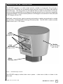
Principles of Operation
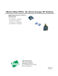
The HDL-64E operates on a rather simple premise: instead of a single laser firing through a
rotating mirror, 64 lasers are mounted on upper and lower blocks of 32 lasers each and the
entire unit spins. This design allows for 64 separate lasers to each fire thousands of times per
second, providing exponentially more data points per second and a much richer point cloud than
conventional designs. The unit inherently delivers a 360-degree horizontal field of view (FOV) and
a 26.8 degree vertical FOV.
Additionally, state-of-the-art signal processing and waveform analysis are employed to provide
high accuracy, extended distance sensing and intensity data. The HDL-64E is rated to provide
usable returns up to 120 meters.
Laser
Emitters
(Groups of 16)
Laser
Receivers
(Groups of 32)
Housing
(Entire unit spins
at 5-15 Hz)
Motor
Housing
Figure 1. HDL-64E design overview.
The HDL-64E employs a direct drive motor system — there are no belts or chains in the
drive train.
.
www.velodyne.com
HDL-64E User’s Manual
2
I n s ta l l a t i o n O v e r v i e w
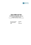
Front/Back Mounting
The HDL-64E base provides two mounting options: side mount and top mount. See Figure 2
for front/back mounting options, Figure 3 for side/side mounting, and Figure 4 for top
mounting instructions.
Four M8-1.25 x 12mm
deep mounting points.
(Four per side, for a
total of 16.)
Mounting
Base
Figure 2. Front and back HDL mounting illustration.
See Figure 2. This figure shows the HDL-64E’s base plate screw locations with threaded inserts
for standard M8 hardware.
.
www.velodyne.com
HDL-64E User’s Manual
3
Side Mounting
Mounting
Base
Figure 3. Side/side HDL mounting illustration.
.
www.velodyne.com
HDL-64E User’s Manual
4
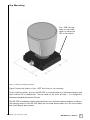
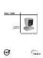
To p M o u n t i n g
Four .406” through
holes for top mount
option to secure the
HDL to the vehicle.
Figure 4. HDL top mounting illustration.
Figure 4 shows the location of four .406” thru holes for top mounting.
For all mounting options, be sure the HDL-64E is mounted securely to withstand vibration and
shock without risk of detachment. The unit need not be shock proofed — it is designed to
withstand standard automotive G-forces.
The HDL-64E is weatherproofed to withstand wind, rain, and other adverse weather conditions.
The spinning nature of the HDL-64E helps the unit shed excess water from the front window
that could hamper performance.
.
www.velodyne.com
HDL-64E User’s Manual
5
Wiring
The HDL-64E comes with a pre-wired connector, wired with power, DB9 serial, and standard
RJ-45 Ethernet connectors.The connector wires are approximately 25’ in length.
Power. Connect the red and black wires to vehicle power. Be sure red is positive polarity. THE
HDL-64E IS RATED ONLY FOR 12 VOLTS. Any voltage applied over 16 volts could damage the
unit. Expect the unit to draw 4-6 amps during normal usage.
NOTE: The HDL-64E does not have a power switch. It spins whenever power is applied.
The HDL-64E has a lockout circuit that prevents its lasers from firing at low RPMs.
Ethernet. This standard Ethernet connector is designed to connect to a standard PC. See the
next section on usage for UDP packet formats.
Serial Interface. The connector also features an RS-232 DB9 serial connector. This connector
allows for a firmware update to be applied to the HDL-64E (Velodyne may release firmware
updates from time to time). It also accepts commands to change the RPM of the unit.
Cable Diagram. If you wish to wire your own connector, refer to Appendix A for a layout of the
wiring pins.
Usage
Data Packet Construction
The HDL-64E outputs UDP Ethernet packets. Each packet contains a data payload of 1206
bytes that consists of 12 blocks of 100-byte firing data followed by six bytes at the end of each
packet that contains a spin counter and firmware version information. Each packet can be for
either the upper or lower laser banks (called “laser blocks”) - each bank contains 32 lasers.
The packet format is as follows:
2 bytes of header info. This header indicates whether the packet is for the upper block or
the lower block. The upper block will have a header of 0xEEFF and the lower block will have
a header of 0xDDFF.
2 bytes of rotational info. This is an integer between 0 and 35999. Divide this number
by 100 to get degrees from 0.
32 laser returns broken into 3 bytes each. Each return contains two bytes of distance
information in .2 centimeter increments, and one byte of intensity information (0 – 255, with
255 being the most intense return). A zero return indicates no return up to 65 meters.
Six status bytes that alternate between packets. The end of the packet will show either:
- A reading showing the internal temperature of the unit. You will see a " DegC " ASCII
string as the last four bytes of the packet. The two bytes before this string are the
thermistor's reading in C in hex 8.8 format. This is in " big indian format" - i.e. the byte
immediately preceding the DegC text is the whole degrees, and the byte preceding that
is the fraction of a degree in 1/256 increments. So if you see c0 1a, the temperature
of the thermistor is 26.75 degrees C.
.
- Or, the version number of the firmware in ASCII character format " Vn.n" where n.n is
the version number, i.e. "1.5".
www.velodyne.com
HDL-64E User’s Manual
6
The HDL-64E data is presented as distances and intensities only. Velodyne includes a packet
viewer called DSR, whose installer files are on the CD that came with the unit. DSR reads in
the packets from the HDL-64E unit, performs the necessary calculations to plot the points
presented in 3-D space, and plots the points on the viewer screen.
Note: The HDL-64E will output three upper block packets for every one lower block packet.
This provides more resolution when identifying objects at greater distances.
The minimum return distance for the HDL-64E is approximately three feet. Returns closer
than this should be ignored.
Correction Angles
Each HDL-64E laser is fixed with respect to vertical angle and offset to the rotational index data
provided in each packet. For each data point issued by the HDL-64E, rotational and horizontal
correction factors must be applied to determine the point’s location in 3-D space referred to by
the return. Each HDL-64E unit comes with its own unique .XML file, called db.XML, that was
generated as a result of the calibration performed at Velodyne’s factory. DSR uses this XML
file to display points accurately. The .XML file also holds the key to interpreting the packet data
for users that wish to create their own interpretation and plotting routines.
db.XML contains 64 instances of the following five values used to interpret the packet data:
rotCorrection: This parameter is the rotational correction angle for each laser, as
viewed from the back of the unit. Positive factors rotate to the left, and negative
values rotate to the right.
vertCorrection: This parameter is the vertical correction angle for each laser, as
viewed from the back of the unit. Positive values have the laser pointing up, and
negative values have the laser pointing down.
distCorrection: Each laser has its own unique distance due to minor variations in the
parts used to construct the laser. This correction factor, in centimeters, accounts
for this variance. This number should be directly added to the distance value read in
the packet.
vertoffsetCorrection: This value represents the height of each laser as measured
from the bottom of the base. It is a fixed value for all upper block lasers and a
different fixed value for all lower block lasers.
horizOffsetCorrection: This value represents the horizontal offset of each laser as
viewed from the back of the laser. It is a constant positive or negative value for
all lasers.
Use the above values from the .XML file to calculate each point’s position in 3-D space. Use the
first 32 points for the upper block and the second 32 points for the lower block. The rotational
info found in the header is used to determine the packets position with respect to the 360
degree horizontal field of view.
Note: There is a file on the CD called “HDL Source Example” that shows the calculations using
the above correction factors.
.
www.velodyne.com
HDL-64E User’s Manual
7
Controlling the Spin Rate
The HDL-64E can spin at rates ranging from 300 RPM (5 Hz) to 900 RPM (15 Hz). The default
is 600 RPM (10 Hz). Note that changing the spin rate does not change the data rate – the
unit will send out the same number of packets (at a rate of one million data points per second)
regardless of spin rate. The image resolution will increase or decrease depending on rotation
speed. See Appendix B for angular resolution figures for various spin rates.
To control the HDL's spin rate, connect the serial cable to an available RS-232 COM port and
issue a serial command of the format #HDLRPMnnn$ where nnn is an integer between 300
and 900. The characters are case sensitive and must be CAPS. The HDL-64E will adopt the
new spin rate. Use the following serial parameters: Baud 9600, Parity: None, Data bits: 8,
Stop bits: 1. The HDL-64E has no echo back feature, so no serial data will be returned from
the HDL-64E.
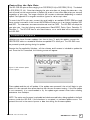
F i r m wa r e U p d a t e
Velodyne may issue firmware updates from time to time. To apply the update, connect the
DB9 RS-232 cable to a standard Windows-compatible PC’s serial port. The HDL-64E must
be powered up and spinning during the update.
Execute the file supplied by Velodyne – all the software and firmware is included to update the
unit. Once the file is executed, the following screen will appear:
Figure 5. HDL software update
screen capture.
Press update and the unit will update. If the update was successful, the unit will begin to spin
down for a few seconds then power back up with the new firmware running. If the first update
is not successful, it is recommended to try the update again several times before seeking
assistance from Velodyne.
NOTE: The entire new firmware is uploaded and checksummed before being applied to the flash
memory inside the HDL-64E. If the checksum is corrupted, no software update occurs. This
protects the unit in the event of power or data loss during the firmware update.
.
www.velodyne.com
HDL-64E User’s Manual
8
Troubleshooting
Use this chart to troubleshoot common problems with the HDL-64E.
Problem
Resolution
Unit doesn’t spin
Verify power connection and polarity.
Verify proper voltage – should be 12 volts
drawing about 3-4 amps.
Remove bottom cover and check inline fuse.
Replace if necessary.
Unit spins but no data
Verify Ethernet wiring.
Verify packet output from another source
(e.g. Ethereal/Wireshark).
No serial communication
Verify RS-232 cable connection.
Unit must be active and spinning for
RS-232 update.
It may take several tries for the update
to be effective.
Service and Maintenance
There are no user service or maintenance requirements or procedures for the Velodyne HDL-64E.
For service or maintenance, please contact Velodyne at (408) 465-2800, or log on to our
website at www.velodyne.com/lidar.
.
www.velodyne.com
HDL-64E User’s Manual
9
Specifications
•
•
•
•
•
•
64 lasers/detectors
360 degree field of view (azimuth)
0.09 degree angular resolution (azimuth)
26.8 degree vertical field of view (elevation) -+2° up to -24.8° down
with 64 equally spaced angular subdivisions (approximately 0.4°)
<5 cm distance accuracy
5-15 Hz rotation rate update (user selectable)
50 meter range for pavement (~0.10 reflectivity)
120 meter range for cars and foliage (~0.80 reflectivity)
>1M points per second
<0.05 milliseconds latency
Laser:
•
•
•
•
•
Class Im - eye safe
4 x 16 laser block assemblies
905 nm wavelength
10 nanosecond pulse
Adaptive power system for minimizing saturation and blinding
Mechanical:
•
•
•
•
12V input (16V max) @ 4 amps
<29 lbs.
10" tall cylinder of 8" OD radius
300 RPM - 900 RPM spin rate (user selectable)
Output:
• 100 MBPS UDP Ethernet packets
Sensor:
.
www.velodyne.com
•
•
•
•
HDL-64E User’s Manual
10
.
www.velodyne.com
H
I
B
A
D E
J
C
F
G
KEY
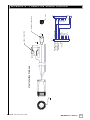
P1
User Interface Harness
P1
GND
12-16VDC (+)
J
I
G
F
C
B
EHTERNET OUT (+) H
EHTERNET IN (+) E
EHTERNET OUT (-) A
EHTERNET IN (-) D
J2
BLK
RED
N/C
N/C
N/C
N/C
CENTER CON.
RED
SHIELD
YEL
J1
SERIAL CONNECTOR
P5
P3
N/C
N/C
N/C
N/C
N/C
N/C
J2
7
8
4
5
3
1
6
2
J1
PIN 1
ETHERNET CONNECTOR
Appendix A - Connector Wiring Diagr am
HDL-64E User’s Manual
11
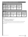
Appendix B - Angular Resolution
Lower Block
RPM
RPS
Points Per
Revolution
Points Per Revolution
Per Laser
Angular Resolution
(degrees)
300
600
900
5
10
15
50000
25000
16667
1562.5
781.25
521
0.2304
0.4608
0.6912
RPS
Points Per
Revolution
Points Per Revolution
Per Laser
Angular Resolution
(degrees)
Post-Lower-Block
Angular Resolution
(degrees)**
5
10
15
200000
100000
66667
6250
3125
2083
0.0576
0.1152
0.1728
0.1152
0.2304
0.3456
Upper Block
RPM
300
600
900
Notes:
The HDL-64E generates 1 million points per second
• The lower block reports 250,000 points
• The upper block reports 750,000 points
There are three upper block packets then one lower block packet reported, then the pattern repeats.
** The first upper block measurement after the lower block measurement reports has half the
angular resolution.
.
www.velodyne.com
HDL-64E User’s Manual
12
A p p e n d i x C - D i g i ta l S e n s o r R e c o r d e r ( D S R )
Digital Sensor Recorder (DSR)
DSR is a 3-dimensional point cloud visualization software program designed for use with the
HDL-64E. It can be located on the CD provided with each HDL-64E sensor. Velodyne offers this
software as an “out of the box” tool for the rendering and recording of point cloud data from
the HDL-64E sensor.
DSR is intended as a reference platform from which the end user can author their own
proprietary adaptation and visualization software packages.
Note: A code snippet is provided on the same CD to aid in understanding the methods at which
DSR parses the data points generated by the HDL-64E sensor.
Installing DSR
Locate the DSR executable program on the provided CD. Double click on “DSR-1.1-2-install
3.exe” to begin the installation onto the host computer. Use of the default settings during the
installation is highly recommended.
When the installation is complete, follow the “Utilizing the db.xml calibration data file in DSR”
instructions in the next section to calibrate the DSR viewer to your new sensor.
Note: failure to use the calibration db.xml file supplied with your sensor will result in sub-optimal
point cloud rendering in DSR.
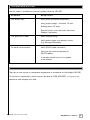
Using DSR
DSR gives the user the ability to view point cloud data in real time or to create a recording of
such data for future reference and playback. The recorded data will be stored in a standard
pcap file format.
Note: These files can become quite large so the user should be mindful of recording duration
when created.
Live Playback:
For live playback, first secure and power up the HDL-64E sensor so that it is spinning. Connect
the RJ45 Ethernet connector to your host computer’s network connection. You may wish to
utilize auto DNS settings for your computers network configuration.
DSR desktop icon =
Open DSR from your desktop icon created during the installation. Pull down the “Options”
menu and select the proper input device. Go to “Options” again and deselect the “Show Ground
Plane” option. (Leave this feature off for the time being or until the ground plane has been
properly adjusted).
.
www.velodyne.com
HDL-64E User’s Manual
13
You can now go to “Options/Properties” to change the individual settings for each LASER
channel if so desired.
REFRESH button =
Provided that your computer is now receiving data packets, click on the Refresh button to start
live viewing of a point cloud. The initial image is of a directly overhead perspective. See page 17
for mouse and key commands used to manipulate the 3D image within the viewer.
Note: The image can be manipulated in all directions and become disorienting. If you lose
perspective, simply press F1 to return to the original view.
Recording Data:
RECORD button =
Once the input of streaming data has been confirmed through the live playback feature, click on
the Record button and the program will request the name and location for the pcap file to be
created. The recording will begin immediately once the file information has been entered. Click
on the Record button again to discontinue the capture. One can string multiple recordings
together on the same file by performing the Record function repeatedly. A new file name will
not be requested until after the session has been aborted.
Note: An Ethernet capture utility such as Wireshark® can also be used as a pcap capture utility.
Playback of Recorded files:
Use the File ➝ Open command to open a previously captured pcap file for playback. The DSR
playback controls are similar to any DVD/VCR control features.
PLAY button =
PAUSE button =
Press the Play button to render the file. The Play button will alternate to Pause when in
playback mode.
FORWARD button =
REVERSE button =
Use the Forward and Reverse buttons to change the direction of playback.
Note: The X, Y, Z and distance figures at the bottom of the image represent the distance of
the x,y,z crosshairs with respect to the origin point indicated by the small white circle.
Note: In live display mode, click on the double arrow button to begin display. The concentric
gray circles and grid lines represent 10 meter increments from the sensor, which is depicted
on the screen by a white circle.
.
www.velodyne.com
HDL-64E User’s Manual
14
Utilizing the db.XML calibration data file in DSR
The db.XML file provided with your Velodyne HDL-64E contains all of the necessary data for the
proper alignment of the point cloud information gathered by the HDL sensor for each laser.
{vertical correction (deg), rotational correction (deg), distance correction (cm), vertical offset
(cm), horizontal offset (cm), minimum and maximum intensity (0-255)}.
When implemented properly, the image viewable from the Digital Sensor Recorder (DSR) will be
properly calibrated to provide an accurate visual representation of the environment in which the
sensor is being applied.
This data should also be used in any other program using the data generated by the HDL-64E.
To i n t e g r a t e t h e d b . X M L f i l e i n t o t h e D S R p r o g r a m ,
— follow these steps.
1. Provided that DSR has been installed on the host computer using the default settings,
follow this path: c:\program files\Digital Sensor Recorder
2. Cut and paste the existing db.XML file to another location and rename as the
default_db.XML
3. Copy and paste the db.XML file provided on the CD to the DSR program folder
previously opened
4. Close out the windows and the program is ready to run
5. Open the DSR program
6. Click options\properties
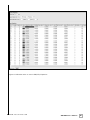
7. Check that the new values are present and that they reflect the values in the
example screen captures provided on the CD [Fig.6]
8. Your DSR viewer is now calibrated to your sensor
.
www.velodyne.com
HDL-64E User’s Manual
15
Figure 6. Calibration values as seen in DSR/File/Properties
.
www.velodyne.com
HDL-64E User’s Manual
16
DSR Key Controls
Zoom:
Z = Zoom in
Shift, Z = Zoom out
Z axis rotation:
Y = Rotate CW
Shift, Y = Rotate CCW
X axis rotation:
P = Rotate CW
Shift, P = Rotate CCW
Y axis rotation:
R = Rotate CW
Shift, R = Rotate CCW
Z Shift:
F = Forward
B = Back
X Shift:
L = Left
H = Right
Y Shift:
U = Up
D = Down
Aux. Functions:
Ctrl, (Z,Y,P,R,F,B,L,H,U,D) Direction = Fine Movement
Alt, (Z,Y,P,R,F,B,L,H,U,D) Direction= Very Fine Movement
DSR Mouse Controls
Rotational:
Left Button/Move
Slide:
Right Button/Move
Zoom:
Scroll forward = Zoom In
Scroll backward = Zoom Out
.
www.velodyne.com
HDL-64E User’s Manual
17
Velodyne Acoustics, Inc.
345 Digital Drive
Morgan Hill, CA 95037
408.465.2800 voice
408.779.9227 fax
408.779.9208 service fax
www.velodyne.com
Service E-mail: [email protected]
Product E-mail: [email protected]
Technical E-mail: [email protected]
Sales E-mail: [email protected]
.
63-HDL-64E Rev D MAR08
www.velodyne.com
Trademarks are property of their respective owners.
HDL-64E User’s Manual
18