1
PERIPHERALS
MODULE 8
MK8-SVMOD-0002
PERIPHERALS
©2002 BALLY GAMING AND SYSTEMS ALL RIGHTS RESERVED
Bally Gaming and Systems
6601 South Bermuda Road, Las Vegas, NV 89119
For Customer Service and information:
+1-702-896-7772 Outside the U.S.
1-877-GO-BALLY (877) 46-22559 in the U.S. and Canada
896-7772 in Las Vegas
FAX: +1-702-896-7710
or visit our website at http://www.ballygaming.com
Peripherals
Module 8
Peripherals Table of Contents
Coin Acceptors ........................................................................................................................... 5
Coin Mechanisms, Inc. CC-16 ................................................................................................................................ 5
Coin Mechanisms, Inc. CC-62 ................................................................................................................................ 6
Coin Mechanisms, Inc. Micro Comparitor MC ....................................................................................................... 7
Money Controls Condor CN103 ............................................................................................................................. 8
National Rejectors, Inc. G-13, 0000 ....................................................................................................................... 9
IDX, X-10 and X-70 X-Mark Xeptors ...................................................................................................................... 9
Bill Acceptors ........................................................................................................................... 13
JCM® WBA-SS .................................................................................................................................................... 13
JCM® SENTRY™ - Intelligent Bezel .................................................................................................................... 16
JCM® DBV-200 .................................................................................................................................................... 18
Mars ZT Series 1000 ............................................................................................................................................ 20
Money Controls Ardac WACS .............................................................................................................................. 24
Hoppers ..................................................................................................................................... 25
Bally Gaming and Systems XS-1200 ................................................................................................................... 26
Asahi Seiko DH-750 ............................................................................................................................................. 29
Ticket Printers .......................................................................................................................... 36
Ithaca Series 70 Impact Ticket Printer .................................................................................................................. 36
Ithaca Series 700 Thermal Ticket Printer ............................................................................................................. 40
Seiko PSA-66 Thermal Ticket Printer ................................................................................................................... 42
Accounting System Interface .................................................................................................. 44
Accounting System Settings ................................................................................................... 47
©2002 Bally Gaming and Systems
8-3
Peripherals
Peripherals
8-4
©2002 Bally Gaming and Systems
Peripherals
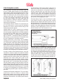
Coin Acceptors
Coin Mechanisms, Inc. • 400 Regency Drive,
Glendale Heights, Illinois 60139-5128 • Toll
Free: (800) 323-6498 Phone: (630) 924-7070
Fax: (630) 924-7088 • www.coinmech.com
1. Inhibit input - 12VDC models only
All other models - Triac load
2. Sense output
1
3. 48 Volt
2
4. 24 Volt
3
5. 12 Volt
4
6. Ground
5
6
CC-16
Power Requirements:
fixed VDC models, 11.5
to 12.5 VDC
Feed Rate: 7 coins per
second (models CC-16,
CC-62, MC-16):
Designed for coin
CC-16
diameters of .700"
(17.8mm) to 1.575 (40mm). Wide Body model
recommended for coin diameters up to 1.95"
(49.5mm).
Operating temperature recommended: 0o to 60oC.
Installing the Sample Coin (models CC-16, CC62, MC16): Looking at the front of the comparitor, slide (without lifting) the sensor coil assembly to the right. Replace the sample coin (or chip) with the desired coin
(or chip) and then carefully release. In most cases, the
coin (or chip) will automatically seat itself. When properly seated, the coin (or chip) will rest parallel between
the sensor coil assembly and between the ribs on the
rail insert.
Replacing an Existing Mechanical Acceptor (models
CC-16, CC-62, MC-16):
1. Remove the acceptor.
2. Disconnect the coin return linkage.
3. Remove the lockout coil (if used).
4. In some cases, the comparitor mounting studs may
need to be relocated to meet manufacturer’s
mounting specifications.
Potentiometer Adjustment (models CC-16, CC-62):
Each comparitor is adjusted to give excellent discrimination against slugs. However, some high quality slugs may
need a finer adjustment.
1. Adjust potentiometer clockwise (CW) until high quality slug is rejected.
2. Drop good coins to ensure accurate acceptance.
3. Repeat steps 1 and 3 if necessary. For further potentiometer adjustment procedures, call or fax Coin
Mechanism, Inc.’s service department and request
document #09300072.
Before Turning Power On (models CC-16, CC-62, MC16):
1. Make sure that all connections are properly insulated.
2. Tuck wire to prevent interference with coin travel or
coil armature movement.
3. Check the power cord for firm connection to the PC
board.
4. Make sure the comparitor is mounted securely in the
equipment.
5. Check the entry chute alignment by inserting the
proper coin. The coin should fall freely, without stopping, through the comparitor and reject out of the
equipment.
After Turning Power On (models CC-16, CC-62, MC-16):
5. Mount comparitor into equipment, ensuring that
coin entry and coin exit are aligned.
Wiring Instructions: The CC-16 printed circuit board
requires a 6-pin JST terminated interface. The connector diagram following denotes the typical voltage
line pinouts to the printed circuit board:
©2002 Bally Gaming and Systems
1. The LED will illuminate when voltage is applied.
2. Drop good coins. They should be recognized by the
comparitor and accepted.
3. Repeat step 2 several times to ensure the unit is functioning properly.
8-5
Peripherals
inhibit is its ability to electronically inhibit the validator
without removing power from it, thereby eliminating any
power-up time delay. The inhibit condition is accomplished by disabling only the accept coil.
Coin Acceptors (cont.)
CC-62
Power Requirements: Voltage Range, 11.5 to 12.5 VDC.
The inhibit line is wired to pin #7 of the printed circuit board.
Designed for coin diameters of .700" (17.8mm) to 1.575
(40mm). Wide Body model recommended for coin diameters up to 1.95" (49.5mm).
Coin Sense Output Feature: The CC-62 sends a coin sense
output pulse when the sensing coils detect a good coin.
This pulse is sent on pin #2 of the printed circuit board.
LED Credit Output Feature: The CC-62 sends a credit
pulse from the optics when a good coin has passed.
This pulse is sent on pin #4 of the printed circuit board.
Tilt/Error Signal Feature: Another security feature of the
CC-62 is its ability to protect against stringing. The optics are positioned in an A-Over-B pattern. This means
that a coin must first block then uncover both the top
and the bottom optic before a credit pulse is issued. If
the bottom optic is blocked before the top, the CC-62
issues a tilt pulse on the tilt/error output line. The error
signal, which is on the same output line, is used in the
event of a failed or blocked optic. In the event an optic
is blocked for a period of more than 1.5 seconds, the
tilt/error output line goes low and will remain low for as
long as the failed or blocked optic remains.
CC-62
Wiring Instructions: The CC-62 printed circuit board requires a 7-pin AMP right angle locking connector interface.
1.
2.
3.
4.
5.
6.
7.
Ground
Coin Sense
Error
Credit
Key
12 Volt
Inhibit
1
2
3
4
5
6
7
The built-in tilt/error detection line can be utilized by wiring to pin #3.
Denomination Adjustment: As with any comparitor product
it is essential that the proper dampener lever and weight
assembly are used for the size coin being validated. For
the CC-62 there is an additional adjustment step that is
critical to proper operation. This adjustment is to the
adjustable guide rail. The adjustable guide rail ensures
that a good coin, once accepted, adequately passes the
optics as it exits the validator body.
Operating Voltage: The neutral or ground (GND) of the
voltage source should be wired directly to pin #1 of the
printed circuit board.
The hot or positive 12-Volt DC of the voltage source is
wired directly to pin #6 of the printed circuit board. These
connections now provide the operating voltage to the
comparitor.
To perform this adjustment, loosen the rail screw on the
adjustable guide fail, as well as the elastic nut on the
rail support bracket. Position the bottom of rail so that
you have the full diameter of the coin’s width, plus 1/32"
over. This guarantees proper optic blockage for the size
coin being validated. After adjusting rail, make sure to
fully tighten the rail screw to hold the adjustment made.
Proceed by aligning the tip of the rail support bracket to
the end of the rail, then tighten the elastic nut in place.
Two Separate Outputs: When the sensing coils sense
a good coin, a pulse is sent out to the host machine.
Following this, the accept gate opens, and as the coin
passes the LED optics a credit pulse is also sent out to
the host machine. Together these two pulses provide
optimum security against cheating. The host machine
can be configured to recognize a valid coin only when
both outputs have been detected.
NOTE: An adjustment gage tool may be
purchased from Coin Mechanisms
directly by calling the Parts Sales
department at (630) 924-7070 and
requesting part number #06660003.
The LED optics have been positioned such that coins
falling edge-to-edge are guaranteed to be accepted
without stealing.
Inhibit Feature: The CC-62 has an inhibit feature built-in
to its electronics. The unique feature about the CC-62
Peripherals
8-6
©2002 Bally Gaming and Systems
Peripherals
signal, and the lengths of the pulses can be changed to
accommodate different machine requirements.
Additionally, a NULL signal is an internal signal
generated when a valid coin passes the sensor coils. If
this NULL signal is too long (> 250ms as sometimes
occurs when stringing) the TILT line will output a signal.
If any of the optics are blocked for 1.5 seconds or longer
the TILT line will be active until the condition is corrected.
If a coin is detected moving past the optics in a reverse
direction (stringing) a TILT pulse occurs. If a coin passes
the optics without a matching sense pulse a TILT occurs
(note 1). The mechanism will not accept coins when
the TILT line is active.
Coin Acceptors (cont.)
Micro Comparitor MC
(Replacement for
CC-16 and CC-62)
Designed
for
coin
diameters of .700"
(17.8mm)
to
1.47"
(37.34mm). Wide Body
model recommended for
coin diameters up to
1.950" (49.5mm).
Credit Signal: The CREDIT signal is an output which
occurs for every valid coin that is accepted properly
through the mechanism. A CREDIT is generated by the
internal microcontroller only when a valid sense pulse
is matched with a corresponding optic pulse. This close
control between the sense signal and the optic signal
allows more accurate monitoring of coins through the
mechanism. The CREDIT signals are buffered and
therefore are fixed in length and duty cycle regardless
of coin feed rate.
Wiring Instructions: The
MC-16
printed circuit board is
available with one of two possible connectors. A 7-pin
Molex header is used when emulating a model CC-62;
a 6-pin JST header is used to emulate both the CC-16
and CC-40.
Operating Voltage: There are two different models offered, a 12 Volt DC only model, and a multi-voltage
model which allows for operations from 20 to 40 Volts
DC, or 20 to 30 Volts AC.
Sense Signal: The SENSE signal is an output which
simply indicates that a valid coin has passed the sensor
coils. It is available for those applications requiring a
pre-count or verification that valid coins have entered
the device.
Bi-Color Status Indicator: The MC-16/40/62
incorporates a bicolor (green / red) LED on its front cover
to easily indicate the operating status of the mechanism
visually. The LED will be green when power is applied
to the device and it is enabled (INHIBIT not active) to
accept coins. The LED will be red if the INHIBIT line is
active (disable coin acceptance) or if there is no resident
coin in place. The LED will also change to red when the
TILT line is active (error condition). When the LED is
red the device will not accept coins.
CC-16 Emulation
CC-62 Emulation
Inhibit Input Feature: The INHIBIT feature is an input
which allows you to disable the device without removing
power from it. The INHIBIT pin can be configured to
accept either a LOW or HIGH level signal to inhibit the
device.
Tilt Output: The TILT signal is an output which alerts
the machine of a malfunction or tampering of the device.
There are different conditions which will generate a TILT
©2002 Bally Gaming and Systems
8-7
Peripherals
Coin Acceptors (cont.)
Money Controls • New Coin
Street, Royton Oldham OL2
6JZ United Kingdom • Phone:
+44 161-6780111 Fax: +44 161-6267674 •
www.moneycontrols.com
Condor CN103
Power Requirements: Voltage, 12 VDC to 32 VDC
Operating temperature: 0°
to 60° C.
Maintainable life of 20 million coins.
Security: The acceptance window can be adjusted to
increase fraud rejection or increase coin acceptance.
Coinage: Accepts coins
within the diameter range
CN103
of .59-1.75" (15-44.5 mm)
and the thickness range of .059-.148" (1.5-3.75 mm).
Wiring Instructions:
Connector 1
Pin 1 Inhibit all
Pin 2 VACS +6V
Pin 3 +12 to 32 VDC
Pin 4 +12 to 32 VDC
Pin 5 +12 to 32 VDC
Pin 6 +0V
Connector 2
Pin 1 Accept (b) NPN generation
Pin 2 VACS NPN
Pin 3 Alarm
Pin 4 Error
Connector 3
Serial Port
Connector 4
LCD display
Alarm: Open collector NPN is activated for 2 seconds
with inhibit all. This condition occurs when coins travel
in reverse, too slowly or block the opto beams. A continuous yellow LED will result for the duration of the alarm.
During this time a pulse will appear on the error pin.
Error: When a critical failure is detected at power up a
500ms pulse will be given on the error line and will repeat every 2 seconds. The LED will flash red and all
coins will be inhibited.
Teach and Run™ Programming: Follow these steps to
program:
Peripherals
8-8
©2002 Bally Gaming and Systems
Peripherals
IDX, Incorporated • 400 W. Cedar St. • El
Dorado AR 71730 • Ph: (800) 643-1109
FAX: 870-862-3472 • http://www.idxinc.com
Coin Acceptors (cont.)
National Rejectors, Inc. GmbH • Postfach
1461 • Buxtehude 21604, Germany • Phone:
+49 41 617 290 Fax: +49 41 617 29115 •
www.nationalrejectors.com
X-10 and X-70 X-Mark Xeptors
The X-10 and
X-70 X-Mark
Xeptors are multi-coin
acceptors which can be
field programmed to
distinguish and accept any
of up to six coins or tokens.
Multi-coin acceptance
offers the possibilities of
mixing promotional tokens
with standard tokens,
X-10 X-Mark Xeptor
accepting older tokens with
new tokens in the process
of change-over, or
replacing expensive (4x)
hopper fill real currency
with economical tokens.
Precision
diameter
measurement totally
eliminates shaved coin
acceptance problems. Its
built-in
multi-color
indicator LED provides
operational status and
X-70 X-Mark Xeptor
field
diagnostic
information. Its novel Personality Plug modules ensure
plug compatibility in field retrofit applications.
G-13, 0000
Power Requirements: 12
VDC +3/-1 Volts tolerances
Operating temperature 0°
to 55° C.
Acceptance: Up to six different coins.
G-13, 0000
Diameter: between .59” and 1.22” (15 and 31mm).
Thickness of coins: between .059” and .1” (l.5 and 2.6
mm)
Dimensions: Height 4” (102 mm) Width 3.5” (89 mm)
Depth 2” (52 mm)
Temperature range: 0o C up to +55o C
Coin inhibit: A common blocking line for all coins is
available. Single coin inhibit may be achieved by DIP
switches on the G-13.
Measuring principle: Three inductive sensors are
arranged to detect material, thickness, diameter and
embossing of coins as they pass. The passing coin
activates the sensors, providing different voltage
measuring values. These voltages are digitized and
processed within the microprocessor.
Features:
• Distinguishes and accepts any of up to six different
coins or tokens.
• Reads multiple X-Mark codes and optionally detects
Programming of acceptor: A standard computer (IBM PC
or compatible) allows programming of the acceptor for
any coin acceptance. Programming means just the insertion of a coin which should be accepted. Please refer
to the document “Use of program PROEMP.”
Wiring
1. Ground
2. +12 VDC
3, 4, 7, 8, 9, 10. Coin Signals*
5. N.C.
6. Coin Inhibit
the presence of SmartMark.
• Diameter ranges: X-10: 0.650" to 1.490" (16mm to
38mm), straight drop configuration, X-70: 1.330" to
1.950" (34mm to 49mm) reverse drop configuration
• Actually measures coin diameter to +/-.005" typ (X10), +/-.007" typ X-70).
9
7
5
3
1
10
8
6
4
2
• Measures metal alloy 3 ways.
Wire Insertion View
• Accepts up to 16 coins per second (X-10), 10 coins
per second (X-70).
*Coin Signals: <.07 volts active low / 150 mA Open collector NPN. I max = 150 mA, Umax = 35
volts. Time of pulses: 100 msec +/- 10%.
• Slide on access covers shed spilled liquids.
• Built-in coin release and opening coin chute.
©2002 Bally Gaming and Systems
8-9
Peripherals
special interface requirements are easily satisfied with
new Personality Plugs designed specifically for the job.
With the correct personality plug installed in an Xeptor,
retrofit installation requires no machine connector
rewiring. The tables below can help in deciding which
personality plug to use. Refer to the Electrical
Specifications table following for each pin definition.
Coin Acceptors (cont.)
• New coin types can be field programmed without
extra equipment.
• Multi-color indicator LED for operational status and
field diagnostics.
Personality Plugs Table
• Universal electrical interface compatibility with
existing legacy machines and new machines via
Personality Plug modules.
LED Status Indicator
• No light indicates no power. Plug it in, check your
wires, check your power supply. Verify your
Personality Plug.
• Solid green means normal operation for either switch
position 0 (Run) or switch positions 7 to F (Field Test).
• Green with short red flash means the unit is normally
Personality
Plug Model
P P 16
PP16IC
PPU N I
PPNRI-6
PPNRI-3
Compatibility
Connector
CC-16
JST-6
CC-16 12V
JST-6
Universal
JST-6
NRI
10pin IDC
NRI
10pin IDC
Pi n 1
1K to Gnd.
Inhibit
Inhibit
Ground
Ground
Pi n 2
Sense
Sense
/Coin Optics
12V D C
12V D C
Pi n 3
48 VDC/AC
----
----
/Output5
----
Pi n 4
24 VDC/AC
24 VDC/AC
24 VDC/AC
/Output6
----
Pi n 5
12 V D C
12 V D C
----
Coin Return
----
Pi n 6
Ground
Ground
Ground
Inhibit
Inhibit
Pi n 7
/Output1
/Output1
Pi n 8
/Output2
/Output2
Pi n 9
/Output3
/Output3
P i n 10
/Output4
----
Electrical Specifications
operating and is secured from coin programming
without using the X-Key. This is available starting with
V3.0r firmware.
SIGNAL
• Solid red is normal in switch positions 1-6 for coin
programming. A red flash during coin acceptance
indicates credit has issued.
• Alternating red-green means that the unit has detected
some sort of malfunction. See Field Test to diagnose.
INHIBIT
Inhibit = float or >3.5VDC, Enable = < 1.0VDC
SEN SE
Active high 32ms pulse, PNP 12V pull-up 10mA max, 3.3K pull-down.
/SENSE
Active low 32ms pulse, NPN sinking 10mA max, 47K 5V pull-up.
/CREDIT
Active low 32ms pulse, NPN sinking 10mA max, 47K 5V pull-up.
/TILT
Active low >32ms pulse, NPN sinking 10mA max, 47K 5V pull-up.
/OUTPUT-n
Active low >32ms pulse, NPN sinking 10mA max, 47K 5V pull-up.
RELAY
• Blinking yellow means Inhibit. It is inhibited from
acceptance in switch position 0 ,inhibited from coin
programming in switch positions 1-6, and Credit
Optics not available in switch position 8.
ELECTRICAL CHARACTERISTICS
(Note: Pulse w idths programmable via "P" command on serial port)
Relay contact terminal. 40V 0.2A peak rating..
/Coin Optics
Wire-OR optics output enable, 100ms low pulse, 100K 12V pull-up.
48VDC/VAC
Power input 38 to 55VDC, 38 to 55VAC, 35mA max @idle.
24VDC/VAC
12V D C
1K to Ground
Ground
Power input 14 to 32VDC, 16 to 32VAC, 35mA max @idle.
Power input 11.5 to 16VDC, 25mA max @idle, 240mA accept gate.
1K 1W resistor to circuit ground. (for triac holding current)
Circuit common.
Personality Plugs
Field Tests and Diagnostics
Personality plugs are
small
connector
conversion modules about
as big as the last segment
of your little finger. They
are used to convert the 8pin header in the Xeptor
to any of many available
connector styles and pin
assignments common in
the industry. For example, there is one personality plug
type for each of the older Coin Mechanisms CC-series
acceptors and the NRI multi-wire output acceptors.
Additionally, many have been designed to meet the
needs of specific OEMs, including such things as
simulation of OEM credit optics module signals. Other
Peripherals
The normal operation mode of the Xeptor is with the
rotary switch position #0 where the LED is green. If the
LED is flashing yellow, it means that the Xeptor is
inhibited. This can be caused by an external control line
such as from a door switch or otherwise as controlled
by the machine that it connects to. It may also (although
less likely) be caused by improper setting of the Inhibit
bit in the SysConfig control byte. If the LED is alternating
red-green, it indicates a malfunction has been detected.
Some malfunctions can be corrected in the field.
Gate Relay Test (rotary switch #0): Press the test button
to activate the gate relay. If it does not activate, it may
be physically obstructed or its wire unplugged. This
would be one cause for rejection of all coins.
8-10
©2002 Bally Gaming and Systems
Peripherals
The Xeptors will not “speak unless spoken to” except
when a coin has been deposited. The Xeptor will
automatically report the disposition and sensor readings
taken from each coin when the analysis is complete and
the SENSE pulse has been issued. If internal credit optics
are installed, a subsequent report on slow or reverse coins
may additionally occur. The auto report message consists
of 6 data bytes in ASCII Hex format.
Coin Acceptors (cont.)
Inductive Metal Sensor Tests (rotary switch #E, #F): Turn
the rotary switch to positions #E and #F to test the
inductive sensor. Normal LED color is green. A red color
most often indicates either there is metal in front of the
inductive sensors or that the flat cable going to the small
sensor housing has been unplugged.
Diameter Optics Sensor Tests (rotary switch #B, #C,
#D): Turn the rotary switch to positions #B, #C, and #D
to test each of the three diameter through-beam optical
sensors. Normal LED color is green. A red or orange
color most likely indicated either there is an object or
dirt blocking one of these three sensors and cleaning of
the coin cute is required, or that the flat cable going to
the small sensor housing has been unplugged.
Report Command
The “R” REPORT command produces a list of all the
critical operational parameters of the Xeptor (see
example following). In the first line, the software version
is identified and the ID# of the unit is reported. The next
eight lines report the detail contents of each of the six
coin memories. The bits of the options byte are defined
in the following table:
X-Mark Code Optics Sensor Calibration (rotary switch
#9, #A ): Fold a piece of white paper twice (to 4
thicknesses) and insert it into the center of the coin
chute. Turn the rotary switch to position #9 (rear side
optics) and press the test button. The unit will use
information gathered to calibrate the sensitivity of its
reflective sensors for reading the X-Mark optical code
on tokens. The LED should be an orange color after
calibration. Repeat for switch position #A (front side
optics). When you remove the paper, the LED should
be green in both of the switch positions.
Example Configuration Report and Coin Auto Report Messages.
Xeptor 30 (d) ID#: 1F5E -Firmware version and ID#
Coin Memory: 01 02 03 04 05 06
Coin Pulses: 0D 01 00 01 00 00
Token Code: 00 00 00 03 00 00
E-Metal S:
26 24 00 24 00 00
E-Metal A:
2E 2C 00 2C 00 00
C-Metal A:
2E 2C 00 2C 00 00
Diameter:
D9 DA 00 DC 00 00
Options:
01 01 00 81 00 00
Thresholds: 05 07 03 06 03 05 08 00 00
Tank Calib: 47 Tank Now: 47 51
Sys Config: 08 Tilt Time 1/3 sec: 09
Credit ms: 20 Divert Dly/Pls ms:
10 50
2 23 2D 2C D9 00
2 25 2C 2C DC 00
2 24 2C 2D DA 00
4 24 2D 2D DB 03 - Distinguished by X-Mark from #2
D 35 3E 3E 1E 00 - Failed on diameter
2 23 2D 2C D9 00
2 25 2C 2C DC 00
M 2A 30 30 DA 00 - Failed on edge metal
4 25 2C 2C DC 03
4 24 2C 2D DA 03
4 24 2D 2D DB 03
U 26 2D 2E D6 00 - Unwanted close slug for #2
U 27 2E 2D DA 00 - Unwanted close slug for #2
I 00 00 00 00 00
I 00 00 00 00 00 - Xeptor inhibited
I 00 00 00 00 00
2 23 2D 2C D9 00
2 25 2C 2C DC 00
2 24 2C 2D DA 00
S 00 00 00 00 00 - Coin took too long in coin chute
R 00 00 00 00 00 - Wrong exit after credit issue.
4 24 2C 2D DA 03
4 24 2D 2D DB 03
2 23 2D 2C D9 00
2 25 2C 2C DC 00
2 24 2C 2D DA 00
4 24 2D 2D DB 03
Credit Sensor Test (rotary switch #8): The credit optics
(if installed) are located just above and below the gate
relay rake. If they are not installed the LED will flash
amber to indicate that the credit optics were not detected
at power-up. If they are installed, the LED is normally
green for proper function, and will become orange to
red as they become blocked by dirt or other obstructions.
Memory Test (rotary switch #7): Turn the rotary switch
to positions #7 to test the validity of memory. Normal
LED color is green. A red color indicates that memory is
corrupted. It may be possible to correct this by relearning
the coins. If not, the memory chip
Disposition
is defective.
Edge Metal S
Edge Metal A
Auto Reporting
Center Metal
Diameter
Token Code
3
24
2B
2B
DC
03
Auto report from a coin matching coin memory #3.
The coin has the same edge and center metal, a
diameter of 1.464” and an X-Mark code of 03.
©2002 Bally Gaming and Systems
Note: The internal sequence for parameter checking is 1.) diameter,
2.) code, 3.) edge metal-S, 4.) edge metal-A, 5.) center metal.
Coin memory is checked in the order of 1-6 for a match.
8-11
Peripherals
to read minted-in codes on the surface of the coin. To
benefit from these new measurement capabilities we
must also do a little better in coin position control than
formerly required when only metal alloy was being
measured. One cannot expect imprecise coin position
control to allow precise and repeatable measurement
of the coin properties any more than one could expect
an accurate measurement of the length of a fish if you
won’t put the ruler up against the fish.
Coin Acceptors (cont.)
The “Thresholds” line shows the sensitivity levels set
for the 4 X-Mark optical sensors, the three diameter
optical sensors, and the two credit optics sensors. These
values will be between one and eight normally. The “Tank
Calib” line shows the value of the inductive sensor
reading when the last “learn” was performed, and what
it is now in two different configurations. These should
be in the 40s or higher. The “Sys Config” byte will
normally be 00 for “inhibit low” and 80 for “inhibit high”
on the Inhibit input line. The remaining timing values
should be self explanatory.
Thickness Setup: Figure 1 of the X-10 Xeptor is a side
view showing a series of eight holes and a sliding
adjustment with a detent that centers itself over one of
the selected holes. The dimensions referring to each of
the eight holes is the chute thickness achieved at each
position of the sliding adjustment. A good rule of thumb
would be to set the adjustment for .010" to .020" more
than the thickest coin in the intended coin set.
View the Report Screen: Send the “R” command to see
the coin data stored in memory and the operating
parameters for various sensors and the timing of the
credit pulse and other signals.
Change Inhibit Line Logic|: Xeptors have a hardware
inhibit line that is used to prevent acceptance of coins
even when power is applied to the unit. When inhibited,
the Xeptor LED will flash amber color to indicate the
inhibit state. Send the “I” command to change to “inhibit
high” or send the “i” command to change to “inhibit low”.
After doing so, you must send the “S” command to save
the new configuration to nonvolatile memory.
Change Credit Pulse or Tilt Timing: The “Pccddddtt”
command is used to change the output credit pulse width
(cc), the diverter output option delay and pulse width
(dddd) and the tilt time. Assuming you do not have a
diverter option and you would like the credit pulse to be
34ms (22 hex) and the self inhibit after a tilt to last four
seconds (12/3 sec Þ 0C hex) then you would enter the
command “P2200000C”, followed by the “S” command
to save the new configuration to nonvolatile memory.
Figure 1
Diameter Setup: To control coin centering over the
optical and inductive sensors, install the appropriate pair
of clip-on coin chute edge guides as shown in Figure 2.
The resultant coin chute width should be no more that
about .060" wider than the coin if it has X-Mark codes.
Without X-Mark codes, it may be as much as .23" wider.
A single drop of silicone adhesive is recommended on
each to ensure they are not accidentally knocked out.
Increase X-Mark Code Reading Security: Use this
command to cause the Xeptor to increase the X-Mark
reading security (have higher standards for acceptance)
to knock out tokens which may have minted text or
graphics which may, at least in part, mimic X-Mark facet
reflections (only V3.0p or after). Bits 4 and 5 in the
SysConfig byte control the X-Mark reading security
features. Assuming that the inhibit logic is set for inhibit
high (stored in bit 3 of SysConfig) and you wanted to
set both X-Mark reading security bits (which raise the
signal threshold level and require the mark be seen on
both the leading and trailing edge of the coin), you would
send the command “s38” followed by the “S” command
to save the new configuration to nonvolatile memory. If
you additionally wanted tighter metal alloy tolerance,
use “s78”.
Thickness and Diameter Adjustment: The X-10 Xeptor
significantly raises the ability to measure and
discriminate between coins through precision optical
diameter measurement sensors, edge and center of coin
metal alloy measurement, and X-Mark optical sensors
Peripherals
Figure 2
8-12
©2002 Bally Gaming and Systems
Peripherals
Bill Acceptors
JCM American Corporation • 925 Pilot
Road, Las Vegas, NV 89119 • Tel: (702)
651-0000, Toll Free: (800) 683-7248, Fax:
(702) 644-5512 • www.jcm-american.com
JCM® WBA-SS
Figure 3
Power Requirements: Voltage
Range, 95 to 135 VAC with power
supply 50 to 60 Hz, or 12 VDC max
20 VA.
Bill Jams: Remove jammed bills from the bill head by
moving the release catches on both sides of the head
towards you. Open the acceptor head to access the
jammed bill (Figure 4).
Magazine capacity 600 notes.
Operating temperature recommended 0° to 45° C.
WBA-SS
Adjustable Bill Slot: The WBA-SS has the ability to read a
wide range of bill sizes. Four adjustment guides are available for bills that are 65 mm to 80 mm wide (Figure 1).
Figure 4
Remove jammed bills from the transfer area by pulling
the access lever and opening the top cover (Figure 5).
Figure 1
Collecting Bills: Collect bills by pressing the release lever and pulling the stacker box towards you (Figure 2).
Figure 5
Figure 2
Occasionally, a bill jams near the inlet of the stacker box.
Push the release lever of the stacker box and remove it
to access the jammed bill (Figure 6).
Open the stacker box cover and remove the bills inside
(Figure 3).
©2002 Bally Gaming and Systems
8-13
Peripherals
US dollar ($) DIP Switch Settings
Bill Acceptors
ON
OFF
1
SW-1
DIR
2
3
SW-2
$1
4
5
6
WBA-10/11/12/13 ID-003
SW-3
SW-4
SW-5
SW-6
$5
$10
$20
$50
7
SW-7
$100
8
SW-8
OFF
(DIR) "ON": 2-WAY ACCEPTANCE {IF WITHIN FIRMWARE}
"OFF": 4-WAY ACCEPTANCE {IF WITHIN FIRMWARE}
Troubleshooting
Description
Figure 6
Interface: The WBA-SS uses an ID-003 interface. The
ID-003 interface is a bidirectional serial interface. The
machine is able to receive status reports from the WBA
in response to appropriate commands (Figure 7).
Bill Rejection
Probable Cause
Possible Solution
DIP switches not set properly
Set DIP switches
Roller and/or belts are
excessively dirty
Clean head and rollers with mild
soap and water solution
Denomination disabled on
game
Check game options
Credit limit not set properly on
game
Set credit limit for proper
acceptance
Cashbox is full, or not installed
properly
Check and verify cashbox
condition
Sensors out of calibration, unit
not calibrated after software
upgrade
Calibrate unit using proper
procedures
Check for proper software/ID
prototol
No power to the unit/No LEDs
visible
Check Power source, pins,
wires and connector
Will not start acceptance
procedure/cycle
Check for proper software
usage/ID protocol
Cycles, but will not accept bills
Check for proper DIP switch
and game settings
No Activity
Acceptor in an error status
Run standalone test to verify
BAD CPU board, no lights on
CPU board
Replace CPU board, or change
out unit
Unit out of calibration
Calibrate unit using proper
procedures
Stand-alone Test Mode
Accomplish this function by applying power to the unit’s
transport and head only.
Figure 7
NOTE: Perform this test outside the
game using an extension harness, or
power supply hookup.
• Remove power.
• Prior to starting, set the DIP switches. Place DIP
switches 1, 2, 3 and 8 in the ON position.
• Apply power.
• Turn DIP switch 8 OFF. The unit should cycle briefly.
• The unit is now ready for the test.
Component Identification
Peripherals
8-14
©2002 Bally Gaming and Systems
Peripherals
Bill Acceptors (cont.)
Auto-Calibration - Sensors
• Insert a known bill/note.
Description: Calibration sets a starting reference point for
all optical sensors within the unit. This can be done at the
host unit, or at the work bench with just a power source.
• The bill/note will either go completely though, or be
rejected.
When to Calibrate:
• If the bill/note rejects, check calibration. Recalibrate
• After the acceptor’s components have been disassembled for repair.
if necessary. If the unit still rejects, there is a possible
sensor problem, or incorrect software version. See
Bill Return Codes.
• After a sensor board has been replaced.
• Whenever bill/note acceptance is degraded.
NOTE: Verification that the unit is function
properly can be done while in test mode.
• During scheduled preventative maintenance (see
Module 4, Periodic Maintenance)
• When upgrading/downloading software.
• If the acceptor does not take the bill/note, check for
Procedure:
power.
• When the unit cycles on power
ON,
1. Remove transport unit with head.
this indicates
power and forward motor operation.
2. Set DIP switches 5, 6, 7, and 8 to the on position, all
others to the off position.
• When a plain piece of paper is inserted and rejected,
3. Connect transport unit with head to a power source either the host machine, or adaptive power supply.
this indicates reverse motor operation.
• When various denominations of bills are inserted and
4. Listen for activation of the transport motor - forward
and reverse for up to two seconds, then stop - READY.
accepted, this indicates the bill was successfully
matched against the characteristics of the software.
5. After inserting the calibration paper, black paper first,
the unit will carry the paper forward/reverse several
times. When the process is complete, the unit will
return the paper.
Bill Return Codes
# of Blinks
1
Description
Crooked insertion
2
Magnetic pattern error
3
Entrance sensors bypassed
4
Dark-light ratio is below the
fixed value
5
Bill not detected
Possible Cause
WBA-10, 11, 12, 13 sensor PT1 or
PT2 not working
WBA-20, 21, 22, 23 sensor PT3 or
PT4 not working
Bill inserted crooked
Dirty rollers/belts
Bad mag sensor PCB
Sensor other than PT1 and PT2 or
PT3 and PT4 detected the presence of
the bill/note while in standby
NOTE: Calibration paper may be
purchased from JCM American directly
by calling the Parts Sales department at
(702) 651-3445 and requesting part
number #501-000032.
Reflective sensors may not be working
Bill/note not detected by a sensor
within a specified period
6. Wait a few moments to allow for complete transfer of
calibration data to be stored in memory. This is indicated via the LED on the test harness, or the bezel
light on some applications with fast blinks.
HPC, HPL, HPR or feed in sensor
7
Photo sensor error
8
Photo level error
9
Illegal bill/note
11
11
Stacker level problems
12
12
Timing error
13
13
Bill/Note length error
14
14
Color pattern error
Bill/note may have a pattern not
programmed or recognized in memory
The bill note may be dirty
Overlapping bill/notes detected
The bill/note does not fall into the
range of acceptable bill/notes in
program
Solenoid not working
Sensor may not know position of the
stacker lever
The timing is degraded between the
sensors that track the bill/note
movement
Bill/note is torn
7. Unsuccessful calibrations: Check the lenses. Retry
calibration. If necessary, refer to the Error Conditions
table following. Additional testing/troubleshooting may
be required.
NOTE: Recalibration is required after
installation of a new CPU.
Registration on bill/note is too short
Color pattern on the bill/note is
incorrect
©2002 Bally Gaming and Systems
8-15
Peripherals
JCM® SENTRY™ Intelligent Bezel
Bill Acceptors (cont.)
Auto-Calibration Error Conditions Table
The SENTRY bezel attaches to
the WBA bill acceptor to provide both the machine user and
slot technicians improved information about the operation of
the bill acceptor.
Look at the indicator LED connected to the test harness,
or the bezel light. If the LED blinks from one to 11 times
at 1/2 second intervals, an error exists.
Count the number of blinks and match the table following. If a count was missed, it will repeat after a one-second pause.
# of Blinks
1
For the slot user, the SENTRY has an animated display
of green arrows on the bezel platform going into the bill
acceptor that shows the unit is ready to accept bills or
barcode coupons. While it is validating a bill or coupon,
the arrows move from side-to-side. It also displays the
denominations currently acceptable by the bill acceptor
on the platform. The last bill entered is identified by the
appropriate denomination light changing to orange.
Error Found During Calibration
Entrance Lever Error
2
Solenoid Error
3
Entrance Sensor Error
4
Transport Jam
5
Gain Error - White or Black Level
6
Digital/Analog Error
7
Bar Code Sensor Error
8
Acceptor Head Error
9
Magnetic Setting Error
10
Write-In Error
11
Black Level Error
SENTRY™ Intelligent Bezel
When there is a problem requiring immediate attention,
a flashing blue icon of an ambulance blinks on the front
of the bezel and the bill acceptor shuts down. If a red
icon also lights up, this gives the slot technician more
specific information about the problem. On the standard
bezel, the icons are a key, a crossed circle, an eye, and
a crossed hammer and wrench. There is also a large
JCM logo, which indicates the cashbox is full when lit.
Dimensions: 55 mm x 114 mm x 30 mm.
Note Acceptance: Accepts notes from 67 mm to 81 mm.
Features:
• Clearly indicates acceptor status, using graphic icons.
• Shows currently enabled denominations and/or bar
code.
• Displays denomination of last-inserted bill.
• Runway light pattern indicates “Ready” (front to back)
or “Processing” (side to side).
• Brilliant blue trouble light is easily visible from a distance.
Peripherals
8-16
©2002 Bally Gaming and Systems
Peripherals
• Easily installed as a retrofit on most machines.
9. Replace
the
transport in the
frame (Figure 5).
• Low-cost, low-maintenance design.
Troubleshooting
• Controlled directly by the bill acceptor - no changes
When there is a loss
of communication
Figure 4
between the bill acceptor and the machine, a flashing
blue icon of an ambulance blinks on
the front of the bezel and the bill acceptor shuts down.
If one of the four red
icons light up with
the flashing ambulance, it indicates a
Figure 5
specific problem
and the bill acceptor will shut down.
Bill Acceptors (cont.)
to game software necessary.
Installation Instructions
1. Remove
the
transport from the
frame.
2. Remove the existing faceplate
by opening the
WBA transport
and removing
two screws. Disconnect the 4wire
harness
from the transport
(Figure 1).
3. Disconnect the
existing wire harness (Figure 2),
then remove the
two screws securing the connector
on the rear of the
transport.
Figure 1
The following table details what the icons indicate when
they light up along with the blue icon:
Icon
K ey
Crossed Circle
ROM verification error, or a jammed motor. The bill
acceptor will have to be returned to the manufacturer
for repairs.
Eye
Possible cheat attempt. If the eye illuminates by
itself, the WBA has rejected several bills in a short
period of time. This will NOT disable the bill
acceptor, but could mean calibration or cleaning is
needed.
Crossed Hammer and
Wrench
Minor error condition that can be repaired at the
location.
JC M L o g o
Cashbox is full.
Figure 2
4. Install the new wire harness, including the 3-wire connector going to
the new faceplate. Secure the rest
of the wires in the same manner
as before.
Message
Problem with the cashbox. Someone with access to
the cashbox must handle this problem.
5. Attach the 3-wire connector to the
back of the circuit board (Figure 3).
6. Slide the circuit board into the SENTRY faceplate
(Figure 4).
7. Push the faceplate down the
front of the transport.
8. If desired, attach
Figure 3
the SENTRY bezel
to the WBA with the two supplies supplied in the kit.
©2002 Bally Gaming and Systems
8-17
Peripherals
Bill Acceptors (cont.)
Pin #
JCM® DBV-200
Power Requirements: 12V
DC.
Features:
• 4-way or 2-way acceptance of old and
new bank notes, by
DIP switch selection.
DBV-200
• 4-megabit memory
• Automatic calibration
US dollar ($) DIP Switch Settings
Signal
NC
Not Used
2
NC
Not Used
3
Busy
Indicates that the validator is in operation
4
Soft Reset
Signal to clear ABN (abnormal) or STKF
(stacker full) signal.
5
Data
Terminal to output communication message.
6
CTS
Signal allows to send any communication
message.
7
Ground
Ground
8
LED Power
Power supply to drive LED
9
NC
Not Used
10
Disable/Enable
Validator can accept bill when Low, and can
not accept when High
11
RTS
Confirms the start of communication
message.
12
NC
Not Used
13
NC
Not Used
14
ABN
To be output when the validator is in trouble,
or when the stacker is full.
DBV-2000 Connection
ON
Troubleshooting
D S1
Description
OFF
1
2
3
4
5
6
7
8
9
DENOMINATION / INTERFACE USE
SW-1
SW-2
SW-3
SW-4
SW-5
SW-6
SW-7
SW-8
DIR
$1
$5
$10
$20
$50
$100
OFF
Bill Rejection
NOTE: WHEN DIP SWITCHES ARE IN THE "ON" POSITION, IT DISABLES THE ACCEPTANCE OF THAT BILL
DENOMINATION.
D S2
OFF
1
2
3
4
5
6
Probable Cause
Possible Solution
10
WBA-10/11/12/13 ID-003
ON
Function
1
DBV-200
ID-044/045W
(I/F) "ON: FOR I/F ID-045W
"OFF": DEFAULT FOR I/F ID-044
DIP switches not set properly
Set DIP switches
Roller and/or belts are
excessively dirty
Clean head and rollers with mild
soap and water solution
Credit limit not set properly on
game
Set credit limit for proper
acceptance
Cashbox is full, or not installed
properly
Check and verify cashbox
condition
Sensors out of calibration, unit
not calibrated after software
upgrade
-Calibrate unit using proper
procedures
-Check for proper software/ID
prototol
No power to the unit/No LEDs
visible
Check Power source, pins, wires
and connector
Will not start acceptance
procedure/cycle
Check for proper software
usage/ID protocol
Cycles, but will not accept bills
Check for proper DIP switch and
game settings
DIAGNOSTIC USE
Sw itch
1
2
3
4
5
6
ON
With Stacker
Must be set to
Must be set to
Must be set to
Must be set to
Test Mode
Pin #
Signal
OFF
Without Stacker
OFF
OFF
OFF
OFF
Normal
OFF
OFF
OFF
OFF
No Activity
Acceptor in an error status
Run standalone test to verify
BAD CPU board, no lights on
CPU board
Replace CPU board, or change
out unit
Unit out of calibration
Calibrate unit using proper
procedures
Function
1
Power Supply
+12VDC
2
Power Supply
Ground
3
NC
Not Used
4
NC
Not Used
5
NC
Not Used
6
NC
5
1
Stand-alone Test Mode
6
2
Set the DIP switches, then apply power to the unit to
accomplish this function.
Not Used
DC Power
Wiring
13
1
14
2
NOTE: Perform this test outside the
game using the game power (6-pin)
connector, or power supply hookup.
• Before applying power, turn DIP switch 6 to on.
Interface
Peripherals
8-18
©2002 Bally Gaming and Systems
Peripherals
Abnormal Initialization Codes
Bill Acceptors (cont.)
# of Blinks
• Apply power, then turn DIP switch 6 to OFF. The unit
Description
Possible Cause
Cashbox may be FULL
should cycle.
1
Motor not functioning
Cashbox Full
Sensor not working
• The unit is ready for stand-alone testing.
Encoder gear cracked or split
• Insert a bill/note. The bill/note will either be accepted
Pusher mechanism may be
jammed
2
Jam in Cashbox
3
Jam in Transport Unit
Stacker lever problem
Jam in Acceptor Head
An object blocking sensors
5
Motor Speed Error
No signal from the acceptor's
encoder sensor
6
Motor Stop Error
Encoder gear cracked or split
Stacker encoder sensor not
functioning
and go complete through the bill head, or be rejected.
Cover open
• If the unit rejects the bill/note, refer to the Bill Return
Codes table.
Bill remains in the carrying path
4
• If the unit will not take the bill/note, check the Abnormal Initialization Codes table.
• When the unit cycles on power
ON.
Sensor problem
Motor not functioning
this indicates
power and forward motor operation.
Encoder sensor not functioning
Solenoid not functioning
• When a plain piece of paper is inserted and rejected
8
Solenoid Error
10
10
Cashbox Removed
12
12
Cheat Condition Detected
Sensors indicate possible
sensor manipulation
15
15
D/A Adjustment Error
Possible calibration sensor error
Stacker lever not at home
position
this indicates reverse motor operation.
• When various denominations of currency are inserted
and accepted, this indicates the bill/note was accurately match against the characteristics of the software version.
No cashbox (SS units only)
Cashbox not seated properly
Auto-Calibration
Bill Return Codes
1. Power OFF
# of Blinks
Description
Possible Cause
Crooked insertion
2
Magnetic pattern error
3
Acceptor detected a bill while in Detected the presence of a
standby
bill/note while in standy
4
Dark-light ratio is below the
fixed value
Reflective sensors may not be
working properly
Transport feed error
Bill/note not detected by the
transport feed sensor within a
specified period
5
7
Photo pattern error
2. Set DIP switch DS2: 4, 5, and 6 to ON.
Bill was inserted crooked
1
Entrance sensor malfunction
ON
OFF
OFF
Bill/note may have a pattern not
programmed or recognized in
memory
Bill/note does not fall into range
of acceptable bills/notes, or
denomination direction
10
10
Returned by host
Game program/settings will not
accepted inserted bill/note
12
12
Detected another bill while a bill
was still in stack mode
Bill length error
Irregular color/shade/markings
15
15
Returned by other reasons
(Magnetic error)
A combination error with
magnetic sensors
©2002 Bally Gaming and Systems
7
8
9
10
D S2
1
2
3
4
5
6
NOTE: Calibration paper may be
purchased from JCM American directly
by calling the Parts Sales department at
(702) 651-3445 and requesting part
number #057619.
Object blocking entrance sensor
Color pattern error
6
5. Insert the DBV-200 calibration paper, black side first.
Length of bill/note not within
programmed specification
13
13
5
4. Head motor will cycle and stop indicating it is ready
to calibrate.
Entrance sensor malfunction
14
14
4
3. Power-on the unit plugging in the 6-pin connector.
The bill/note may be dirty
Return by inhibit settings
3
DIAGNOSTIC USE
Double/overlapping bill detected
9
2
ON
Dirty belts and/or rollers
Photo level error
1
DENOMINATION / INTERFACE USE
Sensor may not be working
properly
8
D S1
Error detecting magnetic pattern
on a bill/note
8-19
Peripherals
Mars Electronics International •
1301 Wilson Drive • West Chester,
PA 19380 • (800) 345-8215 Phone:
(610) 430-2697 Fax: (610) 4302694 • http://www.meiglobal.com
Bill Acceptors (cont.)
After inserting the calibration paper, the unit will carry
the paper forward/reverse several times. When the process is complete, the unit will return the paper.
Look at the indicator for proper signals: 14-pin test LED,
or the bezel light, if used. Fast blinks indicate acceptable calibration, and blinks from one to 11 intervals of 1/
second indicate an error as described in the table fol2
lowing:
# of
Blinks
Error Found During
Calibration
# of
Blinks
ZT Series 1000
Features
• Exceptional Security: Through
the use of multiple wavelength
optical
sensing
and
sophisticated data processing,
the ZT Series 1000 bill
acceptor sets the standard for
rejecting invalid bills. Optical ZT Series 1000
cross-channel sensors examine the bill path for
foreign objects such as clear tape or strings. The
LRC triggers an automatic “lock out” when separated
from the unit for added security.
Error Found During
Calibration
1
Entrance Lever Error
7
Barcode Sensor Error
3
Entrance Sensor Error
9
Magnetic Setting Error
5
Gain Error - White or Black
Level
10
Write-in Error
6
Digital/Analog Error White
Level Adjustments
11
Black Level Error
• High, four-way acceptance: Satisfy customers by
accepting bills of all conditions. Bills can be fed in
any direction, face up or down.
• Future flexibility in a flash: All U.S. models accept
$1, $2, $5, $10, $20, $50 and $100 bills. The ZT
Series 1000 bill acceptor can be easily updated
electronically to handle new currency designs.
• Reliable / low maintenance: With the streamlined
recognition system, sensors are embedded under the
smooth plastic bill path, and the magnetic head and
pinch roller have been eliminated to dramatically
reduce jams, debris build up and the need for cleaning.
• Bar code capability: Reliably accepts industry
standard bar code coupons face up in both directions.
• Easy to use: The Recognition and Transport Unit
(RTU) and the Lockable Removable Cassette (LRC)
can be removed from the front with one hand. The
RTU fully opens for cleaning and electrically connects
automatically when inserted. An easily accessible
toggle switch enables the operational mode to be
changed to “test” or “setup” mode.
Specifications
• Acceptance Rate: 95% or greater for US $1 through
$100 bills
• Bill Insertion: Bill/lengthwise, four way (face up/down,
either direction)
• Bar code Coupon/face up, either direction
Peripherals
8-20
©2002 Bally Gaming and Systems
Peripherals
Bill Acceptors (cont.)
• Transaction Speed: Approximately three seconds
(from bill insertion to completed bill-stacking)
• Interfaces: Pulse and multiple serial protocols
• Power Sources: 12 to 40 volts DC
• Power Consumption: Standby: 3.0 Watts,
Acceptance: 30 Watts peak, Stacking: 50 Watts peak
• Escrow: One bill/one barcode coupon
• Environment: Operating temperature: 5° C to 50° C,
storage temperature: -30° C to 70° C, humidity: 5%
to 85% relative humidity (non-condensing)
Chassis
US Dollar ($) DIP Switch Settings
Bill acceptor components: The ZT1200 consists of three
main components, the cashbox/LRC, the RTU and the
chassis.
ACCEPT
R E JE C T
ON
$1
$2
$5
$10
$20
$50
$100
1
2
3
4
5
6
7
2 WAY
ACCEPT
8
4 WAY
ACCEPT
RTU Removal
1. Pull forward on the release lever on top of the RTU.
At the same time, pull forward on the RTU to its first
locked position, about halfway out.
2. Pull forward on the release lever again. Pull forward
on the RTU to remove it from the chassis.
RTU Installation
1. Ensure that the bill path access areas are latched
closed.
2. Slide the RTU into the chassis and push firmly to
seat the unit.
Cashbox/LRC
Modes
Interface Mode (normal operation): This mode is
selected by placing the mode switch to the down
position. Interface mode is the normal operating mode
of the ZT1200 Bill Acceptor. This allows the unit to
communicate with the machine that it is installed in so
that it may accept bills and give credits.
Calibration Mode: This mode is selected by placing the
mode switch to the middle position and cycling power,
After the calibration is successfully completed, the
ZT1200 will automatically return to Interface mode.
Boot Mode: This mode is selected by holding the mode
switch in the up position while cycling power to the
RTU
©2002 Bally Gaming and Systems
8-21
Peripherals
Bill Acceptors (cont.)
1. Turn bill option switches 1-7 to the off position.
ZT1200. Boot mode is a special mode, which is reserved
for factory use and field software upgrades. This unit
will not accept bills or give credits when in this mode. To
exit Boot mode, return the mode switch to the Interface
mode position.
2. To enter the coupon mode, toggle the mode switch
to the up position one time.
3. Install the RTU into the machine and close the door.
The unit will run-and-stack and then pulse the motor
in reverse indicating coupon configuration mode is
enabled.
Test Mode: The test mode allows testing of the unit
without credits being communicated to the host machine.
This mode is very useful for troubleshooting and other
stand-alone testing of the bill acceptor.
Coupon Configuration:
1. Make copies of a coupon with a standard, carbonbased, non-color copier. Copies of the coupon are
usable if cut to match the size of the following coupon.
Entering the Test Mode:
2. Fill out the coupon using a #2 pencil to complete the
blocks for desired coupons. For correct operation,
all eight lines must be completed. Fill in only one
block per line. Do not mark the back of the coupon.
NOTE: Bills will be accepted, but credits
will not be given in test mode. Ensure
that test mode is properly exited before
placing the bill acceptor back in service.
3. Complete lines one through seven to enable desired
bill denominations. Complete one block for each
denomination. High accept enables maximum bill
acceptance. High security may be desired for locations
where a higher level of discrimination is desired. Off
will reject bills of the selected denomination.
1. Power up the ZT1200 in Interface mode.
2. After the unit performs a run-and-stack operation,
wait at least an additional 10 seconds before
performing the next step.
4. Complete line eight to enable desired bill direction.
Enable 1-or 2-way face up, or 4-way acceptance
(which allows acceptance in all directions).
3. Hold the mode switch in test mode position.
The ZT1200 will now accept and stack bills, but no
credits will be issued on the host machine.
5. Insert coupon and verify settings were accepted.
To Exit the Test Mode:
ACCEPTED: Coupon will be held in escrow mode for
approximately three seconds then
returned.
1. Release the mode switch and return it to the Interface
mode position.
REJECTED: Coupon will be immediately returned.
Review instructions or try a new coupon.
2. Remove the RTU.
3. Replace the RTU (the unit will perform a run-and-stack.
Returning to Normal Operation:
The unit is now ready for use.
1. Remove the RTU.
2. Change bill option switches.
NOTE: The cashbox must be in place for
bill acceptance.
3. Reinstall the RTU.
Calibration:
Coupon Mode: This mode is selected by toggling the
mode switch to the up position. This mode allows the
default settings to be changed in the ZT1200 bill
acceptor. These settings are used when switches 1-7
are in the OFF position on the bill option switch. The
factory default coupon settings are $1, $2, $5, $10, $20,
$50, and $100s enabled with four-way acceptance.
Coupon mode will only allow a onetime try for coupon
configuration. After an attempt, the ZT1200 will
automatically return to Interface mode.
Peripherals
NOTE: A Mars ZT Calibration Kit is
required to perform a calibration. Contact
Mars at (800) 345-8215 and reference
part number 251061008 for assistance.
8-22
©2002 Bally Gaming and Systems
Peripherals
Troubleshooting
Bill Acceptors (cont.)
A calibration of the ZT1200 bill acceptor may need to
be performed after certain maintenance procedures.
Those procedures that require it will explicitly state that
a calibration must be performed. As a general guide,
any disassembly must be followed up with a calibration.
Description
Unit w ill not
draw in bills
1. Turn off the bill acceptor and move the mode switch
to the calibration position.
2. Turn on the unit and insert a piece of MARS
calibration paper into the bezel of the bill acceptor
within four seconds. After a few seconds, the
calibration paper will be rejected.
Unit does not
give credit
NOTE: The bill acceptor will exit
Calibration mode and return to Interface
mode automatically four seconds after
turning the power on if no calibration
paper is inserted into the unit.
3. Remove the calibration paper from the bezel. The RTU
will perform a run-and-stack operation if the calibration
was accepted. If the unit does not perform a run-andstack, the calibration data was not accepted. In this
case, the calibration paper must be re-fed.
Unit jams
NOTE: If, after several attempts, the unit
does not perform a run-and-stack, the bill
acceptor may require additional services.
Unit draw s bills
in, but w ill not
accept bills
4. Allow the ZT1200 to idle for at least 20 seconds
following the run-and-stack operation. Ensure that
all bills, calibration paper or other objects are
removed from the bezel during this period.
Unit runs motor,
stacks three
times, then goes
out of service
5. Turn off the unit and place the mode switch to the
Interface position.
RTU runs motor
seven times and
unit goes out of
service
6. Turn on the unit. A run-and-stack operation will be
performed if ready for service.
©2002 Bally Gaming and Systems
8-23
Probable Cause
Jammed bill in bill path
Cassette not properly
seated
RTU not properly seated
Interface connector not
installed or faulty
connection
Power connector not
installed or faulty
connection
Mode switch not in
Interface mode position
Possible Solution
Check bill path for jammed bill
Remove the cashbox and reinstall
Remove the RTU and reinstall
Check interface connector
Check power connector
Turn the unit off, place the mode switch
to the Interface mode position, and turn
the unit on
Unit disabled by machine Check machine for errors
Check machine doors
Mode switch not in
Turn the unit off, place mode switch to
Interface mode
the Interface mode position, and turn
the unit on
Bezel option switch in
Return bezel option switch #1 to OFF
wrong position
position and cycle power
Cassette jammed
Remove RTU, verify home flag is in UP
position. If not, cassed may be
jammed. Remove cassette and verify
proper operation by pushing in on
silver pusher at cassette rear.
Communication error
Turn power off and on to clear error
Cassette not properly
seated
RTU not properly seated
Gear missing
Remove the cashbox and reinstall
Communication error
Turn power off and check connectors.
Turn power on.
Check switch for 4-way
Remove the RTU and reinstall
Remove the RTU, check for two gears
on the left-hand side, and replace gear
if missing.
Defective cashbox (LRC) Remove the RTU. Roll the chassis idler
gear (left-rear of chassis) and check for
slipping. Remove and reinstall
cashbox. Recheck for slipping. If
slipping persists, replace cashbox.
Option switches not set
Refer to Option Switch Settings section
properly
Interface errors
Check controller/machine enabling of
bill acceptor
Unit in Calibrate mode
Check mode switch position section
Bills inserted upside
down
Worn or non-genuine bills
Cassette not properly
installed
Home flag unclipped or
broken
Use cash in better condition
Remove and reinstall cashbox
Remove RTU and verify proper home
flag action. Re-clip or replace home
flag.
Cassette present cherry
Some applications may have a cherry
switch pushing on stacker switch mounted behind the bill acceptor
to verify cashbox removal. Remove
arm
cherry switch and wire to cassette
present wires from chassis main
harness.
Dirt in bill path
Clean bill path and recalibrate
Peripherals
Bill Acceptors (cont.)
• Field update of note sets
Money Controls • New Coin
Street, Royton Oldham OL2
6JZ United Kingdom • Phone:
+44 161-6780111 Fax: +44 161-6267674 •
www.moneycontrols.com
• Handles multiple currencies at the same time
Ardac WACS
• Very high first-time acceptance rate of street-grade
• Optimum in-service time
• Quick and easy to use by the end user.
banknotes
The Ardac WACS (World
Acceptor Cassette System)
is a world-proven, selfcontained note acceptor and
cassette stacking system that
offers high performance, high
security and fast, trouble-free
note handling for a wide range
of applications.
• Multiple, precision optical and magnetic sensors
• Automatic calibration of sensors for high performance
• Optical and mechanical anti-stringing design
• Alternative programming methods – EPROM
replacement or download
• Compact, modular system, front or rear entry
Ardac WACS
Based on world-proven Ardac
technology, WACS is designed for acceptance of
virtually all the world’s note currencies and can handle
multiple currencies of varying sizes at the same time.
EPROM or Flash memory is used to program up to 260
individual note profiles that allow reliable discrimination
of up to 65 banknotes in four directions.
• Built-in diagnostics
• Cassette holds up to 550 street-grade banknotes.
Specifications
Dimensions
Height
Ardac WACS optically scans each note to determine
authenticity and denomination, resulting in very high
security, and also incorporates an internationally proven
optical and mechanical anti-stringing design to protect
against fraudulent activity. Individual notes may be
inhibited from normal acceptance, giving operational
flexibility and enhanced security when needed. Accepted
notes are routed and stacked within the removable, and
optionally lockable, cassette. This has a capacity to hold
up to 550 street-grade notes, and, with no motor or
electrical connectors, is ideal for use as an
interchangeable unit.
Acceptor
Cassette
Chassis
90mm (3.520")
204mm (8.042")
316mm (12.442")
Width
107mm (4.210")
88mm (3.476")
116mm (4.588")
Depth
229mm (9.000")
202mm (7.940")
180mm (7.100")
Weight
2.2kg (4.75lb)
2.3kg (4.90lb)
1.6kg (3.50lb)
Note Siz e
Minimum Width
62mm (2.443")
Maximum Width
83mm (3.270") [85mm (3.350") option]
Minimum Length
120mm (4.728")
Maximum Length
172mm (6.777")
Cassette Stacking Capacity
Up to 550 street-grade notes
Environmental
Temperature Range:
Operating
0oC to 60oC
-30oC to 60oC
Storage
Humitity Range
The modular Ardac WACS comprises the acceptor and
cassette mounted within a steel chassis that allows
simple location of the unit within a host machine. The
acceptor and cassette can be easily removed from the
chassis and opened for periodic inspection or cleaning
without the use of tools, simplifying general
maintenance. Advanced maintenance and system
monitoring is performed using the built-in diagnostics
function in association with a PC and Ardac Host
Simulator interface.
Up to 90% RH non-condensing
Electrical Interface
Voltage: Nominal
12 - 24Vdc range
Current:
@ 12V dc
Typical (running)
Minimum (idle)
Maximum
@24Vdc
2.0A
820mA
400mA
270mA
4.0A
1.6A
Operational Specification
65 notes x 4-ways, 260 profiles
Automatic calibration of sensors for high performance
Vend time less than 3.25 seconds
Individual bill/note inhibit using 8-position DIP switch
Easy access to not path for inspection and cleaning
Diagnostics via RS232 ASCII serial interface
Features:
Communications Interface
• High-speed, high-performance solution
Security
Ardac-2 serial protocol (RS232)
Ardac WACS incorporates an optical and mechanical antistringing design to deter and protect against fraudulent activity,
such as pullback manipulation, thus providing optimum security.
• Truly global – accepts most of the world’s note
currencies
Peripherals
8-24
©2002 Bally Gaming and Systems
Peripherals
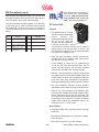
Hoppers
Bally Gaming and Systems products may use the XS1200 Standard hopper. It also may use hoppers manufactured by Asahi Seiko, Inc.
Bally XS-1200 Standard Hopper
Asahi Seiko Hopper
©2002 Bally Gaming and Systems
8-25
Peripherals
Hoppers (cont.)
NOTE: The reverse spin on the pinwheel
is slower than the forward spin, because
the CPU on the control board sends a
slower signal to prevent coins being
forced underneath the hopper knife.
Bally Gaming and Systems XS-1200
Hopper (AS-04787-SERIES)
The XS-1200 design combines operator enhancements
with the most advanced technology. It uses a multipurpose processor to provide an extremely efficient operation in a compact and simple design.
Forward / Reverse (Mixer/Motor Test): Pressing the forward switch (SW2) and the reverse switch (SW1) simultaneously will start the mixer motor, and illuminate the yellow mix LED located at CR3. The motor will remain on,
and the LED will remain lit, until either switch is released.
The primary focus of the engineering staff was to design
the most dependable increased capacity hopper for the
market and have greatly reduced the damage to components if a malfunction occurs, by adding several protective
circuits. This is further enhanced by the power
supply being included on a single printed
circuit board for quick and easy repair.
Features
• Increased capacity for all denominations of coins. The recommended running levels are 4,200
25¢, 1,000 $1 (or tokens) and 500
$5 tokens.
• Larger motor for increased power,
speed and reliability.
• Convenient switches for manual
operation and testing.
• Advanced technology for easy
repair.
• Easily adapted to various machine models.
XS-1200 Controller Board
The XS-1200 controller board is an
intelligent control circuit. It handles
all functions of the XS-1200 including pin wheel rotation, mixer rotation
and coin un-jamming routines.
Switch Descriptions and Options
Forward Switch: Pressing the forward
switch (SW2) will cause the pinwheel motor
to rotate forward (payout mode). This switch
will only function with the door open. Enabling
this switch will also illuminate the green forward
LED located at CR4. This LED will stay lit until
the switch is released.
Reverse Switch: Pressing the reverse switch (SW1)
will cause the pinwheel motor to rotate in reverse
(clear jam mode). Enabling this switch will also illuminate the red reverse LED located at CR5 until the switch
is released.
Peripherals
8-26
©2002 Bally Gaming and Systems
Peripherals
Hoppers (cont.)
ITEM
1
2
3
4
5
6
7
8
9
10
11
12
13
XS1200 HOPPER PARTS
PART #
DESCRIPTION
P-09319-0512
Bracket, Outer Mounting
P-09319-0511
Bracket, Inner Mounting
E-00733-0008
Optic Switch Assembly (2)
P-09319-0204
Bracket, Hopper Optic Guard, Outer
E-00733-0008
Optic Switch Assembly (Single)
TFPP-00632-1114 Screw
P-09319-0203
P-00845
M-03073-0002
S-00231-0978
M-03072-001B
S-02562-001A
M-03009-A001
P-00842-011B
P-00482-010B
Bracket, Hopper Optic Guard, Inner
Wiper
Wheel Housing, Hopper
Spacer
Drive Coupling, Pinwheel, Hopper
Roller Shaft
Roller (3)
Pin Wheel, 12 Pin (1.00Token)
Pin Wheel, 15 Pin (25¢)
P-00482-009B
Pin Wheel, 16 Pin (5¢)
A-04308-001A
Pin Wheel (5.00 Token)
14
15
P-00847-0024
P-00847
16
17
18
19
R-00526-0003
S-02569-0002
S-00231-0825
P-09278-0004
Spacer, Shelf Wheel (5.00 Token)
Shelf Wheel (25¢) .836” (21,23 mm) To .902”
(22,91 mm) Diameter X .062” (1,58 mm)
Width
Agitator, 5¢ to $1
Cup, Washer, Pin Wheel Hold Down
Bushing, Agitator Mounting
Bracket, Counter Balance Adjustment, Super
(mixer) Hopper
Bracket, Counter Balance Adj. Adjustment,
V 72,
Bracket, Counter Balance
P-09278-0005
P-09278-0008
NLS-25020-1112
Nut
MSOH-25020-1124
Screw
20
21
P-09277-001B
P-09263-0005
TFPP-00832-1106
Platform Bracket, (mixer)
Bracket, Hopper Mounting, Left
Screw (6)
22
P-09263-0006
TFPP-01032-1106
Bracket. Hopper Mounting, Right
Screw (6)
23
24
AS-03356-0363
P-06629-523A
TFPP_00832-1104
Hopper Control Board
Bracket, PCB
Screw (4)
LSPP-00632-1108
Screw (4)
E-00119-0532
P-00838-0011
P-00838-006B
Motor, Pinwheel, Hi-Torque, 24RPM
Outlet Cover
Outlet Cover, 5¢ & 25¢
25
26
P-00838-0009
Outlet Cover, 5¢-50¢
P-00838-007A
Outlet Cover, 1.00 Token
P-00838-005A
Outlet Cover, 5.00-100.00 Token
P-00838-0008
Outlet Cover, 5.00-100.00 Token
P-00838-0012
Outlet Cover, 5.00-100.00 Token
27
M-03068-0006
28
M-03068-0007
P-00839
P-00839-0004
Knife, Coin, Up To 1.625” (41,28mm)
Diameter
Knife, Coin, Over 1.625” (41,28mm) Diameter
Coin Deflector
Coin Deflector, 1.00, 5.00, 25.00, 100.00
Token
Screw (2)
Spacer, Deflector Plate
29
MSPF-0832-1106
P-09291-001B
XS1200 HOPPER WITH MIXER PARTS
ITEM
PART #
DESCRIPTION
1
M-03082-001A
Cover, Mixer Drive
2
P-06264-0309
Handle
TFPP-01032-1108 Screw
3
A-04349-0002
Bracket, Handle Mounting
NLS-00832-1112
Nut (2)
M-00319-0001
Stop Nut,Elastic (2)
4
P-09295-002D
Baffle
NLS-00832-112
Nut (2)
5
S-00463-0053
Pin, Level Contact (Probe)
P-00800-0006
Washer (2)
NLS-00832-112
Nut (2)
6
M-03048-0013
Coin Bowl, V7K
M-03048-0015
Coin Bowl, S6K
A-04394-0001
Grounding Stud
AS-03368-0001
Assembly, Hopper Mixer Front/Back Bracket
7
M-03047-001A
Mix Cylinder
8
M-03066-001A
Roller (4)
9
P-02891-0006
Retainer Ring
10 S-02558-001A
Shaft Roller (2)
11
TFPP-00832-1924 Screw (6)
12 M-01348-0043
Thumbscrew
13 SP-00200-0203
Spring (2)
MSPT-01032-110B Nut (2)
PW-00010-0012
Washer (2)
M-03074-001B
Adaptor
NLS-00832-0112
Nut (2)
14
MSPT-01032-1108 Screw (3)
NLS-01032-1112
Screw (3)
15 E-00119-0529
Mixer Cylinder Motor
M-03069-001B
Drive Gear Hopper
16
CPAO-01032-1804 Set Screw
S-00231-0979
Spacer (4)
17 S-00231-0978
Spacer (4)
NLS-00832-1112
Nut (2)
Rubber Grommet For Elec.Wire
18 R-00111-0029
Bracket, Drive Motor
19 P-09276-0002
20
MSPF-00832-1132 Screw
©2002 Bally Gaming and Systems
STANDARD HOPPER COIN BOWL
ITEM
PART #
DESCRIPTION
1
P-09334-002B
Handle
M-03048-0015
Coin Bowl, S6K, V8K
M-03048-0012
Coin Bowl, V7K
2
M-03048-0017
Coin Bowl, V7 Casino
M-03048-0019
Coin bowl, V72
S-00463-0053
Pin,Level Contact
3
P-09278-003A
Retaining Bracket
M-01348-0043
Thumbscrew
4
SP-00200-203
Spring (2)
8-27
Peripherals
Hoppers (cont.)
Setting the hopper probe circuit coin level
Hopper Adjustments
1. Fill the hopper with the desired number of coins. The
coins should be either level with, or slightly above,
one of the holes drilled into the side of the hopper
coin bowl.
Adjust Hopper Wiper: The wiper knocks off coins stuck
together, which allows only one coin to pass. To adjust
the wiper, follow these steps:
2. Activate the forward switch for approximately five
seconds. This will agitate, and then settle, the coins
in the bowl.
1. Turn the pin wheel to position a coin under the wiper.
2. Loosen both mounting screws and move the wiper
edge up to the coin.
3. Insert the top probe into the hole that is level with (or
just above) the amount of the coins in the bowl. This
sets the coin level for the chosen probe location.
3. Tighten both screws just enough to allow the wiper to
be moved in and out.
4. Slide a coin under the wiper edge and release it. The
coin should fall down onto the shelf wheel. The wiper
edge should be close to the coin, but not holding it.
5. Tighten the back screw, then the front screw, constantly checking the wiper position to the coin. Continue to tighten the back screw then the front until the
wiper cannot be moved in or out. Do not overtighten
the screws as the head of the screw will break off.
Adjust Hopper Knife Position: The forward edge of the
hopper knife presses against the pin wheel and touches
the edge of the shelf wheel. This allows no coin to wedge
itself between the blade and the pin.
Removing the Mix Cylinder: The mix cylinder is used to
agitate coins in the hopper to prevent coin jams. It can
be removed for hopper maintenance or replacement if
necessary.
1. Remove the gear cover.
2. There are three bolts used to secure the drive motor
to the adaptor hopper. Remove the two bolts that are
in the recessed openings, and pull the motor up and
to the side.
3. Unscrew and remove the baffle.
4. Lift out the mix cylinder.
Hopper Probe Circuit: The hopper probe circuit consists
of two hopper probes. The first probe is a stationary pin
located at the bottom of the bowl. The stationary probe
and the moveable probe are electrically connected when
the coins in the bowl are touching both probes. When
the coins in the hopper are grounding to the stationary
probe, and are also touching the moveable probe, a signal is sent to the MPU board indicating the hopper is full.
The signal triggers the diverter coil on the door so that
coins will be diverted to the drop.
Peripherals
8-28
©2002 Bally Gaming and Systems
Peripherals
• Serviceability: The DH-750/U1 was designed with the
field service industry in mind. In the event a coin jam
occurs, service techs can simply loosen the screws
to clear the jam without damaging any parts that
would otherwise require replacement. The use of
Asahi Seiko’s patented “back flow” system prevents
coins from flowing back down the escalator causing
miscounts and frequent coin jams.
Hoppers (cont.)
6644 Paradise Road, Las Vegas,
Nevada • 89119-3719 • Telephone:
(702) 260-6666 • Fax: (702) 260-6493 •
Toll Free: 1(800) 859-5353 • http://
www.asusainc.com
Asahi Seiko DH-750
Hopper, Model 53,
Slant Top (AS03105-SERIES)
General Specifications
Applicable Coin Sizes:
Diameter: 21.0mm – 38.0mm
Thickness: 1.5mm – 3.3mm
US 5¢: 1,300
Features
Coin Capacity:
US 25¢: 1,000
$1 Token: 300
•
Customization: The
DH-750/U1 allows
customers the flexibility
to design around their
requirements. They can
choose exit direction,
voltage, coin capacity,
counting method and
coin level detection as
standard options.
US 5¢: 400 coins/minute
Dispensing Speed:
US 25¢: 380 coins/minute
US $1: 200 coins/minute
DH-750 Hopper
Coin Counting Method:
Proximity Sensor or Microswitch
Motor Voltage:
115VAC, 220VAC, 24VDC (Thermal Protector and
Instant Stop device included on AC motors only)
Motor Rating:
5 Minutes
Current Consumption:
3.0A @ 115V AC
Operation Temperature:
-10°C - +60°C
Weight:
14.69 pounds approx. (AC motor)
DH-750 Model 53 Hopper Assembly
©2002 Bally Gaming and Systems
8-29
Peripherals
Hoppers (cont.)
Item#
1
2
3
4
5
6
7
8
9
10
11
12
13
14:
15
16
17
18
19
20
21
22
23
24
25
26
27
28
29
30
31
Bally Part #
ASH-05000-0005
ASH-05000-0040
ASH-05000-0097
ASH-05000-0168
ASH-05000-0094
ASH-05000-0044
ASH-05000-0169
ASH-05000-0095
ASH-05000-0045
ASH-05000-0077
ASH-05000-0096
ASH-05000-0043
ASH-05000-0006
ASH-05000-0007
ASH-05000-0008
ASH-05000-0112
ASH-05000-0113
ASH-05000-0106
ASH-05000-0086
ASH-05000-0002
ASH-05000-0009
ASH-05000-0034
ASH-05000-0010
ASH-05000-0011
ASH-05000-0099
Asahi Seiko Part #
DH7991M025001
DH7534M025002
DH7534M025003
DH7534M025004
W4000SW99
S4006RHSW
DH7001M025007
DH7004M025008
DH7001M025055
DH7101M025536
DH7101M005530
DH7101M025530
DH7101M10T530
DH7101M005531
DH7101M025531
DH7101M10T531
DH7534M025529
DH7101M025534
DH7101M025015
DH7001M025016
DH7001M025017
DH7001M025018
W3000ER99
N4000HX99
B4012HX99
W3008FW08
S3010RH99
N3000HX99
DH7001M005025
DH7001M025025
DH7001M10T025
DH7001M025026
DH7001M025027
DH7101M10T538
DH7101M025538
S4012HXSS
S4025HXSS
NOTE: Items without a Bally part number
are not stocked by Bally.
DH-750 MODEL 53, SLANT TOP
Description
Item#
PLATE, CHASSIS
32
FRAME, SIDE (R)
33
FRAME, SIDE (L)
PLATE. BASE
WASHER, M4 SPLIT
34
SCREW, M4x6 W/SW
35
PIN, MOTOR DRIVE
36
MOTOR, 24VDC (DME44S7C-272)
37
HANDLE
38
BRACKET, ESCALATOR MOUNTING
39
GUIDE, TRANSITION (R), US 5¢
40
GUIDE, TRANSITION (R), US 25¢
41
GUIDE, TRANSITION (R). $1 TOKEN
42
GUIDE, TRANSITION (L). US 5¢
43
GUIDE, TRANSITION (L), US 25¢
GUIDE, TRANSITION (L), $1 TOKEN
44
COVER, TRANSITION (R)
45
PLATE, COIN SLIDE
46
ROLLER LEVER, ESCALATOR
47
SPRING. ROLLER LEVER
48
PIN, ROLLER LEVER
49
BEARING, ROLLER LEVER
50
03 E-RING
51
NUT, M4
52
BOLT, M4x12
53
WASHER, 3x8x0.8 FLAT
54
SCREW, M3x10
NUT, M3
KNIFE, US 5¢
55
KNIFE, US 25¢
KNIFE, $1 TOKEN
BOSS. PLASTIC
56
SCREW. BEVEL-HEADED
COVER, TRANSITION (L) $1T
57
COVER, TRANSITION (L)
SCREW, M4x12 UPSET SF SS
58
SCREW, M4x25 UPSET SF SS
COIN HOPPER
Bally Part #
ASH-05000-0001
ASH-05000-0003
ASH-05000-0012
ASH-05000-0035
ASH-05000-0013
ASH-05000-0014
ASH-05000-0015
ASH-05000-0016
ASH-05000-0170
ASH-05000-0108
ASH-05000-0029
ASH-05000-0030
ASH-05000-0037
ASH-05000-0022
ASH-05000-0026
ASH-05000-0027
ASH-05000-0036
ASH-05000-0004
ASH-05000-0028
Asahi Seiko Part #
B4025HXSS
DH7001M005033
DH7001M025033
DH7001M10T033
DH7001M025034
DH7001M025035
DH7001M025036
DH7001M025037
W4015FW10
S4008LHSS
S 4015C S 99
W4010FW10
DH7001M025073
DH7001M025074
DH7001M10T074
S4010HXSS
S4015HXSS
S3010HXSS
S4012HXSS
S4008HXSW
DH7001M025057
DH7001M025058
DH7001M025059
DH7001M025064
S4025LHSS
DH7001M005070
DH7001M025070
DH7001M10T070
DH7001M005071
DH7001M025071
DH7001M10T071
DH7001M005072
DH7001M025072
DH7514M025650
DH7514M10T650
S4020HXSS
Description
BOLT, M4x25, SS
DISC, US 5¢
DISC. US 25¢
DISC. $1 TOKEN
SPRING, STIRRING
COVER, SPRING
HOLDER. SPRING
SPRING, DISC
WASHER, 4x15x1.0 FLAT
SCREW. M4x8 TRUSS HEAD SS
SCREW, M4x15 COUNTERSUNK
WASHER, 4x10x1.0 FLAT
SEPARATOR, COIN
RETAINER, SEPARATOR
RETAINER, SEPARATOR. $1 TOKEN
SCREW, M4x10 UPSET SF SS
SCREW, M4x15 UPSET SF SS
SCREW, M3x10 UPSET SF SS
SCREW, M4x12 UPSET SF SS
SCREW, M4x8 UPSET SW SS
CAST FRAME
06 BALL BEARING
RETAINER, BEARING
WASHER, ROLLER LEVER
SCREW, M4x25 LARGE HEAD SS
PLATE, ADJUSTING, US 5¢
PLATE, ADJUSTING, US 25¢
PLATE, ADJUSTING, $1 TOKEN
RUBBER, JUMP, US 5¢
RUBBER, JUMP, US 25¢
RUBBER, JUMP. $1 TOKEN
COVER. JUMP, US 5¢
COVER, JUMP
SHIM, TRANSITION (L) O.3t
SHIM, TRANSITION (L) 0.5t
SCREW, M4x20 UPSET SF SS
DH-750 Model 53, Slant Top Bowl Assembly
Peripherals
8-30
©2002 Bally Gaming and Systems
Peripherals
Hoppers (cont.)
Item#
Bally Part #
1
2
3
4
5
6
7
8
9
10
11
12
ASH-05000-0108
13
ASH-05000-0109
14
15
Asahi Seiko Part #
DH7031M025322
DH7534M025950
DH7031M025046
DH7011M025153
DH7011M025093
W5000SR99
N5000SN99
W5012FVW08
M4000HX99
W4000SW99
W4015FW10
S 4015C S 99
S4015LHSS
DH7011M025307
W4000SR99
NOTE: Items without a Bally part number
are not stocked by Bally.
DH-750 MODEL 53, SLANT TOP
Description
SCOOP. ALUMINUM
BOWL, HOPPER (PLASTIC)
PLATE, REGULATOR
.PROBE PIN
05 WIRE TERMINAL
WASHER, M5,STAR
NUT.M5 SHOULDER
WASHER, 5x12X0.8 FLAT
NUT, M4
WASHER, M4 SPLIT
WASHER, 4x15x1.0 FLAT
SCREW, M4X15 COUNTERSUNK
SCREW, M4x15 LARGE HEAD SS
04 WIRE TERMINAL
WASHER. M4 STAR
BOWL
Item#
16
17
18
19
20
21
22
23
24
25
26
27
28
29
30
ASSEMBLY (PLASTIC)
Bally Part #
Asahi Seiko Part #
N4000SN99
S4012LH99
ASH-05000-0021 DH7001M025052
S3010LH99
ASH-05000-0113 W3008FW05
W3000SW99
ASH-05000-0086 N3000HX99
ASH-05000-0018 DH7001M025047
ASH-05000-0019 DH7001M025048
ASH-05000-0020 DH7001M025049
ASH-05000-0104 N4006HX99
ASH-05000-0038 DH7001M10T081
S4008RHSF
DH7031M025324
DH7534M025325
Description
NUT, M4 SHOULDER
SCREW. M4x12 LARGE HEAD
INSULATOR
SCREW. M3x10 LARGE HEAD
WASHER, 3x8x0.5 FLAT
WASHER. M3 SPLIT
NUT, M3
SCREW, BOWL MOUNTING
SPRIN6. BOWL MOUNTING, UPPER
SPRING, BOWL MOUNTING, LOWER
NUT, M4 SMALL
COLLAR. SPACING ($1 TOKEN ONLY)
SCREW, M4x8 W/SW & FW
ROLLER, SUPPORT
BRACKET, SUPPORT
DH-750 Model 53, Slant Top Escalator Assembly
©2002 Bally Gaming and Systems
8-31
Peripherals
Hoppers (cont.)
Item#
1
2
3
4
5
6
7
8
9
10
11
12
Bally Part #
ASH-05000-0020
ASH-05000-0111
ASH-05000-0088
ASH-05000-0089
ASH-05000-0140
ASH-05000-0039
ASH-05000-0086
13
ASH-05000-0047
ASH-05000-0052
Asahi Seiko Part #
DH7101M025516
S3010HXSW
S3012HXSW
W2000ER99
DH7101M025522
DH7101M025523
S3013RH99
DH7534M025068
DH7001P025013
N3000HX99
DH7301M025069
S3016RH99
DH7534M005601
DH7534M025601
DH7534M10T601
DH7301M005507
DH7301M025507
DH7301M10T507
NOTE: Items without a Bally part number
are not stocked by Bally.
DH-750 MODEL 53, SLANT TOP ESCALATOR ASSEMBLY
Description
Item#
Bally Part #
Asahi Seiko Part #
PLATE, ACTUATOR MOUNTING
14
DH7534M005604
SCREW, M3x10 UPSET SW SS
DH7534M025604
SCREW, M3x12 UPSET SW SS
DH7534M10T604
02 E-RING
15
DH7534M025606
ACTUATOR, M/S INBOARD
16
ASH-05000-0160 DH7301M005560
SPRING, ACTUATOR
ASH-05000-0049 DH7301M025560
SCREW, M3x13
17
DH7534M005605
MICROSWITCH (D44L-R1LD)
DH7534M025605
PROXIMITY SENSOR
DH7534M025605
NUT, M3
18
DH7534M025607
BRACKET. M/S MOUNTING (INBOARD)
19
S3010HXSS
SCREW, M3x16
20
ASH-05000-0091 DH7101M025525
PLATE, BACK US 5¢
21
ASH-05000-0090 DH7101M025524
PLATE, BACK US 25¢
22
ASH-05000-0092 DH7101M025527
PLATE, BACK $1T
23
S3012HXSS
GUIDE, TOP (L) US 5¢
24
ASH-05000-0079 DH7534M025565
GUIDE. TOP (L) US 25¢
25
DH7534M025602
GUIDE. TOP (L) $1T
26
ASH-05000-0048 DH7301M025514
Description
RAIL. GUIDE (L) 2.5t
RAIL. GUIDE (L) 2.Ot
RAIL, GUIDE (L) 3.2t
COVER. GUIDE (L)
GUIDE, TOP (R) US 5¢
GUIDE, TOP (R) US 25¢
RAIL. GUIDE (L) 2.5t
RAIL, GUIDE (L) 2.0t
RAIL, GUIDE (L) 3.2t
COVER. GUIDE (R)
SCREW, M3x10 UPSET SF SS
011 BALL BEARING
RETAINER, CHECK BALL
BOLT, M4x1OWING
SCREW, M3x12 UPSET SF SS
SUPPORT, ESCALATOR
RAIL SPACER
COVER, TOP
DH-750 Model 51 Hopper Assembly
Peripherals
8-32
©2002 Bally Gaming and Systems
Peripherals
Hoppers (cont.)
Item#
1
2
3
4
5
6
7
8
9
10
11
12
13
14
15
16
17
18
19
20
21
22
23
24
25
26
27
28
29
30
31
32
33
Bally Part #
ASH-05000-0005
ASH-05000-0040
ASH-05000-0097
ASH-05000-0168
ASH-05000-0044
ASH-05000-0169
ASH-05000-0045
ASH-05000-0077
ASH-05000-0096
ASH-05000-0006
ASH-05000-0007
ASH-05000-0008
ASH-05000-0112
ASH-05000-0113
ASH-05000-0106
ASH-05000-0086
ASH-05000-0002
ASH-05000-0009
ASH-05000-0034
ASH-05000-0010
ASH-05000-0011
ASH-05000-0099
ASH-05000-0001
ASH-05000-0003
ASH-05000-0012
ASH-05000-0035
Asahi Seiko Part #
DH7991M025001
DH7534M025002
DH7514M025003
DH7534M025004
W4000SW99
S4006RHSW
DH7001M025007
DH7004M025008
DH7001M025055
DH7101M025536
DH7101M005530
DH7101M025530
DH7101M10T530
DH7101M005531
DH7101M025531
DH7101M10T531
DH7534M025529
DH7101M025534
DH7514M025918
DH7001M025016
DH7001M025017
DH7001M025018
W3000ER99
N4000HX99
B4012HX99
W3008FW08
S3010RH99
N3000HX99
DH7001M005025
DH7001M025025
DH7001M10T025
DH7001M025026
DH7001M025027
DH7101M10T538
DH7101M025538
S4012HXSS
S4025HXSS
B4025HXSS
DH7001M005033
DH7001M025033
DH7001M10T033
NOTE: Items without a Bally part number
are not stocked by Bally.
DH-750 MODEL 51, BARTOP (AS-03107-SERIES)
Description
Item#
Bally Part #
PLATE, CHASSIS
34
ASH-05000-0013
FRAME, SIDE (R
35
ASH-05000-0014
FRAME, SIDE (L
36
ASH-05000-0015
PLATE. BASE
37
ASH-05000-0016
WASHER, M4 SPLIT
38
SCREW, M4x6 W/SW
39
ASH-05000-0170
PIN, MOTOR DRIVE
40
ASH-05000-0108
MOTOR, 24VDC (DME44S7C-272)
41
HANDLE
42
ASH-05000-0029
BRACKET, ESCALATOR MOUNTING
43
ASH-05000-0030
GUIDE, TRANSITION (R), US 5¢
ASH-05000-0037
GUIDE. TRANSITION (R), US 25¢
44
GUIDE. TRANSITION (R). $1 TOKEN
45
GUIDE, TRANSITION (L), US 5¢
46
GUIDE, TRANSITION (L), US 25¢
47
GUIDE, TRANSITION (L), $1 TOKEN
48
COVER, TRANSITION (R)
49
ASH-05000-0022
PLATE, COIN SLIDE
50
LEVER, ROLLER
51
SPRING, ROLLER LEVER
52
PIN, ROLLER LEVER
53
BEARING, ROLLER LEVER
54
03 E-RING
ASH-05000-0026
NUT, M4
BOLT, M4x12
55
WASHER, 3x8x0,8 FLAT
ASH-05000-0027
SCREW, M3x10
ASH-05000-0036
NUT, M3
56
ASH-05000-0004
KNIFE, US 5¢
ASH-05000-0028
KNIFE. US 25¢
57
KNIFE, $1 TOKEN
BOSS, PLASTIC
58
SCREW, BEVEL-HEADED
59
COVER, TRANSITION (L) $1T
60
COVER, TRANSITION (L)
61
SCREW, M4x12 UPSET SF SS
62
SCREW, M4x25 UPSET SF SS
63
BOLT. M4x25, SS
64
DISC, US 5¢
65
DISC, US 25¢
DISC, $1 TOKEN
Asahi Seiko Part #
DH7001M025034
DH7001M025035
DH7001M025036
DH7001M025037
W4015FW10
S4008LHSS
S 4015C S 99
W4010FW10
DH7001M025073
DH7001M025074
DH7001M10T074
S4010HXSS
S4014HXSS
S3010HXSS
S4012HXSS
S4008HXSW
DH7001M025057
DH7001M025058
DH7001M025059
DH7001M025064
S4025LHSS
DH7001M005070
DH7001M025070
DH7001M10T070
DH7001M005071
DH7001M025071
DH7001M10T071
DH7001M005072
DH7001M025072
DH7514M025650
DH7514M10T650
DH7514M025915
DH7514M025916
DH7514M025917
DH7514M025920
N3000LN99
S3005RHSF
S3595TP99
S4020HXSS
Description
SPRING, STIRRING
COVER, SPRING
HOLDER, SPRING
SPRING, DISC
WASHER, 4x15x1.0 FLAT
SCREW. M4x8 TRUSS HEAD SS
SCREW. M4x15 COUNTERSUNK
WASHER, 4x10x1.0 FLAT (US 5¢ ONLY)
SEPARATOR, COIN
RETAINER, SEPARATOR
RETAINER, SEPARATOR. $1 TOKEN
SCREW, M4x10 UPSET SF SS
SCREW. M4x14 UPSET SF SS
SCREW, M3x10 UPSET SF SS
SCREW, M4x12 UPSET SF SS
SCREW, M4x8 UPSET SW SS
CAST FRAME
06 BALL BEARING
RETAINER, BEARING
WASHER, ROLLER LEVER
SCREW, M4x25 LARGE HEAD. SS
PLATE, ADJUSTING, US 5¢
PLATE, ADJUSTING, US 25¢
PLATE, ADJUSTING, $1 TOKEN
RUBBER, JUMP, US 5¢
RUBBER, JUMP, US 25¢
RUBBER, JUMP. $1 TOKEN
COVER. JUMP, US 5¢
COVER, JUMP
SHIM, TRANSITION (L) O.3t
SHIM, TRANSITION (L) 0.5t
BRACKET, OPTIC MOUNTING
FLAG, OPTIC
COVER, OPTIC
OPTIC
NUT, M3 NYLON LOCK
SCREW, M3x5 W/SW & FW
SCREW, M3.5x9.5 TAPPING
SCREW, M4x20 UPSET SF SS
DH-750 Model 51, Bartop Bowl Assembly
©2002 Bally Gaming and Systems
8-33
Peripherals
Hoppers (cont.)
Item#
Bally Part #
1
2
3
4
5
6
7
8
9
10
11
12
13
ASH-05000-0108
14
ASH-05000-0109
15
16
Asahi Seiko Part #
DH7031M025322
DH7514M025050
S4008RHSF
DH7031M025046
DH7011M025153
DH7011M025093
W5000SR99
N5000SN99
W5012PW08
N4000HX99
W4000SW99
W4015FW10
S 4015C S 99
S4015LHSS
DH7011M025307
W4000SR99
NOTE: Items without a Bally part number
are not stocked by Bally.
DH-750 MODEL 51, BARTOP BOWL ASSEMBLY
Description
Item#
Bally Part #
SCOOP. ALUMINUM
17
BOWL, HOPPER
18
SCREW, M4x8 W/SW & FW
19
ASH-05000-0021
PLATE, REGULATOR
20
PROBE PIN
21
ASH-05000-0113
05 WIRE TERMINAL
22
WASHER, M5 STAR
23
ASH-05000-0086
NUT. M5 SHOULDER
24
ASH-05000-0018
WASHER, 5x12x0.8 FLAT
25
ASH-05000-0019
NUT, M4
26
ASH-05000-0020
WASHER, M4 SPLIT
27
ASH-05000-0104
WASHER, 4x15x1.0 FLAT
28
ASH-05000-0038
SCREW. M4x15 COUNTERSUNK
29
SCREW, M4x15 LARGE HEAD SS
30
04 WIRE TERMINAL
31
WASHER, M4 STAR
Asahi Seiko Part #
N4000SN99
S4010LH99
DH7001M025052
S3010LH99
W3008FW05
W3000SW99
N3000HX99
DH7001M025047
DH7001M025048
DH7001M025049
N4006HX99
DH7001M10T081
W4010FW16
DH7031M025324
DH7534M025325
Description
NUT, M4 SHOULDER
SCREW, M4x1O LARGE HEAD
INSULATOR
SCREW. M3x10 LARGE HEAD
WASHER, 3x8x0.5 FLAT
WASHER, M3 SPLIT
NUT, M3
SCREW, BOWL MOUNTING
SPRING, BOWL MOUNTING, UPPER
SPRING, BOWL MOUNTING, LOWER
NUT, M4 SMALL
COLLAR, SPACING ($1 TOKEN ONLY)
WASHER, 4x10x1.6 FLAT (5^ ONLY)
ROLLER. SUPPORT
BRACKET, BOWL SUPPORT
DH-750 Model 51, Bartop Escalator Assembly
Peripherals
8-34
©2002 Bally Gaming and Systems
Peripherals
Hoppers (cont.)
Item#
I
Bally Part #
2
ASH-05000-0047
ASH-05000-0052
3
4
5
6
7
ASH-05000-0049
ASH-05000-0146
ASH-05000-0147
ASH-05000-0149
ASH-05000-0150
ASH-05000-0151
ASH-05000-0152
ASH-05000-0153
NOTE: Items without a Bally part number
are not stocked by Bally.
Asahi Seiko Part #
DH7514M005505
DH7514M025505
DH7514M10T505
DH7301M005507
DH7301M025507
DH7301M10T507
DH7301M005560
DH7301M025560
DH7514M005506
DH7514M025506
DH7514M10T506
DH7514M005508
DH7514M025508
DH7514M10T508
DH7514M025509
DH7514M025511
DH-750 MODEL 51, BARTOP ESCALATOR ASSEMBLY
Description
Item#
Bally Part #
Asahi Seiko Part #
PLATE, BACK, US 5¢
8
ASH-05000-0048 DH7301M025514
PLATE, BACK, US 25¢
9
DH7101M025524
PLATE. BACK, $1 TOKEN
10
DH7101M025525
GUIDE. 1 UP (L), US 5¢
11
S3012HXSS
GUIDE, TOP (L), US 25¢
12
S3012HXSS
GUIDE, TOP (L). $1 TOKEN
13
S3010HXSS
GUIDE, TOP (R). US 5¢
14
DH7101M025527
GUIDE, TOP (R), US 25¢
15
ASH-05000-0086 N3000HX99
RAIL, GUIDE (L), US 5¢
16
DH7101M025516
RAIL, GUIDE (L). US 25¢
17
ASH-05000-0025 DH7001M025069
RAIL. GUIDE (L), $1 TOKEN
18
S3016RH99
RAIL, GUIDE (R), US 5¢
19
S3010HXSW
RAIL, GUIDE (R), US 25¢
20
S3012HXSW
RAIL, GUIDE (R). $1 TOKEN
21
DH7301M025522
COVER, GUIDE (L)
22
DH7101M025523
COVER, GUIDE (R)
23
ASH-05000-0111 W2000ER99
PROBE AT
LE V E L
1
2
3
4
5
6
PROBE AT
LE V E L
1
2
3
4
5
6
PROBE AT
LE V E L
1
2
3
4
5
6
©2002 Bally Gaming and Systems
HOPPER CAPACITIES
STANDARD
SUPER
VIDEO
SLOT
VIDEO
5¢
1100
700
2100
2100
1000
2900
3100
1700
3600
2200
4300
2800
5000
3400
STANDARD
SUPER
VIDEO
SLOT
VIDEO
25¢
900
700
1600
1000
2200
1500
1400
2800
2200
1700
3400
3100
2400
4000
3800
2900
4200
STANDARD
SUPER
VIDEO
SLOT
VIDEO
$1
340
140
500
560
280
640
800
400
800
560
900
680
1100
820
8-35
SLOT
1200
2000
2500
3400
3800
4300
SLOT
Description
COVER, TOP
BRACKET. BALL RETAINING
011 BALL BEARING
SCREW, M3x12 UPSET SF SS
SCREW. M3x12 UPSET SF SS
SCREW, M3x1O UPSET SF SS
BOLT, M4 WING
NUT, M3
PLATE, ACTUATOR MOUNTING
PLATE, M/S MOUNTING, INBOARD
SCREW, M3x16
SCREW, M3x1O UPSET SWSS
SCREW, M3x12 UPSET SW SS
ACTUATOR, M/S, INBOARD
SPRING, ACTUATOR
02 E-RING
ASAHI-SEIKO
5000
ASAHI-SEIKO
1000
3500
SLOT
300
460
660
800
1000
1200
ASAHI-SEIKO
1200
Peripherals
Ticket Printers
Power Requirements
TransAct Technologies, Inc. •
20 Bomax Drive Ithaca, New
York 14850 USA • Phone:
Sales/Support 1-877-7ithaca
or (607)-257-8901 Fax: Sales (607) 257-3868 / Support
(607) 257-3911 • http://www.ithper.com
• Standard (Internal Supply): 110/120 VAC, 60 Hz
• Optional (Internal Supply): 220/240 VAC, 50/60 Hz
Reliability
• Printer in full operation (using all available features)*
Ithaca Series 70 Impact
Ticket Printer
• MTBF: 25,000 Hours
• Printhead: 200,000,000 Characters
The Series 70 takes the gamble out
of consistent, quality impact printing
for unattended printing applications.
The Series 70 delivers receipts, tickets, and coupons at 4.9 lines per second with solid consistency. It features
enhanced or emphasized font styles
Series 70
for greater legibility, and utilizes Oki®
technology, known worldwide for quality, reliability, and snap-in/snap-out, user-friendly ribbon
cassette. The Series 70 has a convenient “Paper Low”
indicator to alert you before the paper roll runs out.
• Auto-Cutter: 1,000,000 Cuts
Reliability data is based on Ithaca standard test conditions.
Environmental Specifications
• Operating Temperature: 0 to +50 degrees C (32 to
+122 degrees F)
• Operating Humidity: 10 to 90% RH non-condensing
Media
Features
• Standard Paper Roll—M75 (one-ply):
• All Printers are Mechanisms with Drive Electronics
Width: 82.5 mm (3.25 in.) Diameter: 89.0 mm (3.5
in.) or optional 152.0 mm (6 in.)
• Print Speed: 4.9 lps.—On Standard Test Receipt
One-ply Maximum Thickness: .11 mm (.0045 in.)
• One-Year Standard Warranty: Extended Maintenance
Plan Available
Length Per Roll (3.5 in. dia.): 74.6 m (245 ft.)
• Data Buffer: 2K
Length Per Roll (6 in. dia.): 148.8 m (488 ft.)
• Standard Paper Roll—M76 (two-ply):
• Auto-Cutter (Full Cut): 82.5 mm (3.25 in.)
Width: 82.5 mm (3.25 in.) Diameter: 89.0 mm (3.5
in.) Maximum Thickness Per Ply: .09 mm (.0035 in.)
• CPI: 5, 6, 8.5, 10, 12, 15, 17.1, 24
• Print Zone: 60 mm (2.34 in.)
Length Per Roll: 38.1 mm (125 ft.)
• Self-Test: Test Ticket
• Ribbons: 3-4.5 Million Character Life
• Low 37W Power
Ithaca or Genuine Oki Snap-on Ribbon Cassette
(Black or Purple)
• Paper Low Indicator
Physical Characteristics
• Character Sets: 2 ASCII (slashed ø and unslashed
• Dimensions (without transport): 154 mm H x 274 mm
0), IBM Character Sets I and II, French, French Canadian, Spanish, German
L x 172 mm H (6.06 in. W x 10.75 in. L x 6.75 in. H)
• Barcodes: Code 128, Interleaved 2 of 5, Interleaved
• Weight: 3.86 kg (8.5 lbs.)
3 of 9
Peripherals
8-36
©2002 Bally Gaming and Systems
Peripherals
1. To remove the old cassette slide the Printhead Carriage Assembly to the middle.
Ticket Printers (cont.)
Connection Printer (Centronics)
2. Hold down the Cutter Blade Cover.
1
BK/RD
Strobe
19
2
BR
Data 1
20
3
WT
Data 2
21
4
OR/BL
Data 3
22
5
YE
Data 4
23
6
OR
Data 5
24
7
GY
Data 6
25
8
BL
Data 7
26
9
YE/WT
Data 8
27
WT/BL
Busy
29
10
11
3. Grasp the bottom of the ribbon cassette and pull out.
28
12
WT/BR
Paper End
30
13
WT/OR
Select
31
BR/BK
Printer Reset
14
32
WT/BK
Printer Fault
15
33
BK
Ground
16
BK
Ground
34
17
35
18
36
Backplane (Dual Row Header)
1
BR
Data 1
14
2
WT/OR Select
15
3
4
5
6
7
8
9
10
11
12
13
WT
WT/BL
OR/BL
16
17
18
19
20
21
22
23
24
25
26
Data 2
Busy
Data 3
YE
BK-1
OR
BK-2
GY
Data 4
Ground
Data 5
Ground
Data 6
BL
Data 7
YE/WT
Data 8
BK/RD
Strobe
BR/BK
Printer Reset
WT/BK
Printer Fault
4. To install the new cassette hold down the Cutter
Blade Cover.
5. Align the grooves at the top of the cassette with the
tabs on the Printhead Carriage Assembly.
6. Pivot the ribbon cassette into the Printhead Carriage Assembly until it snaps into place.
WT/BR Paper End
7. Tighten the ribbon by turning the knob on the
cassette clockwise.
Changing the Ribbon Cassette: Change the cassette
when the print becomes faded. Worn ribbons can damage the print head.
©2002 Bally Gaming and Systems
8-37
Peripherals
2. Remove the spindle from the journal by unscrewing
the left flange in the direction of the OFF arrow. Secure and store the journal roll as required.
Ticket Printers (cont.)
Ordering Supplies
The following parts are available through TransAct Technologies, Inc.:
Description
Paper (two-ply)
Ribbon Cassette (black or dark purple)
Supply Roll Spindle Large Diameter
Supply Roll Spindle Small Diameter
Take-up Spindle Take-up Core
Take-up Flange
Take-up Assembly (both core and flange)
Power Cord
Fuses 1.0 Amp, 125 Volt
1.5 Amp, 125 Volt
Printhead
Printhead Clamp
Part #
98-0558
06-0560 (case of 12)
09-1230
09-1494
06-0597
06-0599
06-0993
06-0561
150-9810010
150-9810015
06-0565
06-0571
3. Unsnap the Supply Roll Spindle from the bracket. Hold
down the Cutter Blade Cover and pull the remaining
paper out of the printer.
Changing Paper
Change the Supply Roll paper when you see the pink
stripe on the receipt paper or when the terminal indicates the paper is low. Although the pink stripe appears
with eight to ten feet left on the roll, the printer will print
only 21 inches after the Paper Low sensor activates.
4. Remove the spindle from the used supply roll and
set it aside. Don’t throw it away.
1. Unsnap the Journal Takeup Roll Spindle from the
bracket. Tear off the yellow journal paper using the
Shear Plate.
5. Trim enough of the new Supply Roll for a straight edge
free from glue.
6. Put the spindle that was removed from the used supply roll into the new roll so that the white receipt paper is on the outside (See figure below). Snap the
spindle into the lower set of snaps in the Bucket.
7. Hold down the Cuter Blade Cover and push the paper up through the throat in the back of the Bucket
until the paper passes the printhead.
Peripherals
8-38
©2002 Bally Gaming and Systems
Peripherals
12. Turn the Journal Takeup Spindle a few turns in the
direction of the ON arrow to take up the excess journal paper.
Ticket Printers (cont.)
8. The receipt and journal thread through different paths.
Using the Thumb Wheel ( Gear on the left side. See
bottom figure) to advance the paper, guide the journal
and receipt paper so that they are separated by the
Shear Plate.
Function Switch
The Function Switch is
a momentary two-position switch that provides
the following functions:
With power ON:
Left: Incremental paper
advance
Right: Auto paper advance and cut.
Position switch with
power OFF, then power ON:
9. Advance about six inches of paper then tear off only
the white receipt ply.
Left: Print Test
Right: Hex Data Dump
Replacing the Printhead
WARNING: The printhead may be hot.
1. Remove the ribbon cassette.
2. Release the printhead by unfastening the Printhead
Clamp. Pull the tab on the left to swing it open.
10. Reassemble the Journal Takeup Spindle by turning
the flange in the direction of the ON arrow. Do not
overtighten.
3. Hold down the Cutter Blade Cover.
4. Pull the printhead free from the edge connecter and
carriage.
11. Fold about ½” of the journal paper and insert it into
the groove of the Journal Takeup Spindle so that the
gear is to the right.
©2002 Bally Gaming and Systems
5. Using the guide on the printhead, slide the new
printhead onto the carriage and into the edge connector.
8-39
Peripherals
Ticket Printers (cont.)
Ithaca Series 700 Thermal
6. Secure the printhead with the Printhead Clamp.
Ticket Printer
7. Put the ribbon cassette back in.
Coin-free slot machines have
never been so hassle-free.
With the Series 700, the
ticket will not stick out until it
is completely printed. This
Series 700
prevents players from pulling
it too soon—a major cause of printer problems. Another
practical features is a user-friendly, illuminated front bezel; a ticket supply box that holds 400 tickets; and a ballbearing drawer chassis that slides out for easy ticket
loading and maintenance.
Features
• Print Resolution: 8 dots per mm (203dpi) Horizontal
and Vertical
8. Check the print quality. Use the blue lever on the side
of the carriage for lighter or darker printing.
• Easy Ticket Loading
• Print Zone Width: 56 mm (2.205 in.)
• Data Buffer: 4K
• Memory: 64K EPROM & 32K RAM
• Self Diagnostics
• Standard Warranty: 1 year
• Bar Code: Code 3 of 9, Interleaved 2 of 5, UPC-A &
UPC-E, Codabar,
• EAN8 and EAN13, Code 128, and Postnet
• Ticket Low Sensor
• Top of Form/Ticket-Out Sensor
• High Quality Printing: Text, Barcodes, Graphics, Lines
Bitmap Graphics, Portrait, and Landscape Printing
• Ticket is contained within the printer until printing is
complete, preventing user interference.
Printing Characteristics
• Print Speed: 51 mm/sec (2 in. per second)
• Five Fonts: 7.5 cpi, 10 cpi, 12 cpi, 16.5 cpi, and 20 cpi
• Normal, Double-high, Double-wide, and Double-high/
Double-wide print modes
• Prints on 62 mm x 120 mm, 65 mm x 120 mm, 65 mm
x 156 mm (dollar-bill size) tickets
NOTE: 65 mm x 156 mm ticket requires no printing on last 1.4 inches
of each ticket
Peripherals
8-40
©2002 Bally Gaming and Systems
Peripherals
green test LED, located on the top of the “Core” printer,
should be on when the printer is correctly receiving
power. After confirming that the printer is receiving power,
check to see that the ticket has been loaded correctly
and is not jammed in the ticket path. Pressing the Ticket
Feed switch-on the top of the “Core” printer-will advance
a single ticket through the print mechanism, automatically positioning the tickets correctly. Check all connections to ensure a proper signal.
Ticket Printers (cont.)
Physical Characteristics
• 750—139 mm W x 85 mm H x 159 mm D (5.46 in. W
x 3.36 in. H x 6.27 in. D)
• Overall Size with All Options (with 120 mm length
ticket supply box):
139 mm W x 85 mm H x 287 mm D (5.46 in. W x 3.36
in. H x 11.29 in. D)
If the printer does not stop feeding when it automatically
scrolls the ticket, check to see that the tickets are facing
the right direction so the ticket present sensor detects
the Black Dot/Top of Form indicator.
Weight: 3.31 kg (7.30 lbs.)
• Overall Size with All Options (with 156 mm length
Loading Tickets into the Feeding Mechanism: The first
ticket of the stack must be inserted into the printer by hand.
With the Series 700 Printer Ticket Supply Box, there is a
guide to direct the ticket into the printer mechanism. To
load the printer, grasp the first ticket, and insert it into the
guide until the ticket reaches the printer mechanism. Continue pushing gently until the printer mechanism detects
the ticket and the motor pulls it through the printer. The
printer will stop feeding automatically. Pressing the Ticket
Feed button on the printer controller board will run the
motor to present blank tickets or to aid in loading.
ticket supply box):
139 mm W x 85 mm H x 325 mm D (5.46 in. W x 3.36
in. H x 12.8 in. D)
Weight: 3.41 kg (7.50 lbs.)
Media (Thermal Ticket, Fan Fold, Perforated)
• Type: Top coated, high sensitivity, direct thermal
(Kanzaki TO-381N or approved equivalent)
• Thickness: 0.112 mm (0.0044 in.)
1. Insert the first ticket, blank side up, into the ticket feed
guides as shown by the load ticket arrow on the instruction card.
• Width x Length: 62 mm (2.44 in.) x 120 mm (4.73 in.);
65 mm (2.56 in.) x 120 mm (4.73 in.); 65 mm (2.56
in.) x 156 mm (6.14 in.) dollar-bill size
2. The printer will automatically feed the ticket when the
ticket is sensed by the printer.
• Standard Store: 400 tickets per stack
Interface
• Bi-Directional RS232C
3. If ticket does not feed automatically, press the Ticket
Feed switch.
• CTS and/or XON/XOFF Handshake
4. Remove the excess ticket from the front of the printer.
Power Requirements
• 24VDC: 1.5A (supplied by system)
• Exit Lamp: 13VDC @ 150mA (supplied by system)
Reliability: Printhead Life: 25 km
Environmental Specs
• Operating Temperature: 0C to + 40C
• Storage Temperature: -20C to + 70C
• Operating Humidity: 5 to 95% RH Non-Condensing
Troubleshooting
If the 700 Series printer is experiencing printing problems, check to see if the unit is receiving power. The
©2002 Bally Gaming and Systems
8-41
Peripherals
Ticket Printers (cont.)
Seiko Instruments USA Inc. •
Micro Printer Division • 2990
West Lomita Blvd., Torrance, CA
90505 • Phone: (800) 553-6570
Fax: (310) 517-8154 • www.seikoprinters.com
PSA-66 Thermal Ticket
Printer
Place paper stack in Paper Tray
Operator Interface: The
printer has status indicators
and two controls. The
PSA-66-ST
status indicators are part of
the Keypad. They are LEDs labeled STATUS and
ERROR. The Operator controls are the Keypad and the
Platen Release Lever.
INSERT PAPER HERE
Loading Paper
Paper Orientation Label
To load paper, pull open the printer drawer until the paper tray is completely accessible. Place the paper stack
in the printer as indicated by the band around the stack
and the Paper Orientation Label in the paper tray.
Present the paper to the Paperfeed slot.
The automatic loading feature of this system will advance
at least one ticket through the printer. The Platen Release
Lever and the paper advance button are provided as support, but usually are not required to load paper.
Present end of paper stack to the paper insertion slot
NOTE: The Keypad CUT function is
inoperative.
Keypad
Paper Advance
Paper Orientation
Label
Keypad
Error LED
Mechanism Fastening
Screw
Keypad
Status LED
Platen Release
Lever
Component Identification
Peripherals
8-42
©2002 Bally Gaming and Systems
Peripherals
Missing Index Mark: While feeding paper or while
printing, a black mark has not been seen within
approximately 10” of paper. Remedy by using the correct
paper in the printer, or installing the paper in the correct
orientation. The condition is removed by raising the
Platen Release Lever (presumably to change the paper).
Ticket Printers (cont.)
Keypad LED Operation
The following table lists the conditions reported by the
keypad LEDs.
CONDITION
Unit in Powered Off
STATUS LED
0F F
E E R R LE D
Paper Jam: The printer detected an obstruction in the
paper path. Remedy by opening the printer head and
inspecting for a jammed ticket.
0F F
Unit Ready
ON
OFF
Unit Flushed
ON
ON
Paper out
OFF
ON
Head Up
OFF
ON
Temperature Error
OFF
MED BLINK
Voltage Error
OFF
SLOW BLINK
Print Head Error
ON
FAST BLINK
Flash Memory Error
SLOW BLINK
MED BLINK
Buffer Overflow
OFF
FAST BLINK
Missing Black Index Mark
ON
FAST BLINK
P a p e r Ja m
ON
FAST BLINK
Self Test: If the Keypad FEED is held during power on
or reset, a self test will be triggered. Proper operation
will result in the printing of a configuration ticket.
Error Conditions
Paper Out: The printer detects that paper is not present.
The printer scans for a paper-out condition at all times.
Remedy by loading a new paper stack.
Head Up: This condition results from lowering the Platen
Release Lever. To remedy, raise the blue lever on the
side of the unit.
Model:
Firmware:
PSA-66-ST
1.0.0.0.0
COMMUNICATION
Interface:
Baud Rate:
Data Bits:
Parity:
Handshaking:
serial
19200
8
NONE
HARDWARE
PRINT CONTROL
Darkness Control: +00%
Black Bar Index:
Print On Demand:
Auto Sleep Timer: Off
Temperature Error: The printer has overheated. If the
printer is operating environment is at room-temperature,
this error would most likely be the result of a hardware
problem. The printer will automatically resume operation when the head temperature cools within operational
limits.
Voltage Error: The printer detected a power supply voltage (+24VDC to +25VDC) outside of legal limits. The
printer will automatically resume operation when the
power supply is within range.
Print Head Error: The printer senses an interfacing problem with the thermal print head. The error state remains
until the power is cycled or the unit is reset. If the problem persists, the printer will require service.
Disabled
Disabled
SYSTEM RESOURCES
FLASH -Used:
-Free:
000000
024064
LIBRARY INVENTORY
Templates:
Print Regions:
Graphics:
Fonts:
3(0), 7(0), 8(0), 5(0)
Sample Self-Test Ticket
Flash Memory Error: The printer is unable to program
the Flash memory on the board. The printer will remain
in error state until the power is cycled or the unit is reset.
If the problem persists, the printer will require service
before font or graphic data can be downloaded.
Buffer Overflow: A buffer overflow typically results from
a mismatch in handshaking. The printer will remain in
error state until the power is cycled or the unit is reset.
©2002 Bally Gaming and Systems
8-43
Peripherals
Accounting System Interface
All Bally machines can interface accounting systems
through a connection on the backplane board. Protocols supported are SDS® and SAS®.
EVO® V8700
Game Maker® V7000
AS-03356-0501 Backplane Board
AS-03356-0247 Backplane Board
ProSlot® 6000
Game Maker® V7200
AS-03356-0432 Backplane Board
Peripherals
AS-03356-0445 Backplane Board
8-44
©2002 Bally Gaming and Systems
Peripherals
Accounting System Interface (cont.)
ProSlot® 5500
NOTE: See Module MK10-SVMOD0005, SDS Parts Reference for hardware
requirements.
AS-03356-0207 Backplane board
CBL-20234-0001 System Interface Cable (ProSlot®)
©2002 Bally Gaming and Systems
8-45
Peripherals
Accounting System Interface (cont.)
CBL-20238-0001 System Interface Cable (EVO®)
Peripherals
8-46
©2002 Bally Gaming and Systems
Peripherals
Accounting System Settings
Manufacturer
System
Type
System Version
Machine Setting(s)
Video
Terminal ID: VGD > set to 1
Host Type > set to Acres (bonusing would
be set in this mode if desired)
Acres Gaming
SAS® - 5
Acres
EFT Optional*
SAS® 5.01
Bonusing Optional*
Printer: Validation > set to Enhanced
Slot
Swtich bank DS1 > #s 1 and 5
off for EFT Enable
Switch bank DS1 > #s 1, 2, and
5 off for EFT Disable
Switch bank DS1 > #3 off for
Bonusing
System Protocol and Settings
SAS® Protocol
Option 78Ho set to 1
Printer: Option 73 set to 2
SAS® - 3
May be set to Popeye 5.01
No EFT
Terminal ID: VGD > set to 1
CDS
SAS® 3.62
- 3.64
No Bonusing
(Windows NT
[Oasis])
Gaming
System
International
GSI SAS®
5.01
SAS® Protocol: set to IGT Winner (for
SAS® 5 EVO®s, old Game Maker® cable
[with single wire pigtail) must be used)
Host Type > set to Standard or CDS
Option 78Ho set to 1
Printer Validation > set to Standard
Printer: Option 73 set to 2
SAS® - 4 / 5
Terminal ID: VGD > set to 1
Switch bank DS1 > #s 1, 2 and
5 off for EFT Disable
No EFT
Host Type > set to Standard
Option 78Ho set to 1
No Bonusing
Printer Validation > set to Standard
Printer: Option 73 set to 1
SAS® - 5
Terminal ID: VGD > set to 1
Switch bank DS1 > #s 1, 2 and
5 off for EFT Disable
SAS® Protocol:
No EFT
Host Type > set to Standard
Option 78Ho > set to 1
BIN > #74
No Bonusing
Printer Validation > set to Standard
Printer: Option 73 set to 1
Flash > F9
Terminal ID: VGD > set to 1
Switch bank DS1 > #s 1, 2 and
5 off for EFT Disable
Host Type > set to Standard
Option 78Ho > set to 1
Printer Validation > set to Standard
Printer: Option 73 set to 1
Standard settings
Switch bank DS1 > set all to
Casino Data
Systems
CDS
SAS®
Switch bank DS1 > #s 1 and 2
off for EFT Disable
SAS® Protocol: set to IGT Winner
System cable #20115 for SAS®
communication with printers
System Driver > 4
SAS® - 5
Konami
Gaming
Paradigm
No EFT
SAS® 5.01
No Bonusing
Bally Systems
SD S®
SAS® Protocol
ON
Standard
ACSC Gaming
SAS® - 5
Systems
SAS® 5.01
E FT
(Alliance Gaming
SAS® Protocol
Must have MC250 board with R-5
EPROM
EVO® (i.e. Popeye) > set to SAS® 5.01
Printer > Option 73 set to 3
Terminal ID: VGD > set to 1
Switch bank DS1 > #s 1 and 5
off for EFT Enable
Host Type > set to Standard
Option 78Ho > set to 1
Printer Validation > set to Standard
Printer: Option 73 set to 1
SAS® Protocol
Corporaton)
ED T SAS®
2.4
ED T SAS®
2.62 - 3.6
IGT Gaming
IGS SAS®
5.01
SAS® - 1
Switch bank DS1 > set all to
ON
Use standard SDS settings
No EFT
SAS® Protocol (EVO® and S6000 must
use IGT cable #607-645-00 or to talk 5.01
S A S ®)
Option 78Ho > set to 1
SAS® - 2 / 3
Terminal ID: VGD > set to 1
Swtich bank DS1 > #1 to
No EFT
Host Type > set to Standard
Option 78Ho > set to 1 (try SAS®
SAS - 5
SAS® > set to 5.01
Switch bank DS1 > #s 1, 2 and
5 off for EFT Disable
SAS® Protocol
No EFT
Terminal ID: VGD > set to 1
Option 78Ho > set to 1
Flash: "G"
Host Type > set to Standard
Printer: Option 73 set to 1
OFF
SAS® Protocol (EVO® must use IGT cable
#607-645-00)
- 1 settings first)
Printer Validation > set to Standard
SAS® 2.84
Easy Route
SAS® - 2 / 3
SAS® > set to 2.84
No EFT
Terminal ID: VGD > set to House
Number
Host Type > set to Standard
Switch bank DS1 > #s 1 - 8 set
to ON
Option 78Ho > set to House
Number
Option 90 > set to 1 for Remote
Reset
SAS® Protocol
Remote Reset > set to Enabled
©2002 Bally Gaming and Systems
8-47
Peripherals
Peripherals
8-48
©2002 Bally Gaming and Systems