1
1978 Volvo 264 265
1978
VOLVO
264 265
Notice to Owner: Your Volvo has been built to comply with all American safety and anti-pollution
regulations and evidence of this can be verified from the certification labels attached to the door opening
sheet metal and on the left wheel housing in the engine compartment. For further information regarding
these regulations, please talk to your local dealer.
Notice: All information, illustrations and specifications contained in this manual are based on the latest
product information available at the time of publication. Volvo reserves the right to make model changes
at any time, or to change specifications or design, without notice and without incurring obligation.
Contents
(Index see page 87)
DESCRIPTION Page
General Information 2
Keys 3
Instruments and controls 4
Instruments 6
Warning lights 7
Ignition switch, parking brake 8
Lighting 9
Turn Signals 10
Windshield wipers 11
Clock, cigarette lighter, ash tray, electrically operated windows 12
Tailgate window wiper, electrically heated rear window, hazard warning flasher 13
Heating and ventilation 14
Air conditioning 16
Radios, AM-FM-FM stereo CB/tape players 17
Front seats 18
Seat belts 20
file:///K|/ownersdocs/1978/1978_264_265/78264265_00.htm (1 of 4)12/22/2006 10:12:06 PM
1978 Volvo 264 265
Doors and locks 22
Rear doors, trunk lid 23
Hood 24
Rear side view mirrors 25
Interior light, sun roof, fuel tank cap 26
Rear seat, model 265 27
Tailgate, model 265 28
Cargo compartment, model 265 29
STARTING AND DRIVING
Service inspection 30
Break in period 31
Starting the engine 32
Gear shift positions 33
Automatic transmission 34
Emergency towing 36
Towing information 37
Trailer hauling 38
Brake system 39
Catalytic converter 40
MAINTENANCE SERVICE
Maintenance services 41
Gas station checks 42
Engine B27F 43
Servicing 44
Engine oil 48
Cooling system 49
Emission control system 50
Transmission oil 56
Rear axle, power steering, brake fluid 57
Lubrication 58
Coolant 59
Replacing bulbs 60
Fuses 64
file:///K|/ownersdocs/1978/1978_264_265/78264265_00.htm (2 of 4)12/22/2006 10:12:06 PM
1978 Volvo 264 265
Wheels and tires 65
Wheel changing 66
Washing, cleaning 68
Cleaning, anti-rust treatment 69
Paint touch-up 70
Long distance trips 72
Cold weather 73
Service diagnosis 75
Specifications 80
Volvo service manuals 86
Index 87
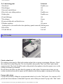
pg. 2 General Information
Before moving from one country to another it is recommended to check with the Department of Motor
Vehicles as emissions and other vehicle regulations may be different.
pg. 3 Keys
file:///K|/ownersdocs/1978/1978_264_265/78264265_00.htm (3 of 4)12/22/2006 10:12:06 PM
1978 Volvo 264 265
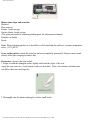
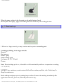
Write the key number codes on the inside of the front cover of this manual. (See tag attached to plastic
key ring).
In the event the original keys are lost, duplicates may be ordered from your Volvo dealer.
Top of Page
file:///K|/ownersdocs/1978/1978_264_265/78264265_00.htm (4 of 4)12/22/2006 10:12:06 PM
1978 Volvo 264 265
1978
VOLVO
264 265
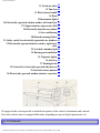
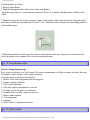
pg. 4 Instruments and controls
pg. 5 Instruments and controls
See page
1 Fresh air outlet 15
2 Turn signals 10
3 Headlights, parking lights 9
4 Instruments 6
5 Wiper/washer 11
6 Ignition switch/steering, wheel lock 8
7 Fresh air outlet 15
8 Clock 12
9 Fresh air outlet 15
10 Glove box -
file:///K|/ownersdocs/1978/1978_264_265/78264265_01a.htm (1 of 16)12/22/2006 10:12:07 PM
1978 Volvo 264 265
11 Fresh air outlet 15
12 Fuse box 64
13 Hood release handle 24
14 Horn 15 Instrument lights 9
16 Electrically operated window winder, left front door 12
17 Tailgate window wiper/wash (265) 13
18 Electrically heated rear window 13
19 Air conditioning 16
20 Hazard warning flasher 13
21 Safety switch for electrically operated rear windows 12
22 Electrically operated window winder, right front
12
door
23 Seat belt reminder light 20
24 Heating and ventilation 14
25 Cigarette lighter 12
26 Ash tray 12
27 Parking brake 8
28 Control for electrically operated side mirrors 25
29 Seat belt release buttons 20
30 Electrically operated window winders, rear door 12
The pages in this section provide a detailed description of the vehicle's instruments and controls.
Note that vehicles may be equipped differently, depending on special legal requirements, etc.
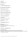
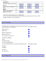
pg. 6 Instruments
file:///K|/ownersdocs/1978/1978_264_265/78264265_01a.htm (2 of 16)12/22/2006 10:12:07 PM
1978 Volvo 264 265
A Odometer
Total mileage reading.
B Speedometer
C Left turn signal indicator (green)
D Parking brake reminder light (red)
E High beam indicator (blue)
F Brake failure warning light (red)
G Right turn signal indicator (green)
H Oil pressure warning light (red)
I Alternator warning light (red)
J Trip odometer
(last figure represents 1/10 mile/km)
K Trip odometer reset knob
Push in to reset
L Reminder light, EGR Service
M Tachometer
Reads thousands of engine rpm.
Orange range for momentary use, during acceleration.
Red prohibited range.
N Bulb failure warning light (yellow)
O Temperature gauge
The gauge pointer should remain inside the black range during normal operation.
If the pointer enters the red range repeatedly, check coolant level and fan belt tension. (See section titled
"Cooling system and coolant".)
file:///K|/ownersdocs/1978/1978_264_265/78264265_01a.htm (3 of 16)12/22/2006 10:12:07 PM
1978 Volvo 264 265
P Overdrive indicator light (green)
Lights when overdrive is engaged.
R Fuel gauge
The fuel tank capacity is approx. 60 liters = 15.8 US gals/13.2 Imp. gals.
F Full
1/2
R Reserve
O Empty
The red range from R to O represents approx. 8 liters = 2.5 US gals. 1.2 Imp. gals.
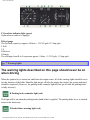
pg. 7 Warning lights
The warning lights described on this page should never be on
when driving
When the ignition key is turned on, and before the engine starts, all of the warning lights should be on to
test the function of the bulbs. Should a light not go off after the engine has started, the system indicated
should be inspected. (However, the parking brake reminder light will not go off until the parking brake
is fully released.)
D Parking brake reminder light (red)
This light will be on when the parking brake (hand brake) is applied. The parking brake lever is situated
between the front seats.
F Brake failure warning light (red)
file:///K|/ownersdocs/1978/1978_264_265/78264265_01a.htm (4 of 16)12/22/2006 10:12:07 PM
1978 Volvo 264 265
If the light comes on while driving and the brake pedal can be depressed further than normal, it is an
indication that one of the brake circuits is not functioning. Proceed cautiously to a Volvo dealer for an
inspection of the brake system.
H Oil pressure warning light (red)
If the light comes on during driving, the oil pressure is too low. Stop the engine immediately and check
the engine oil level. See section titled "Engine Oil".
After hard driving, the light will come on occasionally when the engine is idling. This is normal,
provided it goes off when the engine speed is increased.
I Alternator warning light (red)
If the light comes on while the engine is running, check the tension of the alternator drive belt as soon as
possible. (See section titled "Cooling system".)
NOTE:
This warning light is illuminated if the alternator is not charging. However, oil pressure, alternator,
parking brake, brake failure, EGR, and bulb failure will be illuminated at the same time due to the
design of the system.
L EGR service reminder light (red)
If the vehicle is equipped with exhaust gas recirculation, this light will come on at 15,000 mile intervals,
as required by U.S. Environmental Protection Agency. This is a reminder to have the EGR valve
serviced. The light will stay on until reset by servicing dealer.
N Bulb failure warning light (yellow)
The light will come on if any of the following bulbs are defective:
one of the lower beams
one of the tail lights
one of the license plate lights
one of the brake lights (when the brake pedal is depressed).
See section on "Replacing Bulbs".
pg. 8 Ignition switch, parking brake
file:///K|/ownersdocs/1978/1978_264_265/78264265_01a.htm (5 of 16)12/22/2006 10:12:07 PM
1978 Volvo 264 265
Ignition switch/steering wheel lock
The steering wheel lock might be under tension when the car is parked. Turn the steering wheel slightly
to free the ignition key.
A buzzer will sound if the ignition key is in the ignition lock and the front door on the driver's side is
open.
The buzzer goes off when the front door is closed.
Parking brake (hand brake)
The lever is situated between the front seats. The brake is applied to the rear wheels.
In order to obtain the best possible performance of the parking brake, the brake linings should be broken
in. (See section titled "Brake System".)
file:///K|/ownersdocs/1978/1978_264_265/78264265_01a.htm (6 of 16)12/22/2006 10:12:07 PM
1978 Volvo 264 265
Parking brake reminder light
The reminder light PARKING BRAKE on the instrument panel comes on whenever the parking brake
lever is not fully released and the ignition is on.
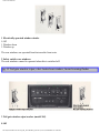
pg. 9 Lighting
Headlights and position lights
All lights off
Parking lights on
Headlights and parking lights on
file:///K|/ownersdocs/1978/1978_264_265/78264265_01a.htm (7 of 16)12/22/2006 10:12:07 PM
1978 Volvo 264 265
Switch from upper to lower beams, and vice versa, by moving the turn signal switch lever on the left
side of the steering column towards the steering wheel. The lights can be used without switching on the
ignition key.
Instrument panel lamps rheostat
Clockwise - brighter
Counterclockwise - dimmer.
pg. 10 Turn signals
file:///K|/ownersdocs/1978/1978_264_265/78264265_01a.htm (8 of 16)12/22/2006 10:12:07 PM
1978 Volvo 264 265
Turn signals
1 Signal lever engaged for normal turns.
2 Lane change position. In maneuvers such as lane changing, the driver can flash the turn signals by
moving the turn signal lever to the first stop and holding it there. The lever will return to the neutral
position when released.
3 High and low beam switching (headlights on).
Move the lever towards the steering wheel and release it.
3 Headlight flasher (headlights off).
Move the lever towards the steering wheel. The headlight high beam will be on until the lever is
released.
pg. 11 Windshield wipers
file:///K|/ownersdocs/1978/1978_264_265/78264265_01a.htm (9 of 16)12/22/2006 10:12:07 PM
1978 Volvo 264 265
Wiper/washer
1 Intermittent wiper.
With switch in this position, the wipers will make a stroke every seventh second.
2 "Single stroke" position.
Switch returns automatically when released.
3 Wipers, low speed.
4 Wipers, high speed.
5 Wiper and washer.
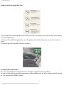
Adjusting washer nozzles
The nozzle may be adjusted by inserting a needle into the metal nozzle and rotating nozzle to desired
position.
file:///K|/ownersdocs/1978/1978_264_265/78264265_01a.htm (10 of 16)12/22/2006 10:12:07 PM
1978 Volvo 264 265
The washer fluid reservoir for the windshield is located in the engine compartment and holds approx. 6
liters = 1.6 US gals/1.3 Imp. gals.
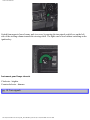
pg. 12 Clock, cigarette lighter, ash tray, electrically operated windows
Clock
To reset the hands, push in the reset knob and turn.
Cigarette lighter
To operate, depress the knob fully. When the knob automatically releases, the cigarette lighter is ready
for use.
Ash trays
To remove the ash trays depress the center spring and remove.
file:///K|/ownersdocs/1978/1978_264_265/78264265_01a.htm (11 of 16)12/22/2006 10:12:07 PM
1978 Volvo 264 265
1 Electrically operated window winder
0 Off
1 Window down
2 Window up
The rear windows are operated from between the front seats.
2 Safety switch, rear windows
The rear windows cannot be operated when this is switched off.
pg. 13 Tail gate window wiper, elect. heated rear window, hazard warning flasher
3 Tail gate window wiper/washer (model 265)
0 Off
file:///K|/ownersdocs/1978/1978_264_265/78264265_01a.htm (12 of 16)12/22/2006 10:12:07 PM
1978 Volvo 264 265
1 Wiper and washer combined operation.
Move the lever to the first stop and hold it there.
2 Tail gate wiper only.
The fluid reservoir is located in the concealed storage area under the floor on the right side of the rear
cargo area. Reservoir is approx. 1.5 qts.
4 Electrically heated rear window (demist)
0 Off
1 On
Switch off the rear window demister when the glass is clear of mist or frost. Otherwise the battery will
be unduly strained.
Do not place items against the inner surface of the rear window that may damage the printed circuit. Do
not scrape the inner surface of the rear window glass with a hard object, otherwise damage to the printed
circuit will occur.
5 Hazard warning flasher
0 Off
1 On
Four way flashing is used to indicate that the vehicle has become a traffic hazard (either during daylight
or at night).
Note: Regulations regarding the use of the hazard warning flasher may vary from state to state.
pg. 14 Heating and ventilation
file:///K|/ownersdocs/1978/1978_264_265/78264265_01a.htm (13 of 16)12/22/2006 10:12:07 PM
1978 Volvo 264 265
Heating system
1 TEMP
Left = cool
Right = warm
2 FLOOR
Out = no air to floor
In = full flow of air to front and rear floor
3 DEF (Defrost)
Out = low volume air flow to defroster
In = full flow
4 REC (recirculation)
To be used only for cars equipped with air conditioning.
Do not use for heating.
5 FAN (Blower motor)
0 = off
1 = low speed
2 = medium speed
3 = high speed
file:///K|/ownersdocs/1978/1978_264_265/78264265_01a.htm (14 of 16)12/22/2006 10:12:07 PM
1978 Volvo 264 265
6 Ventilation outlets
The air flow through the ventilation outlets is not influenced by the position of the FLOOR (2) and/or
DEF(3) controls.
pg. 15 Heating and ventilation
How to . . .
. . . obtain max. heat
1 TEMP >>> WARM
2 FLOOR depressed
5 FAN >>> 2(or 3)
6 All outlets halfway open
. . . remove condensation
1 TEMP >>>WARM
3 DEF depressed
5 FAN >>> 2 (or 3)
Always keep front external inlet grille (in front of the windshield) clear of obstructions (snow, ice, etc.).
Fresh air outlets
A Closed
file:///K|/ownersdocs/1978/1978_264_265/78264265_01a.htm (15 of 16)12/22/2006 10:12:07 PM
1978 Volvo 264 265
B Open
C Directing air flow horizontally
D Directing air flow vertically
Contents | Top of Page
file:///K|/ownersdocs/1978/1978_264_265/78264265_01a.htm (16 of 16)12/22/2006 10:12:07 PM
1978 Volvo 264 265
pg. 16 Air conditioning
Air conditioning
How to use the air conditioner:
1 FAN
Position 3 for rapid cooling.
2 AIR COND
Depress bottom end of switch to start the compressor.
The A/C does not operate unless FAN is on.
3 REC (Recirculation)
Push in for rapid cooling and during high humidity conditions.
4 TEMP
Position control to COOL for rapid cooling, then set to desired temperature.
To obtain rapid cooling, all windows must be closed and buttons FLOOR and DEF out.
Cool air will then be discharged through the four dash outlets which should be fully open.
Note: For rapid removal of condensation from inside glass surfaces, the air conditioner can be switched
on even when not required for interior cooling. The air conditioner will dehumidify the air inside the
vehicle.
Have your Volvo dealer check the system for correct operation yearly.
pg. 17 Radios, AM-FM-FM stereo-CB/Tape players
file:///K|/ownersdocs/1978/1978_264_265/78264265_01b.htm (1 of 15)12/22/2006 10:12:08 PM
1978 Volvo 264 265
Operating instructions
This equipment is optional and is available in various models, each providing slightly different
capabilities. Operating instructions are contained in the manuals associated with each model.
These manuals are placed in the cars when the equipment is installed by the Dealer.
Your Volvo Dealer will be able to assist you with any questions regarding the operation of this
equipment.
NOTE: Operation of Citizens Band (CB) radios is governed by Federal Regulations.
You must obtain a special license before operation this equipment.
pg. 18 Front seats
Horizontal seat adjustment
Pull control upward, then slide seat forward or rearward to desired position.
Seat back inclination adjustment
Rotate control clockwise to tilt seat back rearward.
Rotate counterclockwise to tilt seat back forward.
file:///K|/ownersdocs/1978/1978_264_265/78264265_01b.htm (2 of 15)12/22/2006 10:12:08 PM
1978 Volvo 264 265
Note that body weight must be shifted to allow seat back to move forward.
Lumbar support adjustment
Rotate clockwise for firm support or counterclockwise for soft support.
pg. 19 Front seats
Driver seat height
There are two levers, each with three positions, for adjusting the height of the seat (front and/or back of
cushion).
This allows adjustment of the seat cushion angle for added comfort.
After adjusting the seat, check that it is securely latched.
Note! Do not attempt to adjust seat height while seated.
file:///K|/ownersdocs/1978/1978_264_265/78264265_01b.htm (3 of 15)12/22/2006 10:12:08 PM
1978 Volvo 264 265
Passenger seat height
The front passenger seat is retained by four brackets, each with three positions. The positions are the
same as for the driver's seat.
However, this adjustment must be accomplished manually using appropriate hand tools.
pg. 20 Seat belts
Seat belts, retractable
Fasten the seat belts whenever you drive or ride.
Two lights will be illuminated for 4-8 seconds after the ignition key is turned to driving position. One
light is located in the instrument cluster and one in the console between the front seats.
A buzzer will sound at the same time if the driver has not fastened his seat belt.
The front and rear outboard seats are provided with self-retracting inertia belts.
file:///K|/ownersdocs/1978/1978_264_265/78264265_01b.htm (4 of 15)12/22/2006 10:12:08 PM
1978 Volvo 264 265
To buckle:
Pull the belt out from the retractor far enough to insert the latch plate into the receptacle (buckle for rear
seats), until a distinct snapping sound is heard. The belt should not be twisted or turned.
To unfasten, depress red pushbutton in receptacle (buckle) and let the belts rewind into their retractors.
The seat belt retractors are normally "unlocked'. The retractors will lock up as follows:
●
●
●
●
if belt is pulled out rapidly
during braking and acceleration
if the vehicle is leaning excessively
when driving in turns
Check seat belt mechanism function as follows:
1. Attach the seat belt. Pull rapidly on the strap.
2. CAUTION: Check other traffic before accomplishing this check.
Brake firmly from approximately 30 mph (50 km/h) or turn in a tight circle while pulling on the belt.
In all the above checks the belt should not be able to be pulled out.
file:///K|/ownersdocs/1978/1978_264_265/78264265_01b.htm (5 of 15)12/22/2006 10:12:08 PM
1978 Volvo 264 265
pg. 21 Seat belts
Seat belts, manually adjustable
The center rear seat belt is manually adjustable. It should always be adjusted to the correct length.
To lengthen, angle the buckle as shown in the illustration and pull the belt through.
To shorten, pull the upper part of the double webbing until snug.
Maintenance
Check periodically that the anchor bolts are secure and the belt in good condition.
Use water and a mild detergent for cleaning.
As the seat belts lose much of their strength when exposed to violent stretching, they should be
replaced after collision, even though they may appear to be undamaged.
Never modify or repair the belt on your own, but have this done by an authorized Volvo workshop.
pg. 22 Doors and locks
file:///K|/ownersdocs/1978/1978_264_265/78264265_01b.htm (6 of 15)12/22/2006 10:12:08 PM
1978 Volvo 264 265
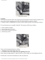
Unlocking front doors
Both front doors can be unlocked by using the key. Turning the key 1/4 turn counterclockwise lifts the
lock buttons on the window ledge and the door can be opened by pulling the handle.
Locking doors
All doors can be locked by depressing the lock buttons. To lock the front doors, press down the lock
button and keep the door handle pulled out while shutting the door.
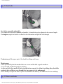
To lock the rear doors, press down the lock button and shut the door. It is not necessary to keep the door
handle pulled out.
To open a rear door from the inside, the lock button must first be pulled up.
The lock buttons should not be in the down position during driving. In case of an accident, this
may hinder rapid access to the occupants of the vehicle.
In wintertime the door locks should be "lubricated" with a suitable agent to prevent freezing. If the lock
is frozen, be careful not to break the key in the lock. Thaw the ice by heating the lock or the key.
file:///K|/ownersdocs/1978/1978_264_265/78264265_01b.htm (7 of 15)12/22/2006 10:12:08 PM
1978 Volvo 264 265
pg. 23 Rear doors, trunk lid
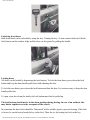
Child safety locks
The buttons are located on the rear door jambs.
A Normal lock function.
B The door cannot be opened from the inside.
Trunk lid , 264
To open th lid, turn the knob clockwise.
NOTE: The key must be removed from the lock in order to be able to open the lid.
The spare wheel, jack and tool kit are stowed in the left side of the trunk.
pg. 24 Hood
file:///K|/ownersdocs/1978/1978_264_265/78264265_01b.htm (8 of 15)12/22/2006 10:12:08 PM
1978 Volvo 264 265
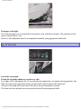
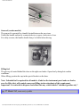
To open the hood
Pull the release handle (located under the left side of the dash).
Lift the hood slightly, insert a hand under the center line of the hood and depress the safety catch handle.
Open the hood.
Check that the hood locks properly when closing.
pg. 25 Rear/side view mirrors
Electrically operated side view mirrors
The control switches are located in front of the parking brake housing.
A Adjustment sideways
B Adjustment up/down
file:///K|/ownersdocs/1978/1978_264_265/78264265_01b.htm (9 of 15)12/22/2006 10:12:08 PM
1978 Volvo 264 265
Rear view mirror
D Normal position
N Night position, reduces glare from following headlights
The mirrors should always be adjusted before
driving.
pg. 26 Interior light, sun roof, fuel tank cap
Interior light
1 Light always on.
2 Light always off.
3 Light is on when either of the front or rear doors are opened.
Model 265 may be equipped with a light that differs from that in the 264.
file:///K|/ownersdocs/1978/1978_264_265/78264265_01b.htm (10 of 15)12/22/2006 10:12:08 PM
1978 Volvo 264 265
Sun roof (certain models)
The sun roof is operated by a handle located between the sun visors.
Unfold the handle and turn it counterclockwise to open, clockwise to close.
For safety reasons, the handle should always be folded when driving.
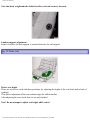
Filling fuel
The gas cap is located behind the door on the right rear fender. Open slowly during hot weather
conditions.
When filling, position the cap in the special bracket on the door.
Note: Unleaded fuel is required for all models. A label on the instrument panel and rear fender,
near the filler inlet, will remind owners and filling station attendants of this requirement.
Important! It is unlawful to dispense leaded fuel into any vehicle labeled "unleaded gasoline only".
pg. 27 Model 265, rear seat, eyelets
file:///K|/ownersdocs/1978/1978_264_265/78264265_01b.htm (11 of 15)12/22/2006 10:12:08 PM
1978 Volvo 264 265
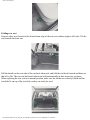
Folding rear seat
Depress either lever located at the front bottom edge of the rear seat cushion (right or left side). Tilt the
seat towards the front seat.
Pull the handle on the rear side of the seat back sidewards, and fold the seat back forward and down so
that it lies flat. The rear seat back and cushion are held automatically in their respective positions.
When replacing the rear seat to its normal position, make sure the latches are securely locked and the
seat belts lie on top of the seat back so they can easily be used.
file:///K|/ownersdocs/1978/1978_264_265/78264265_01b.htm (12 of 15)12/22/2006 10:12:08 PM
1978 Volvo 264 265
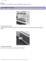
Eyelets
Six eyelets are provided in the cargo compartment for anchoring cargo.
pg. 28 Model 265, tailgate
To open from the outside
Unlock the lock using the trunk/glove box key. Depress the release button located under the tailgate
handle.
To open from the inside
Pull out the T-handle located at the bottom of the tailgate.
file:///K|/ownersdocs/1978/1978_264_265/78264265_01b.htm (13 of 15)12/22/2006 10:12:08 PM
1978 Volvo 264 265
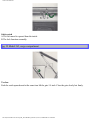
Safety catch
A The lid cannot be opened from the inside.
B The lock functions normally.
pg. 29 Model 265, cargo compartment
To close
Push the catch upwards and at the same time lift the gate 1/4 inch. Close the gate slowly but firmly.
file:///K|/ownersdocs/1978/1978_264_265/78264265_01b.htm (14 of 15)12/22/2006 10:12:08 PM
1978 Volvo 264 265
Spare wheel
Remove the two thumb screws and lift off the cover. The spare wheel is now accessible.
Concealed storage space
There are two concealed storage areas under the cargo compartment floor. The tailgate window washer
fluid reservoir is located in the right side area.
Contents | Top of Page
file:///K|/ownersdocs/1978/1978_264_265/78264265_01b.htm (15 of 15)12/22/2006 10:12:08 PM
1978 Volvo 264 265
1978
VOLVO
264 265
pg. 30 Service Inspection
STARTING AND DRIVING
Service Inspection
To ensure proper operation the car should be taken to a Volvo dealer between the first 600-1,200 miles
for a service inspection. The oil in the engine, transmission and rear axle will then be changed. This is
very important since the oil rapidly collects impurities during the break in period.
Every Volvo engine is test driven prior to delivery. Volvo is therefore assured that all clearances are
satisfactory. See also "Break in period" on next page.
pg. 31 Break in period
STARTING AND DRIVING
A new car should be broken in!
Manual transmission
During the break in period do not exceed the following speeds:
First 600 miles (1,000 km)
1st gear 20 mph (30 km/h)
2nd gear 30 mph (50 km/h)
3rd gear 50 mph (80 km/h)
4th gear 70 mph (110 km/h)1
1) 80 mph (130 km/h) with overdrive engaged. Do not use overdrive below 45 mph.
600-1,200 miles (1,000-2,000 km)
1st gear 25 mph(40 km/h)
2nd gear 45 mph (70 km/h)
3rd gear 60 mph (100 km/h)
file:///K|/ownersdocs/1978/1978_264_265/78264265_02.htm (1 of 11)12/22/2006 10:12:09 PM
1978 Volvo 264 265
4th gear 80 mph (130 km/h) 2
Avoid driving at low speed in high gear.
2) 90 mph (150 km/h) with overdrive engaged.
Automatic transmission
Refrain from using "kick-down" when driving a car equipped with an automatic transmission during the
first 1,200 miles.
pg. 32 Starting the engine
To start the engine:
WARNING!
Always open the garage doors fully before starting the engine inside the garage to ensure adequate
ventilation. The exhaust gases contain carbon monoxide, which is invisible and odorless but very
poisonous.
1 Enter the car and fasten the seat belt.
2 Apply the parking brake, if not already set.
3 Place the gear selector lever in neutral. (position N or P, automatic transmission).
4 Depress the clutch pedal (manual transmission).
5 Press down gas pedal about 1 inch (1/4 of total stroke).
6 Turn key to starting position. When engine has started, release the key and gas pedal.
If the engine does not start at once, depress the throttle pedal half way and keep it there until the
engine starts.
Avoid repeated short attempts to start (fuel is injected every time the starter is engaged when engine is
cold).
Allow the starter to operate for a longer time (but not more than 15-20 seconds).
Do not race a cold engine immediately after starting.
file:///K|/ownersdocs/1978/1978_264_265/78264265_02.htm (2 of 11)12/22/2006 10:12:09 PM
1978 Volvo 264 265
Engine warm-up - initial driving procedure
Experience shows that engines in vehicles driven short distances are subject to abnormally rapid wear
because the engine never reaches normal operating temperature.
It is therefore beneficial to reach normal operating temperature as soon as possible.
This is achieved by driving with a light load as soon as possible.
pg. 33 Gear shift positions
4-speed manual transmission
Depress the clutch fully when changing gears.
The following are recommended gear change speeds (level road).
Shift from first to second at 15 mph
Shift from second to third at 25 mph
Shift from third to fourth at 40 mph
No downshifts should be done when speed occasionally drops below the mentioned shift points.
file:///K|/ownersdocs/1978/1978_264_265/78264265_02.htm (3 of 11)12/22/2006 10:12:09 PM
1978 Volvo 264 265
Reversing inhibitor
Lift the ring to enter the reverse gear.
The ring locking mechanism prevents reverse gear from being engaged unintentionally.
Overdrive (some models only)
Shift to overdrive at 45 mph and disengage it when speed drops below 40 mph or encounters hilly
terrain. The overdrive can be engaged in 4th gear only.
No extra operation of clutch or throttle pedal is normally necessary. Engagement is facilitated if the
accelerator pedal position is maintained steady.
When disengaging, depressing the clutch pedal slightly makes a smooth transfer.
The overdrive should be used after the engine was reached normal operating temperature (minimum
time is five minutes) and the vehicle is being operated on relatively hard surfaces.
pg. 34 Automatic transmission
Shift positions
P park
file:///K|/ownersdocs/1978/1978_264_265/78264265_02.htm (4 of 11)12/22/2006 10:12:09 PM
1978 Volvo 264 265
R reverse
N neutral
D drive
2 intermediate
1 low
The gear selector can be moved freely between D and 2. The other positions are separated by a lockout
which is operated by depressing the selector knob.
Shift gate
Depressing the selector knob slightly allows selection of positions N and 1.
Depressing the selector knob fully allows selection of positions R and P. This is also necessary when
initially bringing the selector out of position P.
Depressing the selector knob fully thus permits shifting freely between all positions.
P Park
Use this position when parked with the engine running or stopped.
Never use P while car is in motion.
The transmission is mechanically locked in position P. Also use the parking brake when parking on
grades.
R Reverse
Never use R while car is moving forward.
N Neutral
Neutral position = no gear is engaged.
Driving gears
D Drive
D is the normal driving position. Upshift and downshift of the three forward gears occurs automatically
and is governed by throttle opening and vehicle speed.
pg. 35 Automatic transmission
2, Intermediate position
Upshift and downshift of first two gears (low and intermediate) occurs automatically.
No upshift to 3rd (top) gear occurs.
Position 2 may be used to obtain forced downshift to 2nd gear for increased engine braking effect.
Position 2 can also be used...
●
●
●
for relatively slow highway driving
for city driving
when driving on mountain roads where precise speed control is desirable
file:///K|/ownersdocs/1978/1978_264_265/78264265_02.htm (5 of 11)12/22/2006 10:12:09 PM
1978 Volvo 264 265
●
for passing
Top speed when selecting 2 is 75 mph (125 km/h).
1, Low position
If position 1 is selected when driving at high speeds, 2 is engaged first and 1 when the speed has
dropped to approx. 30 mph (50 km/h).
NOTE: No upshift once 1 is engaged.
Use position 1 to select low gear with no upshift. For instance, when entering and descending steep
grades.
Top speed when selecting 1 is 75 mph (125 km/h).
NOTE:
● Never select P or R while the car is in motion.
● When initially selecting D, 2 ,1 or R the car should be standing still with the engine idling.
● Never select positions 2 or 1 at speeds above 75 mph (125km/h).
Kick-down
Automatic shift to a lower gear is achieved by depressing the throttle pedal briskly(passing the normal
full throttle position).
An up-shift will be achieved when approaching the top speed for a particular gear or by releasing the
throttle pedal slightly.
Kick-down can be used for maximum acceleration or when passing at highway speeds.
Starting and stopping a car equipped with automatic transmission
1 Fasten the seat belts.
2 Apply the parking brake or the brake pedal to hold the car (to prevent the car from moving when the
gear selector is moved).
3 Select position P or N. (Engine cannot be started in any other position).
4 Start the engine by turning the ignition key.
5 Select desired gear.
6 Release the brake and accelerate.
To stop the car, release the throttle pedal and apply the brakes.
It is not necessary to move the gear selector as the transmission will downshift automatically.
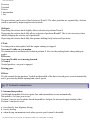
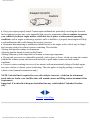
pg. 36 Emergency towing (pulling)
file:///K|/ownersdocs/1978/1978_264_265/78264265_02.htm (6 of 11)12/22/2006 10:12:09 PM
1978 Volvo 264 265
Precautionary steps to observe when towing
Steering must be unlocked.
● Observe legal speeds.
● Remember that power brake and power steering assists will not be available when engine is
inoperative. Pedal pressure required is 3 - 4 times above normal and greater steering effort must be
employed.
● Towing cars equipped with automatic transmission:
-Gear selector in position N. Check transmission oil level (see section titled "Transmission oil").
-Maximum speed: 20 mph (30 km/h).
-Maximum distance: 20 miles (30 km).
●
CARS EQUIPPED WITH AUTOMATIC TRANSMISSION CANNOT BE STARTED BY
PUSHING OR PULLING THE CAR.
When jump-starting, observe that the booster battery positive terminal (+) is connected to the car
battery positive terminal (+). The booster battery negative terminal (-) must be connected to the
car battery negative terminal (-). Any other connection will damage alternator and electronic
components.
pg. 37 Towing information
file:///K|/ownersdocs/1978/1978_264_265/78264265_02.htm (7 of 11)12/22/2006 10:12:09 PM
1978 Volvo 264 265
pg. 38 Trailer hauling
When preparing for trailer hauling, observe the following:
● Use a trailer hitch which meets Federal Safety Standards for rear end collisions (FMVSS 301-75)
such as those offered as Genuine Volvo Accessories.
● Maximum trailer weight recommended by Volvo is 2,000 lbs (908 kg).
Observe legal requirements of the state in which the vehicles are registered.
NOTE:
Additional lighting equipment must be connected to specific points in the electrical system. Otherwise
the bulb failure warning light will come on. (See your Volvo Dealer.)
Trailer hauling does not normally present any particular problems, but take into consideration:
● The hitch tongue load should not exceed 200 lbs (90 kgs).
● Engine and transmission are subject to increased loads.
● Avoid overload and other abusive operation.
● Hauling a trailer affects handling, durability and economy.
● It is necessary to balance trailer brakes with the towing vehicle brakes to provide a safe stop (check
and observe State regulations).
file:///K|/ownersdocs/1978/1978_264_265/78264265_02.htm (8 of 11)12/22/2006 10:12:09 PM
1978 Volvo 264 265
●
More frequent vehicle maintenance is required.
Roof rack
● Use a sturdy roof rack, intended for the vehicle and rigidly attached.
It is not advisable to let the roof rack remain in place during extended periods of time. Also, an empty
roof rack increases drag and fuel consumption.
● Avoid point loads. Distribute the load evenly.
● Place the heavy cargo at bottom of load.
● Observe that center of gravity and handling are influenced by the load weight.
● Increasing load size increases wind resistance.
● Anchor the cargo correctly with a cord.
● Drive carefully. Avoid rapid starts, heavy cornering and heavy braking.
● Max. roof load is 220 lbs (100 kg).
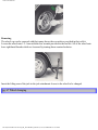
Handling, roadholding
Vehicle load, tire design and inflation pressure are important for proper handling. Therefore check that
the tires are inflated to the recommended pressure according to the vehicle load.
It is recommended to use tires of the same make and dimensions on all four wheels.
CAUTION!
Do not mix radial ply and bias ply tires as this will adversely alter the vehicle handling
characteristics.
Driving with trunk lid open
Normally this involves no hazard to the passengers. However, exhaust gases can be sucked into the car.
As this is especially true for the 265 model always heed the following safety precautions.
● Close the windows.
● Set the heating system FLOOR and DEF controls to max. and the blower to full speed (3). See section
titled "Heating and Ventilation".
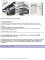
pg. 39 Brake system
Moisture on brake discs and brake pads affects braking.
Driving in rain and slush or passing through a normal car wash can cause water to collect on the brake
discs and pads. This will cause a delay in braking effect when the pedal is depressed. To avoid such a
delay, when the brakes are needed, depress the pedal occasionally when driving.
This will remove the water from the brakes.
This should also be done after washing or starting in very damp weather.
If the brake power assist does not functionfile:///K|/ownersdocs/1978/1978_264_265/78264265_02.htm (9 of 11)12/22/2006 10:12:09 PM
1978 Volvo 264 265
The power assist to the brakes functions only when the engine is running. When the car is moving
without the engine running the brake pedal pressure required to stop the car is increased 3 - 4 times.
The brake pedal feels stiff and hard.
If one of the brake circuits should malfunction the red warning light comes on (F page 6). The
pedal stroke increases slightly and the pedal feels softer but the pedal pressure required does not increase
noticeably.
Drive cautiously to a Volvo dealer or Service Station to have the brake system checked.
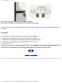
Breaking in parking brakes
To obtain best parking brake performance, the brake linings should be broken in.
Stop 5-7 times from 30 mph, transmission in neutral. Apply the parking brake lever, release button
pressed in during the stop.
The force must not lock the rear wheels. If this happens, release the brake enough to let the wheels
rotate. Drive a mile between each stop to cool the brakes. Check for proper parking brake operation.
NOTE:
The brake lights are not illuminated when applying the parking brake. To warn traffic from behind it is
therefore advisable to depress the brake pedal slightly to illuminate the stop lights.
Severe strain on the brake system.
The brakes will be subject to severe strain when driving in mountains or hilly areas.
The speed is usually low which means that the cooling of the brake is less efficient than when driving on
level roads.
To reduce the strain on the brakes it is advisable not to use the brakes excessively.
Instead, shift into a lower gear and let the engine help with the braking. A good rule is to use the same
gear downhill as would be used uphill. For vehicles with automatic transmission use position 2 or in
some cases 1.
pg. 40 Catalytic Converter
Catalytic Converter Cautions
file:///K|/ownersdocs/1978/1978_264_265/78264265_02.htm (10 of 11)12/22/2006 10:12:09 PM
1978 Volvo 264 265
Keep your engine properly tuned. Certain engine malfunctions, particularly involving the electrical,
fuel or ignition systems, may cause unusually high converter temperatures. Do not continue to operate
your vehicle if you detect engine misfire, noticeable loss of power or other unusual operating
conditions, such as engine overheating, repetitive stalls or backfires. A properly tuned engine will help
avoid malfunctions that could damage the catalytic converter.
● Remember that tampering or unauthorized modifications to the engine or the vehicle may be illegal
and can cause catalyst or exhaust system overheating. This includes:
Altering fuel injection settings or components.
Adjusting ignition timing beyond specified limits.
Altering emission system components or location or removing components.
● Do not park your car over combustible materials, such as grass or leaves, which can come into contact
with the hot exhaust system and cause such materials to ignite under certain wind and weather
conditions.
● Excessive starter cranking (in excess of one minute) with an intermittently firing or flooded engine,
can cause catalyst or exhaust system overheating. This also applies to lengthy pushing or towing of
vehicle to start (manual transmissions only).
●
NOTE: Unleaded fuel is required for cars with catalytic converter. A label on the instrument
panel and rear fender, near the filler inlet, will remind owners and filling station attendant of this
requirement.
Important! It is unlawful to dispense leaded fuel into any vehicle labeled "unleaded Gasoline
only".
Contents | Top of Page
file:///K|/ownersdocs/1978/1978_264_265/78264265_02.htm (11 of 11)12/22/2006 10:12:09 PM
1978 Volvo 264 265
1978
VOLVO
264 265
pg. 41 Maintenance service
MAINTENANCE
Maintenance services
Your Volvo has passed two major inspections before it was delivered to you. One was made at the
Volvo factory and one was performed by the dealer, according to Volvo specifications. When driven
600-1,200 miles, your car should be brought to the Volvo dealer for a service inspection. Engine,
transmission and rear axle oils, will be changed at this time.
Following this inspection, maintenance inspections as outlined in this book should be performed
every 7,500 miles.
The extended maintenance inspection intervals make it even more advisable to follow this program.
Inspection and service should also be performed any time a malfunction is observed or suspected.
Retain receipts for all vehicle emission services to protect your emission warranty.
See your "Warranties and Maintenance Records Manual".
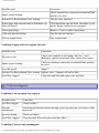
Maintenance inspection 7,500 mile intervals
Volvo advises you to follow the inspection program at 7,500 mile intervals which is outlined in the
"Warranties and Maintenance Records Manual". This maintenance program contains inspections and
services necessary for the proper functioning of your car over the next 7,500 miles.
The maintenance inspections contain several checks which require special instruments and tools and
therefore must be performed by a qualified technician.
To keep your Volvo in top condition, specify time tested and proven Genuine Volvo Parts and
Accessories.
THE FEDERAL CLEAN AIR ACT (USA)
The Clean Air Act requires vehicle manufacturers to furnish written instructions to the ultimate
purchaser to assure the proper functioning of those components that control emissions.
The maintenance instructions listed in the "Servicing" section of this Manual represent the minimum
maintenance required. These services are not covered by the warranty. You will be required to pay for
labor and material used. Refer to your "Warranties and Maintenance Records Manual" for further details.
file:///K|/ownersdocs/1978/1978_264_265/78264265_03a.htm (1 of 17)12/22/2006 10:12:10 PM
1978 Volvo 264 265
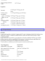
pg. 42 Gas station checks
Fuel RON 91
Octane rating 91
Unleaded fuel must be used as the vehicles are fitted with catalytic converters.
Engine oil
Maintain oil level between the dipstick marks. The distance between the marks represents 2 quarts (2
liters). Engine oil "For API service SE" SAE 10 W-40.
(See section titled "Engine oil".)
Coolant
Maintain fluid level between MAX and MIN marks on expansion tank.
Mixture of 50 percent anti-freeze and 50 percent water should be used.
Washer fluid
Washer fluid reservoir.
Water and solvent (wintertime use windshield washer anti-freeze).
Brake fluid
Hydraulic clutch
Clutch fluid (only cars with manual transmission).
Check that the level is above the MIN mark, without removing the cap.
Brake fluid DOT 3 or DOT 4(SAE J 1703).
Battery
Electrolyte level 1/4" - 3/8" above plates.
Use distilled water only. Never add acid.
WARNING!
battery gases are explosives if brought in contact with open flame or
sparks.
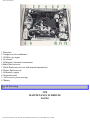
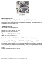
pg. 43 Engine B27F
file:///K|/ownersdocs/1978/1978_264_265/78264265_03a.htm (2 of 17)12/22/2006 10:12:10 PM
1978 Volvo 264 265
1 Data plate
2 Compressor (Air conditioner)
3 Oil filler cap, engine
4 Air cleaner
5 Oil dipstick, automatic transmission
6 Brake fluid reservoir
7 Clutch fluid reservoir (cars with manual transmission)
8 Washer fluid reservoir
9 Oil dipstick, engine
10 Expansion tank
11 Oil reservoir, power steering
12 Battery
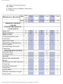
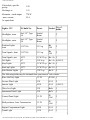
pg. 44 Servicing
1978
MAINTENANCE SCHEDULE
264 265
file:///K|/ownersdocs/1978/1978_264_265/78264265_03a.htm (3 of 17)12/22/2006 10:12:10 PM
1978 Volvo 264 265
A= Adjust (Correct if necessary)
R= Replace
I= Inspect (Correct or Replace if necessary)
L= Lubricate
600-
Maintenance Operation Miles 1,200
(Km)
EMISSION CONTROL
SYSTEM
I ENGINE MECHANICAL
COMPONENTS
Engine Oil *
Engine Oil Filter *
Engine Coolant
Cooling System Hoses and
Connections
Engine Drive Belts
Torque Exhaust Manifold Nuts
Valve Clearance
Vacuum Fittings, Hoses and
Connections
II ENGINE FUEL SYSTEM
Fuel (Line) Filter
Air Cleaner Filter
Idle RPM
Mixture Ratio and Manifold
Balance
Fuel System Cap, Tank, Lines and
Connections
Fuel Injection Electrical
Connections
Oxygen Sensor
Electrical connections in oxygen
sensor system
7,500
15,000 22,500 30,000 37,500 45,000
(1,000(12,500) (25,000) (37,500) (50,000) (62,500) (75,000)
2,000)
R
R
R
R
I
I
A
R
R
R
R
I
I
I
R
R
R
R
R
I
I
I
R
R
I
I
I
I
I
I
I
I
I
I
R
R
I
I
I
I
I
I
I
I
I
I
I
R
R
R
I
I
I
file:///K|/ownersdocs/1978/1978_264_265/78264265_03a.htm (4 of 17)12/22/2006 10:12:10 PM
1978 Volvo 264 265
* Oil and oil filter cartridge are first changed at the 600-1,200 mile inspection. Subsequent oil and
filter changes should be made at 7,500 mile intervals or at least every sixth month. However,
adverse conditions (like hot ambient temperatures, trailer hauling, hill climbing, driving long
distances at high speeds, extended periods of idling or low speed operation, short trip operation at
freezing temperatures) require oil changes more frequently (every third month).
pg. 45 Servicing
1978
MAINTENANCE SCHEDULE
264 265
A= Adjust (Correct if necessary)
R= Replace
I= Inspect (Correct or Replace if necessary)
L= Lubricate
600-
Maintenance Operation Miles 1,200
(Km)
EMISSION CONTROL
SYSTEM
III ENGINE IGNITION
COMPONENTS
Spark Plugs
Distributor Advance Mechanism
Ignition Timing
Distributor Cap and Rotor
Ignition Wiring
Timing Delay Valve
IV ENGINE CRANKCASE
VENTILATION SYSTEM
PCV Nipple (Orifice)
Ventilation Hoses
Oil Filter Breather Cap and Flame
Arrester
7,500
15,000 22,500 30,000 37,500 45,000
(1,000(12,500) (25,000) (37,500) (50,000) (62,500) (75,000)
2,000)
R
I
R
I
I
I
I
R
R
I
I
I
I
I
I
I
I
I
I
I
I
file:///K|/ownersdocs/1978/1978_264_265/78264265_03a.htm (5 of 17)12/22/2006 10:12:10 PM
I
I
I
1978 Volvo 264 265
V ENGINE EXTERNAL
EMISSIONS
Exhaust Gas Recirculation
Components
Throttle Valve Switch
Catalytic Converter Mounting Bolts
Reset Service Indication System
for oxygen sensor system
VI ENGINE EVAPORATIVE
EMISSIONS
Evaporative Control Canister
A
I **
I ***
I ***
I
A
I
A
I
A
A
A
A
R
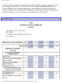
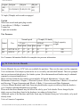
** Functional check
*** Clean EGR valve, Functional check
pg. 46 Servicing
1978
MAINTENANCE SCHEDULE
264 265
A= Adjust (Correct if necessary)
R= Replace
I= Inspect (Correct or Replace if necessary)
L= Lubricate
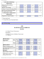
Maintenance
Operation
Miles
(Km)
DRIVE TRAIN
Manual Transmission Oil
Automatic Transmission Oil 1
Rear Axle Oil
BRAKES
Inspect Brakes. Replace
components as necessary.
Change Brake Fluid
6001,200
7,500
15,000 22,500 30,000 37,500 45,000
(1,000(12,500) (25,000) (37,500) (50,000) (62,500) (75,000)
2,000)
R
I
R
I
I
I
I
I
I
I
file:///K|/ownersdocs/1978/1978_264_265/78264265_03a.htm (6 of 17)12/22/2006 10:12:11 PM
I
I
I
R
I2
I
I
I
I
I
I
I
I
I
R
1978 Volvo 264 265
STEERING
Tire Wear (Align front end if
needed.)
Check power steering fluid
level.
BODY
Trunk, Door and Hood
Hinges and Latches.
I
I
I
I
I
I
I
I
I
I
I
I
I
I
L
L
L
L
L
L
L
1) Check the oil level (at least every sixth month).
2) For cars used for hard driving, or in hilly terrain etc, perform preventive service. This
includes oil changes every 30,000 miles.
pg. 47 Servicing
The following items should be checked weekly by the driver.
Description on page
(This only takes a few moments.)
48
Engine oil level
Brake fluid
57
Radiator coolant level
59
Battery fluid level
42
Tire pressures, all five tires
85
Operation of all lights
Horns
Windshield wipers
Level of windshield fluid
The following should also be carried out regular intervals.
Washing
Description on page
68
Polishing
68
Cleaning
69
Rust protection
69
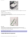
pg. 48 Engine oil
file:///K|/ownersdocs/1978/1978_264_265/78264265_03a.htm (7 of 17)12/22/2006 10:12:11 PM
1978 Volvo 264 265
A oil dipstick
B oil filler hole
Checking engine oil level
The oil level should be checked each time the fuel tank is refilled. Be sure the oil level is
maintained between the upper and lower marks on the dipstick. Low oil level can cause internal
damage to the engine and overfilling can result in high oil consumption. The distance between the
dipstick marks represents 2 quarts of oil.
To add oil or change oil
Add oil of the same kind as already used.
Capacity 6.8 US qts /5.7 Imp. qts. incl. filter
Oil type: API Service SE classification.
Viscosity:
All year round SAE 10W-40, SAE 10W-30
Above +14°F (-10°C) SAE 20W-50
Replace: Between the first 600-1,200 and every 7,500 miles (or at least twice a year).
At temperatures below 0°F, multigrade oil SAE 5W-20 or SAE 5W-30 is recommended. However,
this oil should not be used when the temperature is continuously above 32°F.
Driving under adverse conditions such as high ambient temperatures, trailer hauling, hill climbing,
driving long distances at high speeds, extended periods of idling, low speed operation or short trip
operation at freezing temperatures may require oil and filter changes more frequently (every third
month).
Drain the oil after driving while it is still hot.
file:///K|/ownersdocs/1978/1978_264_265/78264265_03a.htm (8 of 17)12/22/2006 10:12:11 PM
1978 Volvo 264 265
Changing oil filter
Replace the oil filter at every oil change. If the oil filter is changed separately, 1/2 qt. of oil should
be added.
pg. 49 Cooling system
Changing coolant
Every two years or 30,000 miles the cooling system should be drained, flushed and refilled.
Remove the expansion tank cap.
Open the drain cocks on both sides of the engine block and disconnect the lower radiator hose.
Fill coolant through the expansion tank.
The heater controls should be fully open when draining and filling.
Add coolant until the level is up to the MAX mark or slightly above.
file:///K|/ownersdocs/1978/1978_264_265/78264265_03a.htm (9 of 17)12/22/2006 10:12:11 PM
1978 Volvo 264 265
Start engine and run until hot. Check the cooling system connections for tightness. Also re-check
the coolant level.
Capacity: 11.5 US qts. /9.6 Imp. qts.
Cooling system, hoses and connections
Check all cooling system hoses and connections for defects or deterioration of hoses and loose
clamps or fittings.
Drive belts
The belt tension can be checked by depressing the fan belt at a point midway between the
alternator and fan. It should be possible to press down the belt about 1/4" - 3/8" (5-10 mm). This
also applies to other drive belts on the engine.
pg. 50 Emission control system
I Engine Mechanical Components
file:///K|/ownersdocs/1978/1978_264_265/78264265_03a.htm (10 of 17)12/22/2006 10:12:11 PM
1978 Volvo 264 265
Torque exhaust manifold nuts
The manifold nuts should be torqued at the 600-1,200 mile inspection. A loose manifold could alter
air/fuel ratio and cause an increase in emission and/or poor driveability.
Valves
The valve clearance should be checked every 30,000 miles.
Vacuum fittings, hoses and connections
Unstable idle, misfiring or poor emission control is often caused by leaking vacuum hoses or
connections. Check hoses and connections on distributor vacuum unit, EGR valve (when
applicable) and connections on heater control servo systems and hydraulic brake servo.
II Engine Fuel System
Fuel (91 octane)
Unleaded fuel is required for models with catalytic converter (all models).
A label on the instrument panel and on the rear fender, near the filler inlet, will remind of this
requirement.
It is unlawful to dispense leaded fuel into a vehicle labeled "unleaded gasoline only".
CI system
The B27F engine is provided with a fuel injection system called the CI system (Continuous
Injection). Fuel injectors are open and inject fuel as long as the engine is operating.
This system has few moving parts, is reliable and meets the exhaust emission standards at
maximum efficiency.
Air supplied to the engine is continuously measured and determines the amount of fuel injected.
The air flow is regulated by two throttle valves.
The air flow sensor and the fuel distributor are integrally built as a single unit. A lever is actuated
by the air flow to produce continuous fuel distribution.
Special instructions for work on the fuel injection system
Extreme cleanliness is essential when working on the injection system. Great care must be
observed.
Injection system service should be handled by qualified technicians, using equipment intended for
this service.
Fuel (line) filter
The fuel filter is located on the firewall. This filter is to be changed every 30,000 miles. The filter
is replaced as one complete unit.
Replace more frequently if contaminated fuel was introduced into the tank.
Air cleaner
file:///K|/ownersdocs/1978/1978_264_265/78264265_03a.htm (11 of 17)12/22/2006 10:12:11 PM
1978 Volvo 264 265
Replace the air cleaner cartridge with a new one every 30,000 miles. The cartridge should be
replaced more often when driving under dirty and dusty conditions. No cleaning of any kind is to
be accomplished.
pg. 51 Emission control system
Oxygen sensor system
This is a self-tuning engine control system designed to reduce emissions and improve fuel
economy.
An oxygen sensor monitors the composition of the exhaust gases leaving the engine. The exhaust
gas analysis is fed into an electronic unit which continuously influences a frequency valve. This
adjusts the air-fuel ratio to provide optimum conditions for combustion and efficient reduction of
the three major pollutants (hydrocarbons, carbon monoxide and nitrous gases) by a 3-way catalytic
converter.
Change oxygen sensor unit and inspect electrical connections of oxygen sensor system.
The oxygen sensor must be replaced every 15,000 miles.
At the same time the electrical wires and connections of the oxygen sensor system should be
inspected for chafing and corrosion.
Replace as necessary.
file:///K|/ownersdocs/1978/1978_264_265/78264265_03a.htm (12 of 17)12/22/2006 10:12:11 PM
1978 Volvo 264 265
pg. 52 Emission control system
Checking and adjusting idle speed and mixture ratio and manifold balance
This check should be made every 15,000 miles.
The idling speed should also be adjusted and the mixture ratio and manifold balance checked at the
600-1,200 mile inspection.
Fuel system cap, tank and lines and connections
The effectiveness of the fuel system to contain hydrocarbons is largely dependent on a leak-free
system. Check for proper sealing of gasoline filler cap which contains "O" ring type seals. Check
all evaporative hoses in vehicle for tightness. Check fuel lines under vehicle and repair if
necessary.
Inspection of fuel injection electrical connections
The electrical connections and fuel lines in the injection system should be checked for chafing and
corrosion every 15,000 miles.
III Engine Ignition Components
Change spark plugs
The spark plugs should be changed every 15,000 miles.
However, city driving or fast highway driving may require changing after 7,500 miles of driving.
When fitting new plugs, be sure to fit the right type (Volvo Part No. 273541-3 or equivalent). Use
molybdenum disulphide ("Molykote") to lubricate the threads and torque to 13-14.5 ft. lbs. (18-20
Nm).
When changing the plugs, check that the suppressor connectors are in good condition. Cracked or
damaged connectors should be replaced.
When changing spark plugs, clean the cables and cable terminals, also the rubber seals. If the car is
driven on roads where salt is used during the winter, coat the cables with silicone.
Ignition timing
Distributor advance mechanism
The ignition timing should be inspected at the 600-1,200 mile inspection and after that every
15,000 miles. All adjusting work should be done with the proper equipment. The distributor is one
of the most sensitive engine units. Careless handling can lead to decreased engine output and high
fuel consumption or even serious damage to the engine.
The distribute advance mechanism should be checked every 30,000 miles.
Ignition wiring
The ignition system consists of a primary and secondary system. The secondary system contains
the high tension leads connecting the distributor cap with the spark plugs and the coil.
file:///K|/ownersdocs/1978/1978_264_265/78264265_03a.htm (13 of 17)12/22/2006 10:12:11 PM
1978 Volvo 264 265
These wires should be inspected at each engine tune-up, and should be replaced if cracked, frayed
or damaged from abrasion. It is important to clean all parts of this secondary system thoroughly
because dirt greatly reduces the available voltage to the spark plugs.
Distributor cap and rotor
Check the distributor cap and rotor for wear, cracks, carbon formation, dirt and corrosion.
Timing delay valve
This valve should be replaced every 30,000 miles. A clogged valve will impair fuel economy. (Not
used on all models).
pg. 53 Emission control system
IV Engine Crankcase Ventilation System
1 Calibrated valve
2 Flame guard
Crankcase ventilation
The engine is provided with positive crankcase ventilation which prevents crankcase gases from
being released into the atmosphere.
Instead, the crankcase gases are admitted to the intake manifold and cylinders.
Cleaning PCV valve
The calibrated positive crankcase ventilation valve should be inspected every 15,000 miles and
cleaned if necessary. Rubber hoses should be checked for damage at the same time. Replace if
necessary.
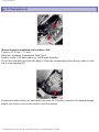
V Engine External Exhaust Emissions
file:///K|/ownersdocs/1978/1978_264_265/78264265_03a.htm (14 of 17)12/22/2006 10:12:11 PM
1978 Volvo 264 265
B Vacuum amplifier (some models)
C Thermostat
D Solenoid valve (some models)
E Micro switch (some models)
F EGR valve
G Exhaust manifold
H Intake manifold
Exhaust Gas Recirculation Components
Inspect and function check EGR valve and manifold nipple every 15,000 miles. Cleaned EGR
valve every 30,000 miles.
To remind the driver about the EGR service, there is a special EGR service reminder light which
comes on at 15,000 miles intervals.
(See section titled "Warning Lights".)
This is a reminder to have the EGR valve serviced. The light will stay on until reset.
pg. 54 Emission control system
Catalytic Converter
file:///K|/ownersdocs/1978/1978_264_265/78264265_03a.htm (15 of 17)12/22/2006 10:12:11 PM
1978 Volvo 264 265
This is a supplementary device in the exhaust system, designed to clean the remaining dirty exhaust
gases.
This device is mainly a container with a ceramic material insert, designed to let the exhaust gases
pass through channels in the insert. The channel walls are covered by a thin layer of platinapalladium. These metals act as catalysts, permitting a chemical action to occur without actually
taking part in it.
The CO content will increase if the Catalytic Converter is damaged.
Lambda-sond equipped vehicles use catalytic converters containing platinum and rhodium.
CAUTION:
Vehicles with Catalytic Converter must use unleaded fuel only. Otherwise the Catalytic
Converter will be destroyed.
Torque catalytic converter mounting bolts
The Catalytic Converter mounting bolts should be torqued every 15,000 miles.
pg. 55 Emission control system
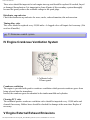
VI Engine Evaporative Emissions
Evaporative Control System
Vehicles intended for the North American market are equipped with a gas evaporative control
system, which prevents gas fumes from being released into the atmosphere.
The system consists of an expansion area in the fuel tank, a pressure relief valve and a charcoal
filter in the engine compartment.
The components are interconnected by hoses which channel fuel fumes from the gas tank to the
charcoal filter where they are stored until the engine is started and then drawn into the engine fuel
file:///K|/ownersdocs/1978/1978_264_265/78264265_03a.htm (16 of 17)12/22/2006 10:12:11 PM
1978 Volvo 264 265
induction system.
Evaporative Control Canister
Replace the canister every 45,000 miles.
Contents | Top of Page
file:///K|/ownersdocs/1978/1978_264_265/78264265_03a.htm (17 of 17)12/22/2006 10:12:11 PM
1978 Volvo 264 265
pg. 56 Transmission oil
Manual 4-speed transmission with overdrive, M46
Capacity: 2.4 US qts = 2.3 liters
Fluid type: Automatic Transmission Fluid Type F
Replace: at 600-1,200 miles and every 30,000 miles thereafter..
The oil level should be up to the filler plug(A). Drain the oil immediately after driving, while it is still
hot by removing plug (B).
Transmission and overdrive are lubricated by the same oil. Therefore, when the oil is drained through
plug B, also remove cover on the overdrive and clean strainer.
file:///K|/ownersdocs/1978/1978_264_265/78264265_03b.htm (1 of 14)12/22/2006 10:12:12 PM
1978 Volvo 264 265
Automatic transmission
Capacity: 7.0 US qts = 6.5 liters
Fluid
Automatic Transmission Fluid type F(FLM).
type:
Replace: no oil changes necessary under normal driving conditions.
When checking fluid level, the car should be on level ground, engine idling.
Move the gear selector slowly into all shift positions, then to position P. Wait two minutes before
checking. (Distance between Max and Min = 0.2 qts.)
NOTE: Dipstick graduations are for normal(range A) and cold (range B) transmission oil temperature.
When checking the fluid level, use a rag that will not leave lint.
pg. 57 Rear axle, power steering, brake fluid
Rear axle oil
Capacity: 1.7 US qts - 1.6 liters
Oil type: API GL-5 (MIL-L-2105 B or C)
file:///K|/ownersdocs/1978/1978_264_265/78264265_03b.htm (2 of 14)12/22/2006 10:12:12 PM
1978 Volvo 264 265
Viscosity: SAE 90
Replace: at 600-1,200 mile service only.
The oil level should be up to the filler plug (A).
Drain rear axle oil through drain plug (B).
When the temperature is steadily below 15° F = -10° C, use API GL-5 SAE 80 W oil.
Cars equipped with limited slip differentials should use oils with proper additives.
Power steering
Capacity: 1.25 US qts = 1.1 liters
Fluid type: ATF
Replace: no fluid change required.
The level should be between the MAX and MIN marks.
Check fluid level with engine idling and after driving while the fluid is still hot. Wipe the reservoir
clean.
Brake fluid
Clutch fluid (only on cars with manual transmission)
Fluid type: DOT 3 or DOT 4 (SAE J 1703)
file:///K|/ownersdocs/1978/1978_264_265/78264265_03b.htm (3 of 14)12/22/2006 10:12:12 PM
1978 Volvo 264 265
Replace: every third year or 45,000 miles . The clutch fluid does not need to be changed.
Check, without removing the cap, that the level is above the "MIN" mark of the fluid reservoirs.
Always entrust brake fluid changing to a Volvo dealer.
Change brake fluid every year when driving under extremely hard conditions (mountain driving etc).
pg. 58 Lubrication
Chassis maintenance
To simplify maintenance, your Volvo has been equipped with ball joints, steering rods and propeller
shafts that do not require regular lubrication.
Points that normally require lubricating have been packed with very durable grease at the factory and
then carefully sealed, eliminating the need for subsequent lubrication.
Lubricate body
To avoid rattles and unnecessary wear, the body should be lubricated once a year. Hinges on hood, doors
and trunk lid as well as door stops should be lubricated every 7,500 miles.
During winter, locks in the doors and trunk lid should be treated with special anti-freeze lubricant to
prevent freezing.
A. grease B. oil
file:///K|/ownersdocs/1978/1978_264_265/78264265_03b.htm (4 of 14)12/22/2006 10:12:12 PM
1978 Volvo 264 265
No. Lubricating point
Lubricant
1 Hood lock
Paraffin wax
2 Hood hinges
Oil
3 Sun-roof wind deflector
Oil
4 Door lock outer sliding surfaces
Paraffin wax
5 Striker plate
Paraffin wax
6 Trunk lid hinges
Oil
7 Door hinges
Grease
8 Front seat slide rails and latch devices
Oil
9 Window regulator
Oil, grease
Locking device (Accessible after door upholstery panels removed) Silicon grease
10 Key holes
Lock oil
11 Trunk lid lock
Lock oil
pg. 59 Coolant
Check coolant level
The cooling system must be filled with coolant and not leak to operate at maximum efficiency. Check
the coolant level when filling fuel. The level should be between the "Max" and "Min" marks on the
expansion tank. The check should be made with particular thoroughness when the engine is new or the
cooling system has been drained.
Do not remove the filler cap other than for topping-up with coolant. Frequent removal may prevent
coolant circulation between the engine and the expansion tank during engine warming up and cooling.
Top up with coolant
Top up with coolant by filling the expansion tank when level is at the "Min" mark. Use a mixture of 50
percent anti-freeze/summer coolant and 50 percent water all the year round. Top up to the "Max" mark.
file:///K|/ownersdocs/1978/1978_264_265/78264265_03b.htm (5 of 14)12/22/2006 10:12:12 PM
1978 Volvo 264 265
If the engine is warm, and you are going to top up coolant, unscrew the cap slowly in order to allow any
excess pressure to escape.
Note: Do not top up with water only. Water by itself reduces the rust-protective and anti-freeze qualities
of the coolant and has a lower boiling point. It can also cause damage to the cooling system if it should
freeze.
pg. 60 Replacing bulbs
Note: This car is equipped with an alternator.
When changing the battery or when carrying out work involving the electrical system, the following
should be observed:
1 A battery connection to the wrong terminal will damage the diodes. Before connections are made,
check the polarity of the battery with a voltmeter.
2 If booster batteries are used for starting, they must be properly connected to prevent the diodes from
being damaged.
The ground lead from the booster battery must be connected to the ground terminal of the car battery
and the positive lead from the booster battery to the positive terminal.
3 If a fast charger is used for charging the battery, the battery leads should be disconnected.
4 Never disconnect the battery circuit (for example, to change the battery) while the engine is running,
as this will immediately ruin the alternator.
Always make sure that all the battery connections are properly tightened.
5 If any electrical welding work is made on the vehicle, the ground lead and all the connecting cables of
the alternator must be disconnected and the welder wires placed as near the welding point as possible.
Replacing bulbs
The replacement of bulbs in the various lighting units is shown on the following pages. Make sure when
installing bulbs, that the guide pin on the socket fits into its corresponding recess.
When installing bulbs, do not touch the glass with your fingers. The reason for this is that grease, oil or
any other impurities can be carbonized onto the bulb and damage the reflector.
Replacing bulbs for instrument lighting and heater control lighting
Due to the location of the bulbs, their replacement should be carried out by a Volvo dealer.
Replacing bulbs for side marker lights
Remove the two Phillips screws which hold the lens. The bulb can now be removed by pressing it
inwards and turning it slightly counterclockwise.
pg. 61 Replacing bulbs
file:///K|/ownersdocs/1978/1978_264_265/78264265_03b.htm (6 of 14)12/22/2006 10:12:12 PM
1978 Volvo 264 265
Replacing sealed beam headlamp units
1. Press the two plastic screws down and turn them 1/4 turn and remove them.
2. Lift up the rim slightly and remove it forwards.
3. Remove the Phillips screws and rim. Lift out the headlamp unit.
4. Disconnect the socket contact.
Installation is done in the opposite way.
Check headlight alignment.
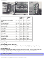
pg. 62 Replacing bulbs
file:///K|/ownersdocs/1978/1978_264_265/78264265_03b.htm (7 of 14)12/22/2006 10:12:12 PM
1978 Volvo 264 265
Power
US bulb
Socket
cp(w)
No
1 Front position, side marker
lights
264, 265 32(3)
Ba 15 d 1157 NA
2 Front turn signal
264, 265 32(3)
Ba 15 d 1157 NA
3 Rear turn signal
264
32(21) Ba 15 s 1073
4 Back-up light
264
32(21) Ba 15 s 1073
5 Stop light
264
32(21) Ba 15 s 1073
6 Tail light
264
4(5)
Ba 15 s 67
7 Reflector
264
-
-
8 Stop light
264
32(21) Ba 15 s 1073
9 Rear turn signal
265
32(21) Ba 15 s 1073
10 Back-up light
265
32(21) Ba 15 s 1073
11 Stop light
265
32(21) Ba 15 s 1073
12 Tail light
265
4(5)
-
Ba 15 s 67
Replacing bulbs
The front bulbs and rear bulbs (265)
Remove the Phillips screws retaining the lenses. Replace bulb by slightly depressing and turning
counterclockwise.
The rear bulbs on 264
Remove the board will lining on the inside of the rear wall of the trunk. Unscrew the two plastic nuts
securing the light glass. Replace bulb by slightly depressing and turning counterclockwise.
pg. 63 Replacing bulbs
file:///K|/ownersdocs/1978/1978_264_265/78264265_03b.htm (8 of 14)12/22/2006 10:12:12 PM
1978 Volvo 264 265
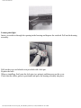
License plate light
Insert a screwdriver through the opening in the housing and depress the catch tab. Pull out the housing
assembly.
Pull out the cover end which is not provided with a lock pin.
Replace the bulb.
When re-installing, first locate the lock pins (see picture) and then press on the cover.
Check that the rubber gasket is positioned and press the housing assembly into place.
file:///K|/ownersdocs/1978/1978_264_265/78264265_03b.htm (9 of 14)12/22/2006 10:12:12 PM
1978 Volvo 264 265
Interior light
Insert a screwdriver through the opening in the right side of the housing and depress the catch tab. Pull
out the housing assembly and replace the bulb.
pg. 64 Fuses
Replacing fuses
The fuse box is positioned in front of the left front door pillar.
When replacing fuses, check that the right amperage is used.
The fuel feed pump fuse is located in the wire to the left under the mat in the trunk. Amperage: 5A.
The fuse holder is protected by two plastic tabs. Use a screwdriver to pry loose.
Never use fuses of higher amperage. If one fuse repeatedly fails, take the car to your Volvo dealer for
fault-tracing.
Reading downwards the fuses protect the following:
1 Lighter, Windshield wiper washer, Rear wiper washer (265)
2 Heater fan, Horn, Radio
file:///K|/ownersdocs/1978/1978_264_265/78264265_03b.htm (10 of 14)12/22/2006 10:12:12 PM
16A
16A
1978 Volvo 264 265
3 Rear demist, Overdrive
4 Back up lights, Air conditioning, Heated drivers seat, Relay window lift
5 Instrument, Turn signals, Control and warning lights, Relay, fuel injection system, Electrically
operated side mirrors
6 Stop lights, Rear interior light (265), Trunk light
7 Fuel pump
8 Clock, Glove compartment light, Interior light, Hazard
9 Seat belt warning
10 Window lifts
11 Left parking and side marker light, License plate light, left (265: left +right)
12 Right parking and side marker light, License plate light, right (not 265), Instrument and panel
lights, Seat belt light, Ash tray light, Shift positions light
16A
8A
8A
8A
16A
8A
8A
16A
8A
8A
pg. 65 Wheels and tires
General
Your Volvo is equipped with radial tires and pressed steel wheels as standard equipment. The wheel is
centered on the hub by means of a centering shoulder and (5) conical wheel nuts. If the wheel is
removed, care must be taken to properly center it on the hub before the nuts are tightened.
Snow tires
Studded snow tires require a running-in period of 300-600 miles. During this period avoid any hard
cornering, acceleration or braking.
Radial snow tires, with or without studs, are recommended for winter use.
Tire chains can be used on the rear wheels only providing that the chains do not project far enough from
the tire that they can chafe against the brake caliper or other components.
Strap-on emergency chains must not be used since the space between the brake calipers and the
wheel rims does not allow sufficient clearance.
Check tire wear pattern
Check the tires alr regular intervals for damage and abnormal wear. Also check for foreign particles in
the thread which may cause damage. Out of balance wheels increase tire wear and reduce riding comfort.
Always use a radial tire on the same side of the car throughout its lifetime.
To observe when replacing wheels
To avoid re-balancing, mark and re-install wheels in the same location as before removal.
Tire wear indicator
file:///K|/ownersdocs/1978/1978_264_265/78264265_03b.htm (11 of 14)12/22/2006 10:12:12 PM
1978 Volvo 264 265
The tires have a so-called "wear indicator" in the form of a number of narrow strips running across or
parallel to the tread. When approx. 1/16" = 1.5 mm is left on the tread, these strips show up and warn the
car owner that the tire should be replaced.
Check tire pressure
Check tire inflation pressure at regular intervals to avoid abnormal wear. The spare tire should also be
checked to ensure proper inflation when needed. Refer for "Specifications" section for correct tire
pressures.
Tire pressures should be checked when the tire is cool (before driving) as the pressure will increase after
driving due to heat build up in the tire. Air should be added to warm tires only when the pressure has
fallen below the recommended cold tire pressure level. Re-check pressure when tires are cold.
Too little pressure, is the most common reason for abnormal thread wear. Tires which are underinflated
will also cause high fuel consumption, heavy steering and poor road holding. Overinflated tires will
result in poor riding comfort.
pg. 66 Wheel changing
Changing a wheel
Spare wheel, jack and tool kit are stowed in the trunk compartment. Before raising the car with the jack
be sure it is on firm and level ground.
Note: Do not crawl or work under the car while it is raised by the jack.
Before the car is raised with the jack the parking brake should be applied and one of the gears engaged.
With automatic transmission, the selector should be in Park. Block one of the wheels on the opposite
side of the car from the jack.
file:///K|/ownersdocs/1978/1978_264_265/78264265_03b.htm (12 of 14)12/22/2006 10:12:12 PM
1978 Volvo 264 265
Removing
The wheel cap can be removed with the tommy bar or the screwdriver provided in the tool kit.
Loosen the wheel nuts 1/2-1 turn with the box wrench provided in the tool kit. All of the wheel nuts
have right-hand threads which are loosened by turning them counterclockwise.
Insert the lifting arm of the jack in the jack attachment closest to the wheel to be changed.
pg. 67 Wheel changing
file:///K|/ownersdocs/1978/1978_264_265/78264265_03b.htm (13 of 14)12/22/2006 10:12:12 PM
1978 Volvo 264 265
Be sure the arm goes all the way into the attachment.
Raise up the side of the car enough to lift the wheel off the ground.
Unscrew the wheel nuts completely and remove the wheel carefully so as not to damage the threads of
the studs.
Installation
Clean the nuts and the contact surface between wheel and hub.
● Lift on the wheel and fit the wheel center on the hub shoulder.
● Tighten the nuts until the wheel makes good contact with the flange.
● Lower the car and tighten the nuts alternately to 72-100 ft. lbs.
● Fit the wheel cap.
NOTE: Do not rotate a raised rear wheel if the car is equipped with a limited slip differential. This
will also move the opposite wheel on the ground and the car may slide off the jack.
●
Contents | Top of Page
file:///K|/ownersdocs/1978/1978_264_265/78264265_03b.htm (14 of 14)12/22/2006 10:12:12 PM
1978 Volvo 264 265
pg. 68 Washing, cleaning
Washing
The car should be washed at regular intervals since dirt, dust, insects and tar spots adhere to the paint
and may cause damage.
When washing the car, do not expose it to direct sunlight. Use lukewarm water to soften the dirt before
you wash with a sponge, and plenty of water, to avoid scratching.
A detergent can be used to facilitate the softening of dirt and oil.
Special car washing detergent or household detergent can be used. A suitable mixture is about 2.5 fl. oz.
(8.5 cl) of detergent to 2.6 US gal. (10 liters) of warm water. After washing with a detergent the car
should be well rinsed with clean water.
A water soluble grease solvent may be used in cases of sticky dirt. However, use a washplace equipped
with a drainage separator.
Dry the car with a clean chamois and remember to clean the drain holes in the doors and rocker panels.
Tar spots can be removed with kerosene or tar remover after the car has been washed.
Note: It is particularly important to wash the car frequently in the winter time, to prevent corrosion,
when salt has been used on the roads.
NOTE:
When the car is driven immediately after being washed, brake the car now and again in order to
remove any moisture from the brake linings.
Chromed parts
Chromium-plated and anodized parts should be washed with clean water as soon as they become dirty.
This is particularly important if you drive on gravel roads or on roads where salt is used during the
winter. After the car has been washed, apply wax or an anti-rust preparation.
Stains on chrome trim can be removed with commercially available chrome cleaner. Do not use abrasive
compounds or steel wool.
Polishing (waxing)
Polishing and waxing is not necessary unless a glossy surface can no longer be obtained by normal car
washing.
Normally, polishing is not required during the first year after delivery, however, waxing may be
beneficial.
Before applying polish or wax the car must be washed and dried. Tar spots can be removed with
kerosene or tar remover. Difficult spots may require a fine rubbing compound.
After polishing use liquid or paste wax.
Several commercially available products contain both polish and wax. Waxing alone does not substitute
for polishing of a dull surface.
file:///K|/ownersdocs/1978/1978_264_265/78264265_03c.htm (1 of 12)12/22/2006 10:12:13 PM
1978 Volvo 264 265
pg. 69 Cleaning
Cleaning the upholstery
Generally the fabric can be cleaned with soapy water or a detergent. For more difficult spots caused by
oil, ice cream, shoe polish, grease, etc., use a stain remover.
The Plastic in the upholstery can be washed.
Leather upholstery can be cleaned with a damp cloth or with saddle soap.
For more difficult spots, consult an expert for the choice of cleaning agent.
On no account must gasoline, naphtha or similar cleaning agents be used on the plastic or the leather
since these can cause damage.
Cleaning floor mats
The floor mats should be vacuumed or brushed clean regularly, especially during the winter when they
should be taken out for drying.
Spots on textile mats can be removed with a mild detergent.
Anti-rust treatment
Your Volvo has been rust protected at the factory. On external surfaces a heavy coat of wear resistant
material has been used, while on the internal surfaces a lighter rust protector is used.
The external rust protection should be inspected regularly or at least once per year.
If the rust protection has been penetrated a repair should be made as soon as possible to prevent moisture
from entering between the metal and coating. Carefully clean and remove any rust prior to repair of the
rust protective coating.
The internal rust protection should normally be renewed first time after 36 months and then at least
every 24th month.
pg. 70 Paint touch-up
Paint touch-up
Paint damage requires immediate attention to avoid rusting. Make it a habit to check the finish regularly,
for instance when washing the car. Touch-up if necessary.
Paint repairs require special equipment and skill. Contact your Volvo dealer for any extensive damages.
Minor scratches can be repaired by using Volvo touch-up paint.
Note: When ordering touch-up paint from your Volvo dealer, use the paint code indicated on the
Vehicle Designation plate. This plate is located at the right wheel well housing.
file:///K|/ownersdocs/1978/1978_264_265/78264265_03c.htm (2 of 12)12/22/2006 10:12:13 PM
1978 Volvo 264 265
Minor stone chips and scratches
Material:
Rust remover
Primer - brush on type
Surface finish - brush on type
(The paint pen head also contains grinding paste for subsequent treatment.)
Penknife or similar
Brush
Note: When touching-up the car, it should be well cleaned and dry and have a surface temperature
above +15°C(60°F).
Scars on the surface (where the paint has not been completely penetrated). Repairs can be made
directly after light scraping to remove dirt.
Deep scars, (down to the bare metal):
1 Scrape or sand the damaged surface lightly and break the edges of the scar.
Apply the rust remover. (Avoid contact with eyes and skin!). Wait a few minutes and then rinse
carefully with water and wipe dry.
2 Thoroughly mix the primer and apply it with a small brush.
file:///K|/ownersdocs/1978/1978_264_265/78264265_03c.htm (3 of 12)12/22/2006 10:12:13 PM
1978 Volvo 264 265
When the primer surface is dry, the paint can be applied using a brush.
Mix the paint thoroughly, apply several thin paint coats and let dry after each application.
pg. 71 Paint touch-up
3 If there is a longer scratch, you may want to mask to protect surrounding paint.
Touching-up flaking fender edges and sills
Material:
Rust remover
Primer - spray
Surface finish - spray
Sand paper (H 150 - 300 grit)
Thinner
Note: When touching-up the car, it should be well cleaned and dry and have a temperature exceeding
+15° C (60° F).
NOTICE! Spray paint may contain saturated chlorofluorocarbon propellant, sale of which may be
illegal in certain areas.
Mask with tape and paper prior to painting larger surfaces. Remove the masking immediately after
application of the last paint coat, before the paint starts to dry.
file:///K|/ownersdocs/1978/1978_264_265/78264265_03c.htm (4 of 12)12/22/2006 10:12:13 PM
1978 Volvo 264 265
Touching-up is as follows:
1 Remove paint flakes.
2 Sand the damaged surface and wash it clean with thinner.
Apply the rust remover. (Avoid contact with skin!) Wait a few minutes and then rinse carefully with
water.
3 Shake the spray can for at least 1 minute. Spray on the primer. Move the can slowly and evenly back
and forth over the spot and about 20-30 cm(8-12 in. ) from the surface. Protect the surrounding surfaces
with suitable paper.
4 When the primer has dried, apply the surface enamel in the same way. Spray on several times and
allow the paint to dry a minute or so between each application.
pg. 72 Long distance trips
Prior to a long distance trip
Have your car checked at a Volvo dealer. Preventive maintenance will help to ensure a trouble free trip.
Remember to take along a Volvo dealer directory.
The main items to check are listed below:
1. Brakes, front wheel alignment and steering gear.
2. Engine running condition.
3. Fuel system operation.
4. Oil leaks: engine, transmission, rear axle.
5. Cooling system for leaks or worn hoses.
6. Examine tires carefully, replace worn tires.
7. Battery and terminals.
8. Tool equipment.
9. Lighting.
10. Drive belts, for tightness and wear.
pg. 73 Cold weather
file:///K|/ownersdocs/1978/1978_264_265/78264265_03c.htm (5 of 12)12/22/2006 10:12:13 PM
1978 Volvo 264 265
Engine cooling system
A good quality anti-freeze/summer coolant should be used all year round. The cooling system should
always contain water plus anti-freeze and rust inhibitor, even during the summer. Experience has also
shown that extremely weak anti-freeze solutions (10-25 percent) are ineffective for rust protection. For
this reason, the quantity of anti-freeze/summer coolant should amount to about 50 percent of the
solution, that is 5.0 US qts. = 4.3 Imp. qts. = 4.8 liters This lowers the freezing point to -31° F (-35° C).
Alcohol must not be used as an anti-freeze agent since it evaporates at normal engine temperature.
Engine fuel system
During the winter, large variations in temperature cause condensation to form in the fuel tank and can
impair the running of the engine.
This can be eliminated by adding special additives to the fuel. There is less risk of condensation forming
in the fuel tank if it is kept full.
Engine lubricating system
During the winter, multigrade oil 10W-40 should be used in the engine. At very low temperatures below
(below 0° F), multigrade oil SAE 5W-20 or SAE 5W-30 is recommended. These oils reach the
lubricating points in the engine more easily at low temperature and also facilitate cold starting. See
section titled "Engine oil".
Electrical system
The electrical system is subject to great stresses during the winter. Lighting and starter motor are used
more often. The battery capacity is impaired at low air temperature. The state of charge must be checked
more frequently, and if necessary the battery should be charged. The battery may freeze if the state of
charge is low.
Brake system
During cold weather the brakes are subject to splash and condensation which can result in the parking
brake freezing up, especially if applied for long periods of time. Use of first or reverse gear on a manual
transmission or position "P" on an automatic transmission is preferable during these conditions. See
section titled "Brake System".
Windshield washers
Anti-freeze should also be added to the water container for the windshield (rear window) washer.
This is particularly important during the winter because the windshield frequently becomes dirty and is
often splashed with water which rapidly freezes. This may necessitate the frequent use of the windshield
washer and wipers. Your Volvo dealer can supply you with suitable anti-freeze for this purpose.
Anti-freeze for door locks
Lubricate the outside locks with a suitable anti-freeze. Such agents are commercially available and
should be used before the first frost.
file:///K|/ownersdocs/1978/1978_264_265/78264265_03c.htm (6 of 12)12/22/2006 10:12:13 PM
1978 Volvo 264 265
pg. 74
Volvo supports Voluntary Mechanic Certification by the N.I.A.S.E.
pg. 75 Service diagnosis
The diagnoses outlined below are intended to serve as a guide to locate and temporarily correct minor
faults. Causes of unsatisfactory performance should be investigated and corrected by your Volvo dealer.
NOTE: The points indicated by an asterisk (*) should be checked by your Volvo dealer.
Condition: Starter fails to operate (or operates very slowly)
Possible cause
Correction
Weak battery or dead cell.
With the ignition switch in the "Driving" or "On"
position, check to see if the warning lights on the
dashboard come on and if they stay on when the
starter is engaged.
If the lights do not come on or if they go off when
the starter is engaged, the battery is discharged or
see below.
Loose or corroded battery cable terminals.
Check battery terminals and clamps. Clean or
replace if necessary. Check that the starter cable is
secure at its terminals.
The ground strap, which connects the body to the
rear of the engine, should also be checked for
corrosion or looseness.
file:///K|/ownersdocs/1978/1978_264_265/78264265_03c.htm (7 of 12)12/22/2006 10:12:13 PM
1978 Volvo 264 265
The circuit is closed if a clicking sound is heard
from the starter when it is engaged. If no clicking
Open circuit between ignition/starter switch and
sound is heard, check that the blue wire at the starter
ignition switch terminal on starter.
is secure. If still no clicking sound is heard, the
ignition switch or the wire is defective.
Starter motor defective.
If the above checks have been performed, and no
fault is evident, the starter may be defective.
NOTE: In this case the headlight intensity will not
dim when the starter is engaged.
pg. 76 Service diagnosis
Condition: Starter motor operates but engine does not start
Possible cause
Correction
Intake system leaking.
Check vacuum hose connections at manifold and
auxiliary air valve.
No fuel reaching engine.
Check for fuel in the tank.
Check fuses No 7.
No spark
Remove one spark plug wire and unscrew the radio
interference suppressor. Hold the wire approx. 3/8"
from the valve cover and run the starter.
If there is no spark, check that the high tension lead
from the coil to the distributor cap is connected and
that the wires to the distributor and coil are connected.
Spark plugs, high tension leads or distributor
cap wet or defective.
Clean the parts with a dry cloth or spray with a
moisture remover. Replace defective or worn parts.
Cold start injector defective.
Test the cold start injector function with cold and hot
engine.*
Rest pressure incorrect.
Test rest pressure and the fuel system for leaks.*
If no fault is found following the above steps, contact
your Volvo dealer.
pg. 77 Service diagnosis
Condition: Erratic idle (misfiring)
file:///K|/ownersdocs/1978/1978_264_265/78264265_03c.htm (8 of 12)12/22/2006 10:12:13 PM
1978 Volvo 264 265
Possible cause
Correction
Intake system leaking.
Check vacuum hose connections at manifold and
auxiliary air valve.
Exhaust Gas Recirculation Valve leaking.
Test the valve function.*
Spark plugs, high tension leads or distributor cap
worn (defective).
Clean distributor cap and leads, check the cap for
cracks. Replace defective or worn parts.
Worn spark plugs.
Remove. Clean or replace spark plugs.
Cold start injector leaking.
Test the injector function.*
Uneven compression.
Test compression.*
Condition: Engine stalls at irregular intervals
Possible cause
Correction
Defective wires.
Check wire terminals at: fuel pump, fuse No. 7, coil,
distributor, ignition switch and relays and air flow sensor.
Intake system leaking.
Check vacuum hose connections at manifold and auxiliary
air valve.
Low idle speed.
Adjust.*
Exhaust Gas Recirculation Valve seizing. Replace valve.* (Engine will stall at idle.)
Fuel filter clogged.
Clean fuel tank filter and replace line fuel filter.
pg. 78 Service diagnosis
Condition: Low top speed, loss of power
Possible cause
Correction
Air filter clogged.
Check air filter.*
Throttle
misadjusted.
Check that the throttle touches the high speed stop when the accelerator is fully
depressed.*
Incorrect timing.
Check and adjust.*
Fuel filter clogged.
Clean fuel tank filter and replace fuel line filter.*
Condition: Excessive fuel consumption
file:///K|/ownersdocs/1978/1978_264_265/78264265_03c.htm (9 of 12)12/22/2006 10:12:13 PM
1978 Volvo 264 265
Possible cause
Correction
Fuel lines leaking.
Check tightness.
Spark plugs worn
Replace plugs.
Incorrect timing.
Check/adjust.*
Air filter clogged.
Check/replace.*
Control pressure
incorrect.
Check/replace control pressure regulator.*
Cold start injector
leaking.
Replace injector.*
(A leaking cold start injector also causes uneven idle and hard
starting.)
pg. 79 Service diagnosis
Condition: Dieseling
Possible cause
Correction
Injector
leaking.
Check air flow sensor plate and rest pressure.*
Condition: Misfiring at highway driving speed
Possible cause
Correction
Spark plugs
fouled.
Drive the vehicle in a lower gear and keep the engine rpm higher for a few miles
in order to remove carbon deposit on the spark plugs. If this procedure is not
effective, clean or replace the spark plugs.
Condition: Deceleration backfiring
Possible cause
Correction
Diverter valve
faulty.
Check diverter valve operation.*
pg. 80 Specifications
file:///K|/ownersdocs/1978/1978_264_265/78264265_03c.htm (10 of 12)12/22/2006 10:12:13 PM
1978 Volvo 264 265
Type designations
The VIN number should always be quoted in all correspondence concerning your vehicle with the dealer
and when ordering parts.
1 Vehicle Identification Number (VIN)
VIN plate is located on the body on the left windshield pillar. The VIN is also stamped on the right hand
door pillar.
2 Vehicle Emission Control Information
Your Volvo has been built to comply with all U.S.A. and Canada anti-pollution regulations and evidence
of this can be verified from the certification label on the left wheel valance. For further information
regarding these regulations, please consult your Volvo dealer.
3 Model Plate
Vehicle Identification Number (VIN), Version Identification Code (VIC) with information on engine
type, emission equipment etc, codes for color and upholstery, Gross Vehicle Weight (GVW). This plate
is located on right wheel valance.
4 Loads and Tire Pressures
5 Federal Motor Vehicle Safety Standards (FMVSS) specifications
These two labels are located on the left front door opening.
file:///K|/ownersdocs/1978/1978_264_265/78264265_03c.htm (11 of 12)12/22/2006 10:12:13 PM
1978 Volvo 264 265
Contents | Top of Page
file:///K|/ownersdocs/1978/1978_264_265/78264265_03c.htm (12 of 12)12/22/2006 10:12:13 PM
1978 Volvo 264 265
1978
VOLVO
264 265
pg. 81 Specifications
Dimensions and weights
Length
Width
Height, curb weight
Wheelbase
Ground clearance (full load)
Track, front
Track, rear
Turning circle (between curbs)
Curb weight (depending on
type)
Gross vehicle weight (GVW)
Capacity weight
Permissible axle weight, front
Permissible axle weight, rear
Max. trailer weight
Max. hitch load
264
191.7" (487 cm)
67.3" (171 cm)
56.5" (144 cm)
104.0" (264 cm)
4.9" (12.5 cm)
56.3" (143 cm)
53.5" (136 cm)
32.5' (9.8 cm)
3160-3225 lbs (1435-1465
kg)
4190 lbs (1900 kg)
920 lbs
2050 lbs (930 kg)
2180 lbs (990 kg)
2000 lbs (908 kg)
200 lbs. (90 kg)
Cargo Space
Length with rear seat up
Length with rear seat down
Maximum width
Height
Volume with rear seat up
Volume with rear seat down
Cargo opening, maximum width
265
44.5" (113 cm)
74.0" (188 cm)
53.1" (135 cm)
32.7" (83 cm)
42 cu. ft.(1.2 m3)
71 cu. ft.(2.0 m3)
45.7" (116 cm)
file:///K|/ownersdocs/1978/1978_264_265/78264265_04.htm (1 of 8)12/22/2006 10:12:13 PM
265
191.7" (487 cm)
67.3" (171 cm)
57.5" (146 cm)
104.0" (264 cm)
4.9" (12.5 cm)
56.3" (143 cm)
53.5" (136 cm)
32.5' (9.8 cm)
3260-3305 lbs (1480-1500
kg)
4300 lbs (1950 kg)
990 lbs
2050 lbs (930 kg)
2600 lbs (1180 kg)
2000 lbs (908 kg)
200 lbs. (90 kg)
1978 Volvo 264 265
Cargo opening, maximum
height
30.7" (78 cm)
Capacities
Fuel tank
Cooling system
Oil capacity:
- engine, at oil change
- engine, excl. oil
filter
transmission(M46)
(BW55)
rear axle
steering gear, power
15.8 US gals/13.2 Imp. gals. (60
liters)
11.5 US qts/9.6 Imp. qts. (10.9 liters)
6.8 US qts/5.7 Imp. qts. (6.5 liters)
6.3 US qts/5.3 Imp. qts. (6.0 liters)
2.4 US qts/2.2 Imp. qts. (2.3 liters)
7.0 US qts/5.7 Imp. qts. (6.5 liters)
1.7 US qts /1.4 Imp. qts(1.6 liters )
1.25 US qts/1.1 Imp. qts. (1.2 liters)
pg. 82 Specifications
ENGINE
Liquid-cooled, gasoline, 6-cylinder V-engine with 90° angle. Aluminum cylinder block with cast iron,
replaceable wet liners. Aluminum cylinder head has separate inlet and exhaust passages. Single,
overhead camshafts.
Engine lubrication is provided by a gear pump driven from the crankshaft. Full-flow type oil filter.
Exhaust emission control accomplished by fuel injection. Air Injection Reactor and Exhaust Gas
Recirculation (some models also equipped with catalytic converter).
Closed crankcase ventilation system and evaporative emission control system.
Type designation
Volvo B 27 F
Output (SAE J 245) at rpm
125hp1)/5750
Max. torque (SAE J 245) at rpm
150 ft. lbs.2)(198 Nm) /2750
6
3.46" (88 mm)
2.87" (73 mm)
2.66 liters
8.2:1
Number of cylinders
Bore
Stroke
Displacement
Compression ratio
file:///K|/ownersdocs/1978/1978_264_265/78264265_04.htm (2 of 8)12/22/2006 10:12:13 PM
1978 Volvo 264 265
Valve clearance cold engine
inlet
exhaust
0.004-0.006" (0.10-0.15 mm)
0.010-0.012" (0.25-0.30 mm)
1) With
air pump: 121 hp
catalytic converter: 148 ft. lbs.
Cooling system
2) With
Positive pressure, closed
system
188°F (82°C)
199°F (92°C)
HC-38 X 1125
Type:
Thermostat begins to open at
- fully open at
Fan belts, designation
Fuel System
The engine is equipped with fuel injection system.
pg. 83 Specifications
Ignition System
Firing order
Ignition setting
stroboscope setting with vacuum regulator disconnected, AC
off
Spark plugs
1-6-3-5-2-4
Spark plug gap
Tightening torque
Distributor, direction of rotation
0.028-0.032" (0.7-0.8 mm)
10-°+/-2° BTDC (at 700 - 800 rpm)
Volvo Part No. 273541-3 (or equivalent)
13-14.5 ft. lbs. (10-14 Nm)
Clockwise
ELECTRICAL SYSTEM
12 V, negative ground.
Voltage-controlled alternator. Single-wire system with chassis and engine used as conductors.
Voltage
Battery, type
-Capacity
12 V
Noack 12 H 70 B op*
70 Ah
file:///K|/ownersdocs/1978/1978_264_265/78264265_04.htm (3 of 8)12/22/2006 10:12:13 PM
1978 Volvo 264 265
-Electrolyte, specific
gravity
-Recharge at
Alternator , rated output
- max. current
*or equivalent
1.28
1.21
770 W
55 A
Socket
No. of
bulbs
Lights, 12 V
US bulb No.
Power
Headlights, inner
4x6 1/2" Type
1A
Sealed
Beam
2
Headlights, outer
4x6 1/2" Type
2A
Sealed
Beam
2
Position Lights,
front
1157 NA
32/3 cp
Ba
15d
2
Turn Signals, front
1157 NA
32/3 cp
Ba
15d
2
Turn Signals, rear
1073
21 W/32 cp
Ba 15s 2
Tail lights
67
5 W/4 cp
Ba 15s 4(265:2)
Stop Lights
1073
21 W/32 cp
Ba 15s 2
Back-up Lights
1073
21 W/32 cp
Ba 15s 2
Side Marker Lights
57
3 W/2 cp
Ba 9s
2
The following bulbs may be obtained from your nearest Volvo dealer.
Rear Ash Tray Light
1.2 W
W1.8d 1
License Plate Light
5W
S 8.5
2
Interior Light
10 W
S 8.5
1(265:2)
Glove box Light
2W
Ba9s
1
Instrument Panel Light
2W
Ba7s
3
Control Panel Light
1.2 W
W
1.8d
3
Shift positions, Auto Transmission
1.2 W
W
1.8d
1
Engine Compartment Light
15 W
S 8.5
1
Trunk Light
15 W
S 8.5
1
file:///K|/ownersdocs/1978/1978_264_265/78264265_04.htm (4 of 8)12/22/2006 10:12:13 PM
1978 Volvo 264 265
Warning Lamps
Charging
1.2 W
W
1.8d
1
Turn Signals
1.2 W
W
1.8d
2
Brake Failure
1.2 W
W
1.8d
1
Parking Brake
1.2 W
W
1.8d
1
Headlights
1.2 W
W
1.8d
1
Oil Pressure
1.2 W
W
1.8d
1
Overdrive
1.2 W
W
1.8d
1
Warning Flashers
1.2 W
W
1.8d
1
El. Heated Window
1.2 W
W
1.8d
1
EGR Reminder
1.2 W
W
1.8d
1
Seat Belts
2W
Ba9s
2
Bulb Failure
1.2 W
W
1.8d
1
pg. 84 Specifications
Front End
Suspension is of the McPherson type with the shock absorber mounted in a strut in the coil spring.
Rack and pinion steering gear.
Safety steering column.
Front wheel alignment
The alignment specifications apply to an unloaded car but include fuel, coolant and spare wheel.
Toe-in, : 1/8"= 0.12+/- 0.06" (3.0 +/- 1.5 mm), power steering
Camber : +1° to + 1 1/2 ° difference not to exceed 1/2° between left and right side.
Caster : not adjustable
file:///K|/ownersdocs/1978/1978_264_265/78264265_04.htm (5 of 8)12/22/2006 10:12:13 PM
1978 Volvo 264 265
POWER TRANSMISSION
Cable-operated clutch on the single, dry-plate type.
Floor-shift operated manual transmission has four synchromesh forward gears, one reverse and
electrically operated overdrive.
Optional automatic transmission.
Hypoid type final drive. Limited slip differential is optional.
Transmission
Type
designation:
Reduction ratios:
1st gear
2nd gear
3rd gear
4th gear
Overdrive
Reverse
Rear axle
M46 BW55
3.71:1 2.45:1
2.16:1 1.45:1
1.37:1 1.00:1
1.00:1 --0.80:1 --3.68:1 2.21:1
3.73:1 3.54:1
Speeds in mph (km/h) at 1000 engine rpm
Transmission: M46
Rear axle
3.73:1
ratio
1st gear
5.2(8.3)
2nd gear
8.9(14.3)
3rd gear
14.0(22.5)
4th gear
19.1(30.8)
Overdrive
23.9(38.5)
Reverse
5.2(8.4)
pg. 85 Specifications
Recommended max. and min. speeds, mph (km/h)
file:///K|/ownersdocs/1978/1978_264_265/78264265_04.htm (6 of 8)12/22/2006 10:12:13 PM
1978 Volvo 264 265
1st gear 2nd gear
-30(50)
3rd gear
4th gear
15-53(20-85) 22-85(35-135)
28*(45)
*45 mph (70kmph) with overdrive engaged
Tool kit
Wheel nut wrench and spark plug wrench.
2 screwdrivers (1 Phillips, 1 standard)
Tommy bar.
2 open end wrenches.
Tire Pressures
Normal speed
Model
Tire
>75 mph (120 km/h)
1-3 pers
Vehicle capacity
weight
Full load
Front Rear Front Rear Front
Rear
264
185/70 R 14 27
27
28
32
28
32
920
265
185 R 14
27
28
34
28
34
990
27
See Consumer Information Booklet for complete tire pressure information.
pg. 86 Volvo Service Manuals
Service Manuals for your 1978 Volvo are available for purchase. These are the same used by competent
Volvo technicians. Each major system in the car is covered by an individual Manual. These are grouped
into ten sections and placed into a five-binder system. (Note that manuals and binders may be obtained
separately or in preassembled sets.)
Major sections within the five-binder system include: 0-General Information; 1-Service and
Maintenance Instruction; 2-Engine; 3-Electrical System: 4-Power Transmission: 5-Brakes: 6-Front End
and Steering; 7-Frame Suspension and Wheels; 8-Body: 9-Accessories and Other Equipment.
A Service Manual Brochure and Order Form was placed in the car prior to delivery from the dealer to
you. Complete ordering information is provided.
Please note that these manuals may be offered for sale by your Volvo dealer. Prices charged by the
dealer can vary from those listed in the brochure (according to Federal law).
Additional copies of the Brochure and Order Form may be obtained from your Volvo dealer, or by mail
directly from:
Volvo of America Corporation
file:///K|/ownersdocs/1978/1978_264_265/78264265_04.htm (7 of 8)12/22/2006 10:12:13 PM
1978 Volvo 264 265
Rockleigh Industrial Park
Rockleigh, New Jersey 07647
Attention: Volvo Service Literature
Note that the above pertains to vehicles sold in the U.S.A. only.
Contents | Top of Page
file:///K|/ownersdocs/1978/1978_264_265/78264265_04.htm (8 of 8)12/22/2006 10:12:13 PM
1978 Volvo 264 265
1978
VOLVO
264 265
pg. Index
A
Air Conditioning
16
Alternator, important note
60
Anti-freeze
59
Anti-rust treatment
69
Ash trays
12
Automatic transmission,
driving
34
Automatic transmission, oil
56
B
Battery
42
Body and chassis
58
Brake fluid
42, 57
Brakes
39
Break in period
31
Bulb failure warning light
7
Bulbs
60, 83
C
Capacities
81
Cargo space
81
Chassis number
80
Checking coolant
42, 59
Checking oil
48
Child safety locks
23, 29
Cigarette lighter
12
file:///K|/ownersdocs/1978/1978_264_265/78264265_05.htm (1 of 7)12/22/2006 10:12:14 PM
1978 Volvo 264 265
Clock
12
Cold start
32
Cold weather driving
73
Control lights
6
Coolant
59
Coolant, drain
49
Cooling system
49, 59, 73, 82
D
Defroster
14
Diagnosis
75
Dimensions and weights
81
Dipstick
48
Door lock anti-freeze
73
Doors and locks
22, 73
Drain plug, engine
48
Drain plug, rear axle
57
Drain plug, transmission
56
Drive belts
49
Driving with trunk lid open
38
E
Electrically heated rear
window
13
Electrical system
83
Emergency towing(pulling)
36
Emission control system
50
Engine number
80
Engine
43, 82
Engine oil
48
F
Fan belts
49
Fault tracing
75
Federal Clean Air Act
41
file:///K|/ownersdocs/1978/1978_264_265/78264265_05.htm (2 of 7)12/22/2006 10:12:14 PM
1978 Volvo 264 265
Fresh air controls
15
Front seats
18
Front wheel alignment
84
Frozen locks
22
Fuel
26, 42
Fuel gauge
6
Fuel tank cap
26
Fuses
64
G
Gas filler cap
26
Gasoline
26, 42
Gas station checks
42
Gear shift positions
33
H
Hand brake
8
Hazard warning flasher
13
Headlight flasher
9
Headlights
61
Headlights replacement
61
Heating
14
Hood lock
24
Horn
4
I
Ignition and steering wheel
lock
8
Instrument lights
9
Instruments and controls
4
Interior light
26, 63
J
Jack
66, 85
K
Keys
3
file:///K|/ownersdocs/1978/1978_264_265/78264265_05.htm (3 of 7)12/22/2006 10:12:14 PM
1978 Volvo 264 265
Kick-down
35
L
License plate lights
63
Light
9
Limited slip differential
57
Locks
22
Long distance trips
72
Lubrication
58
Lumbar support
18
M
Maintenance Service
41
O
Odometer
6
Oil change, engine
48
Oil change, rear axle
57
Oil change, transmission
56
Oil filter
48
Oil pressure
7
Overdrive
33
P
Paint touch-up
70
Parking brake
8
Parking lights
9
Polishing
68
Power steering
57
Power train
56, 84
R
Radios
17
Rear axle oil
57
Rear seat, 265
27
Rear view mirrors
25
Rear window heating
13
file:///K|/ownersdocs/1978/1978_264_265/78264265_05.htm (4 of 7)12/22/2006 10:12:14 PM
1978 Volvo 264 265
Rust protection
69
S
Seat belts
20
Seats
18
Service diagnosis
75
Servicing
41
Shift positions
33
Shop manuals, Volvo
86
Snow chains
65
Snow tires
65
Spare wheel
23, 29
Spark plugs
52, 83
Specifications
80
Speedometer
6
Starting engine
31, 32
Starting key
3
Steering wheel lock
8
Storage space, 265
29
Sun roof
26
T
Tachometer
6
Tail gate
28
Tail gate window washer/wiper 13
Temperature gauge
6
Tire pressure
65, 85
Tires
65
Tire wear indicator
65
Tools
85
Touch-up
70
Towing
36
Trailer hauling
38
Transmission oils
56
file:///K|/ownersdocs/1978/1978_264_265/78264265_05.htm (5 of 7)12/22/2006 10:12:14 PM
1978 Volvo 264 265
Trunk, 264
23
Turn signals
10
Type designations
80
U
Upholstery, cleaning
69
V
Vehicle Identification Number 80
Ventilation outlets
14
VIN, VIC
80
W
Warning lights
7
Warranty
41
Warranty inspection
30
Washer fluid
43, 73
Washer nozzles
11
Washing
68
Waxing
68
Weights
81
Wheel alignment
84
Wheel change
66
Wheels and tires
65, 85
Windshield washers
11, 43, 73
Windshield wipers
10
Wintertime driving
73
Back Cover
When filling gas always check:
Fuel: Octane rating 91
For vehicles with catalytic converter unleaded fuel must be used.
file:///K|/ownersdocs/1978/1978_264_265/78264265_05.htm (6 of 7)12/22/2006 10:12:14 PM
1978 Volvo 264 265
In the Owner's Manual you will find instructions on how to replace bulbs on page 60
... how to replace fuses on page 64
... how to change a wheel on page 66
Tire pressures, cold tires, psi
Normal speed
Model
Tire
>75 mph (120 km/h)
1-3 pers
Full load
Front Rear Front Rear
Front
Rear
264
185/70 R 14 27
27
28
32
28
32
265
185 R 14
27
28
34
28
34
27
Contents | Top of Page
file:///K|/ownersdocs/1978/1978_264_265/78264265_05.htm (7 of 7)12/22/2006 10:12:14 PM