1
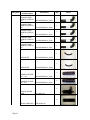
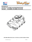
MERCURY MARAUDER SUPERCHARGER SYSTEM INSTALLATION INSTRUCTIONS 2003 & 2004 MODEL-YEAR 3241 South Gulley Road, Dearborn Michigan 48124 WWW.TRILOGYMOTORSPORTS.COM MARCH 2011 V2.1.1 INDEX 1. 2. 3. 4. 5. 6. 7. NOTICE ......................................................................................................................... 2 WARRANTY AND THANK YOU LETTER. .............................................................. 3 INSTALLATION INSTRUCTIONS ............................................................................. 4 TOOLS & PARTS LIST ................................................................................................ 7 ENGINE DISASSEMBLY INSTRUCTIONS ............................................................. 17 SUPERCHARGER ASSEMBLY INSTRUCTIONS .................................................. 48 FINAL CHECK .......................................................................................................... 141 Page 1 1. NOTICE This product is protected by state common law, copyright and/or patent. All legal rights therein are reserved. The design, layout, dimensions, geometry, and engineering features shown in this product are the exclusive property of Trilogy Motorsports. This product may not be copied or duplicated in whole or part, abstractly or fundamentally, intentionally or fortuitously, nor shall any design, dimension, or other information be incorporated into any product or apparatus without prior written consent of Trilogy Motorsports. Page 2 2. WARRANTY AND THANK YOU LETTER There is a 1-Year Limited Warranty included with the purchase of your Marauder Supercharger kit; covering the component parts that make up the supercharger unit only (no labor is covered under this warranty). However, to take advantage of this program you must fill out the Warranty Registration Form and mail it back to Trilogy Motorsports within 30 days from the time of purchase so that we can activate your warranty. Thank you for being our customer. We sincerely hope that your new supercharger will give you thousands of miles of enjoyment! Page 3 3. INSTALLATION INSTRUCTIONS Before beginning this installation, please read through this entire instruction booklet. Trilogy Motorsports supercharger systems are performance improving devices. In most cases, increases in torque of 35% to 40% and horsepower of between 45% and 50% can be expected with the boost levels specified by Trilogy Motorsports. This product is intended for use on healthy, well-maintained engines. Installation on a worn-out or damaged engine is not recommended and may result in failure of the engine as well as the supercharger. Trilogy Motorsports is not responsible for engine damage. Installation on new vehicles will not harm or adversely affect the break-in period so long as factory break-in procedures are followed. For best performance and continued durability, please take note of the following key points: 3.1. Use only premium grade fuel 92 octane or higher (R+M/2). 3.2. The engine must have stock compression ratio. 3.3. If the engine has been modified in any way, check with Trilogy Motorsports prior to using this product. 3.4. Always listen for any sign of detonation (knocking sound) and discontinue hard use (no boost) until problem is resolved. Trilogy Motorsports is not responsible for engine damages or failure. 3.5. Perform oil and filter change upon completion of this installation and prior to testdriving your vehicle. Thereafter, always use a high grade SF rated engine oil or a high quality synthetic, and change the oil and filter at least every 3,000 miles. Page 4 IMPORTANT NOTICE Trilogy Motorsports Mercury Marauder Supercharger Kit Tuning Notes Congratulations on your purchase of the highest-quality supercharger kit available for the Mercury Marauder. Your kit includes a custom calibrated tune for the factory ECM that was developed by the experts at Alternative Auto Performance. The calibration accommodates for the extra power the supercharger provides and makes the necessary changes in air/fuel ratio and ignition timing to safely deliver impressive power. Improvements to various transmission operations are also made to take advantage of the increased power and torque. This calibration provides stock-like drivability and reliability with the Trilogy Motorsports Mercury Marauder supercharger kit. The tune must be installed using and SCT handheld tuner. The SCT tuner is not included with the kit. If you currently own and SCT tuner for your Marauder you can ship it to us to have the calibration flashed to your unit. If you do not own a SCT tuner you may purchase one from us and it will be shipped preprogrammed with your kit. The engine calibration is designed to SAFELY deliver 385 – 390 RWHP (as measured on a DynoJet chassis dynamometer @ 591 feet above sea level) utilizing the kit’s standard 9.5 PSI boost output and 92 octane, or better gasoline. During the calibration’s development, additional horsepower was relatively easy to find while on the dyno through more aggressive timing and A/F ratios. However, real-world load and wind resistance in drag strip and high-speed testing confirmed that power above the standard calibration put the engine into what Alternative Auto deemed an overly aggressive tune that didn’t leave a large enough margin-for-error. A DynoJet chassis dynamometer is an invaluable tuning aid, but cannot duplicate the exact conditions a vehicle will encounter while on pavement. It is extremely important to note that regional fuel quality and air density can vary greatly. For this reason, the final engine calibration provided with the Trilogy Motorsports kit is conservative meaning it is safe for the variety of conditions you will encounter while driving and racing your supercharged Marauder. If you have any specific questions about how to safely and reliably increase the power output with this kit, please contact Alternative Auto Performance at 586.463.0010. www.trilogymotorsports.com Page 5 (313) 336-6135 www.alternativeauto.com (586) 463-0010 Page 6 4. TOOLS & PARTS LIST The following list details the tools and supplies that are needed to build your kit. The “helpful” items are not crucial to the assembly but make life easier. 4.1. REQUIRED TOOLS Deep well socket for some common metric sizes are helpful Side wrench metric: 8, 10, 12, 13, 14 Socket metric: 8, 10, 13, 14 Allen wrench metric: 6, 8, 10 Adjustable wrench Pliers Flat screwdrivers Drill and Drill Bits Wire stripper and crimping tool Hydraulic floor jack Jack stands Knife Torque wrench Eye protection Gloves Grinder 4.2. REQUIRED SUPPLIES Page 7 Coolant Spark Plugs Duct Tape, Teflon Tape, and Electrical Tape Acetone or Carburetor Cleaner Blue and Red Loctite (for threads) WD 40 – Spray SCT X3 Flash Tuner 4.3. PARTS LIST Please make sure you have all the parts listed below prior to start with your supercharger installation. If you are missing any of the components listed below, please contact us immediately. Please also note that there are some parts needed for the supercharger installation and that are not included in this list; these parts will be used from the stock Marauder. LIST OF SUPPLIED PARTS Subsystem Throttle body Component Name and Description ADAPTER THROTTLE BODY ACCEL/CRUISE CABLE BRACKET Part Number Qty 1 4W33-030104-004-A1 1 4W33-031800-002-B1 1 SPACER THROTTLE BODY 4W33-030104-002-C1 PCV TEE CONNECTOR - Size 5/8x5/8x5/8 4W33-6C324-C_PIA1 FUEL VAPOR HOSE EXTENSION SIZE ID 3/8” 4W33-6C324-C_PIA3 HOSE-IDLE AIR CONTROL (IAC) SIZE ID 1/2” 1 1 1 4W33-6C324-C_PIA2 Intake manifold 1 INLET DUCT SUPERCHARGER UNIT 4W33-030104-003-A 1 4W33-030407-001-B 1 LOWER INTAKE MANIFOLD Page 8 2R3Z-9424-BB Picture Subsystem Component Name and Description Part Number Qty 1 INTERCOOLER CORE 2R3Z-6K775-BA 1 OUTLET PLATE ACTUATOR VACUUM HOSE Size ID ¼” ACTUATOR VACUUM HOSE Size ID 3/8” 4W33-030104-001-E1 1 4W33-030407-001-A_PIA2 1 4W33-030407-001-A_PIA3 TEE HOSE CONNECTOR - Size 3/8x1/4x3/8” 4W33-030407-001-A_PIA4 1 EGR system 1 EGR Tube 4W33-9D477-A PCV System 1 PCV TUBE 4W33-6C324-B1 1 PCV HOSE ASSEMBLY IC Cooling system COOLING HOSE (HOSE # 1) SIZE ID 5/8” 4W33-6C324-A 1 4W33-030304-001-A_PIA1 COOLING HOSE (HOSE # 2) SIZE ID 5/8” 4W33-030304-001-A_PIA2 Page 9 1 Picture Subsystem Component Name and Description Part Number Qty COOLING HOSE (HOSE # 3) SIZE ID 3/4” 4W33-030304-001-A_PIA3 1 COOLING HOSE (HOSE # 4) SIZE ID 3/4” 4W33-030304-001-A_PIA4 1 COOLING HOSE (HOSE # 5) SIZE ID 3/4” 4W33-030304-001-A_PIA5 1 COOLING HOSE (HOSE # 6) SIZE ID 3/4” 4W33-030304-001-A_PIA6 1 COOLING HOSE (HOSE # 7) SIZE ID 3/4” 4W33-030304-001-A_PIA7 1 1 CONVOLUTE 4W33-030304-001-A_PIA10 1 CONVOLUTE 4W33-030304-001-A_PIA11 1 CONNECTOR SIZE 3/4" – 3/4" 4W33-030304-001-A_PIA8 CONNECTOR SIZE 5/8” – 3/4" 4W33-030304-001-A_PIA9 2 1 ELECTR. WATER PUMP F8YH-8501-AA 1 FRONT RADIATOR 2R3Z-8K226-AA Page 10 Picture Subsystem Component Name and Description Part Number Qty 1 WATER PUMP MOUNT. BRACKET 4W33-8N500-A 2 RADIATOR BRACKET 4W33-030302-001-A1 2 RADIATOR BRACKET TOP 4W33-030302-002-A1 2 J-CLIP M6-1.0 FOLDOVER Motormite_45411 1 IC RESERVOIR BRACKET 4W33-030302-003-B2 1 COOLANT RESERVOIR 3R3Z-8A080-AB 1 WATER INLET ADAPTER 2R3Z-9N491-HA 1 GASKET WATER INLET ADAPTER 2R3Z-9L439-BA 2 WATER ADAPTER TUBES Page 11 2R3Z-9L442-AA Picture Subsystem Component Name and Description Part Number Qty 4 WATER INLET ADAPTER O-RINGS N802927S Engine cooling system 4W33-030304-001-C2 and MARAUDER CROSSOVER TUBE 4W33-030304-001-C1 2 O-RINGS 391533S100 1 HEATER HOSE ELBOW 4W33-030304-001-C_PIA1 Engine heating system 1 HEATER WTR OUTLET TUBE F8ZZ-18B402-BA 1 HOSE CONNECTOR 5/8"-5/8" 4W33-030304-001_PIA5 1 Page 12 CONVOLUTE 4W33-030304-002_PIA7 HEATER HOSE # 8 – SIZE ID 5/8" 4W33-030304-002-A_PIA8 HEATER HOSE # 9 – SIZE ID 5/8" 4W33-030304-002-A_PIA9 1 1 Picture Subsystem Component Name and Description Part Number Qty FEAD system 1 CRANK BLOWER PULLEY 4W33-030504-005-B1 IDLER PULLEY RIBBED F5RZ-6C348-A 1 1 BRACKET TENSIONER 4W33-030504-F_ASY 1 TENSIONER 2R3Z-6B209-AA ALTERNATOR BRACKET (pre-assembled with 4W33-030504-002- 4W33-030504-002-C2 A2-W) 1 IDLER PULLEY FLAT (pre-assembled with 4W33-030504-002C2) 4W33-030504-002-B1 1 1 DRIVE BELT - 6 RIBBED 4W33-030504-006-A1 1 DRIVE BELT – 8 RIBBED 4W33-030504-007-A1 Electrical wiring system 1 WATER PUMP HARNESS Page 13 4W33-180101-002-A Picture Subsystem Component Name and Description ALTERNATOR HARNESS EXTENSION Part Number 1 4W33-180101-001-A 1 RED T-TAP CONNECTOR T-250R YELLOW T-TAP CONNECTOR T-250Y HARNESS EXTENSION SUPPLIES 1 1 SET 4W33-180101-001-A_PIA1 ALTERNATOR PULLEY (replace the existing pulley on alternator with this supplied pulley) F5OY-10344-F NUT FOR ALTERNATOR PULLEY Qty 1 1 N807805-S36B 1 IAT2 SENSOR F6SZ-12A697-A 1 IAT2 WIRING HARNESS 4W33-180101-004-A1 Fuel Injection system 8 FUEL INJECTORS FUEL PUMP AMPLIFIER + HARNESS Page 14 2R3Z-9F593-BA 1 KB89067 Picture Subsystem Component Name and Description Part Number Qty Other systems 1 BOOST GAGE GAGE FITTING COUPLING 4301 1 28-058L 1 GAGE FITTING – PIPE 28-140 GAGE FITTING TEE 28-245 1 1 SILICONE SEALANT DECAL MARAUDER S/C 4W33-010800-001-A DECAL TRILOGY MOTORSPORTS 3 2 4W33-010800-002-A 1 HORN BRACKET Page 15 4W33-130601-001-A1 Picture 4.4. LIST OF SUPPLIED FASTENERS Component Bolt Descr. Water Pump Mount. Brkt Water Pump relay Water Pump fuse holder Blower Water Inlet Adapter Lower Intake Manifold Idler Pulley Flat Idler Pulley Ribbed Alternator Bracket Crank Blower Pulley Bracket Tensioner Bracket Tensioner + Tensioner Inlet Duct + Blower Outlet Plate IC Reservoir Bracket 2 3/4 in M6x 1.0 2 16 Self tapping #8 1 1/2 in Self tapping #8 1 1/2 in M8 x 1.25 Socket Hexagon Head 6 30 M6x1 3 35 M6x1 1 60 M8x1.25 10 30 M8x1.25 1 20 M8 / O.D. 23 1 M8x1.25 1 20 M8 / O.D. 23 Idler Pulley Ribbed to engine 1 cover M8x1.25 M8x1.25 Socket Hexagon Head 2 50 M8 / O.D. 23 2 Alternator to alt brkt M10x 1.5 Socket Hexagon Head 1 3 Bracket attached to fender inner Lock M8 Lower intake manifold to outlet plate 110 M8 2 M8 / O.D. 16 50 M8x1.25 Socket Hexagon Head 3 140 M8x1.25 3 30 M8x1.25 3 25 5 2 Alt brkt to engine cover Lock M10 3 Flat M10 3 M8x1.2 M6x1.0 Socket Hexagon Head 10 16 2 Lock M6 10 Outlet Plate to IC core Flat M6 10 1 M8x1.25 25 Acorn 1 Lock M8 1 M8x1.25 3 M8x1.25 30 Acorn 1 Lock M8 1 M6x1.0 4 16 M6 2 Lock M6 2 Flat M6 4 4 Lock M8 2 M8x1.25 M6x1.0 Clamp Size # 4 4W33-6C324A_FST1 Clamp Size # 10 4W33-030304001-A_FST1 Clamp Size # 12 4W33-030304001-A_FST2 Clamp Size # 20 4W33-030304001-C_FST1 Page 16 6 Blower to outlet plate Water Inlet Adapter to Lower Intake Manifold 4 20 M8 M8 / O.D. 23 Crossover Tube Comment Pc Self tapping #14 Spacer Throttle Body + Inlet M8x1.25 Duct Radiator Bracket Nut Washer Pc L (mm) Descr. Pc Descr. 2 4 16 1 10 10 2 Crossover Tube 5. ENGINE DISASSEMBLING INSTRUCTIONS a) Disconnect the battery; b) Drain the engine cooling system; c) Remove the Degas Bottle supply hose; Page 17 d) Remove the overflow hose; e) Remove the bolt and the Degas Bottle; Page 18 f) Unscrew powersteering reservoir (but leave all the hoses connected), and push it to the side to make enough room; Page 19 g) Remove the pin-type retainers and remove the radiator sight shield; h) Disconnect the connector of the Cooling Fan Motor; Page 20 i) Remove the two bolts and the fan blade, fan motor and the fan shroud assembly; j) Remove the Upper Radiator Hose from the radiator (keep it available for later use); Page 21 k) Remove Front Facia Grill; Page 22 l) Remove the crankcase ventilation hose, clamps, and remove the Zip Tube (air cleaner outlet pipe); m) Remove the accelerator control splash shield; Page 23 n) Remove the accelerator cable, the speed control cable and the return spring; o) Disconnect the fuel vapor hose; Page 24 p) Remove the accelerator control cable from the bracket; q) Remove the speed control cable from the bracket; Page 25 r) Disconnect the vacuum hose; s) Remove the bolt, disconnect the acceleration control cables and position them aside; Page 26 t) Remove bolt and the bracket; Page 27 u) Remove the exhaust gas recirculation (EGR) Tube completely from EGR Valve and Exhaust Manifold (use adjustable wrench); EGR Valve and EGR Tube Page 28 v) Disconnect the throttle position (TP) sensor and the idle air control (AIC) sensor electrical connectors; w) Disconnect the positive crankcase ventilation (PCV) Tube; Page 29 x) Remove the EGR system module electrical connector; y) Remove EGR Valve; Page 30 z) Disconnect the vacuum hoses and the positive crankcase ventilation (PCV) coolant hoses; Page 31 aa) Remove the Upper Intake Manifold assembly bolts in the sequence shown. Remove the intake manifold assembly; Page 32 Engine without Upper Intake Manifold Page 33 bb) Remove Accessory Drive Belt; Accessory belt tensioner Page 34 cc) Remove Upper Bracket on Alternator; Crossover Tube and Alternator without bracket Page 35 dd) Disconnect wiring harness from Water Temperature Sensors on Crossover Tube; Connectors from Engine Coolant Temperature Sensors ee) Disconnect the coolant hoses; Page 36 ff) Disconnect the coolant hoses, the electrical connectors, and the wiring harness retainer; Page 37 gg) Remove the Crossover Tube; Page 38 hh) Remove the 2 bolts and the Alternator; Alternator retension bolts Page 39 ii) Disconnect the electrical connector and the vacuum hose from the fuel pressure sensor; jj) Separate the wiring harness from the fuel injection supply manifold studs in four places; Page 40 kk) Disconnect the eight fuel injector electrical connectors; Page 41 ll) Remove Fuel Rail and Fuel Injectors (and leave fuel rail on right side of the car) from Lower Intake Manifold. Before removing, release pressure from Fuel Rail. DO NOT DISCONNECT FUEL RAIL FROM FUEL LINES. Fuel rail retension studs Page 42 mm) Remove the ten bolts in the sequence shown, and raise the Lower Intake Manifold Slightly (save bolts and gaskets for later use); 4 8 3 10 7 9 6 5 2 1 Lower Intake Manifold (Crossover Tube removed) nn) Disconnect the Engine wiring harness from the rear of the lower intake manifold and remove the manifold; Page 43 oo) Remove Knock Sensor(s) from Engine Valley, but leave knock sensor(s) connected to engine wiring harness, and move somewhere close to the firewall for now. Later the sensor(s) will be bolted on the back of the cylinder head. Knock Sensor Page 44 pp) Remove the Flat Idler Pulley from the Front Engine Cover; Page 45 qq) Remove the Water Heat Tube from the Water Pump (unscrew bolt on the back of right cylinder head which is holding the engine ground wire and the Water Heat Tube); Water Heat Tube with stud rr) Cover the inlet ports with washing (duct) tape; ss) Cover the water pump outlet with washing (duct) tape; Page 46 tt) Remove the 3 bolts on the Front Engine Cover (these bolts will be replaced later with bolts for holding the alternator and the Tensioner Bracket). Remove the 3 bolts of this locations Page 47 6. SUPERCHARGER ASSEMBLYING INSTRUCTIONS 6.1. SPARK PLUGS a) Re-gap spark plugs to 0.032”. Use of one heat-range colder spark plugs (Motorcraft P/N: AWSF-22C or NGK TR6 or Champion RS9YC) is optional. Page 48 6.2. FUEL PUMP AMPLIFIER INSTALLATION Parts: Fuel Pump Amplifier + harness a) Open the trunk and locate, on the left side of the end of the trunk, the Fuel Pump Harness. b) Pick a spot in the trunk where you want the fuel pump amplifier (Boost-APump) module box to be mounted. c) Mount the fuel pump amplifier (Boost-A-Pump) module box in the trunk. Fuel Pump Harness d) Open the Fuel Pump Harness. e) Locate the smaller harness within that. f) Remove the black vinyl rapping and the aluminum shield. Page 49 g) Locate within the smaller harness the Pink/Black “HOT” (12 Volt Positive +) wire going to the pump. h) To the left of the Pink/Black wire is the supply to be used for the Boost-aPump. And to the right is what feeds the fuel pump. Goes to supply Goes to Pump Page 50 i) Cut the Pink/Black “HOT” (12 Volt Positive +) wire going to the pump, and connect the wiring harness of the Boost-A-Pump as shown on the following picture Connect the red wire to the Pink/Black wire going to the pump Connect this black wire to Ground “S” black wire to be routed to the Boost Gage Connect this pink wire to the Pink/Black wire going to pump supply Page 51 j) Mount the controller in the trunk (the initial set for the controller should be put to 10). Page 52 k) Route the “S” black wire from the Boost-A-Pump to the interior of the car, passing behind the left back seat, then passing under the LH scuff plates, until front console (it will be connected later to the Boost Gage). Page 53 6.3. BOOST GAGE INSTALLATION Attention: We suggest starting routing of boost gage line from interior to outside. Apply the Teflon tape (or thread seal) on to all pipe thread connections. Parts: Boost Gage (4301) Coupling (P/N 203200) Pipe fitting (P/N 213210) Tee fitting (P/N 227200) a) Remove the auxiliary gauge cluster; b) Remove one on the OEM gages in the auxiliary gauge cluster (whichever you consider less important than the other). We recommend removing the voltmeter gage; We recommend installing the Boost Gage here c) Cut the black wire and the red/yellow wire that were connected to the voltmeter gage (if this is the gage that you removed) and isolate them with electrical tape or shrink tubing; Page 54 d) In order to fit boost gage with fittings in floor console, you need to cut out a plastic flange. Make the cut on the floor console according to the following picture; Attention: be careful so that you don’t cut the wires nearby. Floor Console: before and after cutting Page 55 e) Install coupling (P/N 203200) on boost gage. Then assemble with pipe fitting (P/N 213210), Tee fitting (P/N 227200), vacuum/pressure switch (boost-a-pump), boost line fitting as shown on the following picture. Do not forget to apply Teflon tape on threads. Connect Boost Line f) Connect the “S” black wire from the Boost-A-Pump on the back fitting of the Boost Gage (see picture on the section of Boost-A-Pump installation). g) Install Boost gage. Start routing of boost gage line from interior to outside. Connect the gages in the connectors of the auxiliary gauge cluster; h) Reinstall the auxiliary gauge cluster Page 56 i) Then route hose from Boost Gage through the grommet next to the gas pedal (you may need to punch a hole through the grommet); Page 57 6.4. KNOCK SENSOR BOSS REMOVAL Parts: LOWER INTAKE MANIFOLD (P/N 2R3Z-9424-BB) (this part is used here for clearance check and will be installed later). a) Remove the gaskets and tape off the intake ports of the cylinder block. And also the ports on the engine cover. b) Grind off knock sensor bosses from Cylinder Block. Grind approximately 3/16 in, and then test to see if it’s enough (remove the gaskets on cylinder head and place the Lower Intake Manifold supplied by Trilogy, and try to see if it can move freely horizontally, without rocking; the bosses should not interfere with the Lower Intake Manifold). If you have to grind more, do so, but do not exceed 1/2 in, and be careful not to grind the engine block reinforcements; Grind approximately3/16 in Knock sensor bosses after grinding c) Clean any shaves. Page 58 6.5. HEATER WATER TUBE INSTALLATION Parts: HEATER OUTLET TUBE (P/N F8ZZ-18B402-BA) HEATER HOSE # 9 – SIZE ID 5/8" CLAMPS SIZE # 10 HOSE CONNECTOR 5/8"-5/8" 1 Bolt M6x1.0x16 a) Before the installation of the heater tube, inspect O-ring on water pump outlet fitting. If O-ring has visible signs of the wear, replace it (not supplied in the kit). b) Lubricate O-ring with silicone spray. c) Insert Heater Water Outlet Tube (P/N F8ZZ-18B402-BA) on water pump outlet fitting. Install tube carefully to avoid damaging of the O-ring. Install Tube here Page 59 d) Tighten the heater tube to cylinder head with supplied M6x16mm bolt and reuse stud that retained original heater tube. Page 60 e) Bolt the right bank knock sensor to the cylinder head at the spot where was previously the stud that retained ground wire and original heater outlet tube. Reuse M8 bolt that retained original Alternator bracket. Bolt Left bank knock sensors (if equipped) to the LH cylinder head as indicated on the picture below. Use M8 x 35 mm bolt. Orient the knock sensor wire so it does not rub against the any sharp edges. f) Retain the ground wire to the cylinder head with M6 bolt (reuse M6 bolt from engine disassembling). Ground wire Knock sensor Right hand side Page 61 Location of knock sensor on Left hand side g) To install heater hose extension, use supplied heater hose # 9, 5/8” – 5/8” connector, convolute and 4 clamps of size # 10. h) i) Install 5/8” – 5/8” connector on heater hose # 9. j) Disconnect Outlet Heater Hose that is connected to heater unit. Page 62 k) Assemble Outlet Heater Hose with heater hose #9. Slide a convolute over the hoses and hose connector. Cut out the opening in convolute for clamps. l) Connect the Outlet heater hose to heater hose unit. Use clamp size #10. m) Connect the heater hose # 9 to heater outlet tube. Page 63 6.6. LOWER INTAKE MANIFOLD INSTALLATION Parts: LOWER INTAKE MANIFOLD (P/N 2R3Z-9424-BB) PCV HOSE ASSEMBLY (P/N: 4W33-6C324-A) Clamp Size # 4 (P/N: 4W33-6C324-A_FST1) a) Check if original intake manifold gaskets on cylinder heads are OK and if so use them. If not replace with new gaskets. Page 64 b) Install Clamp Size # 4 to retain the PCV Hose Assembly (P/N: 4W336C324-A) to PCV hose fitting on the Lower Intake Manifold. The screw of the clamp must be between the hose and the Lower Intake Manifold, so that it won’t interfere when installing on Engine Block PCV Hose Assembly plugged to Lower Intake Manifold c) Install the Lower Intake Manifold. Note: PCV hose should be routed between wiring harness and heater hose # 9. To tighten the manifold, reuse the bolts that held the original lower intake manifold. Installation of Lower Intake Manifold Page 65 d) Tighten intake manifold fasteners in the sequence shown 10 Nm (89 lb-in) 9 5 10 Page 66 1 6 7 2 3 8 4 6.7. FUEL INJECTORS AND FUEL RAIL INSTALLATION Parts: FUEL INJECTORS (2R3Z-9F593-BA) a) Install new injectors supplied in the kit; Page 67 b) Install fuel rail with original bolts, however do NOT tight the fuel rail to lower intake manifold yet. You will need a slack in fuel rail when installing the Supercharger Intake assembly. Page 68 c) Install back the clips that retained the old fuel injectors on the fuel rail; Page 69 6.8. SUPERCHARGER INTAKE ASSEMBLY Attention: Supercharger Intake assembly consists of Supercharger unit (P/N 4W33-030407001-B), Outlet Plate (P/N 4W33-030104-001-C1), IAT2 Sensor (F6SZ-12A697A), IAT Connector (3U2Z-14S411-JUA), Intercooler Core (P/N 2R3Z-6K775BA) and Inlet Duct (P/N 4W33-030104-003-A). Whole assembly is quite heavy and you will need extra pair of hands to help you drop the assembly into lower intake manifold. Handle with care and avoid slamming into vulnerable parts like Intercooler Core or Bypass vacuum actuator (small plastic vessel attached to supercharger unit). Under NO circumstances handle the supercharger unit or Supercharger Intake assembly by holding Bypass vacuum actuator. This can cause severe damage to actuator. Parts: OUTLET PLATE (P/N 4W33-030104-001-C1) IAT2 SENSOR (F6SZ-12A697-A) IAT CONNECTOR (3U2Z-14S411-JUA) INTERCOOLER CORE (P/N 2R3Z-6K775-BA) SUPERCHARGER UNIT (P/N 4W33-030407-001-B) INLET DUCT (P/N 4W33-030104-003-A) Sealant 10 Bolts M6x1.0x16 Socket Hex Head, 10 M6 lock washers, 10 M6 flat washers 6 Bolts M8x1.25x30 Socket Hex Head, 6 M8 lock washers 3 Bolts M8x1.25x25, 2 M8 Acorn Nuts, 2 M8 lock washers 10 Bolts M8x1.25x30 Page 70 a) Assemble Outlet Plate and IC Core together. Apply silicone sealant on mating faces (approximately 1/8” of height of sealant across the entire perimeter). Use 10 M6x16 socket head bolts with M6 lock and flat washers. Apply blue Loctite in all the bolts and tighten with 106 in*lb. Attaching blower to the outlet plate + IC core unit Page 71 b) Apply silicone sealant on the face of Blower outlet port (approximately 1/8” of height of sealant across the entire perimeter), as shown on the following picture. Silicon seal on blower Page 72 c) Bolt the supercharger unit (blower) to Outlet plate with 6 M8x30 mm Socket Hex head bolts and M8 lock washers, using a torque of 20 to 22 ft*lb. Using long socket (3/4”), screw IAT2 Sensor to Outlet Plate. IAT2 Sensor Page 73 d) Apply silicone sealant on the face of the blower inlet port (approximately 1/8” of height of sealant across the entire perimeter). Page 74 e) Bolt the Inlet Duct to the blower with 3 M8x25mm bolts, and 2 M8 nuts with nylon lock. Back view of Inlet Duct assembled with Blower Front view of Inlet Duct assembled with Blower Page 75 f) Apply silicone sealant on mating face of Lower intake manifold (approximately 1/8” of height of sealant across the entire perimeter). Page 76 g) Carefully install Supercharger Intake Assembly in Lower Intake manifold. Note: Bolt # 8 (see picture after 2 pages for correct bolt numbering) must be started before the blower assembly is installed on lower intake manifold Page 77 h) Install the Compression Fitting of the Boost Gage on Outlet Plate (Apply Teflon tape or thread seal). Then connect the Boost Gage line to the fitting on back of the Outlet Plate that seats on the intake manifold (DO NOT OVERTIGHT THE COMPRESSION FITTING); Page 78 i) Tighten the Assembly to lower intake manifold with 10 M8x30mm bolts. Note: Bolts # 9 and # 10 will be removed later on, when installing Crossover tubes 4W33-030304-001-C2 and 4W33-030304-001-C1. 29 Nm (264 lb-in) 9 5 1 7 3 4 10 6 2 8 Front of the vehicle Page 79 6.9. EGR Parts: EGR Tube (4W33-9D477-A) a) Install EGR valve on EGR flange of Inlet Duct. Check for any wear or mechanical damage to EGR gasket and replace if necessary with new EGR gasket. Page 80 b) Carefully slide EGR tube, supplied in the kit, between a back of the engine and firewall. Install the EGR tube on exhaust manifold and EGR valve. Start the fittings on both ends first and tight firmly only after you make sure that EGR tube aligns properly on both ends. Page 81 c) Connect the eight fuel injector electrical connectors. d) Position the fuel charging wiring and connect to the fuel injection supply manifold in four places Page 82 6.10. ACCELERATOR CABLE AND CRUISE CONTROL CABLE Parts: Accelerator/Cruise Cable Bracket (P/N 4W33-031800-002-B1) a) Inspect original accelerator and cruise control cables for sign of wear. If necessary, replace. b) Snap accelerator cable and cruise control cable on Accelerator Cable Bracket. Accelerator Cable Cruise Control Cable Accelerator Cable Bracket Page 83 c) To check for the clearance between cruise control cable and Inlet Duct (P/N 4W33-030104-003-A), try to install Accelerator/Cruise Cable Bracket with cables on Inlet Duct using 2 M8 bolts. If you have a difficulty to get bolts thru the holes in the Accelerator/Cruise Bracket and Inlet Duct, you may need to cut a little bit of material from flange on the plastic swivel on the cruise control cable. Note: Be careful not to damage cable linkage. You may need to cut a little of material from flange on the plastic swivel d) Remove the Accelerator/Cruise Cable Bracket from Inlet Duct (it will be installed later). Page 84 6.11. ADAPTER THROTTLE BODY AND SPACER THROTTLE BODY INSTALLATION Parts: Adapter-Throttle Body (P/N 4W33-030104-004-A1) Spacer Throttle Body (P/N 4W33-030104-002-C1) 1 Bolt M8x1.25x25, 3 Bolts M8x1.25x30, 2 M8x1.25 Acorn Nuts, 2 M8 lock washers a) Apply silicone sealant on both sides of Adapter Throttle Body. b) Bolt together Throttle Body, Adapter Throttle Body and Spacer Throttle Body with 4 M6 bolts that are reused. Make sure that components are assembled correctly (see picture). Page 85 c) Apply silicone sealant (approximately 1/8” of height of sealant across the entire perimeter) on open face of Spacer Throttle body. Page 86 d) Install Spacer Throttle body on Inlet Duct. Use 1 Bolt M8x25mm for the RH side at the bottom of the assembly and 3 Bolts M8x30mm for the other holes. Use 2 Acorn Nuts with 2 lock washers: 1 at the RH upper position, and 1 at the LH bottom position. NOTE: Assemble the Accelerator/Cruise Cable Bracket with Cables on Inlet Duct at the same time as Spacer Throttle Body. M8x30 mm Bolt, Acorn nut and Lock Washer M8x25mm Bolt M8x30mm Bolt M8x30 mm Bolt, Acorn nut and Lock Washer Page 87 e) Install throttle and cruise control cable on throttle body lever. And install the return spring (Attached to Accelerator/Cruise Cable Bracket). Page 88 f) Install Idle Air Control (AIC) Valve on the Spacer Throttle Body. Check the gasket and replace if necessary. Reuse the original M6 bolts. Page 89 6.12. Parts: INTERCOOLER INLET ADAPTOR INSTALLATION Water Adapter Tubes (P/N 2R3Z-9L442-AA) Water Inlet Adapter O-rings (P/N N802927S) Water Inlet Adapter (P/N 2R3Z-9N491-HA) Gasket Water Inlet Adapter (P/N 2R3Z-9L439-BA) 1 Bolt M6x1.0x60, 3 Bolts M6x1.0x35 a) Install Water Inlet Adapter O-rings on Water Adaptor Tubes. Lubricate O-rings with silicone spray or engine oil. b) Install Water Adaptor Tubes. Page 90 c) Install Intercooler Water Inlet Adapter with Gasket Water Inlet Adapter and tighten with 4 bolts, using torque of 106 in*lb (use blue Loctite). Tighten 4 bolts Page 91 6.13. ACCESSORY BELT INSTALLATION Attention: Due to the packaging of the Supercharger, the alternator has to be moved away from its original location to clear the room for supercharger nose. This will require using a new 6-groove accessory belt, which is also supplied in the kit. Supercharger unit is driven by additional 8-groove belt. Note: substitute the old alternator pulley with the one supplied by Trilogy (along with nut). Parts: Drive Belt – 6 Ribbed Alternator Bracket + Idler Pulley Flat (P/N 4W33-030504-002-C2 + 4W33-030504002-B1) Idler Pulley Ribbed (P/N F5RZ-6C348-A) Alternator Pulley + Nut (P/N F5OY-10344-F, N807805-S36B) 1 Bolt M8x1.25x20, 1 M8/O.D. 23 flat washer (pre-assembled) 1 Bolt M8x1.25x110 Socket Hex Head, 2 M8 nuts, 3 M8 lock washers 2 Bolts M8x1.25x50, 2 M8/O.D. 23 flat washers 1 Bolt M8x1.25x20, 1 M8/O.D. 23 flat washer Page 92 a) Routing of a new 6-ribbed serpentine belt is shown on the following picture. 6-RIBBED BELT IDLER PULLEY RIBBED WATER PUMP PULLEY ALTERNATOR IDLER PULLEY FLAT IDLER PULLEY ALTERNATOR BRACKET TENSIONER A/C COMPRESSOR Page 93 CRANKSHAFT PULLEY POWER STEERING PUMP PULLEY b) Routing of a new 8-ribbed supercharger belt is shown on the following picture. BLOWER PULLEY 8-RIBBED BELT TENSIONER CRANK BLOWER PULLEY Page 94 c) Install Idler Pulley Ribbed. Tighten with M8x20mm bolt and washer (O.D. 23mm). IDLER PULLEY RIBBED d) Install Alternator Bracket assembly using M8x110mm bolt, 2 M8 nuts and 3 M8 lock washers. Route the belt as shown on the picture. Page 95 e) Alternator pulley replacement: The original alternator pulley must be replaced with the new alternator pulley (part number F5OY-10344-F and nut) which is included with your kit. Since a special tool is required we recommend allowing your local auto parts store or repair facility change the pulley for you. f) Install Alternator (with the replaced pulley and nut). Note: make sure to use M8 washers with O.D. 23 mm and proper length of bolts, M8x50mm. g) Install 6-ribbed belt. Page 96 Page 97 6.14. INTERCOOLER CIRCUIT and ENGINE COOLING Attention: Hoses as installed must not kink and should not rest on any sharp edges of surrounding parts. All hoses with ID 5/8” must be retained with hose clamps size # 10, and all hoses with ID 3/4" must be retained with clamps size # 12. Parts: Marauder Crossover Tube RH (P/N 4W33-030304-001-C1) Marauder Crossover Tube LH (P/N 4W33-030304-001-C2) Heater Hose Elbow (P/N 4W33-030304-001-C_PIA1) IC Reservoir Bracket (P/N 4W33-030302-003-B2) Coolant Reservoir (P/N 3R3Z-8A080-AB) Connector 3/4" – 3/4" Connector 5/8” – 3/4" Horn Bracket (P/N 4W33-130601-001-A1) J-Clip M6-1.0 Foldover (P/N Motormite_ 45411) Front Radiator (P/N 2R3Z-8K226-AA) Radiator Bracket (P/N 4W33-030302-001-A1) Radiator Bracket Top (P/N 4W33-030302-002-A1) Water Pump Mount Bracket (P/N 4W33-8N500-A) Electrical Water Pump (P/N F8YH-8501-AA) Clamps size # 10 Clamps size # 12 Clamps size # 20 2 Bolts M6x1.0x16 4 Bolts M8x1.25x20, 4 M8 Nuts, 4 M8 O.D. 23mm Flat washers, 2 M8 Lock washers 2 M6-1.0 J-clips 4 Bolts M6x1.0x16, 4 M6 Nuts, 6 M6 flat washers 2 #14 self tapping screws 2 Bolts M6x1.0x16 Steel braided hoses Note: If your kit is equipped with additional set of steel braided hoses, those will replace following “black” rubber hose: Hose #1 (P/N: 4W33-030304-001-A_PIA1) Hose #2 (P/N: 4W33-030304-001-A_PIA2) Hose #3 (P/N: 4W33-030304-001-A_PIA3) Hose #4 (P/N: 4W33-030304-001-A_PIA4) Hose #8 (P/N: 4W33-030304-002-A_PIA8) All steel braided hoses come pre-assembled with hose clamps (size 10 and size 12) and Econo Fit clamps (size 14 and size 16). Prior to the installation of the hoses, loose the bolt on the clamps so the hose can be installed easily. Before tightening the clamps, orient the clamp in such way so it does not protrude to any surrounding hoses or any part (i.e. A/C line) that could cause damage to. After the installation of steel braided hose you may wish to cut with razor excessive black tape on ends of the braided hose. Page 98 Intercooler coolant circuit sketch 1: IC Core Reservoir IC Pump Radiator Page 99 Intercooler coolant circuit sketch 2: Connector 5/8" - 3/4" Hose #3 I.D. 3/4" Hose #2 I.D. 5/8" Outlet (top) Reservoir IC Core Inlet (bottom) Hose #4 I.D. 3/4" Hose #1 I.D. 5/8" Connector 3/4" - 3/4" Connector 5/8" - 3/4" Hose #5 I.D. 3/4" IC Pump Hose #7 I.D. 3/4" Hose #6 I.D. 3/4" Radiator a) Install Intercooler (IC) hose #1 and #2 on Water Inlet Adapter. Tighten with hose clamps (size # 10). Page 100 b) Before installing Crossover tubes, remove 2 front bolts from the Outlet Plate. Remove temperature sensors from old Crossover Tube and place them on new Crossover Tube and put them on the same side each one was before. Apply Teflon tape on the threads. Install left hand Crossover tube and right hand Crossover tube. Note: Lubricate O-ring with silicone oil, insert tubes to cylinder heads carefully, so the O-rings do not get damaged. Tight the crossover tubes to cylinder heads with 2 M6x16mm and 2 M8 x 30mm bolts to Outlet Plate. Page 101 c) Install hose elbow (P/N 4W33-030304-001-C_PIA1) on crossover tubes and tighten the clamps (size # 20). Make sure to install the clamps properly so no sharp edges protrude to Intercooler hoses. INSERT ELBOW TO CONNECT THIS TO 2 ENDS Page 102 d) Use M14 open wrench to loose the stud that holds the Right Hood support strut just enough to insert the IC Reservoir Bracket. CAUTION: LOOSING THE STUD COMPLETELY FROM THE HOLE MAY CAUSE THE HOOD TO DROP. e) Install IC Reservoir Bracket on the Right Fender and before tightening the bracket, slide it forward, as indicated on the picture. Tighten with 2 M8x20 bolts, 2 M8 nuts, 2 M8 flat washers O.D. 23mm (on the top) and 2 M8 lock washers (on the bottom). Slide Bracket Install IC Reservoir Bracket Page 103 f) Install the IC Reservoir on the IC Reservoir Bracket (before tightening the IC reservoir, slide it as indicated on the picture). Tighten with 2 M8x20mm bolts, 2 M8 nuts and 2 M8 O.D. 23mm flat washers (on the bottom – between nut and reservoir). g) Install 3/4”-3/4” connector on straight end of hose #4. Install hose #4 on the outlet port of Intercooler reservoir (lower hose fitting). h) Install 5/8”-3/4” connector on straight end of hose #3. Install hose #3 on the inlet port of Intercooler reservoir (upper hose fitting). Install IC Reservoir Slide the reservoir Install hose #4 Install hose #3 i) Connect hose #3 with hose #2 (Intercooler core outlet). Page 104 j) Remove Horn with bracket. Replace stock horn bracket with the supplied bracket (P/N 4W33-130601-001-A1); k) Install Horn with supplied Horn Bracket, to same mounting place as original Horn Bracket; l) Install M6-1.0 J-clips. J-clips are for retaining front radiator brackets. m) Install Radiator Brackets using 2 M6x16 mm bolts, Page 105 n) Slide carefully Front Radiator into Radiator Brackets with hose fittings pointing away from engine. Page 106 o) Retain front radiator with Top Radiator Brackets. Use 2 M6x16 mm bolts, 2 M6 nuts and use M6 washers on both (nut and bolt) sides. Page 107 p) Install hoses # 6 and #7 on Front Radiator. Hose #6 connects to radiator inlet port (upper) and hose #7 connects to radiator outlet port (lower) .On the straight end hose #7 (lower radiator fitting) install 5/8”-3/4” hose connector. Install hose #7 q) Install Front Fascia grill Page 108 r) Remove splash shield located below the front bumper on passenger side; Page 109 s) Cut an opening in the splash shield. Through this opening you will route the hoses # 6 and # 7 from the radiator. Page 110 t) Slide Convolutes over the hoses # 6 and # 7, and adjust appropriately to prevent rubber hoses from rubbing against edges of the opening and other sharp edges. Page 111 u) Insert Intercooler pump in the bracket and place them as shown on the picture (water inlet port facing towards the front of the vehicle). Make sure that the water outlet port is pointing towards the front radiator, so that the straight end of hose # 6 can be connected to the pump without kinking. Mark the spots for drilling the holes v) Place the Intercooler Electrical Water Pump and Water Pump Mount Bracket as shown on picture and mark the spots for hole. w) Remove fender support bracket along with the pump and bracket. x) Drill hole in inner fender sheet metal with drill size 3/16. y) Install Intercooler bracket with 2 #14 self-tapping screws. z) Install back the fender support bracket. aa) Install Intercooler pump. Use 2 M6x16mm bolts. Page 112 bb) Connect hose #6 to the outlet port of Intercooler (adjust the orientation of the pump if needed to prevent kinking). Page 113 cc) Install 3/4”-3/4” connector on straight end of hose #5. Install hose #5 on Intercooler pump (inlet port) and route it around bumper support bracket and wiring harness. Page 114 dd) Connect hose #5 with hose # 4 (Intercooler reservoir outlet). Note : Route hose # 4 through the opening near the battery tray as shown on picture. ee) Connect the hose #7 with hose #1 that goes to Intercooler core inlet port (lower fitting). Note : Route hose # 1 through opening near the battery tray as shown on picture above. Page 115 ff) Install front heater hose #8. If necessary, adjust the length of the hose. Where necessary, retain all hoses with straps to prevent them from resting on any parts that could cause thermal or mechanical damage. gg) Install splash shield Page 116 6.15. SUPERCHARGER DRIVE INSTALLATION Note: refer to section 7.13 to see the path of the 8-rib belt after installation. Parts: Bracket Tensioner (P/N 4W33-030504-F_ASY) Tensioner (P/N 2R3Z-6B209-AA) Crank Blower Pulley (P/N 4W33-030504-005-B1) Drive Belt – 8 Ribbed (P/N 4W33-030504-007-A1) 3 Bolts M8x1.25x30 3 M8x1.25x140 Socket Hex Head 3 Bolts M10x1.5x50 Socket Hex head, 3 M10 Flat washers, 3 M10 lock washers a) Bracket Tensioner Page 117 b) Install the Bracket Tensioner retaining with 2 bolts M8x140 Socket Hex Head to the cylinder head, and with 1 bolt M8x140 Socket Hex Head to the block. (Do not use the lock washers; however do not forget to apply the blue loctite on bolt threads). c) Install Tensioner on Bracket Tensioner. Tighten with 3 M8x30mm bolts. Page 118 d) Install the Crank Blower Pulley. Tighten with 3 M10x50mm Socket Hexagon head bolts. Use flat M10 and lock washers. Attach crank blower pulley to crank pulley Page 119 e) Install the Drive Belt – 8 Ribbed. Page 120 6.16. INTERCOOLER WIRING HARNESS INSTALLATION Parts: Water Pump Harness 2 self tapping screws # 8 T-TAP Connectors a) Remove the battery from the battery tray. Page 121 b) To install relay and fuse holder drill holes in the sheet metal in the locations as shown on the picture below. To retain relay and fuse holder use selftapping screws # 8. Retain ground connector. Ground connector Connects with Brown/orange wire Connects with White/Purple wire c) Connect the wiring connector to the Intercooler Electrical Water Pump. Route through a gap between the battery tray and the body sheet metal. Page 122 d) Remove fuse box so you can access wiring from the bottom of the fuse box. Open the fuse box. Install “T-TAP” connectors on the wires of relay # 301. Connect yellow “T-TAP” connector on brown cable with orange strip. Connect dark red “T-TAP” connector on white wire with purple strip. Picture showing relay # 301 Connection of yellow “T-TAP” e) Connect Intercooler pump wiring harness to the “T-TAP” connectors in fuse box. Wire from the relay connects to dark red “T-TAP” connector (white wire with purple strip). Wire from fuse connects to yellow “T-TAP” connector (brown wire with orange strip). Page 123 6.17. EXTENDING THE ALTERNATOR WIRING HARNESS Parts: Alternator Extension Wires Crimp Clamps a) Cut the alternator wires as shown on the pictures. b) Extend the alternator wiring harness with wires supplied in the kit. Use crimp clamp to make the extension. c) Connect the extended wiring to the alternator. Page 124 6.18. IAT 2 SENSOR WIRING HARNESS INSTALLATION Parts: IAT 2 Wiring Harness Terminals A-345 – 4Pcs. Shrink Tube – 2Pcs. Convolute 1/4” a) Cut two MAS Air wires (gray and gray with a red strip) about 3 inches from the MAS Air Connector. Each of them is the last one on the side of the Connector. As shown in a following picture: Page 125 b) Slide one of supplied adhesive Shrink Tubes on one of the grey wires. Then, put one wire from MAS Air Connector (no matter which one) into one of the Terminals (A-345) and crimp the terminal by using crimping tool. Slide Shrink Tube over connector and use heat gun to shrink the tube. Use the same procedure for second wire. Insert wires to the convolute and tape it. A-345 Terminals Shrink Tubes Page 126 Harness after modification: IAT2 Wiring MAF Air Wiring Route of the IAT2 Wiring: ACT Sensor IAT2 Wiring Page 127 6.19. Parts: VACUUM LINE INSTALLATION PCV Tube (P/N 4W33-6C324-B1) Fuel Vapor hose extension (P/N 4W33-6C324-C_PIA3) TEE hose connector (P/N 4W33-6C324-C_PIA1) Hose-Idle Air Control (P/N 4W33-6C324-C_PIA2) TEE connector (P/N 4W33-030407-001-A_PIA4) Vacuum hose – size ¼” (P/N 4W33-030407-001-A_PIA2) Vacuum hose – size 3/8” (P/N 4W33-030407-001-A_PIA3) Attention: make sure to keep the vacuum lines away from the areas of the EGR Tube and the EGR Valve, that aren’t covered with heat resistant sleeves. Page 128 VACUUM DIAGRAM: Page 129 Install the PCV Hose Assembly on the fitting in the middle of Inlet Duct. a) Installation of the Brake booster vacuum line Connect Brake Booster vacuum hose on vacuum fitting of Inlet Duct (right hand side). Page 130 b) Installation of Fuel vapor vacuum line. The rubber hose on the end of the Fuel Vapor Vacuum line that plugs to IAC hose fitting (size3/8”) on Spacer-Throttle body needs to be extended. Replace it with Fuel Vapor hose extension (P/N 4W336C324-C_PIA3) and connect to hose fitting on Spacer-Throttle body. Trim the hose length is necessary. Replace the rubber hose P/N 4W33-6C324-C_PIA3 Page 131 c) Installation of IAC vacuum line Remove PCV hose on the left hand side from ZIP tube. Install the TEE hose connector (P/N 4W33-6C324-C_PIA1) as shown on the picture below. Connect TEE hose connector and IAC hose fitting (size ½”) on Spacer-Throttle body with Hose-Idler Air Control (P/N 4W33-6C324-C_PIA2). Page 132 d) Install the PCV tube Page 133 e) EGR vacuum line installation (twist the line) Twist the EGR vacuum lines as shown on pictures below. Connect EGR vacuum lines to EGR valve. Step 1 Step 2 Page 134 f) Bypass actuator vacuum line installation. Assemble and connect the following vacuum hoses as shown on the picture: TEE connector (P/N 4W33-030407-001-A_PIA4) Vacuum hose – size ¼” (P/N 4W33-030407-001-A_PIA2) Vacuum hose – size 3/8” (P/N 4W33-030407-001-A_PIA3) Note: connect 3/8” vacuum hose to Inlet Duct fitting. Routing 3/8 hose as on picture below will help to keep it away from EGR Valve and Tube. Vacuum Hose 1/4” Vacuum Hose 3/8” Page 135 TEE Connector EGR Vacuum line connector 6.20. INSTALLATION OF ACCESSORIES Parts: Coil Covers RH and LH a) Install the LH and the RH coil covers. Page 136 b) Install Zip tube. c) Connect the wiring harness of the Water Temperature Sensors on Crossover Tube. d) Install Shroud e) Install the Fan Blade, Fan Motor f) Install the connector of the Cooling Fan Motor g) Install Power steering reservoir h) Install the Degas Bottle (Coolant reservoir) tightening the bolt. i) Connect the overflow hose j) Connect the degas bottle supply hose k) Connect alternator harness l) Connect the Heater hoses on crossover tube. Reuse original hoses. If necessary trim for proper length. Remove the bleeder plug from the crossover tube. Page 137 m) Fill coolant to engine thru degas bottle until the coolant level is between “COOLANT LEVEL” marks. Then carefully add some more coolant thru bleeder cap until all air bleeds out. Check the coolant level in the degas bottle. n) Install the bypass bleed plug (25 Nm; 18lb-in). Install Coolant cap on the degas bottle. o) Fill coolant to IC circuit p) Connect wiring connector with Idler Air Control and Throttle Position (TP) sensor q) Install Fender deflector shield r) Install the Radiator Sight Shield s) Install engine harness wiring connections Page 138 6.21. INSTALLATION OF XCalibrator 2 FLASH TUNER (if equiped) 1. Plug the OBD-II connector into the port under the dash of the vehicle you wish to program. Some vehicles may have a panel that needs to be removed to access it. 2. With the key off, use the up and down arrows to navigate through the main menu (see picture below). Page 139 3. Disconnect the fuel pump and electric fan fuses. From the Main Menu, scroll down to the Program Vehicle menu and press “Select”. Here you will select what file you want to install into the vehicle. Use the up and down arrow keys to select the file you want to program onto your vehicle. With that file displayed, press the select button to start the flashing process. 4. Turn the key on when prompted on the LCD display. 5. Once the flashing process is complete, the display will say “Program Complete, Press Select” followed by “Turn key off, Press Select”. Turn the key off and press “Select”. Your vehicle is now programmed and you can unplug the XCalibrator 2. Other information: 1. Once the XCalibrator 2 has been used to program a vehicle, the flashing capability will be locked to that vehicle until that vehicle has been put back to stock. 2. In the event the Xcalibrator2 does not successfully flash the vehicle, it will display an error message on the LCD display. If this occurs, you will want to recover the EEC by turning the key off, following the menu options to Program Vehicle, and under Program Option, choose the “Return to Stock” option. This will install the stock file back into the vehicle and will allow you to reflash the vehicle with the custom program. 3. If using to data log an EEC-V vehicle with a chip installed, you must use a special adapter cable to data log the vehicle. This is necessary to keep the XCalibrator 2 and the chip communications from interfering with each other. These cables are available from your dealer or SCT directly at (407) 774-2447 Page 140 WARNING: Do not attempt to operate the vehicle until ALL components are installed and ALL operations are completed including the final check. 7. FINAL CHECK 7.1. Reconnect the battery 7.2. Check all fittings, nuts, bolts and clamps for tightness. Pay particular attention to oil and fuel lines around moving parts, sharp edges and exhaust system parts. Make sure all wires and lines are properly secured with clamps or tie wraps. 7.3. Check all fluid levels, making sure that your tank(s) is filled with 92 octane or higher fuel before commencing test drive 7.4. Turn the ignition key on. IC pump should run. If you do not see coolant swirling in the IC reservoir bottle you MUST bleed air from Intercooler cooling circuit (you need to squeeze all hoses in the IC circuit, especially inlet/outlet hose of Intercooler pump for couple minutes to completely bleed the air out). For better access you may wish to remove the splash shield under the front bumper on the side of the intercooler pump. Add more coolant if necessary. 7.5. Start engine and allow to idle for few minutes, and then shut off. 7.6. Recheck to be sure that no hoses, wires, etc. are near exhaust headers or moving parts and for signs of any fluid leakage. 7.7. Start the engine. Bleed the air from engine cooling circuit thru the bleeder cap located on the top of Crossover tube. 7.8. PLEASE TAKE SPECIAL NOTE: Operating the vehicle without ALL the subassemblies completely and properly installed may cause FAILURE OF MAJOR COMPONENTS. 7.9. Test-drive the vehicle. Page 141