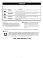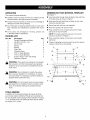
1
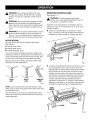
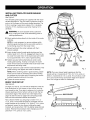
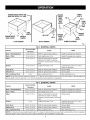
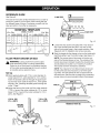
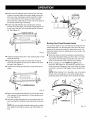
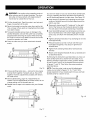
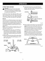
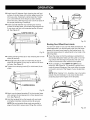
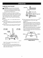
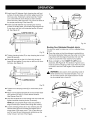
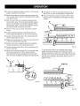
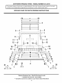
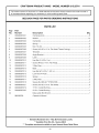
OPERATOR'S
MANUAL
II:RRFTSMRN I
ROUTER DOVETAIL JOINT
TEMPLATE KIT
MODEL NO.
315.25791
FOR USE WITH ROUTERS WITH
3-HOLE TEMPLATE GUIDE MOUNT,
_
WARNING:
To reduce the risk of injury,
the user must read and understand the
operator's manual before using this product.
Customer
Help Line: t-800-932-3188
Sears, Roebuck and Co., 3333 Beverly Rd., Hoffman
Visit the Craftsman web page: www.sears.com/craftsman
983000-533
9-04
Estates, IL 60179 USA
Save this manual for future reference
•
Introduction .....................................................................................................................................................................
2
•
General Safety Rules .......................................................................................................................................................
3
•
Symbols ...........................................................................................................................................................................
4
•
Assembly .........................................................................................................................................................................
5
•
Operation ....................................................................................................................................................................
•
Troubleshooting .............................................................................................................................................................
•
Exploded View and Parts List ...................................................................................................................................
•
Parts Ordering/Service
.....................................................................................................................................
6-18
18
19-20
Back Page
This accessory has many features for making its use more pleasant and enjoyable. Safety, performance, and
dependability have been given top priority in the design of this product making it easy to maintain and operate.
_L
•
ARNING: read and understand all instructions.
Failure to follow all instructions listed below, may
result in electric shock, fire and/or serious personal
injury.
•
SAVE THESE INSTRUCTIONS
•
Read these instructions and the instructions for
your router thoroughly before using accessory.
•
Know your power tool. Read the operator's manual
for your router carefully. Learn the router's app(ications
and limitations as well as the specific potential hazards
related to this tool.
•
Always wear safety glasses. Everyday eyeglasses
have only impact-resistant
lenses; they are not
safety glasses. Following this rule will reduce the risk
of serious personal injury.
•
•
•
•
•
•
•
_k
•
•
Always disconnect router from power supply before
making adjustments or adding accessories.
Make
sure the switch is off when reconnecting to power supply.
Keep your work area clean and well lit. Cluttered
benches and dark areas invite accidents.
•
Do not operate power tools in explosive atmospheres, such as in the presence of flammable liquids, gases, or dust. Power tools create sparks which
may ignite the dust or fumes.
Keep bystanders, children, and visitors away while
operating a power tool. Distractions can cause you to
lose control.
Stay alert, watch what you are doing and use common sense when operating a power tool. Do not
use tool while tired or under the influence of drugs,
alcohol, or medication. A moment of inattention while
operating power tools may result in serious personal
injury.
Avoid accidental starting. Be sure switch is off
before plugging in. Carrying tools with your finger on
the switch or plugging in tools that have the switch on
invites accidents.
•
Inspect tool cords periodically and, if damaged,
have repaired at your nearest authorized service
center. Constantly stay aware of cord location. Following this rule will reduce the risk of electric shock or
fire.
•
Check damaged parts. Before further use of the
tool, a guard or other part that is damaged should
be carefully checked to determine that it will operate properly and perform its intended function.
Check for alignment of moving parts, binding of
moving parts, breakage of parts, mounting, and
any other conditions that may affect its operation. A guard or other part that is damaged should
be properly repaired or replaced by an authorized
service center. Following this rule will reduce the risk
of shock, fire, or serious injury.
•
Inspect for and remove all nails from lumber before
using this tool. Following this rule will reduce the risk
of serious personal injury.
Save these instructions.
Refer to them frequently and
use them to instruct others who may use this tool. If
you loan someone this tool, loan them these instructions also.
•
Do not overreach. Keep proper footing and balance
at all times. Proper footing and balance enab(es better
control of the tool in unexpected situations.
Use clamps or other practical way to secure and
support the workpiece to a stable platform. Holding
the work by hand or against your body is unstable and
may lead to loss of control.
Disconnect the plug from power source before
making any adjustments, changing accessories,
or storing the tool. Such preventive safety measures
reduce the risk of starting the tool accidentally.
Keep the tool and its handle dry, clean and free
from oil and grease. Always use a clean cloth when
cleaning. Never use brake fluids, gasoline, petroleumbased products, or any strong solvents to clean your
tool. Following this rule will reduce the risk of loss of
control and deterioration of the enclosure plastic.
Protect your lungs. Wear a face or dust mask if the
operation is dusty. Following this rule will reduce the
risk of serious personal injury.
Protect your hearing. Wear hearing protection during extended periods of operation, Following this rule
will reduce the risk of serious personal injury.
WARNING:
Some dust created by power sanding, sawing, grinding, drilling, and other construction activities
contains chemicals known to cause cancer, birth defects or other reproductive harm. Some examples of these
chemicals are:
• lead from lead-based paints,
• crystalline silica from bricks and cement and other masonry products, and
• arsenic and chromium from chemically-treated
lumber.
Your risk from these exposures varies, depending on how often you do this type of work. To reduce your exposure
to these chemicals: work in a well ventilated area, and work with approved safety equipment, such as those dust
masks that are specially designed to filter out microscopic particles.
3
Thefollowingsignalwordsandmeanings
areintendedto explainthe levelsofriskassociated
withthisproduct.
SYMBOL
SIGNAL
MEANING
,_
DANGER:
Indicates an imminently hazardous situation, which, if not avoided, will
result in death or serious injury.
_k
WARNING:
Indicates a potentially hazardous situation, which, if not avoided, could
result in death or serious injury.
,_
CAUTION:
Indicates a potentially hazardous situation, which, if not avoided, may
result in minor or moderate injury.
CAUTION:
(Without Safety Alert Symbol) Indicates a situation
property damage.
A
SERVICE
Servicing requires extreme care and knowledge and
should be performed only by a qualified service technician. For service we suggest you return the product to
your nearest AUTHORIZED SERVICE CENTER for repair.
When servicing, use only identical replacement parts.
,_
that may result in
WARNING: To avoid serious personal injury, do
not attempt to use this product until you read
thoroughly and understand completely the
operator's manual. Save this operator's manual
and review frequently for continuing safe operation and instructing others who may use this
product.
WARNING:
The operation of any power tool can result in foreign objects being thrown into your eyes, which
can result in severe eye damage. Before beginning power tool operation, always wear safety
goggles or safety glasses with side shields and a full face shield when needed. We recommend
Wide Vision Safety Mask for use over eyeglasses or standard safety glasses with side shields.
Always use eye protection which is marked to comply with ANSI Z87.1.
SAVE THESE INSTRUCTIONS
UNPACKING
ASSEMBLING
This product requires assembly.
See Figure 1.
•
Carefully remove all parts from the box. Make sure that
all items listed in the packing list are included.
•
Insert hex bolts through holes located at top and front
of dovetail base as shown in figure 1.
•
Inspect the parts carefully to make sure no breakage or
damage occurred during shipping.
•
Make sure the bolt head flats are lined up with slots
inside the dovetail base.
•
Do not discard the packing material until you have carefully inspected and satisfactorily operated the accessory.
•
Secure hex bolt with hex nuts supplied.
•
Place one spring over each hex bolt.
•
Place a washer on top of each spring, then install
clamp bar on top of washer.
•
If any parts are damaged or missing,
1-800-932-3188 for assistance.
PACKING
LIST
Item No,
1
2
3
4
5
Description
Dovetail Template and Base
Hex Bolt (1/4-20 x 3 in.)
Nut (1/4-20)
Spring
Washer
6
7
8
9
10
11
please
call
Qty.
1
4
4
4
8
Clamp Bar
Clamping Knob
5/16 in. Guide Bushing
7/16 in. Guide Bushing
Screw (10-32 x 7/8 in. Flat Head)
Operator's Manual
•
Place a second washer on top and/or end of each
clamp bar.
•
Thread a clamping knob onto each hex bolt to secure
washers, clamp bars, and springs.
7\
2
4
1
1
3
WARNING:
If any parts are missing do not operate
this accessory until the missing parts are replaced.
Failure to do so could result in possible serious personal injury.
A
WARNING:
Do not attempt to modify this accessory. Any such alteration or modification is misuse
and could result in a hazardous condition leading to
possible serious personal injury.
_IL
WARNING:
connect Failure
routertoto comply
power supply
until assembly Do
is not
complete.
could
result in accidental starting and possible serious
injury.
TOOLS
TEMPLATE
NOTE: For proper assembly, be sure to turn each
clamp bar as shown in Figure 1.
1\
_
YOUR DOVETAIL
NEEDED
In addition to the dovetail template and guide bushing,
you will also need a Craftsman Router and a dovetail cutter. Use dovetail cutter Catalog Number 26319 for making
1/4 in. dovetail joints and Catalog Number 26318, 25505
for making 1/2 in. joints.
_7
..........
3 ..............
......................
....
9
_
8
,o
Fig. 1
_
WARNING:
Do not allow familiarity with tools
to make you careless. Remember that a careless
fraction of a second is sufficient to inflict serious
_
A
MOUNTING
DOVETAIL
BASE
See Figures 3 - 4.
injury.
_
WARNING:
Always wear safety goggles or safety
glasses with side shields when operating power
tools. Failure to do so could result in objects being
thrown into your eyes resulting in possible serious
injury.
If desired, it can be clamped to a workbench with "C"
clamps, or it can be mounted onto a 3/4 in. piece of plywood for mobility.
WARNING:
Do not use any attachments or accessories not recommended by the manufacturer of
this tool. The use of attachments or accessories not
recommended can result in serious personal injury.
•
WARNING:
For safe operation and proper
control, your router dovetail template kit must be
mounted to a workbench or table.
Clamp the dovetail base to a workbench or table
with "C" clamps. It can then be easily removed upon
completion for easy storage or changing job sites.
APPLICATIONS
You may use this tool for the purposes listed below:
See Figure 2.
•
Cutting Flush Joints
•
•
Cutting Offset Joints
Cutting Rabbeted Joints
Your router dovetail
cutting flush, offset,
curacy. Since these
are commonly used
template kit has been designed for
or rabbeted joints with speed and acjoints are both strong and neat, they
when making drawers and boxes.
C CLAMP
CLAMP
Read all instructions carefully, and follow closely while
making set ups and adjustments.
FLUSH
JOINT
OFFSET
JOINT
RABBETED
JOINT
Fig. 2
NOTE: Once all adjustments have been properly made,
make a trial cut with scrap pieces of the same wood used
for the finished work.
Fig. 3
A second, more preferred, method would be to mount
your dovetail base onto a piece of 3/4 in. plywood
approximately six inches wide and twenty-four inches
long. Position front of base flush with the front and
centered with the ends of the board, then insert four
flat head wood screws through holes in the base and
secure firmly into plywood. The dovetail base (with
wooden base) may then be clamped securely to
workbench or table with "C" clamps or other holding
apparatus. Here again, it can be easily removed upon
completion for easy storage or changing job sites.
WOOD
SCREWS
This step allows you to check your adjustments. It also
makes you aware of the characteristics of the particular
wood being used.
PLYWOOD
C CLAMP
Fig. 4
INSTALLING TEMPLATE
AND CUTTER
GUIDE
BUSHING
See Figure 5.
Two template guide bushings are supplied with the router
dovetail template kit. They are used to guide the router in
and out of the fingers of the comb-shaped template. The
5/16 in. bushing is used when making 1/4 in. dovetails,
while the 7/16 in. bushing is used when making 1/2 in.
dovetails.
_
CLAMP
WARNING:
To avoid possible serious personal
injury, unplug the router while assembling parts or
making adjustments.
• Attach guide bushing directly to the inside of the router
subbase.
NOTE: It is not necessary to remove subbase while
attaching guide bushing, but be sure collar section is
turned facing away from the router motor.
•
Secure bushing to the router subbase with the 3
screws supplied.
•
Insert dovetail cutter through guide bushing and into
collet at least 3/4 in. If 3/4 in. engagement does not exist, lower the router motor in the router base until collet
nut is approximately 1/8 in. clear of guide bushing.
• Tighten securely before attempting to center cutter
inside guide bushing. If clamp is not tight, the router
motor will be loose and wobble inside router base while
adjustments are being made.
SUBBASE
SCREW
_
DOVETAIL
CUTTER
SCREWS
GUIDE
BUSHING
• Visually center the cutter with the inside diameter of the
guide bushing, then tighten the collet nut securely.
NOTE: When centering cutter in guide bushing, adjustments can be made by loosening the screws holding
the subbase to the router and/or loosening the screws
holding the guide bushing to the router.
• Tighten all screws securely.
Fig. 5
NOTE: Plan your drawer height opening so that the
boards will be in increments of 7/8 in. for 1/2 in. joints, or
29/64 in. increments for 1/4 in. joints. This will allow a halfpin to be on both the top and bottom edge of the drawer
front. Don't forget to allow for clearances.
BEGIN YOUR SET-UP
See Figure 6.
To begin your set-up, you will need to determine what the
final dimensions for your drawer or box will be, then cut
your boards to size. If you plan in advance, try to size the
drawer opening so that a half-pin will be on both the top
and bottom edge of the drawer front. See helpful hints,
page 18. See the chart on page 8 for computing proper
sizes and recommended material thicknesses.
Next, decide whether you are going to make 1/4 in. or
1/2 in. joints. The dovetail template is packaged with the
angle brackets set for making 1/2 in. joints. If 1/4 in. joints
are desired, loosen the two screws holding the angle
brackets, and reverse them 180 °. Re-tighten angle bracket
screws. Reverse the procedure when changing your template from 1/4 in. joints to 1/2 in. joints.
ANGLEBRACKET
Fig. 6
DRAWERHEIGHTFRONTAND
BACKSIDE WIDTH 12 in. MAX.
DRAWER
HEIGHT
BACK
WIDTH
SIDE
WIDTH
FRONT
LENGTH
3/8 in.
3R in.
FRONT
WIDTH
MAX.
3_ in.
SIDE
LENGTH
DRAWERWIDTH
BACKLENGTH
DRAWER
LENGTH
HALF-PIN
1/16 in.
FLUSH DRAWER
DRAWER
LENGTH
DRAWER
WIDTH
BACK
LENGTH
OFFSETDRAWER
SIDE
LENGTH
RABBETEDDRAWER
Fig, 7
1/2 in. DOVETAIL
JOINTS
Recommended
Section
Length
Thickness
Width
Back - Flush/Rabbeted
1/2 in. to 3/4 in.
Width of opening less clearance
Height of opening less clearance
Back - Offset
1/2 in. to 3/4 in.
Front length minus 1/8 in.
Height of opening less clearance
Sides
1/2 in. to 3/4 in.
Must be determined for each job
depending on depth of opening,
clearance, and thickness of front and
back
Same as back
Bottom
1/4 in. to 3/8 in.
Length of side less 1/4 in.
Length of back, plus 1/2 in. less 2
times side thickness
Flush Front
1/2 in. to 3/4 in.
Width of opening less clearance
Same as Back
Offset-Front
1/2 in. to 3/4 in.
Width of opening less clearance
Same as Back
Back Length plus 3/4 in.
Back width plus 3/4 in.
3/8 in. Rabbeted Front
3/4 in.
NOTE: Front, back and sides should be grooved 1/4 in. deep to receive bottom piece and may be done before or after dovetailing.
groove depth is more or less than 1/4 in., bottom dimensions must be altered to compensate.
1/4 in, DOVETAIL
JOINTS
Recommended
Section
Length
Thickness
Width
Back - Rush/Rabbeted
5/16 in. to 3/4 in.
Width of opening less clearance
Height of opening less clearance
Back - Offset
5/16 in. to 3/4 in.
Front length minus 1/8 in.
Height of opening less clearance
Must be determined for each job
depending on depth of opening,
clearance, and thickness of front and
back
Same as back
Length of side less 1/4 in.
Length of back, plus 1/2 in. less 2
times side thickness
Sides
1/4 in. to 1/2 in.
Bottom
1/4 in.
Flush Front
5/16 in. to 3/4 in.
Width of opening less clearance
Same as Back
Offset-Front
5/16 in. to 3/4 in.
Width of opening less clearance
Same as Back
Back Length plus 3/4 in.
Back width plus 3/4 in.
3/8 in. Rabbeted
Front
1/2 in. to 3/4 in.
NOTE: Front, back and sides should be grooved 3/16 in. deep to receive bottom piece and may be done before or after dovetailing.
If groove depth is more or less than 3/16 in., bottom dimensions must be altered to compensate.
8
If
REFERENCE
GUIDE
See Figure 8.
The base of the router dovetail template kit has a label to
serve as a guide for you to follow when making set-ups
for different types of joinery. Familiarize yourself with this
label and refer to it as often as necessary.
DOVETAIL
1/2 in. Tails
JOINT
_
BRACKET
LOCATION
BIT
DEPTH
FLUSH
A
A
1
17/32 in.
OFFSET
A
A
2
_ABBETED
R
A
3
I
JOINT
STOP
1/4 in. Tails
_STOP
I TOP ISlUEI
BRACKET
LOCATION
I
BfT
DEPTH
FLUSH
C
C
1
7/16 in.
17/32 in.
OFFSET
C
C
2
7/16
in.
17/32in.
RABBETED
R
C
3
7/16
in.
1
Fig. 10
2
3
Loosen the stop screws and place the 3 way stop on
top of the dovetail base and the 2 way stop on the
side of the dovetail base in their proper position. See
Figures 8 and 10. Retighten stop screws securely.
Mark the boards for the drawer or box on the inside with
identifying letters near the bottom edge. See Figure 11.
Fig. 8
FLUSH FRONT
_
DRAWER
NOTE: The reverse side of the board will be the outside of the finished drawer or box. The outside of the
boards are always clamped towards the dovetail base
and all pieces are routed in an "inside-out" position.
The boards are then reversed to assemble.
OR BOX
WARNING:
Unplug router from power supply
while assembling parts or making adjustments.
Failure to do so could result in accidental starting
of the router causing damage to the work surface
or possible serious personal injury.
NOTE: The material for front (B) and back (D) should
be the same size and should be cut to fit the opening neatly. The side pieces (A and C) should also be
the same size. See the chart on page 8 for computing
proper sizes and recommended material thicknesses.
Set Up
• Attach guide bushing with 7/16 in. pilot diameter to
router base (5/16 in. pilot diameter for 1/4 in. joints).
Insert the dovetail cutter bit through the guide bushing and into chuck collet at least 3/4 in., then tighten
securely. See "Installing template guide bushing and
cutter", Page 7.
• Adjust
17/32
Adjust
joints.
_
TEMPLATE
MODEL 315.25791
STOP
3 WAY STOP
SIDE (A)'_
the base on the router until the cutter extends
in. beyond the router subbase for 1/2 in. joints.
7/16 in. beyond the router subbase for 1/4 in.
See Figure 9.
_"
m---I
///_BOTTOM
_"
BACK(D)_
GROOVE
FLUSHFRONT(B)
¢...j"
17/32 in. FOR
1/2 in. JOINTS
SIDE(C)
, _j
7/16 in. FOR
1/4 in. JOINTS
RABBETEDFRONT(B)
DOVETAIL
CUTTER
Fig. 11
SUBBASE
Fig. 9
9
• Insertboard(A)betweenfrontclampingbarandfront
surfaceof dovetailbasewithbottomedgetowardthe
left2-waystop.Temporarily
clampboard(A)"insideout"to theleftfrontofthefixtureso thatit extends
abovethebase.See Figure 12. This is done to assist in
the proper positioning of board (B).
• Insert board (B) between top clamping bar and top
surface of dovetail base, with bottom edge against left
3-way stop, and flush with extended portion of board
(A). See Figure 12.
CLAMPINGKNOB(E)
H
G
G
Fig. 14
Routing
Your Flush Dovetail
Joints
You are now ready to rout your first flush dovetail joint. As
mentioned earlier, you should make a trial cut with scrap
pieces of the same wood used for the finished work. Using scrap pieces allows for adjustments to be made in the
following steps.
Fig. 12
•
Place the router so that the subbase is resting flat on
the dovetail template. Make sure the cutter is not making contact with the edge of board (A), then turn your
router on and let the motor build to its full speed.
•
Make a straight cut from RIGHT TO LEFT across
board (A). See Figure 15. This shallow V-groove cut is
made to prevent chipping of the wood when the router
is moved in and out of the fingers of your dovetail template.
• Tighten clamping knobs (E) on top clamping bar to hold
board (B) securely.
• Relocate board (A) so that it is flush with the top of
board (B) and against 2-way stop on left front of dovetail base. See Figure 13.
• Tighten front clamping knobs (E) to hold board (A) securely.
NOTE: When making 1/4 in. dovetails, one or two extra
passes may be necessary to cut away excess stock
projecting beyond the fingers of the dovetail template.
CLAMPINGKNOB(E)
Fig. 13
• Attach comb-shaped template (F) to the dovetail base
with washers (G) and spacers (H) in their desired location. See Figure 14.
• Hold the dovetail template flat on the boards with one
hand, and tighten template clamping knobs (E) securely.
GROOVECUT
NOTE: Be sure dovetail template finger ends are parallel to edge of board (B) to assure even fitting after cutting.
Fig. 15
10
,_
Youarenowreadyto routyoursecondflushdovetailjoint.
Doso by repeating
theaboveprocedure
withboards(C)
and(B)positionedagainsttherightstops.See Figure 16.
WARNING:Usecaution
whenoperating
routerat
eitherextremeendof dovetail
template.Thedovetail cutterwill makecontactwithanglebracketif
movedtoofaroutsidefirstor finalcut.
• Cutthedovetailjoint.Feedthe routerinandouteach
finger,movingfromleftto right.
• Recutthedovetailmovingtherouterfromrightto left.
Thiswillcleanoffanyspotsor imperfections
thatmight
havebeenmissed.
• Topreventpossibleseriousinjuryor damagetothe
dovetailtemplate,waituntilthe cutterhascompletely
stoppedbeforeremovingtherouter.Whenremoving
the routerit shouldnotbeliftedbutshouldbemoved
towardtheoperatoruntilclear.
• Checkto makesureyouhaveroutedeachdovetail
evenly.
•
Insert board (C) between front clamping bar and front
surface of dovetail base with bottom edge toward the
right 2-way stop.
•
Temporarily clamp board (C) "inside-out" to the right
front of the fixture so that it extends above the base.
This will assist in the proper positioning of board (B).
•
Insert board (B) between top clamping bar and top surface of dovetail base, with bottom edge against right
3-way stop, and flush with extended portion of board
(C).
•
Tighten clamping knobs (E) on top clamping bar to hold
board (B) securely.
•
Relocate board (C) so that it is flush with the top of
board (B) and against 2-way stop on right front of
dovetail base.
•
Tighten front clamping knobs (E) to hold board (C)
securely.
•
Attach comb-shaped
as described above.
template (F) and cut dovetail joint
By following the instructions just described, you have cut
flush dovetail joints for a drawer front and sides. If you
desire to dovetail cut the back corners, position boards
(A and D) and (C and D) in the dovetail fixture as shown
in figures 17 and 18. Then follow the same procedure
described above.
Fig.16
NOTE: Once the router is set-up and all adjustments
made, you can refer to figures 12, 16, 17 and 18 for
proper placement of your boards each time you cut flush
dovetail joints for a drawer or box.
• Onceeverything
looksokay-- removethetwopieces
andtapthemtogether.If properlysetup,theywillfit
together.However,
adjustments
probablywillneedto
bemadeatfirst.
• Seetroubleshooting,
page18,if adjustments
are
needed.Oncealladjustments
havebeenmade,donot
changesettinguntilalldovetailsarecut.
• Repeatfirstsixstepsinthissectionwithyourfinished
wood.
Fig. 18
Fig. 17
11
OFFSET-FRONT
,_
• Loosen the stop screws on your dovetail base and
place the 3 way stop on top and the 2 way stop on
the side in their proper position. See Figures 8 and 20.
Retighten stop screws securely.
DRAWER
WARNING:
Unplug router from power supply
while assembling parts or making adjustments.
Failure to do so could result in accidental starting
of the router causing damage to the work surface
or possible serious personal injury.
3 WAY STOP
An Offset-Front drawer, often called flush-Offset, is used
when the drawer front is the same height as the drawer
sides, but the drawer front is 1/8 in. longer than the width
of the drawer. Therefore, the drawer sides are recessed
1/16 in. into each side of the drawer front. See Figure 2.
STOP
Set-Up
The Set-Up for an Offset-Front drawer is done exactly the
same as a set-up for a flush front drawer or box, page 9,
with one exception. The exception being where the angle
brackets of the comb-shaped template are located on the
dovetail base. See Figure 8. The angle brackets of the
comb-shaped template go between spacers (G) and (H).
See Figure 24.
Fig. 20
Mark the boards for the drawer or box on the inside with
identifying letters near the bottom edge. See Figure 21.
NOTE: The reverse side of the board will be the outside of the finished drawer or box. The outside of the
boards are always clamped towards the dovetail base
and all pieces are routed in an "inside-out" position.
The boards are then reversed to assemble.
NOTE: This set-up is used for the drawer front only. The
drawer back is cut the same as a flush front drawer as
described on pages 9 and 10.
• Attach guide bushing with 7/16 in. pilot diameter to
router base (5/16 in. pilot diameter for 1/4 in. joints).
Insert the dovetail cutter bit through the guide bushing and into chuck collet at least 3/4 in., then tighten
securely. See "Installing template guide bushing and
cutter", Page 7.
• Adjust
17/32
Adjust
joints.
NOTE: The material for front (B) and back (D) should
be the same size and should be cut to fit the opening neatly. The side pieces (A and C) should also be
the same size. See the chart on page 8 for computing
proper sizes and recommended material thicknesses.
the base on the router until the cutter extends
in. beyond the router subbase for 1/2 in. joints.
7/16 in. beyond the router subbase for 1/4 in.
See Figure 19.
17/32 in. FOR
1/2 in. JOINTS
SIDE (A) "_/'_
7/16 in. FOR
1/4 in. JOINTS
_"
_m---I
SIDE (C)
///_BOTTOM
_
BACK(D)_
_f
GROOVE
FLUSHFRONT(B)
DOVETAIL
CUTTER
I
SUBBASE
Fig. 21
Fig. 19
12
• Insertboard(A)betweenfrontclampingbarandfront
surfaceof dovetailbasewithbottomedgetowardthe
left2-waystop.Temporarily
clampboard(A)"insideout"to theleftfrontofthefixtureso thatit extends
abovethebase.See Figure 22. This is done to assist in
the proper positioning of board (B).
• Insert board (B) between top clamping bar and top
surface of dovetail base, with bottom edge against left
3-way stop, and flush with extended portion of board
(A). See Figure 22.
CLAMPINGKNOB(E)
H
Fig. 24
Routing
Your Offset-Front
Joints
You are now ready to rout your first offset dovetail joint. As
mentioned earlier, you should make a trial cut with scrap
pieces of the same wood used for the finished work. Using scrap pieces allows for adjustments to be made in the
following steps.
Fig. 22
• Tighten clamping knobs (E) on top clamping bar to hold
board (B) securely.
• Relocate board (A) so that it is flush with the top of
board (B) and against 2-way stop on left front of dovetail base. See Figure 23.
• Tighten front clamping knobs (E) to hold board (A) securely.
•
Place the router so that the subbase is resting flat on
the dovetail template. Make sure the cutter is not making contact with the edge of board (A), then turn your
router on and let the motor build to its full speed.
•
Make a straight cut from RIGHT TO LEFT across
board (A). See Figure 25. This shallow V-groove cut is
made to prevent chipping of the wood when the router
is moved in and out of the fingers of your dovetail template.
NOTE: When making 1/4 in. dovetails, one or two extra
passes may be necessary to cut away excess stock
projecting beyond the fingers of the template.
CLAMPINGKNOB(E)
Fig. 23
• Attach comb-shaped template (F) to the dovetail base
with washers (G) and spacers (H) in their desired location. See Figure 24.
• Hold the template flat on the boards with one hand,
and tighten template clamping knobs (E) securely.
NOTE: Be sure template finger ends are parallel to
edge of board (B) to assure even fitting after cutting.
GROOVECUT
Fig. 25
13
_
Youarenowreadyto routyoursecondoffsetdovetail
joint.Doso byrepeating
the aboveprocedure
withboards
(C)and(B)positionedagainsttherightstops.
ARNING:Usecaution
whenoperating
routerat
eitherextreme
endofdovetail
template.Thedovetailcutterwillmakecontactwithanglebracketif
movedtoo faroutsidefirstorfinalcut.
See Figure 26.
• Cutthedovetailjoint.Feedthe routerinandouteach
finger,movingfromleftto right.
• Recutthedovetailmovingthe routerfromrightto left.
Thiswillcleanoff anyspotsor imperfections
thatmight
havebeenmissed.
• Topreventpossibleseriousinjuryor damageto the
dovetailtemplate,waituntilthecutterhascompletely
stoppedbeforeremoving
the router.Whenremoving
the routeritshouldnotbeliftedbut shouldbemoved
towardtheoperatoruntilclear.
• Checkto makesureyouhaveroutedeachdovetail
evenly.
•
Insert board (C) between front clamping bar and front
surface of dovetail base with bottom edge toward the
right 2-way stop.
•
Temporarily clamp board (C) "inside-out" to the right
front of the fixture so that it extends above the base.
This will assist in the proper positioning of board (B).
•
Insert board (B) between top clamping bar and top surface of dovetail base, with bottom edge against right
3-way stop, and flush with extended portion of board
(C).
•
Tighten clamping knobs (E) on top clamping bar to hold
board (B) securely.
•
Relocate board (C) so that it is flush with the top of
board (B) and against 2-way stop on right front of
dovetail base.
•
Tighten front clamping knobs (E) to hold board (C)
securely.
•
Attach comb-shaped
as described above.
template (F) and cut dovetail joint
By following the instructions just described, you have cut
offset dovetail joints for a drawer front and sides. If you
desire to dovetail cut the back corners, position boards
(A and D) and (C and D) in the dovetail fixture as shown in
figures 27 and 28, but use the comb position shown in figure 14. Then follow the same procedure described above.
Fig.26
NOTE: Once the router is set-up and all adjustments
made, you can refer to figures 23, 26, 27 and 28 for
proper placement of your boards each time you cut offset
dovetail joints for a drawer or box.
• Onceeverything
looksokay-- removethetwo pieces
andtapthemtogether.If properlysetup,theywillfit
together.However,
adjustments
probablywill needto
bemadeatfirst.
• Seetroubleshooting,
page18,ifadjustments
are
needed.Oncealladjustments
havebeenmade,do not
changesettinguntilalldovetailsarecut.
• Repeatfirstsixstepsinthissectionwithyourfinished
wood.
Fig. 28
Fig. 27
14
RABBETED
FRONT
DRAWER
3 WAY STOP
,_
WARNING:
Unplug router from power supply
while assembling parts or making adjustments.
Failure to do so could result in accidental starting
of the router causing damage to the work surface
or possible serious personal injury.
A rabbeted front drawer is used when you want the
drawer front to overlap the top, bottom, and both sides of
the drawer opening. The drawer front is both 3/4 in. wider
than the drawer sides and 3/4 in. longer than the drawer
width. This will give you a 3/8 in. rabbet around your
drawer front after you finish cutting your dovetail joints.
STOP
Fig. 30
Set-up
•
Mark the boards for the drawer or box on the inside
Cut a 3/8 in. wide x 7/16 in. deep rabbet around the
drawer front.
with identifying letters near the bottom edge.
See Figure 31.
NOTE: The reverse sides of the board will be the outside of the finished drawer or box. The outside of the
• Attach guide bushing to your router and install dovetail
cutter. See "Installing template guide bushing and cutter", Page 7.
boards are always clamped towards the dovetail base
and all pieces are routed in an "inside-out" position.
The boards are then reversed to assemble.
• Adjust the base on your router until the cutter extends
17/32 in. below the router subbase for 1/2 in. joints.
17/32 in. FOR
1/2 in. JOINTS
NOTE: The front piece (B) should be 3/4 in. longer and
3/4 in. wider than the back piece (D). The side pieces
(A and C) should be the same size. See the chart on
page 9 for computing proper sizes and recommended
material thicknesses.
7/16 in. FOR
1/4 in. JOINTS
DOVETAIL
CUTTER
SUBBASE
SIDE (C)
if
RABBETEDFRONT(B)
Fig. 29
Fig. 31
Adjust 7/16 in. below the router subbase for 1/4 in.
joints. See Figure 29.
•
Loosen the stop screws in your dovetail base and
place the 3-way stop on top and the 2-way stop on the
side in their proper position. See Figures 8 and 30. Retighten stop screws securely.
15
• Insertboard(A)betweenfrontclampingbarandfront
surfaceof dovetailbasewithbottomedgetowardthe
left2-waystop.Temporarily
clampboard(A)"insideout"to theleftfrontofthefixtureso thatit extends
abovethebase.See Figure 32. This is done to assist in
the proper positioning of the board (B).
•
Insert board (B) between top clamping bar and top
surface of dovetail base, with bottom edge against left
3-way stop, and flush with extended portion of board
(A). See Figure 32.
G
CLAMPINGKNOB(E)
G
H
Fig. 34
Routing
Your Rabbeted
Dovetail
Joints
You are now ready to make your cut for a rabbeted dovetail joint.
Fig. 32
•
Place the router so that the subbase is resting flat on
the dovetail template. Make sure the cutter is not making contact with the edge of board (A), then turn the
router on and let the motor build to its full speed.
•
Make a straight cut from RIGHT TO LEFT across
board (A). See Figure 35. This shallow V-groove cut is
made to prevent chipping of the wood when the router
is moved in and out of the fingers of the dovetail template.
_
ARNING: Use caution when operating router at
either extreme end of dovetail template. Your cutter will make contact with angle bracket if moved
too far outside first or final cut.
• Tighten clamping knobs (E) on top clamping bar to hold
board (B) securely.
•
Relocate board (A) so that it is flush with the top of
board (B) and against 2-way stop on left front of dovetail base. See Figure 33.
CLAMPINGKNOB(E)
Fig. 33
• Tighten front clamping knobs (E) to hold board (A) securely.
• Attach comb-shaped template (F) to the dovetail base
with spacers (G) and (H) in their desired location.
See Figures 8 and 34.
•
Hold the template flat on the boards with one hand and
tighten template clamping knobs (E) securely.
NOTE: Be sure template finger ends are parallel to
edge of board (B) to assure even fitting after cutting.
•
GROOVECUT
Loosen clamping knobs (E) on top clamping bar and
remove board (B) from the base and replace with a
scrap piece of the same wood. This will provide support for board (A) and help prevent splintering as the
cutter moves in and out of the fingers.
Fig. 35
16
• Cutyourdovetailjoint.Feedtherouterinandouteach
finger,movingfromleftto right.
• Recutthedovetailmovingtherouterfromrightto left.
Thiswillcleanoffanyspotsor imperfections
thatmight
havebeenmissed.
• Waituntilthecutterhascompletelystoppedbefore
removingtherouter.Thiswillpreventpossibleserious
injuryoranydamagetothe dovetailtemplate.When
removingtherouter,it shouldnotbeliftedbutshould
bemovedtowardtheoperatoruntilclear.
• Checkto makesureyouhaveroutedeachdovetail
evenly.
• Loosentemplateclampingknobs(E)andremove
comb-shaped
template(F).donot removeboard(A).
• Loosenclampingknobs(E)ontop clampingbarand
removescrappieceof wood.
• Replacethescrappieceofwoodwiththepiecethatis
to beyourfinishedfrontboard(B).
• Placeitflushwiththeedgeof board(A),andtighten
clampingknobs(E)ontop clampingbarfirmly.
• Loosenclampingknobs(E)onfrontclampingbarand
removeboard(A).
• Attachcomb-shaped
template(F)to thedovetailbase
withspacers(G)and(H)intheirdesiredlocation.
•
See Figure 37. With the dovetail template set-up as
shown, cut your joint in board (B) as a single piece.
•
Recut the dovetail moving from right to left to clean
off any spots or imperfections that might have been
missed.
Fig. 37
To rout the other side of your rabbeted front drawer,
repeat the above procedure with boards (C) and (B)
positioned against the right stops. See Figure 38. To rout
dovetail cuts in board (D) and boards (A and C) follow the
instructions for making a "flush front drawer or box" on
pages 10 and 11.
See Figure 36. Hold the template flat on the boards
with one hand and tighten clamping knobs (E) securely.
BOARD(B)
H
G
Fig. 36
Fig. 38
17
HELPFUL
HINTS
•
Don't let familiarity make you careless.
•
Always bevel the drawer front for an offset-front
drawer.
• Always clamp workpiece securely for cutting.
•
Study all safety rules and do the job safely.
•
•
Plan your drawer height opening so that the boards will
be in increments of 7/8 in. for 1/2 in. joints, or 29/64 in.
increments for 1/4 in. joints. This will allow a half-pin
to be on both the top and bottom edge of the drawer
front. Don't forget to allow for clearances.
•
NEVER place your hands in jeopardy.
•
Make certain clamps can't loosen while in use.
•
Test difficult set-ups on scrap -- Don't waste lumber.
•
•
Plan each operation before you begin.
THINK SAFETY BY THINKING AHEAD,
•
Once all adjustments are made, do not make any further changes until all dovetails are cut.
Rout dovetails from the front only.
• A safe operator is one who thinks ahead.
•
Do not raise or lower your router or cutter while the bit
is between the dovetail template fingers.
•
Keep router base flat against template.
• Always wear eye protection when routing.
•
Make certain the ends of all boards are square.
•
Make set-up adjustments carefully. Then double check.
Measure twice and cut once.
•
DO NOT use warped boards.
•
Keep cutters clean and properly sharpened.
•
Be consistent when selecting the thickness of your
boards.
PROBLEM
SOLUTION
If the joint is too tight
Raise the cutter very slightly. This will make the cut more
shallow (approximately 1/64 in.). See depth adjustment
instructions as explained in the router operator's manual.
If the joint is too loose
Lower the cutter bit very slightly to make the cut deeper
(approximately 1/64 in.).
If the fit is too deep
_
Turn the lock nut (I) in a counter-clockwise direction until
desired depth is reached. See Figures 14, 17, or 18.
NOTE: Be sure to adjust both lock nuts equally.
]
]
__Fig.
39
If the fit is too shallow
Turn the lock nut (I) in a clockwise direction until the desired depth is reached. NOTE: Be sure to adjust both lock
nuts equally.
Fig. 40
18
CRAFTSMAN
PRODUCT
NAME
- MODEL
NUMBER
315.25791
[
The model number will be found on a plate attached to the motor housing. Always mention the model
number in all correspondence
regarding your accessory or when ordering repair parts.
SEE BACK
PAGE FOR PARTS ORDERING
I"
_
2
INSTRUCTIONS
I"
,_3
I
9
/
f
t
16
2
17
I
19
3
* Standard Hardware Item - May Be Purchased Locally
** Available From Div. 98 - Source 980.0
*** Complete assortment
available at your Nearest Sears Retail Store
19
6
2
1
]
CRAFTSMAN
I
PRODUCT
NAME - MODEL
NUMBER
315.25791
]
The model number will be found on a label attached to the base. Always mention the model number in
all correspondence regarding your accessory or when ordering repair parts.
SEE BACK PAGE FOR PARTS ORDERING
INSTRUCTIONS
PARTS LIST
Key
No.
Part
Number
Description
1
000900067001
Clamping Knob ...............................................................................................
2
000900067002
Washer ..........................................................................................................
3
000900067003
Clamp Bar .......................................................................................................
2
4
000900067004
Spring ..............................................................................................................
4
5
000900067005
Nut (1/4-20) .....................................................................................................
6
6
000900067006
7
000900067007
Template ..........................................................................................................
1
8
000900067008
Angle Bracket ..................................................................................................
2
9
000900067009
Label ................................................................................................................
1
10
000900067010
Hex Bolt (1/4-20 x 3 in.) ..................................................................................
4
11
000900067011
* Screw (#8-32 x 7/8 in. Flat Head) ....................................................................
4
12
000900067012
3 Way Stop ......................................................................................................
2
13
000900067013
Base ................................................................................................................
1
14
000900067014
Hex Bolt (#1/4-20 x 1-3/4 in.) ..........................................................................
2
15
000900067015
Lock Nut (#1/4-20) ..........................................................................................
2
16
000900067016
Spacer .............................................................................................................
2
17
000900067017
2 Way Stop ......................................................................................................
2
18
000900067018
Square Nut (#8-32) **STD541008
...................................................................
4
19
000900067021
* Screw (#10-32 x 7/8 in. Flat Head) ..................................................................
3
20
000900067019
7/16 in. Guide Bushing ....................................................................................
1
21
000900067020
5/16 in. Guide Bushing ....................................................................................
1
Data Label (Not Shown) ..................................................................................
1
Qty.
* Screw (#10-32 x 1/2 in. Flat Head Thread Cutting) .........................................
22
983000533
Operator's
Manual
* Standard Hardware
Item - May Be Purchased
Locally
** Available From Div. 98 - Source 980.0
*** Complete
assortment
available at your Nearest Sears Retail Store
2O
6
12
2