1
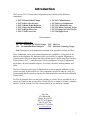
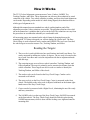
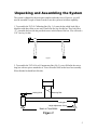
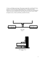
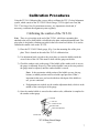
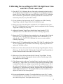
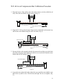
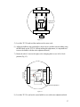
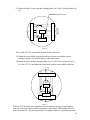
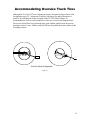
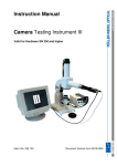
Operation and Service Manual
Laser Wheel Alignment System
TLT-12
Truck, Trailer, and RV
Alignment System
8231 Blaine Rd.
Blaine, WA 98230
360-371-0552 Phone
360-371-0553 Facsimile
800-496-3777 Toll Free
www.Tru-Line.net
1
Table of Contents
Introduction......................................................................................................................... 3
How it Works...................................................................................................................... 4
Reading the Targets: ....................................................................................................... 4
Unpacking and Assembling the System ............................................................................. 5
Calibration Procedures........................................................................................................ 7
Calibrating the camber of the TLT-30. ........................................................................... 7
Calibrating the TLT-56 Digital Level…………………………………………………..8
Calibrating the toe settings for TLT-36 right Laser Gun and TLT-37 left Laser Gun. .. 9
Calibration of the TLT-44................................................................................................. 10
General Alignment Procedure........................................................................................... 13
Mounting the TLT–28 Wheel Clamps.............................................................................. 15
Run-Out Procedure ........................................................................................................... 16
Run Out Procedure:....................................................................................................... 16
Accommodating Oversize Truck Tires............................................................................. 19
Measuring Camber:....................................................................................................... 20
Measuring Caster: ......................................................................................................... 20
Measuring Caster with the TLT-56 Digital Level.........................................................22
Measuring SAI/KPI: ..................................................................................................... 21
Measuring Caster, Camber and SAI/KPI on a Non-Level Surface .................................. 23
To Measure Camber on a Non-Level Surface .............................................................. 23
To Measure the Side to Side Tilt for SAI/KPI.............................................................. 23
To Measure Front to Rear Tilt for Caster ..................................................................... 24
Live Caster Adjustment .................................................................................................... 25
Two-Wheel Centerline Alignment.................................................................................... 26
Reading Toe Procedure:................................................................................................ 26
Two-Wheel Centerline Alignment Procedure: ............................................................. 26
Tracking & Offset ............................................................................................................. 29
Tracking Procedure:...................................................................................................... 29
Offset Procedure: .......................................................................................................... 30
MAINTENANCE, WARRANTY & SERVICE .............................................................. 32
Maintenance:................................................................................................................. 32
Two Year Limited Warranty:........................................................................................ 32
SERVICE INSTRUCTIONS ........................................................................................ 33
2
Introduction
The Tru-Line TLT-12 Laser Wheel Alignment System consists of the following
components:
2- TLT-28 Truck Wheel Clamps
1- TLT-30 Easy Check Gauge
1- TLT-31 Brake Pedal Depressor
1- TLT-32 Steering Wheel Holder
1- TLT-36 Right Laser Gun
1- TLT-37 Left Laser Gun
1- TLT-41 Calibration Bar
1- TLT-44 Level Compensator
1- TLT-51 Calibration Laser
1- TLT-52 Wheel Centering Target
1- TLT-53 King Pin Center Target
1- TLT-56 Digital Level
Documentation
Optional components:
TL – 28 Passenger Car Wheel Clamps
TLT – 29 Aluminum Wheel Adapters
TLT – 502 Case
TLT – 60 Frame Centering Targets
Note: Drawings of each component is included in the procedure sections to follow.
These components can be used with an alignment rack, turntables, or slip plates in the
front to do an alignment. No dedicated rack or level surface is required. Alignment of
vehicles can be easily done almost anywhere and the type of vehicle range from Tractors,
Trailers, Busses, R.V. `s, and other types of heavy equipment. All types of alignments
can be done, the most common being toe, two-wheel centerline, tracking/tandem, and
offset.
The Laser Guns are stored on the Calibration Bar, so that a complete calibration of the
system can easily be done before use. The components can also be hung on a wall. It is
recommended that the system be checked for calibration before each use and recalibrated
when needed.
Tru-Line is pleased to have you and your company as a client. We are available to you to
answer any questions that you may have. Please feel free to contact us if there is anything
further we can do to make Tru-Line a better product for you and your company.
Tru-Line
8231 Blaine Rd.
Blaine, WA 98230
360-371-0552 phone
360-371-0553 fax
800-496-3777 toll free
www.tru-line.net
3
How it Works
The TLT-12 wheel alignment system measures Caster, Camber, SAI/KPI, Toe,
Tracking/Tandem, and Offset. These alignments can reference the mechanical or actual
centerline of the vehicle. Two-wheel centerline, tracking, and four-wheel total alignments
can be made. Depending on the model of vehicle being aligned, the technician chooses
which type of alignment to do.
Although this manual presents standard two-wheel, tracking/tandem, and offset
alignment procedures, other variations are possible. The procedures that have been laid
out in the manual are a guideline that is proven in the field. The technician can vary from
the procedures to accommodate what they are comfortable with.
All measuring gauges are mounted on the wheel clamps by hanging them on the
mounting disk. If a clamp is dropped you will not damage the system itself. The Easy
Check Gauge is used to measure caster, camber and SAI/KPI. The two Laser Guns and
the wheel targets are used to measure Toe, Tracking/Tandem, and Offset.
Reading the Targets:
1. The toe scale is used to dial desired toe specifications into both Laser Boxes. Toe
can be measured in millimeters, inches, or degrees. The toe scale is located on the
top of each Laser Box and is used in conjunction with the toe adjustment knobs
and dial rings.
2. The centering targets are used in two-wheel centerline, Tracking/Tandem, and
Offset alignment. The target is primarily used to measure the distance from the
vehicle centerline. These targets can also be used on a trailer to identify the
Tracking/Tandem, and Offset of the wheels.
3. The camber scale can be found on the Easy Check Gauge. Camber can be
measured on all wheels
4. The caster scale is on the Easy Check Gauge. Caster is measured on the front
wheels. The bubble on the caster scale is adjusted with knob on the bottom righthand corner of the Easy Check Gauge.
5. Caster can also be measured with a Digital Level, eliminating the need for costly
and heavy turn tables.
6. The SAI/KPI scale is on the top of the Easy Check Gauge. SAI/KPI is measured
on the front wheels. The Easy Check Gauge should be locked in place during
SAI/KPI measurement, which is done with the locking screw tightened onto the
mounting disk.
4
Unpacking and Assembling the System
The system is shipped for the most part complete and ready to use. However, you will
need to assemble a couple of items in order to use the system to its fullest capability.
1. To assemble the TLT-41 Calibration Bar (Fig. 1). Locate the bar which looks like a
black bar with three disks on one end. Then locate the legs for this bar. They look like a
“T”. Assemble the bar with the provided screws in the bottom of the bar. You will need a
5/32” hex key for this.
Figure 1
2. To assemble the TLT-44 Level Compensator Bar, (Fig. 2) you will find in the crate a
long bar with two pieces attached to it. You will need to slide on the base foot assembly.
When finished it should look like this.
Locking Knob
Mounting Disk
Locking Nut
Height Adjustment Screw
Match to Tread Width
Figure 2
5
3. Next you will find a pair of targets. These targets mount either on the King Pin Target
kit, (Fig. 3) or the Wheel Chock Target Stands (Fig. 4). The targets have plastic
thumbscrews for easy mounting and dismounting. Please note that when assembling these
Targets, they must be mounted exactly mirror image from each other in order to obtain
the highest accuracy. When assembled they should look like this:
12 11 10 9 8 7 6 5 4 3 2 1
1 2 3 4 5 6 7 8 9 10 11 12
Target Kits
Figure 3
12 11 10 9 8 7 6 5 4 3 2 1
Wheel Chock Target
Figure 4
6
Calibration Procedures
Using the TLT-41 Calibration Bar, you are able to calibrate the TLT-12 wheel alignment
system, which consist of the TLT-30 EZ Check Gauge, TLT-36 right Laser Gun, and
TLT-37 left Laser Gun. For maximum accuracy, it is important to check and, if
necessary, recalibrate the alignment system regularly.
Calibrating the camber of the TLT-30.
Note: There is a pivot plate at the end of the TLT-41, which has a mounting disc
attached to the end, a small bubble vial affixed to the plate, and an adjustment knob. The
pivot plate is designed to eliminate any pitch in the bar or non-level surface. It is used to
calibrate the camber vials on the TLT-30.
1) Place the TLT-30 EZ Check gauge, (Fig. 6) on the mounting disc of the pivot
plate. This is located on the end of the TLT-41 calibration bar.
2) Use adjustment knob, just above the pivot plate, to center the bubble inside the
cross-section of the vial. This must be done with the gauge on the disc.
3) Check the camber scale on the gauge. If the bubble of the camber scale is at zero,
the gauge is calibrated. However, if the camber bubble is not at the zero position,
the gauge must be adjusted, until the camber bubble is zeroed.
Note: It does not matter which portion of the bubble you use, the top,
bottom, or middle portion can be used with equal precision. What’s
important is that once you have decided on which part of the bubble to
use, you are consistent.
a. If adjustments are needed, use the camber adjustment knob, which is in the
middle of the vertical post of the gauge.
4) Once the camber bubble is zeroed on the camber scale, calibration is complete for
the camber on that gauge.
SAI Scale
SAI Lock
Camber Zero Set
Caster Scale
Caster Zero Adjustment
Camber Scale
TLT-30 Easy Check Gauge
Figure 6
7
Calibrating the TLT-56 Digital Level
Note: There is a separate set of detailed instructions included with the TLT-56 Digital
Level (SMARTTool™).
1) Place the TLT-56 Digital Level on a flat surface.
2) Wait ten (10) seconds.
3) Push and hold the CALIBRATE button for 2seconds. (CAL1) will appear briefly
on the display.
4) Rotate the TLT-56 Digital Level end for end. Wait ten (10) seconds.
5) Push the CALIBRATE button again. (CAL2) will appear briefly on the display.
The TLT-56 Digital Level has now been calibrated for level.
8
Calibrating the toe settings for TLT-36 right Laser Gun
and TLT-37 left Laser Gun.
1) Place the TLT-41 Calibration Bar on a firm surface orientated so that the end of
the bar that has the mounting discs on it is opposite of a clear distance of at least
twenty (20’) feet. Hang a laser gun on one of the discs of the TLT-41 Calibration
Bar. Level the laser gun and turn it on pointing towards the clear distance of at
least twenty feet (20’) away. Zero the Toe Dial.
2) Go out a distance of at least twenty feet (20’) and place one of the Centering
Target Flags so that the Target Scale is level with the laser gun.
3) Remove the Laser Gun and replace it with the TLT-51 Calibration Laser. Once
the TLT-51 Calibration Laser is on the disc, turn it on and point it at the Centering
Target that is twenty (20’) feet away.
4) Adjust the Centering Target Flag so that the laser beam from the TLT-51
Calibration Laser is on either the #2 or #11 of the Centering Target Scale.
5) Remove the TLT-51 Calibration Laser and place it on the opposite disc. Point the
laser beam at the Centering Target Flag and make note of the number it is on,
either the #2 or #11. The TLT-41 Calibration Bar is now on center with the
Centering Target Flag.
6) Remove the TLT-51 and hang both Laser Guns (TLT-36 & 37) on the discs of the
TLT-41 Calibration Bar. Level them at the Centering Target Flag; turn them on
and set the Toe Dials on Zero.
7) Make note of where the laser beams hit the Centering Target Flag that is Twenty
(20’) away. I.E. the #2 and #11. Take the other Centering Target Flag and place it
in front of the laser beams at the end of the Laser Guns.
8) Make note of where the laser beams hit the Centering Target. Note: You may
have to flip the Centering Target upside down in order to read the target on the
same numbers as the far target.
9) If the distance marks on the near Centering Target is not the same as the distance
mark on step 7. Adjust either, one or both Toe Dials until an equal distance mark
is obtained both at the near reading in step 8 and the far reading in step 7. I.E. if
the Left Laser Gun hits the #1.5 on the far Centering Target and the Right Laser
Gun hits the #11, and on the near Centering Target the Left Laser Gun hits the #2
and the Right Gun hits the #11. Then only the Left Laser Gun would have to be
adjusted to make the laser beams parallel.
10) In case an adjustment is required. To reset the dial ring to zero, (Fig. 7) on the
scale of the laser box. Loosen the two 1/16 hex screws on the toe knob enough to
move the dial ring freely. Now tighten the hex screws.
9
1/16th Hex Screws
Ring Scale
Dial Ring
Zero Mark
Figure 7
Calibration of the TLT-44
To calibrate TLT-44 it must be assembled. Figure 20 shows the bar placed under the front
wheels of the vehicle to be measured. Since the bar rests near the front wheels, it is tilted
the same amount as the vehicle. The compensation procedure that follows corrects for the
tilt. After assembly, the bar is calibrated according to the following procedure on the
following page.
10
TLT-44 Level Compensator Bar Calibration Procedure
1. Place the bar on a firm surface. One side of the bar has a red dot (called the red
side). Place the bar with the red side on the left.(Fig. 8)
Locking Nut
Red Side
Locking Knob
Height Adjustment Screw
Figure 8
2. Hang the TL-30 Easy Check Angle Gauge on the red side disk in the normal way
and zero the caster bubble using the caster zero knob. (Fig. 9)
Caster Zero Knob
Red Side
Locking Nut
Locking Knob
Height Adjustment Screw
Figure 9
3. Reverse the bar on the ground so that the foot nearest the red side is now the black
side. Place the gauge on the black side which is now on the left. Read the caster
bubble and note the reading. (Fig. 10)
Read Caster Bubble
Locking Nut
Black Side
Locking Knob
Height Adjustment Screw
Figure 10
4. Loosen the nut to adjust the height. Adjust the screw until the caster bubble is one
half of the way back to zero. Lock the nut until tight. Do not over tighten. (Fig.
11)
11
Caster Bubble 1/2
way to Zero
Locking Nut
Black Side
Locking Knob
Height Adjustment Screw
Figure 11
If the bar is properly calibrated, the caster reading will be the same with the bar returned
to the original position (red side on the left).
Once the bar is calibrated, it should not require recalibration. Even so, it is wise to
periodically verify the calibration.
12
General Alignment Procedure
The following section is an overall guide for performing an alignment with the TLT-12.
The steps listed below are meant to give a basic understanding of what procedures are
used and how they are performed to accomplish wheel alignment. The steps given should
generally be followed in the same order as they have been placed. It may also be helpful
keep this procedure close at hand.
Note: Prior to any alignment it must be decided what type of alignment is to be
performed and the system must checked for calibration.
1) Check calibration of the TLT-12 alignment system.
2) Put the vehicle on a rack, or other appropriate setup. Perform standard prealignment checks and inspections. Remember, no alignment can be properly done
with loose or worn suspension parts.
3) Mount the TLT-28 wheel clamps on the two wheels. The aluminum feet can be
mounted on either the inside or outside of the rims, whichever is more convenient.
Make sure the wheel clamps are securely in place.
4) To adjust run out using the TLT-30 EZ Check gauge:
a) Raise the vehicle, so the wheels can rotate freely.
b) Place the TLT-30 on the disk located on the TLT-28 wheel clamp.
c) Using the TLT-30 gauge, and with the installation knob on the TLT-28 at
a 12 o’clock position, set the caster bubble to zero.
d) Rotate the wheel so that the installation knob is at a 6 o’clock position.
e) Using the RED knob on the TLT-28 wheel clamp adjust the bubble on the
TLT-30 halfway to the zero position using the numbers on the caster scale.
f) Rotate the TLT-28 to a 3 o’clock position and adjust caster bubble to zero
again.
g) Rotate the wheel to the 9 o’clock position and adjust the bubble to halfway
between zero and the reading using the two knobs not yet adjusted on the
TLT-28 clamp.
h) With the TLT-30 held in a level position with one hand (do not grasp or
hold tightly), rotate the wheel one full turn while watching the caster
bubble. Here the bubble should not move more than 1/8 of a bubble. If the
bubble moves more than 1/8 of a bubble, repeat the procedure.
Note: For a Two-wheel Centerline toe, run-out should be done on the front
wheels. When checking tracking/tandem and offset, run-out is not required but
is recommended.
13
5) Lower the vehicle to settle the suspension. Be sure that the front turning plates are
released and move freely.
6) Hang the TLT-30 on the left front wheel clamp to measure camber, caster and
SAI/KPI.
a. For camber readings: with the tire in a straight-ahead position, take the
reading of the camber bubble on the TLT-30.
b. For caster readings: swing the tire out 20 degrees and adjust the caster
bubble to zero. Then, swing the tire in 20 degrees and note the reading of
the caster bubble.
c. SAI/KPI: lock the brakes with the brake pedal depressor, then swing the
tire out 20 degrees, zero the SAI/KPI scale on the top of the TLT-30, and
lock the gauge in place, swing in 20 degrees and note the reading.
d. Record each reading for comparison with desired specifications.
e. Repeat process on the right front wheel.
Note: Any and all adjustments to caster, camber, or SAI/KPI if required, must
be made before measuring toe.
7) Hang the TLT-36 right laser gun and TLT-37 left laser gun on the front wheel
clamps so the lasers will “shoot” towards the rear of the vehicle.
a. Turn the laser guns on and point them to the rear centering targets, which
should be placed next to the rear tires of the truck.
8) For Two-wheel Centerline set the toe dial on theTLT-36 and TLT-37 to desired
toe specifications i.e. 1/8” it equals a total of 1/8” overall toe or 1/16” on each
side.
Make adjustments as needed.
14
Mounting the TLT–28 Wheel Clamps
The wheel clamps, (Fig 12) can be attached to either the inside or the outside of the rim
(whichever is easiest). They can be mounted on a wheel rim 17 inches to 25 inches in
diameter, and the aluminum feet are less likely to damage polished aluminum rims.
Mounting the Wheel Clamps:
1) Adjust the clamping knob either in or out until the feet will fit the wheel rim.
2) Rotate the mounting feet until they are all facing either the inside or outside of the
rim. (This depends upon which side of the rim the wheel clamps are mounted.)
3) Place the mounting feet onto the rim. Make sure they are all attached to the rim.
4) Use the clamping knob to tighten the feet to the rim.
5) Make sure the mounting feet are securely on the rim. If they are not securely
attached, tap each leg with the palm of your hand and tighten the feet a little more
with the clamping knob. (Repeat this process, until the mounting feet are secure.)
6) Perform the run-out procedure on the appropriate wheel clamps.
Note: Although the slide plate assembly is usually centered, for a large diameter tire, you
can loosen the locking screws and move the slide plate to the edge of wheel clamp; then,
tighten the locking screws. This will assure that the laser will shoot across the rear of the
tires. Do this before performing run-out.
All the gauges are to be hung on the mounting disk of each wheel clamp. The disk does
not need to be centered on the wheel, and the wheel clamp can be at any rotation on the
wheel. When the wheel clamps have been adjusted for run-out, they rotate along the same
axis as the wheel.
Finally, the three knobs that are just underneath the disk are used, in conjunction with the
TLT-30, to adjust for run-out. The RED knob will adjust the vertical angle of the disk
and, the two BLACK knobs will adjust the horizontal angle of the disk. For example:
when the adjustment knob is either in the 12 o’clock or 6 o’clock position, use the RED
knob to make adjustments. Or, when the Red adjustment knob is either in the 3 o’clock or
9 o’clock position, use the two BLACK knobs to make adjustments.
Mounting Disk
Black Runout Adjusting Knob (2)
Red Runout Adjusting Knob
Center Slide Assembly
Locking Screws (2)
ClampingKnob
Mounting Feet
TLT-28 Wheel Clamp
Figure 12
15
Run-Out Procedure
Once the wheel clamps have been mounted, a simple run-out procedure should be
performed.
The following should be completed before run out adjustments are made:
•
•
Front wheel clamps must be installed
The vehicle must be raised, so the wheels can rotate freely.
Run Out Procedure:
1) Place the TLT-30 on the disk extending from the wheel clamp.
2) Level the TLT-30, using the SAI scale on the top of the post. Make sure the
TLT-30 can move easily, so that it stays relatively level when the wheel clamp is
rotated.
3) Rotate the wheel clamp until the clamping knob is at a 12:00 o’clock position (Fig
13). Set the caster bubble to zero on the caster scale; this is done with the caster
adjustment knob, which is located on body of the TLT-30.
Figure 13
4) Rotate the wheel clamp ½ turn; the clamping knob should be at a 6:00 o’clock
position (Fir 14).
16
Caster Zero
Adjustment
Figure 14
5) Level the TLT-30 and read the number on the caster scale.
6) Adjust the bubble to the point halfway between zero and the current reading using
the RED knob on the TLT-28. (When making this adjustment, it is important not
to move the bubble with the caster adjustment knob.)
7) Rotate the wheel ¼ turn to the right, so the clamping knob is at a 9:00 o’clock
position (Fig 15).
Caster Zero Adjustment
Figure 15
8) Level the TLT-30, and set the caster bubble to zero with caster adjustment knob.
17
9) Rotate the wheel ½ turn, until the clamping knob is at a 3:00 o’clock position (Fig
16).
Red Adjustment Knob
Figure 16
10) Level the TLT-30, and read the number on the caster scale.
11) Adjust the caster bubble to the point halfway between zero and the current
reading, using the two BLACK knobs on the wheel clamp.
12) Rotate the wheel until the clamping knob is at a 12:00 o’clock position (Fig 17).
Level the TLT-30, and adjust the caster knob until the caster bubble reads zero.
Figure 17
With the TLT-30 held in a level position with one hand (do not grasp or hold tightly),
rotate the wheel one full turn while watching the caster bubble. If the bubble does not
move more than 1/8”, the run-out procedure is complete; otherwise, repeat the procedure.
18
Accommodating Oversize Truck Tires
Although the Tru-Line TLT series alignment system is designed to align vehicles with
rim diameters up to 25”, alignment of vehicles with larger rim and tire diameters is
possible. By offsetting the center assembly of the TLT-28 Wheel Clamp is to
accommodate the laser to reach around the oversize tire as seen in the diagram below.
The run-out will still need to performed in the same fashion spelled out in the run-out
procedure section. Caster, Camber, and SAI/KPI are all performed in same fashion in the
according sections.
One Size Wheel Configuration
Figure 18
19
Measuring Caster, Camber, SAI/KPI with the TL-30
Easy Check Angle Gauge
Measuring Caster, Camber, SAI/KPI is very simple and fast.
Before performing these measurements:
•
•
•
•
The equipment must be calibrated.
The wheel clamps must be mounted and adjusted for run out.
The full weight of the vehicle must be on its wheels.
It is recommended to use turntables and when measuring caster, and SAI/KPI.
Measuring Camber:
Camber readings are taken on the front wheels with the TLT-30 Easy Check Gauge.
To measure rear camber, use the bubble scale on each of the Combi Gauges. (Note
that rear camber only needs to be adjusted when performing a four-wheel alignment.)
+
C
A
M
B6
5
E 43
R
-
1) Hang the TLT-30 on the left front wheel clamp to measure camber.
2) With the wheels in a straight-ahead position, note the reading of the camber
bubble on the TLT-30 and compare with desired specifications.
3) Repeat process on the right front wheel clamp.
Note: Any and all adjustments to camber must be made before measuring toe.
3
2
1
0
1
2
3
3
4
5
6
Measuring Caster:
Caster readings are taken on the front wheels, using the TLT-30 & a set of Turn Tables.
1) Hang the TLT-30 on the left front wheel clamp to measure caster.
2) Install brake pedal depressor and lock brakes so they do not rotate. With
power brakes start the engine and install brake pedal depressor.
3) Release the pin on the turntable. This allows the wheel to pivot, or turn, freely.
4) From a straight-ahead position, turn the wheel out 20 degrees. (Use the scale
on the turntable to confirm swing.)
5) Level the TLT-30, using the SAI scale on the top of the TLT-30; adjust the
caster bubble to zero, using the knob on the body of the TLT-30.
6) Turn the wheel in a total of 40 degrees, or until the wheel is 20 degrees in on
the scale of the turntable.
7) Read the number corresponding to the bubble on the caster scale; Record and
compare the reading to the desired specifications.
C - 6
5
A
4
S
3
T
2
1
E
0
R
1
2
3
4
5
6
7
8
9
10
11
12
+
8) Repeat this process on the right front wheel.
Note: Any and all adjustments to caster must be made before measuring toe.
20
Measuring SAI/KPI:
When measuring SAI/KPI, the Brake Pedal Depressor (TLT-31) must be
installed, so the wheel does not rotate.
Note: If the car has power brakes, run the engine while performing this procedure.
1) Hang the TLT-30 the left front wheel clamp to measure SAI/KPI (Fig 19).
2) Install brake pedal depressor and lock brakes so they do not rotate. With power
brakes start the engine to install brake pedal depressor.
3) Release the pin on the turntable. This allows the wheel to pivot, or turn, freely.
4) From a straight-ahead position, turn the wheel out 20 degrees. (Use the scale of
the turntable to confirm swing.)
5) Rotate the gauge left until the SAI/KPI scale (on the left side) is zeroed. (Note
that there is a right and a left “zero” position of the scale; both of which are on the
bottom half of the SAI/KPI scale.) Lock the TLT-30 in place using the
thumbscrew, which is located just below the scale. Do not turn the camber
calibration screw, which is on the vertical bar of the TLT-30.
6) Turn the wheel in a total of 40 degrees, or until the wheel is 20 degrees in on the
scale of the turntable.
7) Take the reading on the SAI/KPI scale; record and compare it to desired
specifications.
8) Repeat process on the right front wheel. Note: When performing step 4, rotate the
wheel right until the SAI/KPI scale (on the right side) is zeroed. For all of the
other steps, follow the same procedure.
Note: Any and all adjustments to SAI/KPI must be made before measuring toe.
Left
6
+
0
16
Caster Adjustment
0
8
8
SAI
Right
6
+
16
0
Figure 19
21
Measuring Caster with the TLT-56 Digital Level
(SMARTTool™)
There is another way to read Caster on Heavy Duty Truck with a solid front (steer) axle. This
method provides an accurate caster reading and gives the user the ability to make caster
measurements and adjustments with out having to purchase turn tables which can be heavy and
costly. To measure caster using the TLT-56 Digital use the following procedure.
1.) Calibrate the smart level by following the directions on the back of the smart level.
2.) Lift the truck engine cowling or tilt the cab to expose the steer axle.
3.) Clean the flat area on the steer axle where the axle u-bolts mount to the axle and spring
assembly of any built up grease or road tar & dirt.
4.) Place the smart level on the flat area next to the u-bolt assembly. Making sure that all of
the TLT-56 Digital Level’s flat surface is touching the axle. In some cases this might
require the technician to crawl underneath the truck to access the axle.
5.) Read the digital scale on the smart level. Smart levels always have arrows that point
which direction goes to zero degrees. If the arrow on the side of the scale window that is
near the front bumper of the truck is pointing down to the ground and the arrow on the
other side of the scale window is pointing up. Then the reading would be positive caster.
Please refer to the figure below to describe further.
6.) If the reading is being taken on a non-level surface, please use the “To Measure Front to
Rear Tilt for Caster” procedure to compensate for non-level surfaces.
7.) After taking the caster reading on one side of the truck, please proceed to read caster on
the other side by using the same procedure starting at step 3.
3 .5
Negative Caster
3 .5
Positive Caster
22
Measuring Caster, Camber and SAI/KPI
on a Non-Level Surface
When the vehicle is not on a level surface, the procedure is somewhat different. The
TLT-30 Easy Check Angle Gauge is used in conjunction with the TLT-44 Level
Compensator Bar to correct the readings. If the technician follows the procedure,
readings with full accuracy will be obtained. Even though the measurements are accurate,
the ground should be reasonably near level to assure that the vehicle suspension is not
affected.
When the calibration procedure is complete, measurement of camber is done as follows:
1. Mount TLT-28 Wheel Clamps on front wheels (both sides).
2. Raise wheel and adjust run-out using the standard procedure (both sides).
3. Lower wheel onto turn table and remove locking pin (both sides).
To Measure Camber on a Non-Level Surface
1. Place TLT-44 Level Compensator Bar (that has been assembled to match the
tread width and is calibrated) in front of wheels as shown in Figure 20.
2. Beginning on the left side, hang TL-30 Easy Check Angle Gauge on the mounting
disk on the left side of the Level Compensator Bar and adjust camber zero knob to
zero the camber bubble.
3. Measure camber on the same left of the vehicle.
4. Repeat steps 2 and 3 on the right side.
NOTE: Remember to zero the camber gauge each time before you measure camber.
To Measure the Side to Side Tilt for SAI/KPI
SAI/KPI readings are affected by the side to side tilt of the vehicle. The following
procedure compensates for the tilt to give full accuracy SAI/KPI readings. You can make
the SAI/KPI readings first, or after this procedure.
1. Place the bar in front of the wheels as shown in Figure 13 with the red side on
the right side.
2. Hang the gauge on the red side and zero the camber bubble using the camber zero
adjust knob (refer to Figure 3)
23
3. Hang the gauge on the black side and read the camber.
4. Adjust the bubble half way back using the camber zero adjust knob. The camber
gauge now reads the tilt on the ground.
1. Place the gauge on the red side and read the tilt of the ground. Whatever the
SAI/KPI readings are, add the ground tilt reading on the right side, and subtract
the reading on the left side. IE… If the tilt of the ground is 1deg and the right side
reading is 12 deg`s, and the left side reading is 14 deg`s, the corrected readings
would be 13 deg`s on the right and 13 deg`s on the left.
To Measure Front to Rear Tilt for Caster
Caster readings are affected by front to rear tilt of the vehicle. The following procedure
compensates for the tilt to give full accuracy caster readings. You can measure caster first
by following this procedure.
1. Place the bar along the side of the vehicle. Make sure the ground is reasonably
flat (not level) so the bar is tilting about the same as the vehicle. Place the bar on
the driver side of the vehicle with the red side toward the front.
2. Hang the gauge on the red side and zero the camber bubble using the camber zero
adjust knob (refer to Figure 6).
3. Hang the gauge on the black side and read the camber.
4. Adjust the bubble half way back using the camber zero adjust knob. The camber
gauge now reads the tilt on the ground.
Place the gauge on the red side and read the tilt of the ground. Whatever the caster
readings are, add or subtract the ground tilt reading to the caster reading.
Figure 20
24
Live Caster Adjustment
Caster readings are taken on the front wheels, using the TLT-30.
1) Hang the TLT-30 on the left front wheel clamp to measure caster.
2) Install brake pedal depressor and lock brakes so they do not rotate. With
power brakes start the engine to install brake pedal depressor.
3) Release the pin on the turntable. This allows the wheel to pivot, or turn,
freely.
4) From a straight-ahead position, turn the wheel out 20 degrees. (Use the
scale on the turntable to confirm swing.)
5) Level the TLT-30, using the SAI scale on the top of the TLT-30; adjust
the caster bubble to zero, using the knob on the body of the TLT-30.
6) Turn the wheel in a total of 40 degrees, or until the wheel is 20 degrees
in on the scale of the turntable.
C - 6
5
A
4
S
3
T
2
1
E
0
R
1
2
3
4
5
6
7
8
9
10
11
12
+
7) Read the number corresponding to the bubble on the caster scale; (Fig. 21) Record
and compare the reading to the desired specifications.
8) To perform a live caster adjustment, rotate the top caster scale to the
corresponding reading taken previously. i.e. left is +1 degree.
9) Proceed with the adjustment to meet specifications.
10) Repeat the caster measurement to verify live caster adjustment.
Left
6
+
0
16
Caster Adjustment
0
8
8
SAI
Right
6
+
16
0
Figure 21
25
Two-Wheel Centerline Alignment
The purpose of a Two-wheel Centerline alignment is to align the front wheels to the
theoretical centerline of the vehicle. This is accomplished by adjusting the front wheels to
match up with the centerline of the vehicle.
The following should be completed before making any measurements or adjustments:
1) Equipment should be checked for calibration.
2) The full weight of the vehicle must be on its wheels.
3) The suspension must be inspected.
4) Wheel clamps must be installed on the front wheels.
5) Run-Out must be completed on the wheel clamps.
6) Adjustments for caster, camber, and SAI should have already been completed.
Reading Toe Procedure:
1) Lock steering wheel in the center position.
2) Hang the TLT-36 and TLT-37 Laser Guns on the front of the vehicle; Level and
lock the guns so they are pointed at the Centering Targets. Zero the toe dials and
turn them on.
3) Adjust the cross-toe laser beam on the TLT-37 until it hits the mirror of the
TLT-36.
4) Adjust the toe dial of the TLT-36 until the Laser Beam drops back in the hole of
the TLT-37.
5) Read the toe dial of the TLT-36, this is twice what the total front toe of the
vehicle is. I.E. if the toe dial reads, 1/8” in, the actual total front toe is, 1/16’ in.
Two-Wheel Centerline Alignment Procedure:
1) Lock steering wheel in the center position.
2) Place the TLT-52 Centering Targets at the rear drive wheels.
3) Hang the TLT-36 and TLT-37 Laser Guns on the front of the vehicle, Level and
lock the guns so they are pointed at the Centering Targets.
a. Turn the Laser Guns on and point them at the Centering Targets at which
time the laser will be seen on the Centering Target.
26
b. Check to make sure that the cross-toe laser from the left laser box is
hitting the cross-toe mirror in the laser box. If not, adjust the cross toe
vertical pivot knob, which is on the left laser box, until the laser reaches
the mirror.
4) Set the toe dial on the TLT-36 and TLT-37 to desired toe specifications, i.e.…
1/8”.
Note: when setting the dial, for example, to 1/8”, it equals a total of 1/8” overall toe or
1/16” on each side.
5) Adjust the tie rod until the cross-toe laser is reflected from the cross-toe mirror
back into the hole. At this point, the lasers should also be hitting the Centering
Targets. Check the numbers that the lasers are hitting.
a. Your objective is to “match the numbers,” or hit the same number on each
Centering Target, with a tolerance of ½ a digit. For example, if you are
hitting a 4 ½ on the left scale and a 5 on the right scale, this is acceptable.
b. However, if you are hitting a 2 on the right scale and 6 on the left scale,
then further adjustment is required. In this case, add the numbers together
(2+6=8) and then divide the total in half (8/2=4) to get your target number
(4).
c. Since, in this example, 4 are your target number, turn the steering wheel
until you hit the number 4. Then adjust the tie rod on the left side until the
laser hits the number 4 on the scale, thus “matching the numbers.”
d. After making adjustments to the tie rod, it is important that the cross-toe
laser is still in the hole. (Fig. 22)
e. If desired, the steering wheel can be removed and then replaced in a
straight position.
f. To check tracking on tandem drive wheels, simply measure the distance
between the rims on each side of the vehicle and make sure that the
measurements are the same.
The Two-wheel Centerline alignment is complete when the cross-toe laser is reflected off
the cross-toe mirror back into the hole and the numbers on the Centering Targets match.
Note: For vehicles with two tie rods, you would simply adjust both tie rods evenly too
walk the lasers to the desired even numbered adjustment.
27
Two Wheel Centerline
Alignment
Figure 22
28
Tracking & Offset
The purpose of a Tracking is to adjust the rear axles until they are aligned with the
vehicle chassis. These procedures can be used on a trailer as well by using our King Pin
Target kit.
The following should be completed before making any measurements or adjustments:
1) Equipment should be checked for calibration.
2) The full weight of the vehicle must be on its wheels.
3) The suspension must be inspected.
4) Rear wheel clamps must be installed.
5) Run out must be completed on the rear wheel clamps.
Tracking Procedure:
NOTE: Use the procedure of the TWO WHEEL CENTERLINE
ALIGNMENT section and complete the additional procedures to complete
Tracking.
1) Place the TLT-28 wheel clamps on the rear tire and complete the run out
procedure.
2) Place the TLT-36 and TLT-37 Laser guns on the rear of the vehicle with the
lasers facing to the front.
3) Adjust the TLT-36 and TLT-37 for total rear wheel toe.
4) Place the Wheel Centering Targets next to the front tires with the flag numbers
face to the rear.
5) Look at the Wheel Centering Targets. Adjust axle until the lasers hit the opposite
numbers on the Wheel Centering Targets. (Refer to figure 23)
Note:
After making the axle adjustments, your objective is to have the cross-toe laser in the
hole and have the lasers hit matching numbers on the Wheel Centering Targets, i.e., if
the laser hits at 3 on the left scale, it should hit a 3 on the right scale.
29
Offset Procedure:
Offset is when a vehicle’s rear axles are mounted to the vehicle chassis out of center to
each other and the vehicle chassis. You must follow tracking on one axle before you
move to offset.
1) Place both TLT-28 Wheel Clamps on one side of the vehicle to be measured for
offset.
2) Perform Run out on each wheel clamp.
3) Hang a laser gun on one of the wheel clamps. Level it and turn it on. Set the Toe
Dial to zero.
4) Place a centering target next to the front wheel with the flag touching the rim and
the scale pointing towards the rear of the vehicle. The number one (1) on the scale
should be touching the wheel rim.
5) Place the TLT-51 Calibration Laser on the other wheel clamp disc. Turn it on and
point it at the Centering Target.
6) If both laser beams meet at the same point, within a ½ a number, on the centering
target, then there is no Offset. If the laser beams do not meet at the target, then
adjust the axles until the beams meet according to the vehicle manufacturer’s
specifications.
NOTE: By using your frame as a reference you need to check that the axle in
question is not in a leading condition. (One side is ahead of the other.)
NOTE: When the guns are facing forward keep in mind toe is opposite IN is OUT
and OUT is IN on the toe dials.
30
Tracking
31
Maintenance, Warranty & Service
Maintenance:
The system requires minimal maintenance. We recommend that the batteries be replaced
once a year to minimize the possibility of damage due to leakage. Damage caused by
leaking batteries is not covered under warranty. If the laser reflection seems to be dim,
take a soft cloth with a glass cleaner gently wipe the mirrors on the gauges.
REMOVE TWO ALLEN SCREWS
TO OPEN REAR END CAP.
Note:
When closing the rear end cap,
Do Not Pinch the Wire.
Two Year Limited Warranty:
Tru-Line Wheel Alignment Systems are guaranteed to the original owner for a period of
two years from the date of purchase. Tru-Line will repair or replace, at its options, for the
full two years, those parts returned to the desired and proves to be defective after
inspection by Tru-Line.
This warranty does not cover damage caused by improper use, abuse, misuse, or normal
wear and tear. In addition, this warranty does not cover equipment when unauthorized
repairs have been made or attempted by anyone other than a Tru-Line service
representative.
Note: Do not leave the TL-30 EZ Check gauge in the direct sunlight on hot
days. Permanent damage to the bubbles will result. This will void the
warranty. The system will operate at temperatures up to 50 degrees C, 123
degrees F, without problems. It is possible to exceed that temperature by
leaving the unit in direct sunlight on a very hot day. If the unit is hot to
touch, do not operate; place the unit in the shade until it cools. Operating
above 50 degrees C will void warranty.
32
SERVICE INSTRUCTIONS
The user should be aware that this is a precision instrument and excessive abuse or rough
handling may result in damage and/or loss in calibration. Routine desired maintenance
and service is not necessary. However, if the system is not functioning properly, the user
should not attempt to repair any equipment. A Tru-Line service representative should
perform all servicing and repairs at the desired.
Send all repairs to with a pre-approved RMA (Return Merchandise Authorization) to:
Tru-Line
8231 Blaine Rd.
Blaine, WA 98230
360-371-0552 phone
360-371-0553 fax
800-496-3777 toll free
www.tru-line.net
33