1
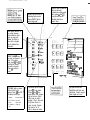
INTRODUCTION
Congratulations on your purchase of a DSC PC2000 Burglar Alarm Control
system. The PC2000 has been designed to give you the greatest possible
flexibility and convenience in the use of your security system. This booklet is
intended to serve as a handy reference and should be kept in a secure place.
Your security system consists of a number of different components. One
component is the DSC PC2000 control panel which will be mounted out of the
way in a utility room or basement. In addition to the main control electronics, the
control panel contains the standby battery and system fuses. There is normally
no reason for the user to have to access the control panel. The system also has
one or more keypads which will be mounted in convenient areas close to the
exit-entry doors. The keypads provide complete information about, and control
of, the security system. The security system has up to eight zones or areas of
protection. Each zone will be connected to one or more detection sensors such
as door or window contacts, motion detectors, glass break detectors or
vibration or shock sensors. The keypad zone lights are on when any sensor is
activated. The label provided for the inside of the keypad door can be used to
record which sensors are on each zone.
9
.
_‘.
4
IMPORTANT NOTICE
Digital Security Controls Ltd recommends that you read this manual carefully
and become familiar with the operation of your security system. Check with the
installing company to see which commands listed in this manual apply to your
particular security system. Fill out the system reference sheet and store this
booklet in a secure place for future reference.
It is important to test your system on a regular basis. To do this, first inform the
monitoring station that you are testing your system. Then, with the system
disarmed, activate all detection sensors one at a time and observe the zone
light come on at the keypad as each sensor is activated. Perform a bell test by
using the [x] 14) command. The PC2000 can be programmed at the time of
installation to automatically perform a test transmission to the monitoring station
on a regular basis. If this has not been done, check with the monitoring station
for instructions on how to perform a test transmission.
Check to see if the ‘TROUBLE’ light is on when arming the system and contact
the monitoring station if the trouble conditon cannot be cleared.
,
’ .’
- .
SYSTEMREFERENCE
Zone
Number
Protected Area
1
2
3
4
6
8
Keypad Zone [1].[3]
Keypad Zone [ *].[#I
Master Code Number
Programmed Code Numbers
Monitoring Stalion Information
Account #
Telephone #
Notes
PRINTED IN CANADA
COPYRIGHT 1966 DIGITAL SECURITY CONTROLS LTD.
1645 FLINT ROAD, DOWNSVIEW. ONTARIO CANADA M3J 2J6
Zone Type
MASTER CODE
The master security code is a 4 digit code which is supplied at the time of
installation. The master code is entered from the keypad and is used for arming
and disarming the security system, for programming additional security codes
and for changing other features. All keypad entries are made by pressing only
one key at a time, with exception of “KEYPAD ZONE” activation.
z
‘.
ARMING
.d*
Close all protected doors and windows and stop movement in areas covered by
motion detectors. If ‘SHUNT’ light is on, be sure zones are being intentionally
by-passed before arming the system (see ZONE BY-PASSING). Check to see
that the ‘READY’ light is on (all zones are closed). The system cannot be
armed unless the ‘READY’ light is on. Enter a [4 digit security code]. As each
digit is entered the keypad sounder will beep. The ‘ARMED’ light will come on
and the keypad sounder will beep quickly. If the security code was entered
incorrectly or the ‘READY’ light was not on, the keypad sounder wilt beep
steadily for 2 seconds. When the correct code is entered and the system is
armed, exit the premise through the designated exit-entry door. At the end of
the allowed exit time all lights on the keypad will go out except the ‘ARMED’
light. See the “PROGRAMMING OTHER SYSTEM FEATURES” section for
instructions on how to change the allowed exit time. Also see, QUICK-ARM
and AUTO-ARM.
DISARMING
Enter the premise through the designated exit-entry door. The keypad sounder
will be on. Go to the keypad and enter the [4 digit security code]. If an error is
made in entering the code, press the [#] key and enter the code again. The
‘ARMED’ light will go out and the keypad sounder will stpp. The correct security
code must be entered before the allowed entry time expires. To change the
entry time see “PROGRAMMING OTHER SYSTEM FEATURES”. If an alarm
occured while the panel was armed, the ‘MEMORY’ light and the ‘ZONE’ light
which caused the alarm will start to flash and stay flashing for 30 seconds.
ZONE BY-PASSING (SHUNTING)
Shunted zones do not cause an alarm. Use zone shunting when access is
needed to part of the protected area. Also, damaged wiring or contacts on a
zone may be temporarily shunted until repairs can be made so that the panel
can be armed.
’
To shunt zones, enler [ *I,[ 11 and the zone number(s) to be shunted. To remove
all shunts, enter [*],[l],[O]. The ‘ZONE’ lights which are on indicate shunted
zones. Press [#) to return lo ‘READY’(arm/disarm mode).
When the system is installed, the abilily to shunt certain zones may be
eliminated. In this case, the ‘ZONE’ lights for those zones will not come on in
response to the shunt command.
The ‘SHUNT’ light is on as long as at least one zone is shunted. Do not
unintentionally shunt zones when arming. Zone shunts are cancelled when the
panel is disarmed.
TROUBLE DISPLAY
The PC2000 continuously monitors a number of possible trouble conditions. If
one of these conditions occurs, the keypad ‘TROUBLE’ indicator will light.
Press the [XC] then [2] keys to display the type of trouble. The ‘ZONE’ lights
indicate the type of trouble condition.
I- DEFECTIVE STANDBY BATTERY
2- AC POWER FAILURE
3- BLOWN FUSE IN CONTROL PANEL
4- TELEPHONE LINE PROBLEM
5- UNSUCCESSFUL COMMUNICATION ATTEMPT WITH MONITORING
STATION
6- not used
7- BELL/SIREN CIRCUIT DEFECTIVE
8- MEMORY LOSS (USE MASTER CODE TO REPROGRAM)
Press the [#] to return to ‘READY’.
ALARM MEMORY DISPLAY
If the ‘MEMORY’ light is on an alarm has occured. The memory will be cleared
when the panel is re-armed.
Press the [*I then [3] keys to display which zone caused the alarm.
Press [#] to return to ‘READY’.
.
ARMED light will come on
indicating system armed.
Ensure READY light on,
enter 4 digit code.
MEMORY light on means an
alarm has occurred
To display zone that caused
alarm, press @I then &I.
Zone light will come on
indicating which zone
caused alarm.
ZONE light(s) when on in
the normal operating
mode indicate an open
zone. eg: open door,
window, etc. Refer to
zone chart on keypad
door for detailed zone
information.
SHUNT light will come 1
on when you by-pass a
zone. To by-pass a
zone, press 63 then ci3
and then the zone(s)
you wish to by-pass.
Press @I to return to
ready.
r
TROUBLE light on means
there is a fault on the
system. Press &I then q
to display trouble type:
1. Battery
5. Communicator
2. A.C. Power 6. Not used
3. Fuse
4. Telephone
line
7. Siren circuit
6. Power up
c
I
Program
PROGRAM light is on when
you pro ram user codes.
Press PI
* then @ then
enter Master Code, program
light will come on. Select
which code you wish to
program 1 thru 8, then enter
4 digit code. Press •I to
return to ready. Program
light must be “on” to
add or change user codes.
Ready tliht must be on. Enter code
ZONE BY-PAStNO:
Press @ then CT] keys. Presszones
to be by-passed. Press @ to return
to ‘Ready’.
AURM MEMORY:
i’ms.s &I then @j.
P@-MMMIN6 CODES:
Enter QD @I. master code 1 to 8
and new 4 dldt code.
’
KS SYWEht FltEQtJE~y
Key pad door has zone
identification and basic user
instructions. Protects keypad
when keypad not in use.
ALARM TEST
Press I*] lhen [4] for a 4 second lest of the keypad lights, keypad sounder and
sirens. This is a local lest only. A lest transmission to the monitoring station is
not done with this command.
PROGRAMMING ADDITIONAL SECURITY CODES
Enter [*I&] and [master security code]. The ‘PROGRAM’ light will flash and
the ‘ZONE’ lights will show which codes have already been programmed (up to
8 codes can be programmed from the keypad).
Press any key from (1 to 81 to indicate which one of the 8 codes is being
programmed. The ‘ZONE’ light will flash to indicate which code is being
programmed.
Enter a [4 digit security code]. At this point if [ * JC * xc] instead of a [4 digit code] is
entered, any previously programmed code in this localion will be eliminated.
To review:
programming a new code;
enter [*]$$[master code],(l to 8],[4 digit code].
eliminating an existing code;
enter [*],[5].[master code].[l to S],[xx-x-x]
Press [#] to return to ‘READY’.
SETTING AUTOMATIC ARMING TIME
The PC2000 can be programmed to automatically arm each day at the same
lime. To set the lime, enter (~1, (61 and a (4 digit security code]. Then enter any
[two digits] (from 01 to 23) for the number of hours until arming is to take place.
For example if it is 3:00 pm and auto-arming is to take place at 8:00 pm enter
05 for the five hours between 3:00 pm and 8:00 pm.
,..
*
_ -”
Press [#] to return to ‘READY’.
...
The [-K] [S] command is only used to set the arming time. The [x] [8] command
is used to turn on and off the auto-arm feature. See “PROGRAMMING
OTHER FEATURES”.
SPECIAL FUNCTION COMMAND
The PC2000 can be programmed at the time the system is installed to operate
other devices such as electric door strikes, door openers, electric lights,
cameras, etc. by a command from the keypad. This special function is activated
by pressing [s] then [7].
PROGRAMMING OTHER SYSTEM FEATURES
Before any of the following functions can be programmed, enter [*I, [8] and
[master code]. The ‘PROGRAM’ light will be flashing.
Press [l] then enter any [two digits] (from 01 to 99) to set the “ENTRY TIME” in
seconds. The “ENTRY TIME” is the time allowed between opening the
exit-entry door and entering the security code to disarm the PC2000.
Press [2] then enter any [two digits] (from 01 to 99) to set the “EXIT TIME” in
seconds. The “EXIT TIME” is the time allowed between arming the PC2000 and
exiting the exit-entry door.
Press [3] then enter any [two digits] (from 01 to 99) to set the “ALARM
CUT-OFF TIME” in minutes. The “ALARM CUT-OFF TIME” is the length of
time the siren or bells will ring before shutting off.
Press [4] to turn on the “QUICK-ARM” feature. The keypad sounder will beep
quickly 3 times. The “QUICK-ARM” feature allows entering [*I then [O] to arm
the PC2000 in place of a [4 digit code]. [x] [0] will not disarm the PC2000.
Pressing [4] again will turn off “QUICK-ARM”. The sounder will give one long
beep.
Press [5] to turn on the “AUTO-ARM” feature. The sounder will beep 3 times.
The “AUTO-ARM” leature arms the PC2000 at the same time each day. The
keypad sounder starts one minute before the programmed arming time (see [ *]
[6] command for programming “AUTO-ARM” time). The arming sequence may
be stopped by pressing any key. At the end of one minute the PC2000 will be
armed. Pressing [5] again will turn off “AUTO-ARM”. The sounder will give one
long beep.
Press [S] to turn on the “ALERT” feature. The sounder will beep 3 times. The
“ALERT” feature is used, while the panel is disarmed, to provide a tone from the
keypad each time a door or window is opened or closed. The specific doors and
windows which provide indication are determined at the time of installation.
Pressing [S] again will turn off the “ALERT”. The sounder will give one long
beep.
AUTO-TEST TRANSMISSION
The PC2000 can be programmed, at the time of installation, to send a test code
to the monitoring station at regular intervals. The frequency and time of test
transmissions is set by the monitoring station and should not be changed
without their knowledge.
DURESS CODE
The duress code feature must be programmed into the PC2000 at the time of
installation. When the duress code is used instead of a normal security code for
disarming, the system disarms as normal but a special duress code is sent to
the monitoring station. A duress code is created by adding 1 to the last digit of
any valid security code. When the duress code feature is used, the master
security code and the programmed security codes must not end in a 9. Also.
avoid programming a new security code which is the same number as another
duress code. This may cause a duress code to be transmitted when the new
code is used.
1234
Example: if normal security code is
then duress security code would be
1235
KEYPAD ZONES
There are two zones which can be activated from the keypad. One keypad
zone is activated by pressing the [l] and [3] keys at the same time. The
siren/bell output from this zone pulses on and off. This zone is annunciated by
the ‘ZONE 7’ light on the keypad. The other keypad zone is activated by
pressing the [x) and I#] keys at the same time. This zone generates a silent
alarm. There is no bell/siren signal and there is no annunciation from the
keypad. The only action is the transmission of a silent alarm code to the
monitoring station. Labels are included with the PC2000 keypad to identify the
two keypad zones.
LIMITED WARRANTY
i. .
Digital Security Controls Ltd. warrants that for a period of twelve months from the
date of purchase, the product shall be free of defects in materials and workmanship
under normal use and that in fulfillment of any breach of such warranty, Digital
Security Controls Ltd. shall, at its option, repair or replace the defective equipment
upon relurn of the equipment lo its factory. This warranly applies only to defecls in
parts and workmanship and not to damage incurred in shipping or handling, or
damage due to causes beyond the control of Digital Security Controls Ltd. such as
lightning. excessive voltage, mechanical shock, waler damage, or damage arising
out of abuse, alteration or improper application of the equipment.
The foregoing warranty shall apply only lo the original buyer, and is and shall be in
lieu of any and all other warranties, whether expressed or implied and of all other
obligations or liabilities on the part of Digital Security Controls Ltd. This warranty
contains the entire warranty. Digital Security Controls Ltd. neither assumes, nor
aulhorizes any other person purporling to act on its behalf lo modify or to change
this warranty, nor lo assume for it any other warranty or liability concerning this
product.
In no event shall Digital Security Controls Ltd. be liable for any direct, indirect or
consequential damages, loss of anticipated profits. loss of time or any other losses
incurred by the buyer in connection with the purchase, installation or operation or
failure of this product.
WARNING: Digital Security Controls Ltd. recommends that the entire system be
completely tested on a regular basis. However, despite frequenl testing. and due to,
but not limited to, criminal tampering or electrical disruption. it is possible for this
product to fail to perform as expected.
FCC COMPLIANCE
This equipmenl generates and uses radio frequency energy and if not installed and
used properly, in strict accordance with the manufaclurers inslruclions, may cause
interference to radio and television reception. It has been type tested and found to
comply with the limits for class “B” computing device in accordance with the specifications in Subpart “J” of Part 15 of FCC Rules, which are designed to provide
reasonable protection against such interference in any residenlial installalion.
However, lhere is no guarantee that interference will not occur in a particular
installation. If lhis equipment does cause interference to television or radio reception.
which can be determined by turning the equipment off and on, the user is encouraged lo try to correct the interference by one or more of the following measures:
Reorient the receiving antenna.
Relocate the computer with respect to the receiver.
Move the computer away from the receiver.
Plug the computer into a different outlet so that computer
and receiver are on different circuits.
If necessary, the user should consult the dealer or an experienced radio/television
technician for additional suggestions. The user may find lhe following booklet
prepared by the FCC helpful:
“How to identify and Resolve Radio/Television Interference Problems.” This booklel
is available from the U.S. Government Printing Oflice, Washington, DC. 20402,
Stock # 004-000-00345-4.