1
FACSIMILE EQUIPMENT
SERVICE MANUAL
MODEL: FAX1170/1270/1570MC
FAX1010/1020/1030
MFC1770/1870MC/1970MC
© Copyright Brother 1997
All rights reserved.
No part of this publication may be reproduced in any
form or by any means without permission in writing
from the publisher.
Specifications are subject to change without notice.
PREFACE
This publication is a Service Manual covering the specifications, construction, theory of operation, and maintenance of the Brother facsimile equipment. It includes information required for
field troubleshooting and repair—disassembly, reassembly, and adjustment—so that service
personnel will be able to understand equipment function, to rapidly repair the equipment and
order any necessary spare parts.
To perform appropriate maintenance so that the facsimile equipment is always in best condition
for the customer, the service personnel must adequately understand and apply this manual.
This manual is made up of six chapters and appendices.
CHAPTER I.
GENERAL DESCRIPTION
CHAPTER II.
INSTALLATION
CHAPTER III.
THEORY OF OPERATION
CHAPTER IV.
DISASSEMBLY/REASSEMBLY AND LUBRICATION
CHAPTER V.
MAINTENANCE MODE
CHAPTER VI.
ERROR INDICATION AND TROUBLESHOOTING
APPENDICES
Circuit Diagrams
This manual describes the model and its versions to be destined for major countries. The specifications
and functions are subject to change depending upon each destination.
CHAPTER I.
GENERAL DESCRIPTION
CONTENTS
1.
EQUIPMENT OUTLINE .................................................................................
I-1
1.1 External Appearance and Weight ...........................................................
I-1
1.2 Components ............................................................................................ I-1
2.
SPECIFICATIONS .......................................................................................... I-2
1. EQUIPMENT OUTLINE
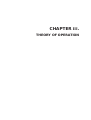
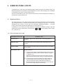
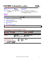
1.1
External Appearance and Weight
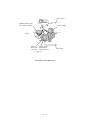
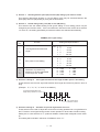
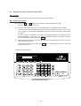
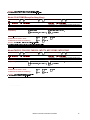
The figure below shows the equipment appearance and approximate dimensions.
(Unit: mm)
213 (H)
8.5" A4
A4 8.5"
Functio n
Tel/Inde
x Resolut
ion
Super
O. Scan
Mode
Help
IntelliFAX -1270
Hook
ABC
1
Hold
ause
02
09
#
Shift
21
10
22
Set
Sort
16
07
18
08
19
11
23
FACSIMILE
04
15
06
17
9
03
14
05
WXYZ
8
0
01
13
MNO
6
TUV
Speed Dial
*
3
JKL
5
PRS
7
PLAIN PAPER
DEF
2
GHI
4
Redial/P
Enlarge
/
Reduce
20
12
24
Copy
Stop
Start
Clear
385 (D)
* 317 mm for FAX1010 which has
no handset mount
385.5 (W)*
Weight: Machine proper
In package
1.2
FAX1010:
Approx. 5.0 kg (excluding a ribbon cartridge)
Other models: Approx. 5.2 kg (excluding a ribbon cartridge)
FAX1010:
Approx. 8.7 kg
Other models: Approx. 8.9 kg
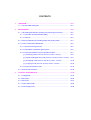
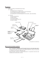
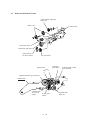
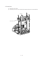
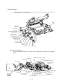
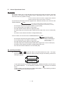
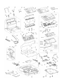
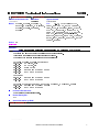
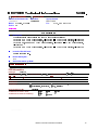
Components
The equipment consists of the following major components:
Recording paper cover ASSY
Control panel
ASSY
Handset
(Not provided on
the FAX1010)
Inner cover
Main cover
Handset mount
(Not provided on
the FAX1010)
Recording head
ASSY
Side cover
(Provided only on
the FAX1010)
Power supply PCB
Main frame
NCU PCB
Main PCB
Modular PCB
CIS unit
Bottom plate
Document
ejection tray
I–1
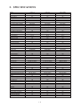
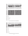
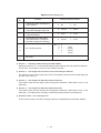
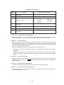
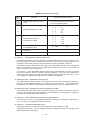
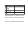
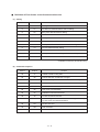
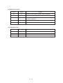
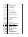
2. SPECIFICATIONS
Model
Color
Modem Speed
CCITT Group
Coding Method
Transmission Speed
Input/Output Width
ADF Capacity (pages)
Recording Paper Loadable
Paper Size
Ribbon Life (Letter-size print)
Handset
LCD Size
On-screen Programming
Gray Scale
Smoothing
One-touch Dial
Speed Dial
Telephone Index
FAX1170
Gray (1395)
9600 bps
G3
MH
15 sec.
8.5"/8.5"
20
200 sheets
Letter/Legal/A4
450 pages
Yes
16 x 1
Yes
64 by Dithered
Yes
12 x 2
26
Yes
FAX1270
White (1397)
9600 bps
G3
MH
15 sec.
8.5"/8.5"
20
200 sheets
Letter/Legal/A4
450 pages
Yes
16 x 1
Yes
64 by Dithered
Yes
12 x 2
36
Yes
FAX1570MC
White (1397)
14400 bps
G3
MH
9 sec.
8.5"/8.5"
20
200 sheets
Letter/Legal/A4
450 pages
Yes
16 x 1
Yes
64 by E/D
Yes
12 x 2
100
Yes
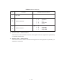
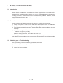
Multi-resolution Transmission
FAX/TEL Switch
Distinctive Ringing
Next Fax-reservation
Help
TAD Interface
Coverpage
Polling Type
Receive Password (password plus)
Delayed Transmission
Call Reservation
Call-back Message
Speaker Phone
Activity Report
Transmission Verification Report
Page Memory
Out-of-paper Reception
Quick Scan
Super Quick Scan
Broadcasting
ECM
Multi-transmission
Multi-copying w/Sorting
Enlargement/Reduction Ratio
TAD Type
OGM
ICM Recording Time
FAX Forwarding/Paging
FAX Retrieval
PCI (Missing link)
Message Center
Caller ID
Fax-/Voice-on-demand
Mail Box
Remote Control
Toll Saver
Memo/2-Way Recording
Auto Reduction
Confidential Mailbox
Optional Memory
Yes
Yes
Yes
Yes
Yes
Yes
Yes, Super
Sim/Del/Seq
Yes
3, timers
Yes
Yes
Monitor
Yes
Yes
512 KB (20 pages)
Yes
Yes
No
Yes
Yes
Yes
Yes
Yes (50-150%)
No
No
No
No
No
Ready
No
Yes
No
No
Yes
No
No
Yes
No
No
Yes
Yes
Yes
Yes
Yes
Yes
Yes, Super
Sim/Del/Seq
Yes
3, timers
Yes
Yes
Monitor
Yes
Yes
512 KB (20 pages)
Yes
Yes
No
Yes
Yes
Yes
Yes
Yes (50-150%)
No
No
No
Yes
Yes
Ready
No
Yes
No
No
Yes
No
No
Yes
No
No
Yes
Yes
Yes
Yes
Yes
Yes
Yes, Super
Sim/Del/Seq
Yes
3, timers
Yes
Yes
Yes, Full-duplex
Yes
Yes
1 MB (50 pages)
Yes
Yes
No
Yes
Yes
Yes
Yes
Yes (50-150%)
DSP
Yes
Yes, 30 min.
Yes
Yes
Ready
Yes
Yes
Voice-on-demand
Yes
Yes
Yes
Yes
Yes
No
No
I–2
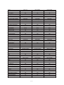
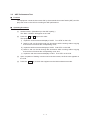
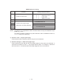
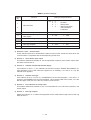
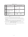
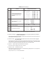
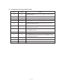
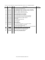
Model
Color
Modem Speed
CCITT Group
Coding Method
Transmission Speed
Input/Output Width
ADF Capacity (pages)
Recording Paper Loadable
Paper Size
Ribbon Life (A4-size print)
Handset
LCD Size
On-screen Programming
Gray Scale
Smoothing
One-touch Dial
Speed Dial
Telephone Index
FAX1010
White (1138)
9600 bps
G3
MH
15 sec.
A4/A4
20
200 sheets
Letter/Legal/A4
420 pages
No
16 x 1
Yes
64 by Dithered
Yes
12 x 2
36
Yes (Not Super)
FAX1020
White (1138)
9600 bps
G3
MH
15 sec.
A4/A4
20
200 sheets
Letter/Legal/A4
420 pages
Yes
16 x 1
Yes
64 by Dithered
Yes
12 x 2
36
Yes (Not Super)
FAX1030
White (1138)
14400 bps
G3
MH
10 sec.
A4/A4
20
200 sheets
Letter/Legal/A4
420 pages
Yes
16 x 1
Yes
64 by E/D
Yes
12 x 2
100
Yes (Not Super)
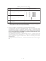
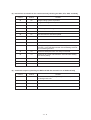
Multi-resolution Transmission
Yes
Yes
Yes
FAX/TEL Switch
Yes
Yes
Yes
Distinctive Ringing
Yes
Yes
Yes
Next Fax-reservation
Yes
Yes
Yes
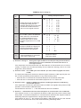
Help
Yes, Simple
Yes, Simple
Yes, Simple
TAD Interface
Yes
Yes
Yes
Coverpage
Yes, Super
Yes, Super
Yes, Super
Polling Type
Std/Sec/Del/Seq
Std/Sec/Del/Seq
Std/Sec/Del/Seq
Receive Password (password plus)
Yes
Yes
Yes
Delayed Transmission
3, timers
3, timers
3, timers
Call Reservation
Yes
Yes
Yes
Call-back Message
Yes
Yes
Yes
Speaker Phone
Monitor
Monitor
Yes, Full-duplex
Activity Report
Yes
Yes
Yes
Transmission Verification Report
Yes
Yes
Yes
Page Memory
512 KB (20 pages)
512 KB (20 pages)
1 MB (50 pages)
Out-of-paper Reception
Yes (20 pages)
Yes (20 pages)
Yes (50 pages)
Quick Scan
Yes (18 pages)
Yes (18 pages)
Yes (18 pages)
Super Quick Scan
No
No
No
Broadcasting
Yes, 60 locations
Yes, 60 locations
Yes, 124 locations
ECM
Yes
Yes
Yes
Multi-transmission
Yes
Yes
Yes
Multi-copying w/Sorting
Yes
Yes
Yes
Enlargement/Reduction Ratio
Yes (50-150%)
Yes (50-150%)
Yes (50-150%)
TAD Type
No
No
DSP
OGM
No
No
Yes
ICM Recording Time
No
No
Yes, 30 min.
FAX Forwarding/Paging
Yes/No
Yes/No
Yes
FAX Retrieval
Yes
Yes
Yes
PCI (Missing link)
Ready
Ready
Ready
Message Center
No
No
Yes
Caller ID
UK, Sw., Holland (Ready for France) UK, Sw., Holland (Ready for France) UK, Sw., Holland (Ready for France)
Fax-/Voice-on-demand
No
No
Voice-on-demand
Mail Box
No
No
Yes, 5
Remote Control
Yes
Yes
Yes
Toll Saver
No
No
Yes
Memo/2-Way Recording
No
No
Yes
Auto Reduction
Yes
Yes
Yes
Confidential Mailbox
No
No
No
Optional Memory
No
No
No
I–3
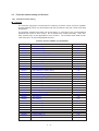
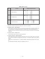
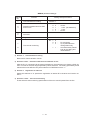
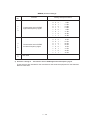
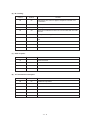
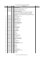
Model
Color
Modem Speed
CCITT Group
Coding Method
Transmission Speed
Input/Output Width
ADF Capacity (pages)
Recording Paper Loadable
Paper Size
Ribbon Life (Letter-size print)
Handset
LCD Size
On-screen Programming
Gray Scale
Smoothing
One-touch Dial
Speed Dial
Telephone Index
MFC1770
White (1138)
9600 bps
G3
MH
15 sec.
8.5"/8.5"
20
200 sheets
Letter/Legal/A4
450 pages
Yes
16 x 1
Yes
64 by Dithered
Yes
12 x 2
36
Yes
MFC1870MC
White (1138)
14400 bps
G3
MH
9 sec.
8.5"/8.5"
20
200 sheets
Letter/Legal/A4
450 pages
Yes
16 x 1
Yes
64 by Dithered
Yes
12 x 2
36
Yes
MFC1970MC
White (1138)
14400 bps
G3
MH
9 sec.
8.5"/8.5"
20
200 sheets
Letter/Legal/A4
450 pages
Yes
16 x 1
Yes
64 by E/D
Yes
12 x 2
100
Yes
Multi-resolution Transmission
FAX/TEL Switch
Distinctive Ringing
Next Fax-reservation
Help
TAD Interface
Coverpage
Polling Type
Receive Password (password plus)
Delayed Transmission
Call Reservation
Call-back Message
Speaker Phone
Activity Report
Transmission Verification Report
Page Memory
Out-of-paper Reception
Quick Scan
Super Quick Scan
Broadcasting
ECM
Multi-transmission
Multi-copying w/Sorting
Enlargement/Reduction Ratio
TAD Type
OGM
ICM Recording Time
FAX Forwarding/Paging
FAX Retrieval
PCI (Missing link)
Message Center
Caller ID
Fax-/Voice-on-demand
Mail Box
Remote Control
Toll Saver
Memo/2-Way Recording
Auto Reduction
Confidential Mailbox
Optional Memory
Yes
Yes
Yes
Yes
Yes
Yes
Yes, Super
Sim/Del/Seq
Yes
3, timers
Yes
Yes
Monitor
Yes
Yes
512 KB (20 pages)
Yes
Yes
No
Yes
Yes
Yes
Yes
Yes (50-150%)
No
No
No
Yes
Yes
Included (MFL3)
No
Yes
No
No
Yes
No
No
Yes
No
No
Yes
Yes
Yes
Yes
Yes
Yes
Yes, Super
Sim/Del/Seq
Yes
3, timers
Yes
Yes
Yes, Full-duplex
Yes
Yes
512 KB (20 pages)
Yes
Yes
No
Yes
Yes
Yes
Yes
Yes (50-150%)
DSP
Yes
Yes, 15 min.
Yes
Yes
Included (MFL3)
Yes
Yes
Voice-on-demand
Yes
Yes
Yes
Yes
Yes
No
No
Yes
Yes
Yes
Yes
Yes
Yes
Yes, Super
Sim/Del/Seq
Yes
3, timers
Yes
Yes
Yes, Full-duplex
Yes
Yes
1 MB (50 pages)
Yes
Yes
No
Yes
Yes
Yes
Yes
Yes (50-150%)
DSP
Yes
Yes, 30 min.
Yes
Yes
Included (MFL3)
Yes
Yes
Voice-on-demand
Yes
Yes
Yes
Yes
Yes
No
No
I–4
CHAPTER II.
INSTALLATION
CHAPTER III.
THEORY OF OPERATION
CONTENTS
1.
OVERVIEW ..................................................................................................... III-1
1.1 Functional Block Diagram ......................................................................
2.
III-1
MECHANISMS ................................................................................................ III-2
2.1 Transmitting Mechanism (Feeding and scanning documents) ...............
III-2
2.1.1 Automatic document feeder (ADF) ..................................................
III-2
2.1.2 Scanner ........................................................................................... III-3
2.2 Receiving Mechanism (Feeding paper and printing data) ......................
III-4
2.3 Power Transmission Mechanism ...........................................................
III-5
2.3.1 Structure of the gear train ...............................................................
III-5
2.3.2 Description of planetary gear system ..............................................
III-6
2.3.3 Power transmission for four operation modes .................................
III-7
[ 1 ] Scanning mode (Solenoid: OFF, Motor rotation : Reverse) ......................
III-8
[ 2 ] Paper feeding/ejection mode (Solenoid: ON, Motor rotation : Reverse) III-9
3.
[ 3 ] Recording mode (Solenoid: OFF, Motor rotation : Forward) ....................
III-10
[ 4 ] Copying mode (Solenoid: ON, Motor rotation : Forward) .........................
III-12
2.3.4 Power transmission route ...............................................................
III-14
2.4 Sensors and Actuators ...........................................................................
III-16
CONTROL ELECTRONICS ...........................................................................
III-19
3.1 Configuration ........................................................................................... III-19
3.2 Main PCB ................................................................................................ III-20
3.3 NCU PCB ................................................................................................ III-27
3.4 Control Panel PCB .................................................................................
III-29
3.5 Power Supply PCB ................................................................................
III-30
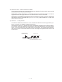
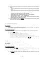
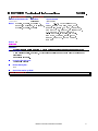
1. OVERVIEW
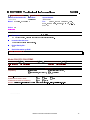
1.1
Functional Block Diagram
Control Panel
Recorder
LCD
Recording head
Ribbon sensor
Document
ejection tray
Modular PCB
(Cover sensor)
Scanner
Main PCB
CIS unit
(Document front
and rear sensors)
Ribbon cartridge
To PC
Main frame
NCU PCB
Line
Power supply
PCB
AC
Motor
Sensor PCB
(Paper-edge
sensor and paper
ejection sensor)
Handset
Hook switch
sensor
III – 1
2. MECHANISMS
The equipment is classified into the following mechanisms:
■ Transmitting Mechanism
Feeding and scanning documents
■ Receiving Mechanism
Feeding paper and printing data
■ Power Transmission Mechanism
Switching the power transmission route
■ Sensors and Actuators
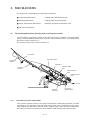
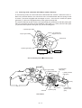
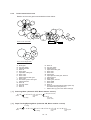
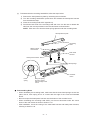
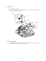
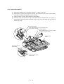
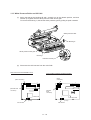
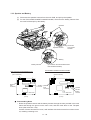
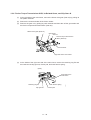
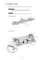
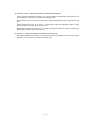
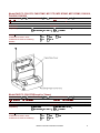
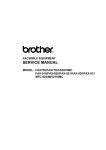
2.1
Transmitting Mechanism (Feeding and scanning documents)
The transmitting mechanism consists of the document stacker, automatic document feeder
(ADF), document feeding related rollers, scanner, and document sensors. (For details about
the sensors, refer to Section 2.4.)
For the drive power source, refer to Section 2.3.
Document
Separation roller
Document
support
ADF parts
Pressure roller,
rear
Document
stacker
White pressure
roller
Pressure roller,
front
(Front)
Scanner
(CIS unit)
2.1.1
Document
ejection roller
Automatic document feeder (ADF)
If the operator sets documents on the stacker and starts the transmitting operation, the ADF
(consisting of the separation roller and ADF parts) feeds those documents into the equipment, starting from the bottom sheet to the top, page by page. Each document advances to
the scanner, and then it is fed with the white pressure roller and document ejection roller.
III – 2
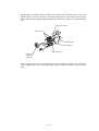
2.1.2
Scanner
The scanner uses a contact image sensor (CIS) unit which consists of an LED array illuminating documents, a self-focus lens array collecting the reflected light, a CIS PCB carrying
out photoelectric conversion to output picture element data, and a cover glass on which a
document advances. When the document passes between the white pressure roller and the
cover glass, it is scanned.
III – 3
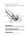
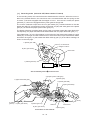
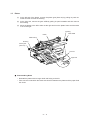
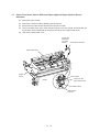
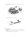
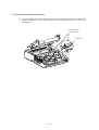
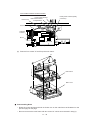
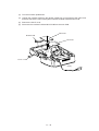
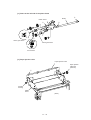
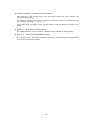
2.2
Receiving Mechanism (Feeding paper and printing data)
The receiving mechanism consists of the recording paper cover ASSY, paper feed roller
ASSY, platen, thermal recording head, paper ejection roller, and sensors. (For details about
the sensors, refer to Section 2.4.)
Paper
Paper feed roller ASSY
Chute ASSY
Recording
paper cover
ASSY
Paper ejection roller
Platen
(Front)
Thermal ink ribbon
Recording head
STEP 1: In the paper feeding mode
If the equipment receives data, the control electronics activates the solenoid and rotates the
motor counterclockwise to drive the paper feed roller (and paper ejection roller). This pulls in
a sheet of paper and feeds it until its leading edge reaches the point just before the printing
position.
STEP 2: In the recording (platen drive & ribbon take-up) mode
The control electronics deactivates the solenoid and rotates the motor clockwise to drive the
platen gear and the ribbon take-up gear as well as the paper ejection roller. This feeds the
paper up to the printing position where the thermal recording head prints, as well as feeding
the thermal ink ribbon.
STEP 3: In the paper ejecting mode
The same operation as for STEP 1 takes place so as to eject the paper.
III – 4
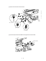
2.3
Power Transmission Mechanism
The equipment has a single drive motor whose power transmission route can be switched by
the planetary gear systems and the solenoid. This switching allows the equipment to function in four operation modes (scanning, paper feeding/ejecting, recording, and copying
modes). For the details about the planetary gear systems, refer to Subsection 2.3.2.
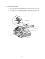
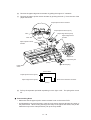
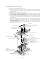
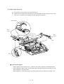
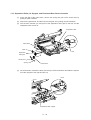
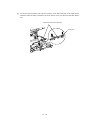
2.3.1
Structure of the gear train
At the left side of the equipment, the rotational torque of the motor on the main frame is
transmitted to the gears on the main frame and then to the gears on the platen frame. These
gears drive the document feeding/ejecting related rollers, paper feeding/ejecting related rollers, and the platen.
If the platen gear ("a" in the figure below) on the left end of the platen shaft rotates, the gear
33RB ("b") on the right end also rotates. This way, the rotational torque is transmitted to the
gears on the right side of the equipment.
At the right side of the equipment, the rotational torque is further transmitted via the friction
torque transmission ASSY to the ribbon drive gear ("e") which drives the ribbon take-up gear
in the ribbon cartridge.
Right side
d (Gear 18)
e (Gear 46 of Friction torque
transmission ASSY)
c (Gear 20/40)
Main frame
b (Gear 33RB)
Platen frame
e (Ribbon drive gear, Gear 24)
Left side
(Gears 18/41)
V
W (Clutch gear ASSY)
X (Paper ejection roller gear, Gear 40)
U
a (Platen gear, Gear 23)
Z (Gear 33/45)
T (Paper feed roller gear, Gear 55)
M (Gear 39)
Platen frame
C (Planet gear 20B of Arm B ASSY)
D (Gear 33)
F (Separation roller gear)
I (White pressure
roller gear)
S (Planet gear
34 of Arm P
ASSY)
(Front)
R (Sun gear
39/24)
O (Gear 39)
Main frame
Q (Gear 33)
P (Gear 18)
N (Sun gear
36/27)
Y (Planet gear 44 of
Arm C ASSY)
B (Sun gear 20/90)
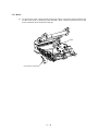
Gear Train
III – 5
E (Gear
20/40)
G H
K (Document
ejection roller
J gear)
(Gears 14/20)
Clutch lever
A (Motor gear)
L (Planet gear 20A of Arm A ASSY)
: Gears on the main frame
: Gears on the platen frame
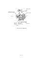
2.3.2
Description of planetary gear system
The equipment uses the following three planetary gear systems:
- Sun gear 20/90 ("B" in the figure given on the previous page) and its planet gears
- Sun gear 36/27 ("N") and its planet gear
- Sun gear 39/24 ("R") and its planet gear
This section describes the planetary gear system of the sun gear 20/90 ("B"). It consists of
the sun gear 20/90, two planet gears 20, arm A, and arm B, as shown below.
Planet gear 20B
Arm B
Sun gear 20/90
Arm A
Motor gear
Planet gear 20A
Planetary Gear System
If the motor rotates, the sun gear 20/90 rotates so that the rotational torque is transmitted to
the engagement between the sun gear and the planet gears 20. Since the arms and planet
gears are so designed that the moment of the arms is less than that of the planet gears, the
arms turn around the center shaft in the same direction as the sun gear 20/90.
If the planet gear(s) becomes engaged with any other gear so that the arm cannot turn furthermore, the rotational torque of the sun gear 20/90 is transmitted to that planet gear. Accordingly, the planet gear starts rotation in the opposite direction of the sun gear 20/90.
III – 6
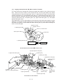
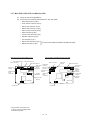
2.3.3
Power transmission for four operation modes
Depending upon the solenoid ON/OFF state and the motor rotation direction, the planetary
gear train switches the power transmission route for the four operation modes.
Solenoid ON/OFF state
Motor rotation direction
Solenoid: OFF
Section y (to block the
stoppper of arm B)
Planet gear 20B
Stopper of
arm B
Clutch lever
Arm B
Cutout x (engaged
with the stopper of
arm A)
Solenoid
Sun gear
20/90
Spring
Planet gear
20A
Solenoid: ON
Section y (to block the
stoppper of arm B)
Clutch lever
Cutout x (engaged
with the stopper of
arm A)
Solenoid
Forward
Reverse
Spring
III – 7
Stopper
of arm A
Arm A
Motor
gear
[1]
Scanning mode (Solenoid: OFF, Motor rotation: Reverse)
In the scanning mode, the control electronics deactivates the solenoid. When the motor rotates in the reverse direction, the clutch lever turns counterclockwise with the spring so that
its cutout x becomes engaged with the stopper of arm A. Once arm A is locked, the planet
gear 20A ("L") will not be engaged with any other gear but simply idle.
The motor's rotational torque turns the sun gear 20/90 ("B") clockwise so that the planet gear
20B ("C") transmits the torque to the separation roller gear ("F"), white pressure roller gear
("I") and document ejection roller gear ("K") via the several gears.
C (Planet gear 20B)
Cutout x of clutch lever
Stopper of arm A
B (Sun gear 20/90)
Clutch lever
L (Planet gear 20A)
Solenoid
Arm A Locked by Cutout x of Clutch Lever
B (Sun gear 20/90)
C (Planet gear 20B)
F (Separation
roller gear)
I (White pressure
roller gear)
D
G
L
Solenoid
Active Gears
III – 8
E
Clutch lever
A (Motor gear)
H
J
(Front)
K (Document
ejection roller
gear)
[2]
Paper feeding/ejecting mode (Solenoid: ON, Motor rotation: Reverse)
In the paper feeding/ejecting mode, the control electronics activates the solenoid to release
the stopper of arm A. When the motor rotates in the reverse direction, the sun gear 20/90
("B") rotates clockwise so that the planet gear 20A ("L") transmits the torque via the gear 39
("M") and other gears to the paper feed roller gear ("T") and paper ejection roller gear ("X").
Since the stopper of arm B is blocked by the section y of the clutch lever, the planet gear
20B ("C") is merely idle without engaging with any other gear.
Stopper of arm B
C (Planet gear 20B)
Section y of clutch lever
Stopper of arm A
B (Sun gear 20/90)
Clutch lever
L (Planet gear 20A)
Solenoid
Arm B Blocked by Section y of Clutch Lever
X (Paper ejection roller gear)
T (Paper feed roller gear)
U
V
B (Sun gear 20/90)
W
C
Q
P
O
S (Planet
gear 34)
Y
N
M
(Front)
R (Sun gear 39/24)
L (Planet gear 20A)
Solenoid
Clutch lever
A (Motor gear)
Active Gears
III – 9
[3]
Recording mode (Solenoid: OFF, Motor rotation: Forward)
In the recording mode, the control electronics deactivates the solenoid. When the motor rotates in the forward direction, the clutch lever turns counterclockwise with the spring so that
its cutout x becomes engaged with the stopper of arm A. Once arm A is locked, the planet
gear 20A ("L") will not be engaged with any other gear but simply idle.
The motor's rotational torque turns the sun gear 20/90 ("B") counterclockwise so that the
planet gear 20B ("C") transmits the torque via the gear 39 ("M") and other gears to the platen
gear ("a") as well as the paper ejection roller gear ("X").
The platen advances recording paper and its paper movement rotates the paper feed roller.
Consequently, the paper feed roller shaft rotates faster than the paper feed roller gear ("T").
If the platen gear ("a" in the figure below) on the left end of the platen shaft rotates, the gear
33RB ("b") on the right end also rotates so as to drive the friction torque transmission ASSY
and ribbon drive gear ("e") that rotates the ribbon take-up gear ("f") in the ribbon cartridge, as
shown on the next page.
C (Planet gear 20B)
Cutout x of clutch lever
Stopper of arm A
B (Sun gear 20/90)
Clutch lever
L (Planet gear 20A)
Solenoid
Arm A Locked by Cutout x of Clutch Lever
X (Paper ejection roller gear)
a (Platen gear)
T (Paper feed roller gear)
U
V
C (Planet gear 20B)
B (Sun gear 20/90)
W
Z
Q
O
P
M
L
(Front)
S (Planet
gear 34) R (Sun gear 39/24)
Y (Planet gear 44)
Solenoid
Clutch lever
N (Sun gear 36/27)
A (Motor gear)
Active Gears on the Left Side
III – 10
Platen frame
f (Ribbon take-up gear
in the ribbon cartridge)
b (Gear 33RB)
(Front)
c
d
Ribbon
drive gear
(Gear 24)
Friction torque
transmission
ASSY (Gear 46)
Main frame
e
Active Gears on the Right Side
III – 11
[4]
Copying mode (Solenoid: ON, Motor rotation: Forward)
The control electronics activates the solenoid to release the stopper of arm A from the clutch
lever. When the motor rotates in the forward direction, the sun gear 20/90 ("B") rotates
counterclockwise so that the planet gear 20A ("L") transmits the torque to the document
scanner mechanism (e.g., the separation roller gear ("F"), white pressure roller gear ("I") and
document ejection roller gear ("K")) and the planet gear 20B ("C") transmits the torque to the
recording mechanism (e.g., the platen gear ("a"), paper feed roller gear ("T"), and paper
ejection roller gear ("X")).
If the platen gear ("a" in the figure below) on the left end of the platen shaft rotates, the gear
33RB ("b") on the right end also rotates so as to drive the friction torque transmission ASSY
and ribbon drive gear ("e") that rotates the ribbon take-up gear ("f") in the ribbon cartridge, as
shown on the next page.
Stopper of arm B
Stopper of arm A
C (Planet gear 20B)
Cutout x of clutch lever
B (Sun gear 20/90)
Clutch lever
L (Planet gear 20A)
Solenoid
Arm A Released from Coutout X of Clutch Lever
X (Paper ejection roller gear)
a (Platen gear)
T (Paper feed roller gear)
U
C (Planet gear 20B)
V
F (Separation roller gear)
W
a
Q
I (White pressure
roller gear)
Z
O
P
G
M
L
E
H
J
(Front)
S (Planet
gear 34) R (Sun gear 39/24)
Y (Planet gear 44)
N (Sun gear 36/27)
B (Sun gear
20/90)
Solenoid
Clutch lever
A (Motor gear)
L (Planet gear 20A)
Active Gears on the Left Side
III – 12
K (Document
ejection roller
gear)
Platen frame
f (Ribbon take-up gear
in the ribbon cartridge)
b (Gear 33RB)
(Front)
c
d
Friction torque
transmission
ASSY (Gear 46)
Ribbon
drive gear
(Gear 24)
e
Active Gears on the Right Side
III – 13
Main frame
2.3.4
Power transmission route
Rotation of the motor gear is transmitted as shown below.
U
V
X
T
W
S
a
R
Z
D
F
C
Q
O
P
I
G
B
N
Y
L
M
A
H
J
E
K
Gears on the Left Side
b
f
c
e
d
Gears on the Right Side
A:
B:
C:
D:
E:
F:
G:
H:
I:
J:
K:
L:
M:
N:
O:
P:
Motor gear
Sun gear 20/90
Planet gear 20B
Gear 33
Gear 20/40
Separation roller gear
Gear 14/20
Gear 14/20
White pressure roller gear
Gear 14/20
Document ejection roller gear
Planet gear 20A
Gear 39
Sun gear 36/27
Gear 39
Gear 18
Q:
R:
S:
T:
U:
V:
W:
X:
Y:
Z:
a:
b:
c:
d:
e:
f:
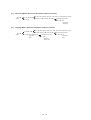
[1]
Scanning Mode (Solenoid: OFF, Motor rotation: reverse)
A➜B
(Motor)
C➜D➜E➜F➜G➜H
L (Idling)
[2]
Gear 33
Sun gear 39/24
Planet gear 34
Paper feed roller gear
Gear 18/41
Gear 18/41
Clutch gear
Paper ejection roller gear, Gear 40
Planet gear 44
Gear 33/45
Platen gear, Gear 23
Gear 33RB
Gear 20/40
Gear 18
Friction torque transmission ASSY (Gear 46)
and ribbon drive gear (Gear 24)
Ribbon take-up gear in the ribbon cartridge
(Separation
roller)
I (White pressure roller)
J➜K
(Document
ejection roller)
Paper Feeding/Ejecting Mode (Solenoid: ON, Motor rotation: reverse)
C (Idling)
A➜B
(Motor)
L➜M➜N
O➜P➜Q➜R➜S➜T➜U➜V➜W➜X
(Paper feed
roller)
Y (Idling)
III – 14
(Paper ejection
roller)
[3]
Recording Mode (Solenoid: OFF, Motor rotation: forward)
A➜B
(Motor)
C➜M➜N
L (Idling)
Y ➜ Z ➜ a (Platen) ➜ b ➜ c ➜ d ➜ e ➜ f (Ribbon take-up gear)
O➜P➜Q➜R➜S➜W
X (Paper ejection roller)
V➜U➜T
(Paper feed
roller, Idling)
[4]
Copying Mode (Solenoid: ON, Motor rotation: forward)
C➜M➜N
A➜B
(Motor)
Y ➜ Z ➜ a (Platen) ➜ b ➜ c ➜ d ➜ e ➜ f (Ribbon take-up gear)
O➜P➜Q➜R➜S➜W
L ➜ E ➜ F➜ G ➜ H
(Separation
roller)
I (White pressure roller)
J➜K
(Document
ejection roller)
III – 15
X (Paper ejection roller)
V➜U➜T
(Paper feed
roller)
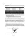
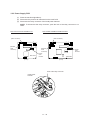
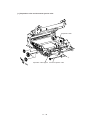
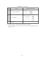
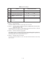
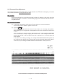
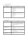
2.4
Sensors and Actuators
This equipment has four photosensors and three mechanical switches (two for the FAX1010)
as described below.
Sensor name
Type
Located on
Document front sensor
Document rear sensor
Photosensor (PH1)
Photosensor (PH2)
Main PCB
Main PCB
Paper ejection sensor
Paper-edge sensor
Photosensor (PH1)
Photosensor (PH2)
Sensor PCB
Sensor PCB
Cover sensor
Mechanical switch (SW1)
Modular PCB
Ribbon sensor
Mechanical switch (SW1)
Recording head
Hook switch sensor*
Mechanical switch (SW1)
Hook switch PCB
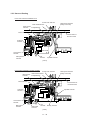
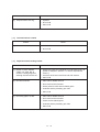
•
Document front sensor which detects the presence of documents.
•
Document rear sensor which detects the leading and trailing edges of pages to tell the
control circuitry when the leading edge of a new page has reached the starting position
and when the scan for that page is over.
•
Paper ejection sensor which detects whether a paper jam has occurred.
•
Paper-edge sensor which detects the leading and trailing edges of paper and the presence of paper as well as detecting whether the paper front cover is closed.
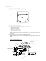
These photosensors are of a reflection type consisting of a light-emitting diode and a lightsensitive transistor. Each of them has an actuator separately arranged (see the next page),
except that the paper-edge sensor has two actuators for sensing the paper and the paper
front cover. When an actuator is not activated, its white end lies in the path of light issued
from the light-emitting diode and reflects its light so that the reflected light enters the lightsensitive transistor. If a document or paper comes in so as to activate the actuator, the
actuator's white end goes out of the light path and no reflected light enters the light-sensitive
transistor. This way, the sensor detects the presence of documents or paper.
•
Cover sensor which detects whether the recording paper cover ASSY is closed.
•
Ribbon sensor which detects whether the ink ribbon is loaded.
•
Hook switch sensor* which detects whether the handset is placed on the handset mount.
The cover sensor has an actuator separately arranged (see page III-18). If the actuator is
activated, its lower end releases the cover sensor lever so that the sensor signals the detection.
Path of actuator's end
Approx. 0.7 mm
Glass
Lightemitting
diode
* Not provided on the FAX1010
III – 16
Lightsensitive
transistor
(Front)
Document rear sensor
Document rear sensor actuator
Document front sensor
Document front sensor actuator
Main PCB
Paper-edge sensor actuator
Paper-edge sensor
Paper ejection sensor
actuator
Paper ejection sensor
Front cover
sensing actuator
(Front)
Sensor PCB
Recording head
Ribbon sensor
Ribbon sensor actuator
Location of Sensors and Actuators (1)
III – 17
Cover sensor actuator
Cover sensor
Cover sensor lever
Modular PCB
Hook switch sensor actuator**
Hook switch sensor**
Hook switch PCB**
Handset mount*
Location of Sensors and Actuators (2)
* Not provided on the FAX1010
** Not provided on the FAX1010 or those versions equipped with a Binatone handset
III – 18
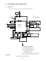
3. CONTROL ELECTRONICS
3.1
Configuration
The hardware configuration of the facsimile equipment is shown below.
Line
External
telephone
2-pin
Handset*
(Note)
12-pin: U.S.A. versions
18-pin: European versions
2-pin
4-pin
NCU PCB
(Note)
2
Modular*
PCB
PC I/F
Speaker
P2
8-pin
Main PCB
*1
14-pin
COG
5-pin
Control
panel PCB
2-pin
6-pin
Motor
7-pin
ASIC
14-pin
CIS unit
2-pin
Solenoid
FPC key
11-pin
5-pin
2-pin
*3
Sensor
PCB
*
Hook *4
switch
PCB
2-pin
2-pin
4-pin
Microphone
Ni-MH
battery
(Only on the FAX1570MC/1030/MFC1870MC/1970MC)
*5
Recording head
4-pin
Power supply PCB
*1 On the main PCB are these sensors:
• Document front sensor (PH1)
• Document rear sensor (PH2)
*2 On the modular PCB is the cover sensor.
*3 On the sensor PCB are these sensors:
• Paper ejection sensor (PH1)
• Paper-edge sensor (PH2)
*4 On the hook switch PCB* is the hook switch sensor (SW1).
*5 On the recording head is the ribbon sensor (SW1).
* Not provided on
the FAX1010
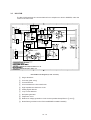
Configuration of Facsimile Equipment
III – 19
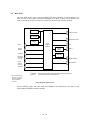
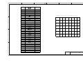
3.2
Main PCB
The main PCB, which is the nucleus controlling the entire operation of the equipment, consists of a FAX engine (ASIC), memories, MODEM, motor drive circuitry, sensor detection circuitry, and analog circuits for scanning, recording, and power transmission shifting.
ROM
Control panel
E2PROM
Recording head
DRAM
FAX
engine
NCU
CIS
(ASIC)
Motor
driver
Power
supply
Speaker
Motor
Sensors
Modular
PCB (for
PC I/F)
Ni-MH battery
Hook
switch
sensor*
Microphone
Sensors
E2PROM:
DRAM:
** Not provided on the
FAX1010 or those
versions equipped
with a Binatone
handset
Electrically Erasable Programmable Read-only Memory
Dynamic Random Access Memory
Block Diagram of Main PCB
On the following pages, the main PCB circuit diagrams are described on the basis of the
FAX1570MC/1030/MFC1870MC/1970MC.
III – 20
1
2
3
4
5
5
6
7
8
+ 5 V
Q6
L 3
0
RH5 V A 4 3
RS T L
R9 0
1 6 A , 4 7 B , 1 4 B , 5 7 E
# 9
T 7 D6 0
1 . 5 K
V CC
4 4
OUT
GND
A
F G
RV DD
C6 5
1 4 3
CC1 0 4
E X T L
1 4 1
R8 0
GND
+ 5 V
X T 1
C S A 1 6 MX
R8 2
2 5 D
RA S
0
2 5 D
CA S
1 0 0
R1 1 4 1 0 0
C6 1
C6 2
CC3 0 P
CC3 0 P
2 7 B
R MR D
2 7 B
R OMC
7 5
*
1 5 B
1
3
R9
1 5 B
S DOT
1 5 B
S DI N
2
GND
P CL K
4 7 0
2
1 2 B
R8 4
B 5 B - P H
WH I T E
C1 4
C1 5
C1 0 1 C1 0 1
P CL K
S DOUT
1 2 B
7 3
RS T L
GND
CC1 0 2 B
C6 7
4 2 F
DA S NO
DA RE C
R1 3 2
2 0 0
R5 9
1 0 k
R6 8
1 0 k
1 8
1 9
2 0
5 2 C
CL B S Y
5 2 D CL RX S
R1 3 3
1 0 k
L 5 V
C
C5 0
C3 8
C7 0
4 3 B
T A DH
0
0
CC1 0 4
4 4 D
T X S L
4 5 D
HA F H
2 1
2 2
2 3
2 4
2 5
2 0 5
+ 5 V
GND
M I O 0 ( P WM )
M I O 1 ( P WM )
M I O 2 ( P WM )
A D P D MD
A A P D MD
D P D MD T
MI O3
D P D MC K
MI O4
A P D MC K
MI O5
A P D MD T
MI O1 1
C5
MI O1 2
C4
MI O1 3
C3
MV D D
C2
C1
C3 9
C0
CC1 0 4
2 0 8
GND
2 0 4
MV S S
MON MD C K
A MU T E
MU T E
GND
1 6
R8 6
*
1 0 3
L I G T ( P WM )
ME X T L
MT X L
4 6 E
3 2 F
*
3 8 C
4 2 F
3 7 B
D
3 7 B
GND
E 5 V
+ 5 V
S P ON
RI B ON
F RNT
T L OF 2
F S E N
RS E N
1 7 B
CS E N
3 8 C
RE A R
8 0
7 6
7 7
7 8
1 4
A A MD
R6 7
1 2
2 0 0
7 9
3 0
3 1
3 2
S E N2
DA 0
S E N3
DA 1
S E N4
DA 2
S E N5
DA 3
S E N6
DA 4
S E N7
DA 5
S E N8
DA 6
DA 8
3 2 E
S T 1
3 2 E
S T 2
3 2 E
HDC
3 2 E
DI N
3 2 E
DOUT
9 2
9 1
9 3
9 4
9 0
S T 1
R6 6
3 0 0
D MK
R6 4
3 0 0
A MK
8
A MT
DA 9
7
3
C3
3 4 C
E 1 CS
3 4 C
S MC
3 6 C
RDA T
+ 2 6 V
2 3 C
MT I 1
2 3 C
MT I 0
3 2 A
RB
1 0 6
1 0 7
1 0 2
9 5
9 8
9 9
R9 6
3 7 D
7 5 K
S E ON
1 0 0
1 0 1
1 0 4
3 4 C, 3 2 A
T G
D0 1
DOUT
D0 2
E 1 CS
D0 5
S P S L ( S MC )
D0 6
RDA T
D0 7
CL 2
V DD
CL 1
V DD
CL B
V DD
RB
V DD
DI F
T G
V DD
V DD
V DD
5 2
R9 5
C7 9
3 3 B
CC1 0 4
3 3 D
E A T
4 2 B , 3 8 E
C ML H
4 2 E
RDP S
V I D
5 6
5 5
CP 3 I
5 4
5 3
E 0 V
RDA 6 1
V DD
CP 1 I
V DD
2
C4
1
C5
6
C0
5
N MI
8
C2
1 3
1 8 7
1 8 8
1 8 9
A MU T
4 6 E
V OL 3
4 6 D
RNGL
4 2 D
OT O
B S A K
( OD)
B S RQ
P WO N
WA I T
C ML
RF S H
DP S
M1
T E L
1 9 2
HOOK
1 9 3
CI
1 9 4
1
A 0
A 1
A 2
T L OF
1 9 5
3 9
4 0
A 3
S T D
A 4
RI NG
A 5
S P ON
1 8 4
A 6
E 2 CS
2 0 3
A 7
CT X D
A 8
MU T
7
2 0 7
L 2
A 9
4 8 A , 5 8 D
4
2 0 6
1 0 9
1 1 0
1 1 1
1 1 2
1 1 3
2 0 0
R1 1 8
2 0 0
RA 2
2 0 0
V S S
CP NN
V S S
V S S
5 0
5 1
E 5 V
5 8
R9 3
1 0 0 F
4 9
F
4 8
4 7
R9 4
C7 8
C7 7
C7 6
C7 3
7 5 F
CC1 0 4
CC1 0 4
CC1 0 4
CC1 0 4
5 9
3 2 F
8 9
L A T C
1 8 5
C L MP
3 3 C
P O1
P O2
1 8 6
C P WM
A 1 1
P 0 3
A 1 2
( OD)
A 1 3
DA 0
A 1 4
DA 1
R6 0
4
4 . 7 K
DA 2
DA 3
R6 1
DA 4
2 2 0
A 1 5
5 3 B
2 5 B
X T 2
2 6
CL S E L
2 7
E P CK
2 3 F
S OL
3 8 E
P WO N
2 8
D5 7 . 6 D6
DA 5
R M1
MA 1 6
R M2
MA 1 7
R M3
2 9
RA 1
2 0 0
MA 1 8
ODP I O0
DA 7
C4 2
DA 8
C4 1
CC5 P
CC5 P
R7 9
*
R7 8
*
ODP I O1
1 8 2
GND
DA 9
1 2 0
1 2 7
D0
1 2 8
D1
1 2 9
D2
1 3 0
D3
1 3 1
D4
1 3 3
D5
1 3 4
D6
1 3 5
D7
CK S
1 9 6
T X D
1 9 7
RX D
1 9 8
CT S
8 4
MM1
C- 0 0 1 R
C7 5
3 4 C
2 6 B , 2 6 E
1 8 3
1 0 8
S RA M
2 5 B
E P DO
2 3 E
MT V R
P I O1
ODP I O2
P I O2
ODP I O3
P I O3 ( S R A M) OD P I O4
4 1
C0 V
8 5
MM2
8 6
MM3
6 9
P I O5
F DCL K
P I O6
F DOUT
F DI N
R1 3 1
F CS 1
1 0 K
CC1 2 P
8 7
MM4
1 7 B
GND
P CI
+ 5 V
2 3 C
3
4 5
L 5 V
1 6 B
4 6
1 2 5
I ORQ
1 2 6
MR E Q
1 4 0
CK 1 6
R8 3
P B US
+ 5 V
1 0 K
8 8
P 7
6
5
RX D
1 4 4
R8 1
2 0 0
1 4 5
RD
1 4 6
WR
B
9
4
R1 0
CT S
4 . 7 K
1 2 D
RB US
1 6 8
2
CS E N
8
3 4 D
7
C1 7
1 6 9
*
1 7 0
GND
1 7 1
P 1 5
I MS A - 9 1 1 0 S - 0 8 L
1 7 2
GND
1 7 3
1 7 4
1 3 6
A 0
1 3 7
A 1
1 3 8
A 2
C
+ 5 V
1 3 9
A 3
1 4 8
A 4
R1 1
L 5
1 4 9
A 5
4 . 7 K
MMZ Y 6 0 1 B
1 5 0
A 6
1 5 1
1 5 C
HOOK
HOOK
1
A 7
1 5 2
A 9
1 5 4
A 1 0
1 5 5
A 1 1
2
C1 8
A 8
1 5 3
:
CC1 0 1
GND
P 1 4
B 2 B - P H
GND
1 5 7
WH I T E
1 5 8
A B US
1 5 9
2 6 B , 3 4 D
1 6 0
1 6 1
1 6 2
D
1 6 3
GND
CL RS T
1 7 8
CL CI
1 7 9
CL T X S
1 8 0
CL CK
1 8 1
V OL 2
+ 5 B
+ 5 V
CL B US
4 2
5 1 C
4 6 E
F CS 2
E I T 1
3 3
3 4
3 5
3 6
CT S E L
D1
R1 2 5
*
0
5 3 A , 5 3 B
A
3 7
RV DD
R1 2 7
1 0
1
CK S
T X D
L 5 V
+ 5 V
2 5 E , 3 6 D
CRX D
P I O4 ( OD)
1 2 1
L 5 V
C7 4
CC1 0 P
R M4
DA 6
1 1 6
1 1 8
7 4 V HCU0 4 F S
2
1
3 3 C
R1 1 7
1 1 5
1 1 7
# 1 2
3
1 0 0
CRX D
1 9 9
P L S
1 9 1
L 5 V
RNGO
S OL
8 2
T L OF
4 5 E
L N C R ( C OMP )
8 3
CI
4 2 F
C1
4
T E L L
HOOK
A
X T 3
C1 0 8
*
*
CC1 0 4
E
S HORT - 2
4 3
9 7
+ 5 V
L 4
1 1 4
GND
0
GND
1 3 2
C6
*
1 4 7
L 5 V
1 6 5
L 1
1 9 0
0
GND
2 0 1
CP 3 I
CP 4 I
7 5 F
RDA 6
V S S
A V DD
V S S
A V DD
V S S
RE F H
V S S
RE F L
V S S
A GND
V S S
A GND
V S S
V S S
1 5
1 4
3 8
# 1 2
C4 0
6 0
CC1 0 4
7 4 V HCU0 4 F S
8 1
5
9 6
1 0 5
C4 3
C5 1
C5 9
C6 0
c 6 3
C6 6
C6 9
C7 2
CC1 0 4
CC1 0 4
CC1 0 4
CC1 0 4
CC1 0 4
CC1 0 4
CC1 0 4
CC1 0 4
9
1 1
1 3
7
C0 V
F
1 1 9
1 4 2
L X
1 5 6
0
1 6 4
2 0 0
GND
E 0 V
E 0 V
1
WR
B A R M WE
5 7
P L S
4 3 A
1 7 C
4 2 F
DB US
E
R9 2
RD
B A R MR D
7 1
DA B US
D0 0
DI N
D0 4
1 0 K F
V OL 1
4 2 F
4 3 E
S T 2
HDC
D0 3
E 0 V
E 5 V
CK 8 M
B A K S E L
7 2
A DL C
4 6 E
D MT
1 1
9
S E ON( OD)
DA 7
GND
CK 1 6
A 1 0
DA S T
C6 8
4 2 F
GND
A D MD
T B US
4 2 F
B A R M WE
B A E NB
I NT
1 0 K
1 7
B A R MR D
2 5 C
MR E Q
CC1 0 4
T 7 D6 0
1 0 K
2 5 C
B A K CL K
B A V DD
6 5
GND
C7 1
T S T B
I ORQ
CC1 0 4
# 9
T S T A
CK 3 2
7 4
R8 7
MM4
CK 3 2 ON
1 0 0
1 4 A
R7 0
2 0 2
MB U S
R8 8
L I GT
MM3
S DI N
6 7
C1 3
+ 5 V
MM2
S DOUT
1 7 5
S DI N
+ 5 B
4 3 D
CT S
*
RS T L
C1 6
3 3 A
RX D
P CL K
1 7 6
6 8
GND
T X D
R OMC
I O WE
1 7 7
6 6
C1 0 1
CK S
R M WE
2 2 K
R8 5
1 4 A
1 2 B
+ 5 B
4
B
P 1 1
CRX D
R MR D
I ORD
MM1
4 7 0
3
1 4 A
RV DD
6 3
P B US
1 6 7
R7
RS T L
6 1
0
CA S
1 2 2
1 6 6
5
6 4
6 2
RA S 0
1 2 4
R8
RX T
R9 1
7 0
1 2 3
P A NE L
RE X T
X T L
1 M
R1 1 6
6
RT CCON
RS T
GND
GND
2
3
4
5
6
7
8
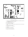
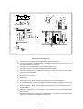
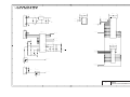
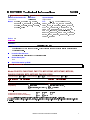
Main PCB Circuit Diagram 1/5
1 FAX engine (ASIC) which integrates a CPU, digital portion of MODEM and gate array
for managing the I/Os, memories, and drivers.
2 XT1, oscillator for the CPU.
3 XT3, oscillator for the calendar clock.
4 XT2, oscillator for the MODEM.
5 Reset IC which turns on at the powering-on sequence and at any of the reset operations.
6 Connector for the control panel
7 Recording head drive voltage detector
8 Inverters
9 Connector for the modular PCB
: Connector for the hook switch PCB
A Backup circuit for the calendar clock
III – 21
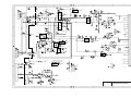
1
2
3
+ 2 6 V
A
# 3
+ 9 V
1
4
5
6
7
8
2
P S
K I A 7 8 0 5
8
4
1
I N
+ 5 V
OUT
GND
+ 5 V
A
+ 5 V
GND
C9 5
C3
C9 6
C9 7
C5
1 6 V 4 7
CC1 0 4
CC1 0 4
1 6 V 4 7
GND
C5 8
CC1 0 4
CC1 0 4
# 8
2
R1 2 0
1
8
GND
4
P 0 V
P 3
B 4 B - P H
+ 9 V
Q1 2
4
V CC
V S S
S CL
A 0
S DA
A 1
T E S T
A 2
6
1 5 D
E P CK
1 5 D
E P DO
3 2
1
R7 6
+ 5 V
RH5 RA 4 7
I N
7
R1 1 9
D. S
MOD E L = *
R7 7
S T D
MOD E L = *
D. S
MOD E L = 0
2 4 L C 1 6 ( 1 8 7 0 MC )
1 K
2 4 L C 3 2 ( 1 9 7 0 MC )
C4
1 6 V 4 7
DA B US
2
GND
GND
P 6
B 2 B - P H
B L A CK
1 6 D
A B US
MOT OR
# 1
3
5
MT D 2 0 0 3 F
4
2
2
7
6
C
8
5
1 3
1
3
5
P 2
6
B 6 B - P H
9
+ 5 V
1 0
1 2
1 9
2 4
R1 1 0
R1 3 0
0
2 0 K
OUT 1
I N1
OUT 2
I N2
OUT 3
I N3
OUT 4
I N4
2 6
MM3
1 7
MM2
1 6
MM4
MB U S
1 6 B
MT I 0
1 2 E
I 0
NC
2 5
MT I 1
1 2 E
NC
NC
NC
NC
NC
I 1
V R
C/ R
1 8
6
1 5 A
RA S
1 5 A
CA S
1 5 B
B A R M WE
R1 1 2
4
1 5 B
B A R MR D
+ 5 B
GND
C9 4
+ 5 B
V CC
R1 1 1
*
2 0
*
# 7
1
1 1
# 5
2 6
1 3
1 5
R2
R1
1 / 2 W
1 / 2 W
1
1
V CC
1 0
A 3
9
A 4
8
A 5
7
A 6
6
A 7
5
A 8
2 7
A 9
2 6
A 1 0
2 3
A 1 1
2 5
DA 3
4
DA 4
2 8
DA 5
2 9
DA 6
3
DA 7
2
DA 8
3 0
A 0
9
A 1
A 2
A 3
B
A 4
A 5
A 6
A 7
A 8
A 9
A 1 0
D0
A 1 1
D1
A 1 2
D2
A 1 3
D3
A 1 4
D4
A 1 5
D5
A 1 6
D6
A 1 7
D7
+ 5 B
1 3
D0
1 4
D1
1 5
D2
1 7
D3
1 8
D4
1 9
D5
2 0
D6
2 1
D7
GND
C6 4
CC1 0 4
( 1 9 7 0 MC )
# 6
( 1 8 7 0 MC )
H M5 1 4 8 0 0 J P
2 6
1 3
V S S
V CC
RS A
2 9
3 0
V CC
V S S
V CC
V S S
C1 0 7
C1
CC1 0 4
CC1 0 4
5 0 v
3 5 V / 2 2 0
- RA S
CC1 0 4
1 0 5
- RA S
2 3
6
- CA S
- CA S
NC
- WE
NC
7
3
2 1
- WE
2 2
2 8
8
4
2 3
- WE
C9 0
D
2 2
2 2
- OE
- OE
- OE
C
P 0 V
*
MT V R
1 5
1
V S S
1 4
4
C1 0 5
P 0 V
Q1 1
1 1
A 2
2 8
- CA S
GND
1 2
A 1
H M5 1 4 4 0 0
3
RS B
- P GM
A 0
CC1 0 4
( 1 9 7 0 MC )
H M5 1 4 4 0 0
2 3
GND
1 6
- OE
1 4
V S A
V S B
2 4
GND
C9 3
CC1 0 4
V MM
GND
- CE
+ 2 6 V
+ 5 V
- RA S
2 3
C1 0 6
CC3 3 2 B
D
R MR D
V P P
V CC
C
NC
V CC
2 1
MM1
NC
V MM
2 2
2 7
1 5 A
2 2
DA 9
1 4 D
C9 1
R OMC
3
# 4
CC1 0 4
1 5 A
3 1
R1 1 3
1
MOD E L = 0
+ 5 B
OUT
GND
B
S T D
2
5
*
DA 1
1 S S 3 7 8
B A T
3
P D2 7 C2 0 0 1 B - 1 5
+ 5 V
4 . 7 k
3
DA 0
9
DA 1
1 0
DA 2
1 1
DA 3
1 2
A 0
DA 4
1 4
DA 5
1 5
DA 6
1 6
DA 7
1 7
DA 8
1 8
DA 9
5
1
D0
DA 0
9
2
D1
DA 1
1 0
2 4
D2
DA 2
1 1
2 5
D3
DA 3
1 2
DQ1
A 1
DQ2
A 2
DQ3
A 3
DQ4
A 4
A 5
A 6
A 7
A 8
A 9
A 0
DA 4
1 4
DA 5
1 5
DA 6
1 6
DA 7
1 7
DA 8
1 8
DA 9
5
1
D4
DA 0
1 0
2
D5
DA 1
1 1
2 4
D6
DA 2
1 2
2 5
D7
DA 3
1 3
DQ1
A 1
DQ2
A 2
DQ3
A 3
DQ4
A 4
A 5
A 6
A 7
A 8
A 9
A 0
DA 4
1 6
DA 5
1 7
DA 6
1 8
DA 7
1 9
DA 8
2 0
DA 9
9
2
D0
3
D1
4
D2
5
D3
DQ1
A 1
DQ2
A 2
DQ3
A 3
DQ4
A 4
DQ5
A 5
DQ6
A 6
DQ7
A 7
DQ8
2 4
D4
2 5
D5
2 6
D6
2 7
D7
A 8
A 9
1 5 D
1 4 D
A
DA B US
E
1 4 E
E
DB A S
P 0 V
S OL
+ 2 6 V
:
1
7
Q2
D3
DT D1 1 3 Z K
1 S S 1 2 0
2
S OL
1 5 D
P 1 3
B 2 B - P H
F
B L UE
F
GND
1
2
3
4
5
6
7
8
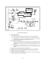
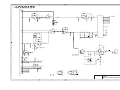
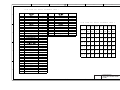
Main PCB Circuit Diagram 2/5
1 Connector for the power supply PCB which supplies 25V and 8V.
2 3-terminal regulator which eliminates unstabilized components of the +8V source to
generate stabilized +5V source.
3 Connector for the Ni-MH battery which supplies approx. 5V.
(Provided on the FAX1570MC/1030/MFC1870MC/1970MC)
4 3-terminal regulator which generates +5B source from +8V to back up the DRAM
(that stores received data).
(Provided on the FAX1570MC/1030/MFC1870MC/1970MC)
5 Connector for the motor
6 Motor driver
7 Connector for the clutch solenoid (that switches the power transmission).
8 E2PROM (32-kilobit for the FAX1570MC/1030/MFC1970MC, 16-kilobit for other models.)
9 ROM (2-megabit. Note that the qualification machines for demonstration have a 4megabit ROM.)
: DRAMs (1-megabyte, two 4-megabit chips) provided on the FAX1570MC/1030/
MFC1970MC.
A DRAM (512-kilobyte) provided on the MFC1870MC. The FAX1170/1270/1010/1020/
MFC1770 has its equivalent DRAM on location #7.
III – 22
1
2
3
4
5
R5 V
CI S
1 -1
1 -2
1 -3
6
7
8
+ 5 V
A
A
1
+ 2 6 V
2
R5 V
R5 V
R9 7
4 7 0
R9 8
2 7 0
3
4
RB
1 2 E
T G
1 2 E
3 -2
R1 2 3
Q8
3 0 0
2 S C3 0 5 2
L I GT
R0 V
1 1 C
R5 V
GND
1 -7
0
1 W
6
R0 V
3 0
C1 0 0
C1 0 2
*
CC1 0 4
# 1 0
4 2
3 8
3 9
7
4 0
4 1
C8
P 9
1 6 V / 1 0
3 7
B 7 B - P H
V I D
K RC1 0 7 S
R1 0 2
1 0 K
R1 0 3
C7
C8 1
1 6 v
CC1 0 4
3 5
V DD
V DD
A T A P
A DRE F L
DGND
DGND
P ORT 0
DGND
P ORT 1
DGND
P ORT 3
A V DD
C1 0 1
S D/ P D7
P D5
P D3
R5 V
3 6
4 6
R0 V
A GND
P D2
A GND
P D1
T RI G
DA CK
I CL K
DRE Q
R1 0 0
P D0
2 . 2 K
Q7
1 2 E
2 S C3 0 5 2
1 2 E
C P WM
R9 9
T G
S MC
1 5 D
1 2 E
2 2 K
E 1 CS
1 5 D S RA M
I ORQ
C8 0
R1 0 1
CC1 0 4
1 -6
1 0 K
2
D
9
R1 0 7
+ 5 V
3 3 K F
CP 3 I
1 2 F
1 0
R1 0 8
1 0 0 K F
1 6 D
2 7
2 3
2 2
2 1
1 4 A
+ 5 V
2 8
MR E Q
WR
RB US
T M
2 9
RD
CK 1 6
1 6 B
R0 V
R0 V
3 1
3 0
RS T L
2 5
3 2
A 0
2 0
A 1
1 9
A 2
1 8
A 3
1 6
A 4
1 5
A 5
1 4
A 6
1 3
A 7
1 2
A 8
1 1
1 0
RS E N
4
3
3 -1
C1 1 2
*
+ 5 V
C1 0 3
CC1 0 2 B
B 5 B - P H
B
B L A CK
5 6
9
1 7
+ 5 V
2 6
C9 8
C9 9
4 9
CC1 0 4
CC1 0 4
6 4
4 -1
I OCS
MT P
4 7
GND
4 8
P H2
R1 2 6
S G- 1 0 5 F 3 0 8
1 0 0 K
RE A R
1 2 D
5 0
5 1
5 2
RDA T
1 2 E
5 3
GND
5 4
C
5 5
5 7
5 8
5 9
GND
+ 5 V
MC S
I OE
ME
S A MP
RD
RS
WR
S H
CL K I N
CL K 1
RE S E T
CL K 2
3 3
4 -2
6 2
6 3
6 1
P H1
R1 2 4
S G- 1 0 5 F 3 0 8
1 0 0 K
F RNT
1 2 D
6 0
A 0
A 1
D0
A 2
D1
A 3
D2
A 4
D3
A 5
D4
A 6
D5
A 7
D6
A 8
D7
8
D0
7
D1
6
D2
5
D3
4
D4
3
D5
2
D6
1
D7
A B US
GND
Q1 3
D
K RC1 0 7 S
1 2 E
DB US
S E ON
1 4 E
4
1 1
R1 0 9
C1 0 9
P 1
C1 0 4
CC1 0 2 B
GND
2 4
P ORT 2
P D4
CC1 0 4
R0 V
2
1 2 D
T E MP
P D6
4 3
R5 V
2 S K 1 3 9 9
C
RS T L
A I N
R0 V
R5 V
Q9
4 4
3 4
1 5 D
V DD
DGND
4 5
1 0
1 K
C L MP
R0 V
RS T H
1 2 E
1 -5
Q1 0
5
F S E N
1
L C8 2 1 0 2 W
R0 V
GND
1
R1 2 8
1 0 0 K
1 2 D
R1 2 1
R3
B
R1 2 9
1 0 0 K
2 0 0
C8 2
CC1 0 4
S E NS OR
+ 2 6 V
R1 2 2
1 -4
Q1
2 S D1 8 5 8
5
2 -1
2 -2
3
+ 5 V
GND
1 0 K F
CC1 0 2
GND
2 -3
2 -4
2 -3
6
8
R1 0 6
1 0 0
R1 0 4
2 0 0
7
2
E
3
6
C8 9
C8 4
C8 8
C8 5
CC1 0 1
CC1 0 1
CC1 0 1
CC1 0 1
S T 2
1 2 D
DOUT
1 2 E
DI N
1 2 E
HDC
1 2 D
S T 1
1 2 D
3 3 F
HRL Y
4 2 E
C ML L
1
P WO N
1 5 D
C ML H
1 5 B
E
4
3
2
# 1 3
U MG5 N
GND
GND
1
2 -5
5
4
L A T C
1 5 C
HRL Y
3 6 E
RI B ON
P 5
C8 3
C8 7
C8 6
R1 0 5
*
*
*
1 0 K
1 2 D
B 1 1 B - P H
F
F
GND
1
2
3
4
5
6
7
8
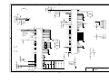
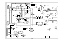
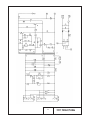
Main PCB Circuit Diagram 3/5
1 Connector for the CIS
1-1:
1-2:
1-3:
1-4
1-5:
1-6:
1-7
Power for the CIS LED array
Clock output
Trigger signal output. One shot of this signal triggers a line of scan.
LED control signal output circuit which controls the intensity of the CIS LED array.
Input of video data (VID) to the FAX engine
Clamp circuitry that gives the bias level to the amplifier of the VID input circuit according to
the CLMP and CPWM signals issued by the CPU (that monitors the current video data
input) for compensating the DC component of video signals for the next scan line.
Working with the FAX engine, this circuitry carries out the standard scanning. (This
circuitry is provided on the FAX1170/1270/1010/1020/MFC1770/1870MC.)
SANYO LSI that carries out the high-quality scanning. (Provided on the FAX1570MC/1030/
MFC1970MC)
2 Connector for the thermal recording head
2-1:
2-2:
2-3:
2-4:
2-5:
Power 5V for the thermal recording head
Thermister signals which are normalized by the resistor network and fed to the FAX engine
Strobe signals
Data signals
Ribbon sensor signal
3 Connector for the sensor PCB
3-1: Paper-edge sensor signal
3-2: Paper ejection sensor signal
4 Document front and rear sensor circuitry that is active only while the SEON signal is on.
4-1:PH2, document rear sensor
4-2:PH1, document front sensor
III – 23
1
2
3
1
A
C2 0
CC6 8 1
R2 3
5 6 K
4
5
6
2 -1
T E L L
4
1 5 C
7
5
R2 6
7 5 K
C2 5
CC2 2 1
R6 5
CNT
R3 1
C2 7
1 0 K
1 3
CC1 0 4
1 5
0
2
CT S L
C
S L
5 3 B
R2 1
1 0 K
# 1 9
1 2
3
D P D MC K
T X OUT
D P D MD T
5
R3 3
4 0 5 3
+ 5 V
+
# 1 8
5 6 K
5 6 K
7
1
1 . 5 K
C4 9
+
+ 2 6 V
K I 3 2 4
R2 2
R3 0
# 1 8
4 . 7 K
I 3 2 4
A P D MC K
CC1 0 2 B
A P D MD T
A RE F
R2 0
1 / 1 0 W
R2 9
6
-
1
1 4
9
A
# 1 5
T C3 5 1 3 3 F
1 0
NCU
8
*
C3
1 K
A RE F
M0 V
M0 V
C4
D8
C5
C2 3
*
*
MU T E
C ML H
1 5 C
M0 V
T A DH
1 1
1 3
RL 2
1 2
1 4
2
0
C
C5 7
R7 1
CC1 0 4
2 7 K
9
A MK
1 0
A MT
1 1
V DD
2
-
C3
1 2
C4
1 3
C5
5
MU T
8
RS T L
1 5
1 4 A
1
B
RX I NA
3
4 0 5 3
5 3 B
1 4 D
CC1 0 4
1 K
# 1 7
1
2 -2
R6 3
1
4 0 5 3
T B US
C4 5
1 5
1
# 1 9
0
- P D
4 3 K
D MT
+ 5 V
CNT
1
C
7
R2 8
D MK
7
1 0
CNT
RL 1
6
B
1 2 C
6
+
C4 7
R7 4
# 1 8
R2 7
R6 2
1 0 0 K
K I 3 2 4
4 . 7 K
1 0 0 K
6
A RE F
CT S L
MOV
C4 4
CC1 0 4
CC2 2 1
1 6
2
D2
C4 6
HZ S 5 C
CC1 0 3 B
C9
RX I NB
V S S
V B I A S
V S S
4
1 4
C4 8
1 6 V 1 0
MOV
CC1 0 4
A RE F
C
5
T L S L
D4
*
R1 3
0
R1 8
0
D5
*
D7
M0 V
1 S S 1 2 0
7
5 1 B , 5 3 B
D6
1 S S 1 2 0
C2 1
CC6 8 1
C
+ 9 V
R2 4
R1 5
1 5 0 K
R2 5
9
1 . 5 K
2 0 0 K
-
T L RL
5 3 A
8
C2 2
1
CC1 0 3 B
1 0
C1 1 1
+
CC1 0 4
R1 6
R1 4
# 1 8
0
4 . 7 K
K I 3 2 4
A RE F
R1 9
R1 7
M0 V
CT RL
*
DA RE C
*
D
1 1 C
T X S L
1 2 C
HA F H
1 1
Q4
Q3
*
K RC1 0 7 S
A RE F
R7 2
1 . 5 K
R7 3
1 . 5 K
1
OT O
R1 2
5
4
3
4 0 5 3
M0 V
1 5 C
M0 V
+ 5 V
C1 1 0
CC1 0 4
1 1
E
GND
1 2
+ 2 6 V
+ 2 6 V
D9
1 S S 1 2 0
R5
1 K
3
P L S
8
1 3
1 5 C
C ML L
RDP S
1
+
8
2
4
R3 5
R1 1 5
C9 2
1 2 K
3 3 K
CC1 0 3 B
R8 9
R3 2
3 . 3 K
1 0 0 K
1 0
1
4 0 5 3
3 -2
: -1
: -2
: -3
1 0 V 1 0 0
5
# 1 9
0
4 0 5 3
1 . 5 K
HF RL
C2
7
-
3
4
5
# 1 7
1
R7 5
5 5 D
RNGO
1 5 B
V OL 1
1 5 E
V OL 2
D
S P
6
2
CC1 0 5 ( 2 1 2 5 CHI P )
C
9
8
1 5 C
C2 8
1
3
CC1 0 4
# 2
N J M3 8 6 M
RNGL
CNT
0
C
3 -1
1 5 C
1 0 0 K
1 4
# 1 7
GND
9
CNT
C
1 2
0
C1 9
1 2 C
9
CNT
1 3
2 -3
5 1 A , 5 3 B
R3 4
P 4
1 K
3 0 0
WH I T E
M0 V
Q5
GND
B 2 B - P H
R3 6
GND
D1 0
:
K RC1 0 7 S
1 S S 1 2 0
R1 3 4
1 K
1 5 C
E
C1 1 3
V OL 3
1 6 V 1 0
( 5 mm)
3 6 E
M0 V
1 5 C
1 2 D
S P ON
GND
+ 5 V
1 4
E A T
1 6
A DL C
1 5 B
1 5 B
1 7
DA S T
1 1 D
1 8
DA S ND
1 1 C
R6
R3 7
R4
2 2 K
2 2 K
1 K
+ 5 V
+ 5 V
2
T L OF
1 5
CI
+ 2 6 v
1 5 C
T L OF 2
4
1 2 D
1 6
1 5 C
F
1 6
# 1 9
C2 6
4 0 5 3
CC1 0 4
4
# 1 7
C5 6
# 1 8
4 0 5 3
CC1 0 4
K I 3 2 4
C2 4
6
CC1 0 3 B
7
8
6
7
8
F
5 0 V
C1 1
C1 2
P 1 0
CC1 0 4
3 5 V 1 0
1 1
I MS A - 9 1 1 0 S - 1 8 L
GND
1
2
GND
M0 V
M0 V
M0 V
3
4
M0 V
5
6
7
8
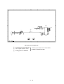
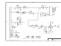
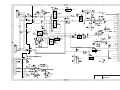
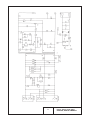
Main PCB Circuit Diagram 4/5
1 Connector for the NCU
2 Analog signal selectors
2-1: Selects either input signals from the handset or those from the MODEM.
2-2: Selects either RL1 or RL2 signals inputted from the communications network.
2-3: Selects either sound signals (e.g., alarm beeps, key clicks and ringer sounds)
generated by the FAX engine or signals selected by 2-2.
3 Voice switching analog selectors
3-1: Switches between the output line and input line for monitoring. When
switched to the output line, this selector allows FAX sending operation to be
monitored; when switched to the input line, it allows received voices to be
monitored.
3-2: Selects either voice signals inputted from the communications network or recorded voice signals inputted from the microphone or handset through the
MODEM.
4 Amplifier circuit for signals outputted from the MODEM.
5 Analog front end IC which processes the analog I/O signals from/to the MODEM.
6 Amplifier & shaper circuit for signals inputted from the communications network.
7 Telephone circuit for transmitting signals.
8 Speaker amplifier circuit which amplifies sounds issued from the above analog signal
selector 2-3 and feeds them to the speaker.
III – 24
9 Connector for the speaker
: Speaker volume control circuit
:-1: VOL1
OFF
ON
ON
:-2: VOL2
OFF
OFF
ON
:-3: VOL3
OFF
OFF
ON
Speaker volume
High
Medium
Low
III – 25
(ON: Closed OFF: Opened)
1
2
3
4
5
6
7
8
A
A
B
B
C
C
3
R5 5
7 5 K
C3 5
CC2 2 1
# 1 6
T C3 5 1 3 3 F
R5 6
R4 8
6
5 6 K
5 6 K
3
-
T X OUT
D P D MC K
7
4 4 D
D
HF RL
D P D MD T
5
C3 6
+
R4 7
4 . 7 K
B A 1 0 3 5 8 F
A P D MC K
CC1 0 2 B
# 1 4
A P D MD T
HRE F
C3
C3 7
2
6 8 1 B
+ 5 V
R5 7
1 0 0 K
R5 3
MI C
R4 3
RL 1
1 0 K
C3 1
R4 4
CC1 0 4
8 . 2 K
HRE F
M0 V
C4
C5
MU T E
- P D
*
5 1 B , 5 3 B
T B US
1 4 D
D
A MK
1 0
A A MD
1 1
C0
1 2
C1
1 3
C2
5
A MU T
8
RS T L
V DD
1 4 A
1
CC1 0 4
1
1 5
RX I NA
3
RL 2
+
R4 6
C3 2
R4 5
CC1 0 4
8 . 2 K
1 0 K
B 2 B - P H
C5 4
# 1 4
R5 8
R6 9
B A 1 0 3 5 8 F
4 . 7 K
1 0 0 K
C5 3
CC1 0 4
CC2 2 1
1 6
C3 3
R5 4
CC6 8 1 B
1 0 0 K
2
RE D
C1 0
MOV
1
A D MD
9
C5 2
2
7
P 1 2
D MK
7
+ 5 V
T L S L
6
E
6
RX I NB
V S S
V B I A S
V S S
C5 5
1 6 V 1 0
E
4
1 4
MOV
CC1 0 4
MOV
HRE F
HRE F
M0 V
+ 5 V
+ 5 V
1 6
F
8
# 1 1
C2 9
# 1 4
4 0 5 3
CC1 0 4
B A 1 0 3 5 8 F
6
7
8
C3 4
1
2
3
F
CC1 0 4
4
M0 V
M0 V
4
5
6
7
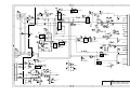
Main PCB Circuit Diagram 5/5
1 Connector for the microphone
2 Voice signal amplifier circuit
3 Analog portion of MODEM
These are provided on the FAX1570MC/
1030/MFC1870MC/1970MC.
III – 26
8
3.3
NCU PCB
The NCU PCB switches the communications line to telephone or built-in MODEM, under the
control of the main PCB.
1
2
3
+ 2 6 V
CR1
MZ F - 2 4 H G
C ML
4
5
6
2
o r
2
A
1 A
OUA Z - S S - 1 2 4 D
NCUS L
4
4
A
S 0 V
5
+
S B T 0 2 6 0 X 2
5
4
3
RA 3 5 1 X 2
3
o r
RL 1
F L 5 R2 0 0 P NX 2
F G
F G
RL 2
P L S
4
1
3
2
4
5
T E L S L
S 0 V
J W1 6
T E L RL
5
8
RE F
S 0 V
4
1
4
V 1
B
3
T E L OF F
RE F
CI
CI
7
A
P L S
RE F
2
3
1
6
5
6
3
4
1
2
4
2
3
+ 5 V
+ 5 V
8
+ 5 V
4
+ 5 V
A
o r
9
S 0 V
B A 1 0 3 5 8
+ 5 V
T E L RL
B
S 0 V
S 0 V
4
+ 2 6 V
C
E
+ 2 6 V
+ 2 6 V
1
T E L OF F
3
C ML
R2 4
J W
4 - 4 P MJ
S 0 V
F G
2
B
RL 2
S 0 V
:
S 0 V
2
C
C
S 0 V
3
J W9
S B T 0 2 6 0 X 4
RE F
S RE F
o r
S RE F
S 0 V
F L 5 R2 0 0 P NX 4
4
T E L S L
1
S 0 V
S 0 V
P 1
A
6 0 3 3 B - 1 2 Z
D
D
3 . C OMP ON E N T S
I N
1
P A RE NT HE S I S
NOT
T O
B E
MOU N T E D .
2
4
3
5
6
NCU PCB Circuit Diagram (U.S.A. versions)
1 Surge absorbers
2 Line relay (CML relay)
3 Line transformer
4 Circuit related to the line transformer
5 High-impedance transformer circuit
6 Calling signal detector
7 Loop current detector
8 Dial pulse generator
9 Telephone circuit
: Reference voltage generation circuit for the operational amplifiers in 4 and 9
A Noise filters (provided on the FAX1570MC/MFC1870MC/1970MC)
III – 27
2
1
2
4
3
5
6
J P 8
( 5 )
1
L I NE
2
CC3 3 3
8
5
0
3
1
2
M
T E L OF F 1
C
L 1 3
CH2
S P 3
M
2
4
C ML
1 0 V
2
J P 2 9
C
T E L OF F 1
S 0 V
( 2 0 )
3 0
( C)
3
Z D1 3
J P 2 8 ( C)
J P 2 1
J P
J P 1 9 ( 2 0 )
6
B
1
RL 1
P L S
6
3
RE F S 0 V
B
DA S T
-
+
2
3
M
C
J P 2 6
A
8
B
J P 2 0 ( 5 )
3 3 2 K
1
9
5
M
C
( 1 0 )
J P 2 7 ( C)
E
B J P 2 2 ( 1 0 )
E
J P 2 5
4
-
+
6
R6 5
RDP S
4
7
C3 7
+
A
( 1 0 )
-
A - OUT
J P 1 1
S
1 7
+ 5 V
( 5 )
RDP S
2
C ML
P L S
+
1
4
3
2 0
RE F
-
E
1 3
E A RT H
K I A 3 2 4 P
1 4
S 0 V
B
1 9
RE F
3
1
6
3
4
RL 2
T E L RL
3
2
6
RDP S
R2 7
J P 9
+ 5 V
A DL C
( 1 0 )
2
5
B
S 0 V
9
S 0 V
DA S ND
4
1
4
2
3
P OL
1 5
C
S 0 V
+ 5 V
+ 5 V
A
T E L RL
CN3
4 - 4 P MJ
S 0 V
J W8
+ 5 V
1 0
S 0 V
1 1
+ 2 6 V
RE F
( 1 0 )
J W1 1
S 0 V
1 2
P 2
I MS A - 6 0 3 3 B
:
S 0 V
( 1 0 )
1 8
S 0 V
7
B I NA T ONE
2
1 6
+ 5 V
S 0 V
C
2
1
1 0 K
A - OUT
+
1
S 0 V
-
4
7
RE F
+ 5 V
T A D
B
+
2
-
J P 1 7 ( 5 )
- 1 8 Z
F G
S 0 V
S 0 V S 0 V
J P 3
J W9
D
+
D
( 1 0 )
( 1 0 )
S 0 V
J W1 0
2
D
( 1 0 )
1
2
G
J P 3 4
DA S ND
S
P 1
S OV
B 2 B - P H
1
2
4
3
5
NCU PCB Circuit Diagram (European versions)
1
Surge absorber
2
Noise filters
3
Line relay (CML relay)
4
Line transformer
5
Circuit related to the line transformer
6
High-impedance transformer circuit
7
Calling signal detector
8
Loop current detector
9
Dial pulse generator & DC current loop circuit
:
Telephone circuit
a
Reference voltage generation circuit for the operational amplifier in 5.
b
Line current detection input circuit
III – 28
6
3.4
Control Panel PCB
The control panel PCB and the main PCB communicate with each other by serially transmitting commands and data.
The control panel unit consists of a gate array, an LCD and LEDs (not provided on the
FAX1170/1270/1010/1020/MFC1770), which are controlled by the gate array according to
commands issued from the FAX engine on the main PCB.
The calendar clock is backed up by the backup circuit on the main PCB.
The panel FPC is a flexible keyboard PCB which integrates the key matrix having rubber
keytops.
Main PCB
Control Panel PCB
SIDN
Serial
Communications
Ports
SDOUT
PCLK
LCD
Gate Array
FAX
Engine
I/O Ports
+5V
Panel FPC
(Key Matrix)
POWER
+5V
RESET
Backup
Circuit
Reset
Circuit
RESET
LEDS
(Not provided on the
FAX1170/1270/1010/
1020/MFC1770)
Control Panel PCB and its Related Circuit
III – 29
3.5
Power Supply PCB
The power supply uses the switching regulation system to generate DC power (+25V and
+8V) from a commercial AC power supply.
The +25V source is stabilized and fed to the motor and solenoid for feeding documents and
recording paper, the main PCB, and also fed to the CIS LED array.
The +8V source is not stabilized and fed to the speaker. It is also fed to the main PCB where
the 3-terminal regulator eliminates unstabilized components of the +8V source to generate
stabilized +5V source. The +5V source is fed to the logic, control panel, recording head, and
sensors.
Fuse
Commercial
AC Power Line
Lightning
Surge
Absorption
Circuit
Link
Filter
Rectifier
Circuit
Main PCB
Output Feedback
Oscillator
Circuit
25 V
Output
Circuit
25 V
8V
Output
Circuit
8V
Power Supply Circuit
III – 30
CHAPTER IV.
DISASSEMBLY/REASSEMBLY
AND LUBRICATION
CONTENTS
1.
DISASSEMBLY/REASSEMBLY ....................................................................
IV-1
■ Safety Precautions ....................................................................................
IV-1
Tightening Torque List ............................................................................
IV-2
■ Preparation ................................................................................................ IV-3
■ How to Access the Object Component ......................................................
IV-3
■ Disassembly Order Flow ...........................................................................
IV-4
1.1
Recording Head ASSY ..........................................................................
IV-5
1.2
Recording Paper Cover ASSY ..............................................................
IV-8
1.3
Platen ..................................................................................................... IV-9
1.4
Lock Levers and Their Shaft .................................................................
1.5
Chute ASSY ........................................................................................... IV-11
1.6
Paper Feed Roller ASSY and Paper Feed Sub Chute ..........................
IV-12
1.7
Paper Feed Chute, Sensor PCB, and Paper-edge
and Paper Ejection Sensor Actuators ...................................................
IV-15
1.8
Paper Ejection Roller ............................................................................
IV-17
1.9
Gears on the Platen Frame ...................................................................
IV-18
1.10 Control Panel ASSY ..............................................................................
IV-19
1.11 Panel Rear Cover and Control Panel ....................................................
IV-21
IV-10
1.12 Inner Cover ............................................................................................ IV-23
1.13 White Pressure Roller and CIS Unit ......................................................
IV-24
1.14 Handset Mount ....................................................................................... IV-26
1.15 Side Covers R and L .............................................................................
IV-27
1.16 Speaker and Battery .............................................................................
IV-29
1.17 Document Front Sensor Actuator ..........................................................
IV-30
1.18 Main Frame ............................................................................................ IV-31
1.19 Separation Roller, its Support, and Document Rear Sensor Actuator ...
IV-33
1.20 Document Ejection Roller and CIS Leaf Spring ....................................
IV-35
1.21 Motor ...................................................................................................... IV-36
1.22 Solenoid ................................................................................................. IV-37
1.23 Drive Gears ............................................................................................ IV-38
1.24 Friction Torque Transmission ASSY, its Related Gears,
and Slip Gear 40 ...................................................................................
IV-39
1.25 Ribbon Bushings ...................................................................................
IV-40
1.26 Bottom Plate .......................................................................................... IV-40
2.
1.27 Main PCB, NCU PCB and Modular PCB ..............................................
IV-41
1.28 Power Supply PCB ...............................................................................
IV-43
1.29 Harness Routing ...................................................................................
IV-45
LUBRICATION ................................................................................................ IV-46
1. DISASSEMBLY/REASSEMBLY
■ Safety Precautions
To prevent the creation of secondary problems by mishandling, observe the following precautions during maintenance work.
(1)
Always turn off the power before replacing parts or units. When having access to the
power supply, be sure to unplug the power cord from the power outlet.
(2)
Be careful not to lose screws, washers, or other parts removed for parts replacement.
(3)
When using soldering irons and other heat-generating tools, take care not to damage
the resin parts such as wires, PCBs, and covers.
(4)
Before handling the PCBs, touch a metal portion of the equipment to discharge static
electricity; otherwise, the electronic parts may be damaged due to the electricity
charged in your body.
(5)
When transporting PCBs, be sure to wrap them in conductive sheets such as aluminum
foil.
(6)
Be sure to reinsert self-tapping screws correctly, if removed.
(7)
Tighten screws to the torque values listed on the next page.
(8)
When connecting or disconnecting cable connectors, hold the connector bodies not the
cables. If the connector has a lock, always slide the connector lock to unlock it.
(9)
Before reassembly, apply the specified lubricant to the specified points. (Refer to Section 2 in this chapter.)
(10)
After repairs, check not only the repaired portion but also that the connectors and other
related portions function properly before operation checks.
IV – 1
Tightening Torque List
Location
Screw type
Q'ty
Tightening torque (kgf•cm)
Recording head ASSY
Screw, cup S 3x6
2
7 ±2
Recording paper cover ASSY
Taptite, cup S 3x8
2
7 ±2
Chute ASSY
Taptite, cup S 3x8
2
5 ±2
Paper feed chute
Taptite, cup S 3x8
2
5 ±2
Panel rear cover
Taptite, cup B 3x8
4
4 ±2
Inner cover
Taptite, cup S 3x8
4
5 ±2
CIS holders R and L
Taptite, cup B 3x8
2
4 ±1
Handset mount
Taptite, cup B 3x8
2
5 ±2
Bottom plate (main frame)
Screw, cup S 3x6
2
7 ±2
Main frame
Taptite, cup B 3x8
4
5 ±2
Motor
Screw, pan (washer) 3x6DB
1
7 ±2
Friction holder
Screw, cup S 3x6
1
7 ±2
Taptite, cup B 3x8
6
5 ±2
(Friction torque transmission ASSY)
Bottom plate
IV – 2
■ Preparation
Prior to proceeding to the disassembly procedure,
(1)
Unplug
- the modular jack of the telephone line,
- the modular jack of the curled cord (and remove the handset),
- the BT modular jack adapter if mounted, and
- the modular jack of an external telephone set if mounted. (Not shown below.)
(2)
Remove
- the paper wire extension,
- the paper support,
- the document support,
- the document ejection tray, and
- the ribbon cartridge.
Document support
Ribbon cartridge
Paper support
Handset and
curled cord*
Paper wire
extension
Telephone
line cord
BT modular jack
adapter
(provided on the
New Zealand
version)
Document
ejection tray
(* Not provided on the FAX1010)
■ How to Access the Object Component
•
On the next page is a disassembly order flow which helps you access the object component. To remove the separation roller, for example, first find it on the flow and learn its
number (I in this case). You need to remove parts numbered 1, :, B, C, D, E, F,
G, and H so as to access the separation roller.
•
Unless otherwise specified, the disassembled parts or components should be reassembled in the reverse order of removal.
IV – 3
IV – 4
15
13
12
19
23
22
21
Drive gears
Solenoid
Motor
25
24
20
19 Separation roller and
its support
Main frame
Side cover R
Document rear sensor
actuator
18
Side cover L
15
Inner cover
Panel rear cover
- ADF parts
- Pressure rollers
- Anti-static brush
Control panel
- Control panel PCB
- FPC key
- LCD
- Microphone *5
Control panel
ASSY
2
Handset mount* *
Side cover **
11
10
ROM cover
* For models except the FAX1010
**For the FAX1010
CIS unit
14
1
Recording head *
ASSY
13 White pressure
roller
1
1
16
16
Ribbon bushings
5
4
7
8
6
4
Main PCB, NCU *
PCB and modular
PCB
Platen frame
28 Power supply
PCB
Paper feed sub chute
Paper feed roller
ASSY
26
Bottom
plate
*5 Provided on the FAX1570MC/1030/MFC1870MC/1970MC.
On the modular PCB is the cover sensor.
*4 On the main PCB are the document front and rear sensors.
sensor.
*1 On the recording head are the ribbon sensor and its actuator.
*2 On the hook switch PCB is the hook switch sensor.
*3 On the sensor PCB are the paper-edge sensor and paper ejection
27
6
Separation pad ASSY
Paper ejection roller
7
Paper feed chute
Chute ASSY
Lock levers and
their shaft
Recording paper
cover ASSY
*3
- Sensor PCB
- Paper-edge sensor
actuator
- Paper ejection
sensor actuator
Document front
sensor actuator
7
Platen
Document ejection
roller
17
*5
3
Friction torque transmission ASSY,
related gears and slip gear 40
20
Battery
Speaker
Gears on
the platen
frame
CIS leaf spring
9
2
■ Disassembly Order Flow
1.1
Recording Head ASSY
(1)
Push the open button and fully open the recording paper cover ASSY.
Open button
Recording paper
cover ASSY
(2)
As shown below, insert the tip of a flat screwdriver into the square hole and release the
hook "x" of the ROM cover, lift up the ROM cover slightly, and then release the hook "y"
to take out the ROM cover.
ROM
cover
ROM cover
Flat
screwdriver
Flat
screwdriver
Hook "X"
Hook "Y"
IV – 5
(3)
Remove the two screws from the recording head ASSY.
(4)
Disconnect the relay connector of the head-power harness.
NOTE: To disconnect the relay connector, push the lock of the relay connector to release.
(5)
Disconnect the main-head harness from the main PCB.
(6)
Lift up the recording head ASSY.
Lock of relay connector
Head-power
harness
Recording head ASSY
Main-head
harness
Head-power
harness
FAX1170/1270/1010/1020/MFC1770
FAX1570MC/1030/MFC1870MC/1970MC
Main-head
harness
(NCU connector)
(NCU
connector)
P9
P1
P5
P7
P14
P2
P12
P10
P1
P15
P4
P3
P6
P11
(Modular
PCB
connector)
P5
P10
P11
P3
P13
P2
P8
Main-head harness
(Modular
PCB
connector)
Main PCB
P4
P9
Main PCB
P12
(Front)
(Front)
IV – 6
(7)
To disassemble the recording head ASSY, follow the steps below.
1) Remove the head protection plate by unhooking the two latches.
2) Turn the recording head ASSY upside down and release the head-power harness
from the adhesive tape.
3) Place the recording head ASSY rightside up.
4) Push down both ends of the recording head and move it to the rear to release the
tabs from the cutouts provided in the recorder frame as shown below.
NOTE: Take care not to lose the three springs placed under the recording head.
Head protection plate
Latches
Recording
head
Ribbon sensor
and actuator
Tab
Tab
Main-head
harness
Head-power harness
Head springs
Recorder
frame
Head
spring
Bring the spring
end into contact
with the edge of the
cutout.
■ Reassembling Notes
•
When reinstalling the recording head, make sure that the three head springs are set into
place; that is, each spring end is in contact with the edge of the cutout as illustrated
above.
•
Be sure to tape the head-power harness onto the bottom of the recorder frame.
•
When reinstalling the recording head ASSY, put the two harnesses under the center
beam of the main frame as shown in Section 1.29.
•
After installation, check the routing of the main-head harness and head-power harness,
referring to Section 1.29.
IV – 7
1.2
Recording Paper Cover ASSY
(1)
Pull the paper front cover towards you.
(2)
To remove the A4 paper guides, insert the tip of a flat screwdriver as shown below and
twist it to release two latches of each paper guide from the recording paper cover.
NOTE: Once removed, those paper guides will become unusable and new parts will
have to be put back in.
(3)
Remove the two screws.
(4)
Push the open button and open the recording paper cover ASSY.
Paper guides
Recording paper
cover ASSY
Paper front cover
Open button
Paper guide
(5)
Lift up the rear of the recording paper cover ASSY and take it out to the front.
Recording paper cover ASSY
1
2
Recess
Platen frame's tab
■ Reassembling Notes
•
When reinstalling the recording paper cover ASSY, first fit the recesses provided on the
right and left insides of the recording paper cover ASSY over the tabs of the platen frame,
and then put the rear of the recording paper cover ASSY into place.
IV – 8
1.3
Platen
(1)
At the left end of the platen, remove the platen gear (Gear 23) by pulling its pawl outwards and then remove the bushing.
(2)
At the right end, remove the gear 33RB by pulling its pawl outwards and then remove
the bushing.
(3)
Move the platen to the left to take out the right end from the platen frame and then take
it out to the right.
Bushing
Gear 33RB
Platen
Platen frame
Bushing
Platen gear
(Gear 23)
Left end
Right end
Long
Short
■ Reassembling Notes
•
Reinstall the platen with its longer shaft end facing to the left.
•
Take care not to sandwich the black sub chute film between the platen and the paper feed
sub chute.
IV – 9
1.4
Lock Levers and Their Shaft
(1)
At each end of the lock lever shaft, release the lock spring from the lock lever and the
platen frame.
(2)
Turn the lock lever R clockwise (when viewed from the right side) and pull it out from
the shaft. Then, the lock lever L, lock springs, and lock lever shaft also come off.
Lock spring R
2
3
Lock lever R
1
Platen frame
Lock lever R
Lock spring R
Lock lever shaft
Lock lever L
Lock spring L
IV – 10
1.5
Chute ASSY
(1)
Remove the two screws.
(2)
Move the chute ASSY to the left to release tab "a" from the platen frame, pull the chute
ASSY towards you, and take it out.
Chute ASSY
Platen
frame
Tab "a"
Tab "b"
Chute ASSY
Tab "a"
Tab "b"
Tab "b"
Cutout
■ Reassembling Notes
•
First fit tabs "b" provided on the chute ASSY into the cutouts in the platen frame, turn the
chute ASSY to the rear, and then move it to the right.
IV – 11
1.6
Paper Feed Roller ASSY and Paper Feed Sub Chute
(1)
Remove the front cover sensing actuator from the paper feed roller shaft by pulling up
the actuator's rear edge as shown below.
Front cover sensing
actuator
Paper feed roller ASSY
(Front)
Pull up here
to remove.
Platen frame
Front cover sensing
actuator
Boss of the paperedge sensor actuator
(2)
At the left end of the paper feed roller ASSY (when viewed from the rear), remove the
bushing by pulling its pawls outwards.
(3)
At the right end, remove the paper feed roller gear (Gear 55) by pulling its pawl outwards.
Next, pull the paper feed roller shaft to the right until the left end of the shaft comes out
of the main frame and then tilt the shaft to the right so that the bushing-fixed end can
pass through the lower hole, and take it out to the left.
Bushing
Paper feed roller ASSY
Paper feed roller
gear (Gear 55)
Lower hole
Pawled bushing
(Rear)
IV – 12
(4)
At the either end of the paper feed sub chute, release the latch from the paper feed
chute with a flat screwdriver as illustrated below, and then pull up the paper feed sub
chute.
Paper feed sub chute
Sub chute
film
Slot provided
in the paper
feed chute
Latch
Paper feed
chute
Latch
Platen frame
(Rear)
Latch
Leading-edge sensor
actuator
■ Reassembling Notes
•
When setting the paper feed sub chute, push the paper-edge sensor actuator into the
home position.
•
Set the paper feed sub chute so that the sub chute film comes into the slot provided in the
paper feed chute.
IV – 13
•
When setting the paper feed roller ASSY at the left side of the platen frame, turn up the
planet gear 34 of the arm P ASSY so that the planet gear 34 comes above the sun gear
39/24 and becomes engaged with the paper feed roller gear (Gear 55), as illustrated below.
Clutch gear ASSY
Gears 18/41
Platen frame
Planet gear 34
Sun gear 39/24
Paper feed
roller gear
(Gear 55)
•
When setting the front cover sensing actuator onto the paper feed roller shaft, make sure
that it supports the boss of the paper-edge sensor actuator as shown on the previous
page.
IV – 14
1.7
Paper Feed Chute, Sensor PCB, and Paper-edge and Paper Ejection Sensor
Actuators
(1)
Remove the two screws.
(2)
Remove the sensor PCB by releasing the two latches.
(3)
Disconnect the main-sensor harness from the sensor PCB.
(4)
Pull up the lead wires of the main-sensor harness out of the sheath, and then take out
those wires (not the sheathed section) from the clamp of the paper feed chute.
(5)
Take out the paper feed chute.
Pull up the
lead wires
out of the
sheath.
Main-sensor harness
Paper feed chute
Platen
frame
Sensor PCB
(Rear)
Clamp (on the
paper feed chute)
Platen frame
Main-sensor
harness
IV – 15
(6)
Remove the paper-edge sensor actuator by pulling the support "x" outwards.
(7)
Remove the paper ejection sensor actuator by pushing the hook "y" from the rear of the
paper feed chute.
Paper ejection sensor actuator
Paper ejection sensor (PH1)
Paper-edge sensor (PH2)
Latch
Latch
Paper ejection sensor
actuator
Paper-edge sensor
actuator
Sensor
PCB
Hook "y"
Support "x"
Separator pad
(Rear)
Spring
Paper feed
chute
Sensor PCB
Paper ejection sensor (PH1)
Paper-edge sensor (PH2)
Main-sensor harness connector
(Rear)
(8)
Pull up the separator pad while squeezing it to the right or left. The spring also comes
off.
■ Reassembling Notes
•
Make sure that the paper ejection sensor actuator is set on the sensor PCB.
•
As illustrated on the previous page, route the main-sensor harness through the cutout of
the platen frame. When routing it through the clamp of the paper feed chute, first put the
lead wires only into the clamp and then pull up the vinyl sheath.
IV – 16
1.8
Paper Ejection Roller
(1)
At the left end of the paper ejection roller (when viewed from the rear), remove the
bushing by pulling its pawls outwards.
(2)
At the right end, remove the paper ejection roller gear (Gear 40) by pulling its pawl outwards. Next, take out the paper ejection roller together with the bushing and the curved
washer.
Paper ejection roller
Curved washer
Bushing
Paper ejection
roller gear
(Gear 40)
Pawled
bushing
Platen
frame
(Rear)
IV – 17
1.9
Gears on the Platen Frame
Paper ejection roller gear
(Gear 40)
Gears 18/41
Platen frame
Clutch gear ASSY
Paper feed roller gear
Planet gear 34 of
the arm P ASSY
Sun gear 39/24
W (Clutch
gear ASSY)
(Gears 18/41)
X (Paper ejection roller
gear, Gear 40)
V
U
T (Paper feed roller gear, Gear 55)
Platen frame
S (Planet gear
34 of Arm P
ASSY)
R (Sun gear
39/24)
IV – 18
a (Platen gear,
Gear 23)
1.10 Control Panel ASSY
(1)
Remove the ROM cover, referring to Section 1.1, steps (1) and (2).
(2)
Disconnect the main-panel harness and the main-mike harness (for the FAX1570MC/
1030/MFC1870MC/1970MC) from the main PCB.
(3)
Slightly open the control panel ASSY as shown below.
(4)
Push the right and left arms of the control panel ASSY outwards with your thumbs to
unhook them from the bosses provided on the inner cover, then slide the control panel
ASSY to the rear.
Main-panel harness
Main-mike harness (for the FAX1570MC/1030/
MFC1870MC/1970MC)
Main-panel harness
Main-mike harness (for the FAX1570MC/
1030/MFC1870MC/1970MC)
Control panel
ASSY
Arm of the control
panel ASSY
Boss provided on the
inner cover
IV – 19
FAX1570MC/1030/MFC1870MC/1970MC
FAX1170/1270/1010/1020/MFC1770
Main-panel
harness
(NCU
connector)
(NCU connector)
Main-panel
harness
P5
P10
P1
P11
P3
P13
P2
P8
Main-mike
harness
P9
P5
P14
P7
P12
P1
P15
P4
P2
P10
(Modular PCB
connector)
P3
P11
P6
(Modular
PCB
connector)
P4
P9
Main PCB
Main PCB
P12
(Front)
(Front)
■ Reassembling Notes
•
After installation, check the routing of the main-panel harness and the main-mike harness
(only for the FAX1570MC/1030/MFC1870MC/1970MC), referring to Section 1.29.
IV – 20
1.11 Panel Rear Cover and Control Panel
(1)
Place the control panel ASSY upside down.
(2)
Remove the ADF parts, the pressure rollers and anti-static brush from the panel rear
cover. Once removed, the ADF parts will become unusable and new parts should have
to be put back in.
(3)
Remove the four screws from the panel rear cover.
(4)
Insert the tip of a flat screwdriver between the front edge of the panel rear cover and
the control panel, then unhook the panel rear cover from the eight "X" latches provided
on the control panel. Lift up the panel rear cover.
(5)
To disconnect the main-panel harness from the control panel PCB, take off the rubber
foot. Once removed, the rubber foot will become unusable and new parts should have
to be put back in.
(6)
To take out the control panel PCB and the FPC key, unhook the PCB from the two
latches ("Y" on the FAX1170/1270/1010/1020/MFC1770, "Z" on the FAX1570MC/1030/
MFC1870MC/1970MC) on the control panel. Unlock the LCD cable connector and disconnect the LCD flat cable.
(7)
To separate the FPC key from the control panel PCB, unlock the FPC key connector
and disconnect the FPC key.
Spring plate A
Separation rubber
Anti-static brush
ADF parts
Spring plate B
Pressure roller, front
Pressure roller, rear
Panel rear cover
FPC key
Main-panel harness
Control panel PCB
(FAX1170/1270/1010/1020/MFC1770)
Rubber foot
FPC key connector
Control panel PCB
(FAX1570MC/1030/MFC1870MC/
1970MC)
LCD cable connector
Microphone
(Provided on the FAX1570MC/
1030/MFC1870MC/1970MC)
8 "X" latches
"Z"
(Rear)
Control panel
(placed upside down)
"Z"
LCD
2 "Y" latches
IV – 21
(8)
To take out the LCD, remove the control panel PCB and the FPC key in step (6). As
shown below, insert the tip of a flat screwdriver under clamp "D" in the direction of arrow
F and push up clamp "D" slightly to release the LCD from clamp "C." In the same way,
insert the screwdriver under clamp "A" to release the LCD from clamp "B."
Then push out the LCD with your fingers in the direction of arrow R.
F
"A"
Flat screwdriver
R
LCD
"B"
(Rear)
F
"C"
R
"D"
■ Reassembling Notes
•
To put the LCD back into place, insert the tip of a flat screwdriver under clamp "D" (see
the above illustration) in the direction of arrow R, push up clamp "D" slightly, and then put
the right edge of the LCD under clamp "D." In the same way, insert the screwdriver under
clamp "A" to put the left edge of the LCD under clamp "A."
Then push the LCD into place with your fingers in the direction of arrow F.
•
When handling the LCD, take care not to scratch or damage the panel sheet. Replace it
if scratched or damaged.
•
A new LCD is covered with a protection sheet. Before installing it, remove the protection
sheet.
•
After connecting the main-panel harness to the control panel PCB, be sure to attach a
new rubber foot on the top of the connector as shown below.
The edge of the rubber foot should not protrude
from this edge of the connector housing.
(Top view)
Rubber foot
Align this edge of a rubber foot
with the edge of the connector
housing.
Rubber foot
Should be flush.
(Side view)
•
When setting the panel rear cover onto the control panel, pass the main-panel harness
and main-mike harness (provided on the FAX1570MC/1030/MFC1870MC/1970MC)
through the cutout provided in the panel rear cover.
IV – 22
1.12 Inner Cover
(1)
Remove the four screws.
(2)
While lifting up the inner cover, release the five latches with the tip of a flat screwdriver.
5 latches
Inner cover
IV – 23
1.13 White Pressure Roller and CIS Unit
(1)
Swing the tabs of the bushings R and L towards you to the release position, and then
lift them up together with the white pressure roller and its gear.
To remove the bushing L, take off the white pressure gear by pulling its pawl outwards.
White pressure roller
Bushing R
White pressure roller gear
Bushing L
Pull here towards you.
(2)
Disconnect the CIS harness from the main PCB.
FAX1170/1270/1010/1020/MFC1770
FAX1570MC/1030/MFC1870MC/1970MC
(NCU
connector)
(NCU connector)
P5
P1
P7
P2
P14
P12
P1
P15
P4
P5
P10
P11
P9
P13
P2
P8
P3
P10
(Modular PCB
connector)
P3
P11
P6
(Modular
PCB
connector)
Main PCB
P4
P9
Main PCB
P12
(Front)
(Front)
CIS harness
CIS harness
IV – 24
(3)
Tilt the CIS unit towards you to release the rear latches from the main frame, and the
CIS unit comes off.
Rear latch
CIS holder
Front latch
CIS harness
CIS unit
Leaf spring
(4)
Remove the CIS holders R and L as shown below.
CIS holder, R
CIS holder, L
CIS unit
CIS harness
■ Reassembling Notes
•
When reinstalling the CIS unit, pass the CIS harness through the cutout provided in the
main frame.
First, hook the front latches of the CIS holders in the main frame while pressing the CIS
unit against the leaf spring and then hook the rear latches.
IV – 25
1.14 Handset Mount (for models except the FAX1010)
Side Cover (for the FAX1010)
(1)
Disconnect the hook switch harness* from the main PCB.
(2)
Remove the two screws from the handset mount* or the side cover**.
(3)
Twist the handset mount* or the side cover** so that it tilts over to the left and its upper
end works out of the bosses provided on the side cover L.
(FAX1010)
(Models except the
FAX1010)
Side cover L
Side
cover**
Thick portions "T" whose outer face
should be flush with the outer face of
the side cover L.
Handset mount*
* For models except the
FAX1010
Handset mount*
** For the FAX1010
(4)
To disassemble the handset mount* for models except the FAX1010, unhook the two
latches with a flat screwdriver.
Upper mount
Latch
Latch
Hook switch PCB
Through the cutout
Hook switch harness
Lower mount
Routing of the hook
Underneath the switch harness
hook switch
PCB
■ Reassembling Notes
•
When assembling upper and lower mounts, route the hook switch harness underneath
the hook switch PCB and through the cutout as shown above. Take care not to pinch the
harness between the upper and lower mounts.
•
The front and rear upper edges "T" of the handset mount are thick. Be sure to make their
outer face flush with the outer face of the side cover L.
IV – 26
1.15 Side Covers R and L
(1)
Lift up the front of the side cover R and take it out.
(2)
Disconnect the main-sensor harness from the main PCB, and then lift up the front of the
side cover L and take it out together with the main-sensor harness.
Platen frame
Side
cover L
Routing of the mainsensor harness
Side
cover R
Hole
Hole
Tab
■ Reassembling Notes
•
Before putting back the side cover L, route the main-sensor harness as illustrated above.
•
When setting the side covers, put each rear edge under the tab and fit each hole over the
boss provided on the main cover.
•
After installation, check the routing of the main-sensor harness, referring to Section 1.29.
IV – 27
FAX1170/1270/1010/1020/MFC1770
FAX1570MC/1030/MFC1870MC/1970MC
(NCU connector)
(NCU connector)
P9
P5
P7
P5
P10
Mainsensor
harness
P1
P11
P14
P2
P12
P1
P15
P4
Mainsensor
harness
P13
P2
P8
P3
P10
(Modular
PCB
connector)
P3
P11
P6
(Modular
PCB
connector)
Main PCB
P4
Main PCB
P9
P12
(Front)
(Front)
IV – 28
1.16 Speaker and Battery
(1)
Disconnect the speaker harness from the main PCB, and pull up the speaker.
(2)
For the FAX1570MC/1030/MFC1870MC/1970MC, disconnect the battery harness from
the main PCB and pull up the battery.
Speaker
Document
front sensor
actuator
Speaker harness
Battery
Battery harness
FAX1170/1270/1010/1020/MFC1770
(Provided on the FAX1570MC/1030/
MFC1870MC/1970MC)
FAX1570MC/1030/MFC1870MC/1970MC
(NCU connector)
(NCU connector)
P5
P10
P1
P11
P13
P2
P8
P3
P9
P5
P14
P7
P12
P10
P1
P15
P4
P2
P3
P6
P11
(Modular
PCB
connector)
P4
Speaker (Modular
harness PCB
connector)
Speaker
harness
P9
Main PCB
Main PCB
Battery
harness
P12
(Front)
(Front)
■ Reassembling Notes
•
Route the speaker harness and the battery harness through the hole provided in the main
frame and through the groove on the main cover, and then hook them on the T-shaped
boss (refer to Section 1.29).
If either of these harnesses is loose, it will interfere with the document front sensor actuator, resulting a sensing error.
IV – 29
1.17 Document Front Sensor Actuator
(1)
As shown below, push down the latch of the right end of the document front sensor actuator to release it from the hole provided in the main frame, move it to the left, and
then lift it up.
Document front
sensor actuator
Push here.
IV – 30
1.18 Main Frame
(1)
Place the machine upright as shown below.
(2)
Remove two screws "a" from the bottom plate.
Equipment placed
upright
Bottom plate
"a"
"a"
(3)
Place the machine rightside up.
(4)
Disconnect the following four harnesses from the main PCB:
• Solenoid harness (2-pin)
• Motor harness (6-pin)
• Power-main harness (4-pin)
• Main-head harness (11-pin)
NOTE: Unhook the motor harness and its ferrite core from the bosses provided on the
main cover.
(5)
Disconnect the relay connector of the head-power harness.
NOTE: To disconnect the relay connector, push the lock of the relay connector to release.
FAX1170/1270/1010/1020/MFC1770
Ferrite core
Head-power harness (Relay
connector)
Power-main harness
Main-head harness
T-shaped boss
Motor harness
Solenoid harness
Motor
Main PCB
(Front)
IV – 31
FAX1570MC/1030/MFC1870MC/1970MC
Ferrite core
Head-power harness (Relay
connector)
Power-main harness
Main-head harness
T-shaped boss
Motor harness
Solenoid
harness
Motor
Main PCB
(Front)
(6)
Remove four screws "b" and lift up the main frame.
"b"
Main frame
Main cover
■ Reassembling Notes
•
Route the motor harness and hook its ferrite core on the main frame as illustrated on the
previous page or this page.
•
Be sure to secure the main frame with two screws "a" which were removed in step (2).
IV – 32
1.19 Separation Roller, its Support, and Document Rear Sensor Actuator
(1)
At the left side of the main frame, remove the spring and pull out the clutch lever by
pulling its pawl outwards.
(2)
Remove the gear 20/40, and then remove the gear 33 by pulling its pawl outwards.
(3)
Pull the latch towards you and pull out the separation roller gear to the left, and the
separation roller comes off.
Separation roller
Main frame
Gear 33
Latch
Separation
roller gear
Clutch lever
Spring
(4)
Gear 20/40
As shown below, release the latch with the tip of a flat screwdriver and slide the separation roller support to the right and lift it up.
Latch
Separation roller support
IV – 33
(5)
To remove the document rear sensor actuator, push down the latch of its right end to
release it from the hole provided in the main frame, move it to the left, and then take it
out.
Document rear sensor actuator
Push here.
IV – 34
1.20 Document Ejection Roller and CIS Leaf Spring
(1)
To remove the document ejection roller, pull out the gear 14/20 by pulling its pawl outwards. Next, move the document ejection roller to the left and take it out downwards.
Gear 14/20
Document ejection roller
(2)
To remove the CIS leaf spring, pull up its lower end with the tip of a flat screwdriver and
move it in the direction of the arrow shown below.
CIS leaf spring
Flat screwdriver
IV – 35
1.21 Motor
(1)
To remove the motor, at the left side of the main frame, unhook the spring and then pull
out the clutch lever by pulling its pawl outwards. Next, remove the screw and turn the
motor clockwise when viewed from the left.
Motor
Clutch lever and spring
IV – 36
1.22 Solenoid
(1)
At the left side of the main frame, remove the spring and pull out the clutch lever by
pulling its pawl outwards.
(2)
Remove the gear 20/40.
(3)
Remove the arm B ASSY and arm A ASSY by pulling the arm B's pawl outwards.
(4)
Push up the clamp and remove the solenoid.
Solenoid
Arm A ASSY
Arm B ASSY
Clamp
Clutch lever
Solenoid
and spring
Gear 20/40
IV – 37
1.23 Drive Gears
(1)
At the left side of the main frame, remove the clutch lever, gears, and arm ASSYs, by
pulling their pawls outwards (if any).
Main
frame
Gear 33
Gear 18
Gear 33/45
Gear 39
Cover sensor actuator
Actuator spring
Arm C ASSY
(Planet gear 44)
Sun gear 36/27
Arm B ASSY
(Planet gear 20B)
Arm A ASSY
(Planet gear 20A)
Sun gear 20/90
Gear 39
Clutch lever
Gear 20/40
Gears 14/20
■ Reassembling Notes
•
If you have disassembled the above gear train, reassemble it referring to the illustration
below.
C (Planet gear 20B of Arm B ASSY)
M (Gear 39)
Z (Gear 33/45)
D (Gear 33)
F (Separation roller gear)
Q (Gear 33)
I (White pressure
roller gear)
(Front)
O (Gear 39)
P (Gear 18)
Main frame
Y (Planet gear 44
of Arm C ASSY)
N (Sun gear
36/27)
K (Document
ejection roller
gear)
E (Gear 20/40)
G H J
Clutch lever
A (Motor gear)
(Gears 14/20)
L (Planet gear 20A of Arm A ASSY)
B (Sun gear 20/90)
IV – 38
1.24 Friction Torque Transmission ASSY, its Related Gears, and Slip Gear 40
(1)
At the right side of the main frame, remove the ribbon drive gear (Gear 24) by pulling its
two pawls outwards.
(2)
Remove the screw and take off the friction holder.
(3)
Remove the gear 18 by pulling its pawl outwards and then take off the gear 20/24 and
the friction torque transmission ASSY (Gear 46).
Ribbon drive gear (Gear 24)
Gear 20/40
Gear 18
Friction torque transmission
ASSY (Gear 46)
Friction holder
Right side of the main frame
(4)
At the inside of the right rear side of the main frame, remove the retaining ring E3 and
then take out the slip gear 40, friction pad, and back tension spring.
(Rear)
Right side of the
main frame
Back tension spring
Retaining ring E3
Slip gear 40
IV – 39
Friction pad
1.25 Ribbon Bushings
(1)
Remove the ribbon bushings and the pawled ribbon bushings B.
Pawled ribbon
bushing B
Ribbon
bushing
Pawled ribbon
bushing B
Main frame
Ribbon
bushing
1.26 Bottom Plate
(1)
Place the machine upside down.
(2)
Remove the six screws from the bottom plate.
(3)
Slightly lift up the bottom plate and disconnect the grounding terminal.
Bottom plate
Grounding terminal
(Rear)
IV – 40
1.27 Main PCB, NCU PCB and Modular PCB
(1)
Place the machine rightside up.
(2)
Disconnect the following harnesses from the main PCB:
• Solenoid harness (2-pin)
• Hook switch harness (2-pin)*
• Main-panel harness (5-pin)
• Main-head harness (11-pin)
• Main-sensor harness (5-pin)
• Motor harness (6-pin)
• Power-main harness (4-pin)
• Speaker harness (2-pin)
• CIS harness (7-pin)
• Main-mike harness (2-pin)
• Battery harness (2-pin)
FAX1570MC/1030/MFC1870MC/1970MC
Main-panel harness
Main-head harness
P3
P9
P4
P5
P7
P10
P1
Main-sensor Main-panel
harness
harness
Motor
Solenoid
harness
harness
Hook switch
harness
Main-mike
harness
Main-head harness
P5
P10
P1
P11
P14
P2
P12
P3
P6
P11
(Modular
PCB
connector)
P2
P8
Solenoid
harness
(NCU connector)
P13
Hook switch harness*
P15
FAX1170/1270/1010/1020/MFC1770
(NCU connector)
For the FAX1570MC/1030/MFC1870MC/1970MC
Speaker
harness
(Modular
PCB
connector)
P4
Main-sensor
harness
Motor
harness
Battery
harness
Power-main
harnfess
Speaker
harness
Power-main
harness
P9
Main PCB
Main PCB
P12
(Front)
(Front)
CIS harness
CIS harness
* Not provided on the FAX1010
or those versions equipped with
a Binatone handset
IV – 41
(3)
Turn the machine upside down.
(4)
Unhook the modular PCB from the latches, slightly lift up front edge of the main PCB,
and then take out the main PCB together with the modular PCB and NCU PCB.
(5)
Remove the PC I/F cover.
(6)
Disconnect the modular PCB and NCU PCB from the main PCB.
Main PCB
Modular PCB
NCU PCB
PC I/F cover
(Rear)
IV – 42
1.28 Power Supply PCB
(1)
Place the machine rightside up.
(2)
Disconnect the power-main harness from the main PCB.
(3)
Disconnect the relay connector of the head-power harness.
NOTE: To disconnect the relay connector, push the lock of the relay connector to release.
FAX1570MC/1030/MFC1870MC/1970MC
FAX1170/1270/1010/1020/MFC1770
(NCU connector)
(NCU connector)
P9
P1
P5
P7
P14
P2
P12
P11
P10
P1
P15
P4
(Modular
PCB
connector)
P5
P10
P11
P13
P2
P8
P3
Main PCB
Powermain
harness
P3
P6
(Modular
PCB
connector)
P4
P9
Main PCB
P12
(Front)
(Front)
Hook of the relay connector
Head-power
harness
IV – 43
Powermain
harnfess
(4)
Turn the machine upside down.
(5)
Remove the adhesive tape to release the power-main harness and the head-power harness.
(6)
Lift up the power supply PCB and pull out the AC cord bushing from the main cover.
Head-power
harness
Power-main harness
Power supply PCB
Adhesive tape
Main cover
(Rear)
AC cord bushing
■ Reassembling Notes
•
When reinstalling the main PCB, make sure that the harnesses are routed on the main
cover as illustrated in Section 1.29.
IV – 44
1.29 Harness Routing
FAX1170/1270/1010/1020/MFC1770
Power-main harness
Main-head harness
Main-sensor
T-shaped boss
harness
Head-power harness
(Relay connector)
Motor harness
Center beam of
the main frame
Solenoid
harness
Main PCB
Hook switch
harness
CIS
harness
Main-panel
harness
Speaker harness
(Front)
FAX1570MC/1030/MFC1870MC/1970MC
Power-main harness
Main-head harness
Main-sensor
T-shaped boss
harness
Head-power harness
(Relay connector)
Motor harness
Center beam of
the main frame
Solenoid
harness
Speaker harness
Main PCB
Hook switch
harness
Main-panel
harness
Main-mike
harness
CIS
harness
(Front)
IV – 45
Battery harness
2. LUBRICATION
Apply the specified lubricants to the lubrication points as shown below.
Molykote EM-30L
For points A, apply a rice-sized pinch of grease (6 mm3).
For points B, apply a bean-sized pinch of grease (12 mm3).
Floil GE-334C
For points F, apply half of a rice-sized pinch of grease (3 mm3).
[ 1 ] Recording head
A
Recording head
(Front)
[ 2 ] Inner cover
A
A
A
Leaf spring
A
A
A
Leaf spring
A
A
Inner cover
A
(Front)
IV – 46
[ 3 ] Gears at the left side of the platen frame
Platen
A
Platen frame
A
A
A
A
A
Clutch gear ASSY
Clutch gear ASSY
A
Arm P ASSY
[ 4 ] Paper ejection roller
Paper ejection roller
Paper ejection
roller gear
(Gear 40)
F
Pawled
bushing
Platen
frame
(Rear)
IV – 47
[ 5 ] Gears at the left side of the main frame
A
A
A
A
A
Main
frame
A
Arm C ASSY
A
A
A
A
Arm A ASSY
A
Arm B ASSY
[ 6 ] Friction torque transmission ASSY at the right side of the main frame
Gear 46 ASSY
A
B
B
IV – 48
[ 7 ] Separation roller and document ejection roller
Separation roller
A
A
A
A
B
A
Separation roller support
IV – 49
Document ejection roller
CHAPTER V.
MAINTENANCE MODE
CONTENTS
1.
ENTRY INTO THE MAINTENANCE MODE ..................................................
V-1
2.
LIST OF MAINTENANCE-MODE FUNCTIONS ............................................
V-2
3.
DETAILED DESCRIPTION OF MAINTENANCE-MODE FUNCTIONS .........
V-4
3.1
E2PROM Parameter Initialization ..........................................................
V-4
3.2
Printout of Scanning Compensation Data .............................................
V-5
3.3
ADF Performance Test ..........................................................................
V-7
3.4
Test Pattern 1 ......................................................................................... V-8
3.5
Firmware Switch Setting and Printout ...................................................
V-9
3.6
Operational Check of Control Panel PCB .............................................
V-48
3.7
Sensor Operational Check ....................................................................
V-50
3.8
CIS Scanner Area Setting .....................................................................
V-51
3.9
Equipment Error Code Indication ..........................................................
V-51
3.10 Document Draw Adjustment ..................................................................
V-52
1. ENTRY INTO THE MAINTENANCE MODE
To make the facsimile equipment enter the maintenance mode, press the
* , 2 , 8 , 6 , and 4 keys in this order.
Function ,
Within 2 seconds
The equipment beeps for approx. one second and displays "
" on
MAINTENANCE
the LCD, indicating that it is placed in the initial maintenance mode, a mode in which the
equipment is ready to accept entry from the keys.
To select one of the maintenance-mode functions listed in Section 2, enter the corresponding
2-digit function code with the numerical keys on the control panel. (The details of each maintenance-mode function are described in Section 3.)
NOTES:
• Pressing the 9 key twice in the initial maintenance mode restores the equipment to the standby state.
• Pressing the Stop button after entering only one digit restores the equipment
to the initial maintenance mode.
• If an invalid function code is entered, the equipment resumes the initial maintenance mode.
• The " " in the "
factory.
MAINTENANCE
V–1
" is used for checking LCDs in the
2. LIST OF MAINTENANCE-MODE FUNCTIONS
Maintenance-mode Functions
Function
Code
Reference
Subsection
(Page)
Function
E2PROM Parameter Initialization
3.1 (V-4)
Printout of Scanning Compensation Data
3.2 (V-5)
08
ADF* Performance Test
3.3 (V-7)
09
Test Pattern 1
3.4 (V-8)
10
Firmware Switch Setting
3.5 (V-9)
11
Printout of Firmware Switch Data
3.5 (V-47)
Operational Check of Control Panel PCB
(Check of Keys and Buttons)
3.6 (V-48)
32
Sensor Operational Check
3.7 (V-50)
55
CIS Scanner Area Setting
3.8 (V-51)
82
Equipment Error Code Indication
3.9 (V-51)
91
E2PROM Parameter Initialization (except the telephone number storage area)
3.1 (V-4)
01
02
03
04
05
06
07
12
13
14
15
* ADF: Automatic document feeder
V–2
- - - - - - - - - - - - - - - - - - - - - - - - - - IMPORTANT - - - - - - - - - - - - - - - - - - - - - - - - - - - Basically, the maintenance-mode functions listed on the previous page should be accessed
by service personnel only. However, you may allow end users to access some of these under the guidance of service personnel (e.g., by telephone).
The user-accessible functions (codes 10, 11, 82, and 91) are shaded in the above table.
Function code 10 accesses the firmware switches WSW01 to WSW34, each of which has
eight selectors. You should not allow end users to access all of those selectors, but you may
allow them to access user-accessible selectors which are shaded in the firmware switch
tables in Subsection 3.5.
The service personnel should instruct end users to follow the procedure given below.
(1)
Press the Function key and the Mode key in this order.
The LCD clears the current display.
NOTE: The Mode key is inoperable during standby for redialing and timer.
(2)
Press the 0 key.
(3)
Enter the desired function code (10, 11, 82, or 91) with the numerical keys.
For function code 10, access the desired firmware switch according to the operating
procedure described in Subsection 3.5.
(4)
To make the equipment return to the standby state, press the Stop key.
FAX1170/1270/1010/1020/MFC1770
Function key
Mode key
0 key
FAX1570MC/1030/MFC1870MC/1970MC
Function key
0 key
Stop key
Mode key
Stop key
----------------------------------------------------------------V–3
3 DETAILED DESCRIPTION OF
MAINTENANCE-MODE FUNCTIONS
3.1
■
E2PROM Parameter Initialization
Function
The equipment initializes the parameters, user switches, and firmware switches registered in
the E2PROM, to the initial values. Entering the function code 01 initializes all of the
E2PROM areas, but entering 91 does not initialize some areas, as listed below.
Function code
01
Data item
Maintenance-mode functions
User switches
Firmware switches
Remote activation code
Activity report
Distinctive ringing patterns
registered (only for the
U.S.A. versions)
These will be
initialized.
All of these will
be initialized.
Station ID data
Outside line number
Telephone function registration
One-touch dialing
Speed dialing
■
91
These will not
be initialized.
Operating Procedure
(1)
Press the 0 and 1 keys (or the 9 and 1 keys according to your need) in this
order in the initial maintenance mode.
The "PARAMETER INIT" will appear on the LCD.
(2)
Upon completion of parameter initialization, the equipment returns to the initial maintenance mode.
V–4
3.2
■
Printout of Scanning Compensation Data
Function
The equipment prints out the white and black level data for scanning compensation.
■
Operating Procedure
Do not start this function merely after powering on the equipment but start it after carrying
out a sequence of scanning operation. Unless the equipment has carried out any scanning
operation, this function cannot print out correct scanning compensation data. This is because the equipment initializes white and black level data and takes in the scanning compensation reference data at the start of scanning operation.
(1)
Press the 0 and 5 keys in this order in the initial maintenance mode.
The "WHITE LEVEL 1" will appear on the LCD.
(2)
The equipment prints out the scanning compensation data list containing the following:
MFC1970MC
a) 2-value quantized white level data (208 bytes)
b) 2-value quantized black level data (1 byte)
c) Photo-mode white level data (208 bytes)
d) Photo-mode black level data (1 byte)
e) Compensation coefficient for background color (1 byte)
f)
Initial LED light intensity value (1 byte)
g) LED light intensity value, 2-value quantized LED light intensity value, and photomode LED light intensity value (3 bytes)
h) 2-value quantized A/D reference value and photo-mode A/D reference value (2
bytes)
i)
LED light intensity value on the platen and documents (2 bytes)
j)
Threshold value on the platen (1 byte)
Other models
a) White level data (208 bytes)
b) Black level data (1 byte)
c) Clamp PWM value (1 byte)
d) Compensation data for background color (1 byte)
e) Initial LED light intensity value (1 byte)
f)
LED light intensity value (1 byte)
g) LED light intensity value on the platen and documents (2 bytes)
h) Threshold value on the platen (1 byte)
(3)
Upon completion of recording of the compensation data list, the equipment returns to
the initial maintenance mode.
NOTE: If any data is abnormal, its code will be printed in inline style, as shown on the next
page.
V–5
Scanning Compensation Data List (MFC1970MC)
Scanning Compensation Data List (Other models)
V–6
3.3
■
ADF Performance Test
Function
The equipment counts the documents fed by the automatic document feeder (ADF) and displays the count on the LCD for checking the ADF performance.
■
Operating Procedure
(1)
Set documents. (Allowable up to the ADF capacity.)
The "DOC. READY" will appear on the LCD.
(2)
Press the 0 and 8 keys in this order.
The equipment
i)
copies the 1st document and displays "COPY
P.01 STD" on the LCD,
ii) feeds in and out the 2nd through 4th documents while counting without copying
them as the LCD shows the corresponding count,
iii) copies the 5th document and displays "COPY P.05 STD" on the LCD,
iv) feeds in and out the 6th through 9th documents while counting without copying
them as the LCD shows the corresponding count, and
v) copies the 10th document and displays "COPY P.10 STD" on the LCD.
(3)
Upon completion of feeding in and out all of the documents, the final count appears on
the LCD.
(4)
Press the Stop key to return the equipment to the initial maintenance mode.
V–7
3.4
■
Test Pattern 1
Function
This function, much like the copying function, prints out test pattern 1 to allow the service
personnel to check for record data missing or print quality.
■
Operating Procedure
Press the 0 and 9 keys in this order in the initial maintenance mode.
The figure below shows test pattern 1.
Test Pattern 1
V–8
3.5
Firmware Switch Setting and Printout
[ A ] Firmware switch setting
■
Function
The facsimile equipment incorporates the following firmware switch functions (WSW01
through WSW34) which may be activated with the procedures using the control panel keys
and buttons.
The firmware switches have been set at the factory in conformity to the communications
standards and codes of each country. Do not disturb them unless necessary. Some firmware switches may not be applicable in some versions. The firmware switch data list indicates "Not used." for those inapplicable switches.
Firmware Switches (WSW01 through WSW34)
WSW No.
Function
Reference Page
WSW01
Dial pulse setting
V-11
WSW02
Tone signal setting
V-12
WSW03
PABX mode setting
V-13
WSW04
TRANSFER facility setting
V-15
WSW05
1st dial tone and busy tone detection
V-16
WSW06
PAUSE key setting and 2nd dial tone detection
V-18
WSW07
Dial tone setting 1
V-20
WSW08
Dial tone setting 2
V-21
WSW09
Protocol definition 1
V-22
WSW10
Protocol definition 2
V-23
WSW11
Busy tone setting
V-24
WSW12
Signal detection condition setting
V-25
WSW13
Modem setting
V-26
WSW14
AUTO ANS facility setting
V-27
WSW15
REDIAL facility setting
V-28
WSW16
Function setting 1
V-29
WSW17
Function setting 2
V-30
WSW18
Function setting 3
V-31
WSW19
Transmission speed setting
V-32
WSW20
Overseas communications mode setting
V-33
WSW21
TAD setting 1
V-34
WSW22
Copy resolution setting
V-34
WSW23
Communications setting
V-35
WSW24
TAD setting 2
V-36
WSW25
TAD setting 3
V-37
WSW26
Function setting 4
V-38
WSW27
Function setting 5
V-39
WSW28
Function setting 6
V-40
WSW29
Function setting 7
V-41
WSW30
Function setting 8
V-42
WSW31
Function setting 9
V-43
WSW32
Function setting 10
V-44
WSW33
Function setting 11
V-45
WSW34
Function setting 12
V-46
V–9
■
Operating Procedure
(1)
Press the 1 and 0 keys in this order in the initial maintenance mode.
The equipment displays the "WSW00" on the LCD and becomes ready to accept a firmware switch number.
(2)
Enter the desired number from the firmware switch numbers (01 through 34).
The following appears on the LCD:
WSWXX = 0 0 0 0 0 0 0 0
(3)
Use the
(4)
Enter the desired number using the 0 and 1 keys.
(5)
Press the Set key. This operation saves the newly entered selector values onto the
E2PROM and readies the equipment for accepting a firmware switch number.
(6)
Repeat steps (2) through (5) until the modification for the desired firmware switches is
completed.
(7)
Press the Set or Stop key to return the equipment to the initial maintenance mode.
NOTES:
and
keys to move the cursor to the selector position to be modified.
• To cancel this operation and return the equipment to the initial maintenance
mode during the above procedure, press the Stop key.
• If there is a pause of more than one minute after a single-digit number is entered for double-digit firmware switch numbers, the equipment will automatically return to the initial maintenance mode.
■
Note
The user-accessible selectors of the firmware switches are shaded in the tables given on the
following pages.
V – 10
■
Detailed Description for the Firmware Switches
WSW01 (Dial pulse setting)
Selector
No.
Function
Setting and Specifications
Dial pulse generation mode
No. 1
0
0
1
1
2
0
1
0
1
:
:
:
:
N
N+1
10-N
N
Break time length in pulse
dialing
No. 3
0
0
1
1
4
0
1
0
1
:
:
:
:
60 ms
67 ms
40 ms (for 16 PPS)
64 ms (at 106-ms intervals)
Inter-digit pause
No. 5
0
0
1
1
6
0
1
0
1
:
:
:
:
800 ms
850 ms
950 ms
600 ms
1
2
3
4
5
6
●
7
Switching between pulse (DP)
and tone (PB) dialing, by the
function switch
0:
Yes
1:
No
8
Default dialing mode, pulse
(DP) or tone (PB) dialing
0:
PB
1:
DP
Selectors 1 and 2: Dial pulse generation mode
These selectors set the number of pulses to be generated in pulse dialing.
N:
Dialing "N" generates "N" pulses. (Dialing "0" generates 10 pulses.)
N + 1: Dialing "N" generates "N + 1" pulses.
10 - N: Dialing "N" generates "10 - N" pulses.
●
Selectors 3 and 4: Break time length in pulse dialing
These selectors set the break time length in pulse dialing.
(Example: If "1," "2," and "3" are dialled when N is set by selectors 1 and 2.)
Break time length set by
selectors 3 and 4
"1"
●
"2"
"3"
Selectors 5 and 6: Inter-digit pause
These selectors set the inter-digit pause in pulse dialing.
(Example: If "1," "2," and "3" are dialled when N is set by selectors 1 and 2.)
"1"
"2"
"3"
Inter-digit pause set by
selectors 5 and 6
V – 11
●
Selector 7:
Switching between pulse (DP) and tone (PB) dialing, by the function switch
This selector determines whether or not the dialing mode may be switched between the
pulse (DP) and tone (PB) dialing by using the function switch.
●
Selector 8:
Default dialing mode, pulse (DP) or tone (PB) dialing
This selector sets the default dialing mode (pulse dialing or tone dialing) which may be
changed by the function switch. If the user switches it with the function switch when selector
7 is set to "0," the setting specified by this selector will be also switched automatically.
WSW02 (Tone signal setting)
Selector
No.
1
2
3
Setting and Specifications
Function
Tone signal transmission time
length
No. 1
0
0
1
1
2
0
1
0
1
:
:
:
:
70 ms
80 ms
90 ms
100 ms
Min. pause in tone dialing
No. 3
0
0
1
1
4
0
1
0
1
:
:
:
:
70 ms
80 ms
90 ms
140 ms
4
5
|
8
●
0:
0:
0:
0:
Attenuator for pseudo ring
backtone to the line (selectable
in the range of 0-15 dB)
Selectors 1 through 4:
0 dB
0 dB
0 dB
0 dB
1:
1:
1:
1:
8 dB
4 dB
2 dB
1 dB
Tone signal transmission time length and Min. pause in tone dialing
These selectors set the tone signal transmission time length and minimum pause in tone dialing.
(Example: If "1," "2," "3," "4," and "5" are dialled.)
Tone signal transmission time
length set by selectors 1 and 2
"1"
"2"
"3"
"4"
"5"
Min. pause set by
selectors 3 and 4
●
Selectors 5 through 8:
Attenuator for pseudo ring backtone to the line
These selectors are used to adjust the sound level of beep generated as a ring backtone in
the F/T mode or as a signal during remote control operation or at the start of ICM recording.
Setting two or more selectors to "1" produces addition of attenuation assigned to each selector.
This setting will be limited if selector 8 of WSW23 is set to "0."
V – 12
WSW03 (PABX* mode setting)
Selector
No.
Function
1
CNG detection when sharing a
modular wall socket with a telephone
2
|
4
Min. detection time length of
PABX* dial tone, required for
starting dialing
0:
A
No. 2
0
0
0
0
1
1
1
1
3
0
0
1
1
0
0
1
1
0:
A
No. 6
0
7
0
:
0
1
:
1
0
:
1
1
:
CNG detection when sharing a
modular wall socket with a telephone
5
6
Setting and Specifications
4
0
1
0
1
0
1
0
1
0:
"R" key function
:
:
:
:
:
:
:
:
1st dial tone
detection add
B
50 ms
210 ms
500 ms
800 ms
900 ms
1.5 sec.
2.0 sec.
2.5 sec.
1:
Dial tone detection in PABX*
7
8
1:
B
No detection
(3.5 sec. WAIT)
No detection
(5 sec. WAIT)
No detection
(7 sec. WAIT)
Detection
(Frequency only)
1:
No 1st dial
tone detection
* PABX: Private automatic branch exchange
NOTE: Selectors 2 through 4 and 6 through 8 are not applicable where no PABX is installed.
●
Selectors 1 and 5: CNG detection when sharing a modular wall socket with a telephone
These selectors determine whether or not the equipment detects a CNG signal when a line
is connected to a telephone sharing a modular wall socket with the equipment. If these selectors are set to "0,0," the equipment does not detect CNG. If set to other selector values,
the equipment interprets CNG as an effective signal upon detection of CNG signals by the
number of cycles specified by these selectors and then starts FAX reception.
Selector
No.1
No. 5
0 (A)
0 (A)
1 (B)
1 (B)
●
0 (A)
1 (B)
0 (A)
1 (B)
Selectors 2 through 4:
Cycle
No detection
One cycle
1.5 cycles
2 cycles
Min. detection time length of PABX dial tone, required for starting
dialing
Upon detection of the PABX dial tone for the time length set by these selectors, the equipment starts dialing.
These selectors are effective only when both selectors 6 and 7 are set to "1" (Detection).
V – 13
●
Selectors 6 and 7: Dial tone detection in PABX
These selectors activate or deactivate the dial tone detection function which detects a dial
tone when a line is connected to the PABX.
Setting both of these selectors to "1" activates the dial tone detection function so that the
equipment starts dialing upon detection of a dial tone when a line is connected.
Other setting combinations deactivate the dial tone detection function so that the equipment
starts dialing after the specified WAIT (3.5, 5.0, or 7.0 sec.) without detection of a dial tone
when a line is connected.
●
Selector 8:
"R" key function
This selector determines whether or not the 1st dial tone detection function (specified by selectors 1 through 3 of WSW05) is added to the R key.
If this selector is set to "0," pressing the R key automatically activates the 1st dial tone detection function when the PABX and the automatic calling are selected by using the function
switch. If you press the R key and a dial number in succession, the equipment will automatically carry out the 1st dial tone detection function following the original transfer function as
shown below.
Original transfer
function of R key
Dial number
1st dial tone detection function
V – 14
WSW04 (TRANSFER facility setting)
Selector
No.
Function
1
Earth function in transfer facility
2
Dual tone detection frequency
in ICM recording
3
4
5
6
7
8
Setting and Specifications
Tone detection sensitivity in
ICM recording
0:
No. 2
0
0
1
0:
Provided
3
0
1
x
:
:
:
OFF
1: Not provided
350 or 440 Hz (A)
440 or 480 Hz (B)
480 or 620 Hz (C)
1:
Earth time length for earth
function
No. 5
0
0
1
1
6
0
1
0
1
:
:
:
:
200 ms
300 ms
500 ms
700 ms
Break time length for flash
function
No. 7
0
0
1
1
8
0
1
0
1
:
:
:
:
80 ms
110 ms
250 ms
500 ms
High
NOTE: Selectors 1 and 5 through 8 are not applicable in those countries where no transfer facility is supported.
●
Selector 1:
Earth function in transfer facility
This selector determines whether or not the earth function is added to the transfer setting
menu to be accessed by the function switch.
●
Selectors 2 and 3: Dual tone detection frequency in ICM recording
If the equipment detects either of the frequencies set by these selectors in ICM recording, it
will disconnect the line. For example, if these selectors are set to "0, 0," the equipment will
disconnect the line upon detection of 350 Hz or 440 Hz.
●
Selector 4: Tone detection sensitivity in ICM recording
Setting this selector to "1" increases the tone detection sensitivity in ICM recording.
●
Selectors 5 and 6: Earth time length for earth function
These selectors set the short-circuiting time length of the telephone line (La or Lb) to ground.
This setting is effective only when the earth function is selected for the R key by using the
function switch.
●
Selectors 7 and 8: Break time length for flash function
These selectors set the break time length.
This setting is effective only when the flash function is selected for the R key by using the
function switch.
V – 15
WSW05 (1st dial tone and busy tone detection)
Selector
No.
Function
Setting and Specifications
No. 1
0
0
0
0
1
1
1
1
1
|
1st dial tone detection
3
4
5
6
Max. pause time allowable for
remote ID code detection
Busy tone detection in automatic sending mode
7
Busy tone detection in automatic receiving mode
8
Not used.
2
0
0
1
1
0
0
1
1
3
0
1
0
1
0
1
0
1
:
:
:
:
:
:
:
:
0: 2 seconds
No. 5
0
0
6
0
1
:
:
1
1
0
1
:
:
0:
3.5 sec. WAIT
7.0 sec. WAIT
10.5 sec. WAIT
14.0 sec. WAIT
17.5 sec. WAIT
21.0 sec. WAIT
24.5 sec. WAIT
Detection (Without WAIT)
1: 1 second
No detection
Detection only
after dialing
No detection
Detection before
and after dialing
Yes
1:
No
NOTE: Selectors 5 through 7 are not applicable in those countries where no busy tone detection is supported, e.g., U.S.A.
●
Selectors 1 through 3:
1st dial tone detection
These selectors activate or deactivate the 1st dial tone detection function which detects the
1st dial tone issued from the PSTN when a line is connected to the PSTN.
Setting all of these selectors to "1" activates the dial tone detection function so that the
equipment starts dialing upon detection of a dial tone when a line is connected. (However, in
those countries which support no dial tone detection function, e.g., in the U.S.A., setting
these selectors to "1" makes the equipment start dialing after a WAIT of 3.5 seconds.) For
the detecting conditions of the 1st dial tone, refer to WSW07 and WSW08.
Other setting combinations deactivate the dial tone detection function so that the equipment
starts dialing after the specified WAIT (3.5, 7.0, 10.5, 14.0, 17.5, 21.0, or 24.5 seconds) without detection of a dial tone when a line is connected to the PSTN.
●
Selector 4:
Max. pause time allowable for remote ID code detection
This selector sets the maximum pause time allowable for detecting the second digit of a remote ID code after detection of the first digit in remote reception.
If selector 4 is set to "0" (2 seconds), for instance, only a remote ID code whose second digit
is detected within 2 seconds after detection of the first digit will become effective so as to
activate the remote function.
V – 16
●
Selectors 5 and 6: Busy tone detection in automatic sending mode
These selectors determine whether or not the equipment automatically disconnects a line
upon detection of a busy tone in automatic sending mode.
Setting selector 6 to "0" ignores a busy tone so that the equipment does not disconnect the
line.
Setting selectors 5 and 6 to "0" and "1," respectively, makes the equipment detect a busy
tone only after dialing and disconnect the line.
Setting both of selectors 5 and 6 to "1" makes the equipment detect a busy tone before and
after dialing and then disconnect the line.
●
Selector 7:
Busy tone detection in automatic receiving mode
This selector determines whether or not the equipment automatically disconnects a line upon
detection of a busy tone in automatic receiving mode.
V – 17
WSW06 (PAUSE key setting and 2nd dial tone detection)
Selector
No.
Function
Setting and Specifications
1
PAUSE key setting and 2nd dial
tone detection
|
No. 1
0
0
0
0
1
1
1
2
0
0
1
1
0
0
1
3
0
1
0
1
0
1
0
1
1
1
No. 4
0
0
0
0
1
1
1
1
5
0
0
1
1
0
0
1
1
6
0
1
0
1
0
1
0
1
3
4
|
Detection of international tone
6
:
:
:
:
:
:
:
No pause
3.5 sec. WAIT
7 sec. WAIT
10.5 sec. WAIT
14 sec. WAIT
17.5 sec. WAIT
2nd dial tone detection
only in pulse dialing
(DP) system
: 2nd dial tone detection
both in DP and pushbutton (PB) dialing
systems
:
:
:
:
:
:
:
:
50 ms
210 ms
500 ms
800 ms
900 ms
1.5 sec.
2.0 sec.
2.5 sec.
7
No. of dial tone detection times
0: Once
1:
Twice
8
2nd dial tone interrupt detecting
time
0:
1:
50 ms
30 ms
NOTE: Selectors 4 through 8 are not applicable in those countries where no dial tone detection
is supported, e.g., U.S.A.
●
Selectors 1 through 3:
PAUSE key setting and 2nd dial tone detection
Selectors
1 2 3
0
0
0
No WAIT is inserted even if the PAUSE key is pressed.
0
0
0
1
1
0
1
1
0
0
1
0
1
0
1
Pressing the PAUSE key inserts WAIT in pulse dialing, as defined in
the above table.
If the PAUSE key is pressed repeatedly, the equipment beeps a refusal
sound and refuses the entry.
In hook-up dialing, however, the equipment allows repeated pressing
with an acceptance sound, but inserts WAIT only for the first pressing.
1
1
1
1
0
1
Each time the PAUSE key is pressed, the equipment detects a 2nd
dial tone.
If no 2nd dial tone is inputted within the specified time, the equipment
disconnects the line in automatic dialing, or it starts transmitting the
dial signal if given after depression of the PAUSE key in hook-up
dialing.
(In those countries where no dial tone detection function is supported,
setting these selectors to "1, 1, 0" or "1, 1, 1" inserts a WAIT of 3.5
seconds.)
V – 18
●
Selectors 4 through 6:
Detection of international tone
Upon detection of the 2nd dial tone for the time length specified by these selectors, the
equipment starts dialing.
This setting is effective only when the 2nd dial tone detection function is activated by selectors 1 through 3 (Setting 1, 1, 0 or 1, 1, 1).
This function does not apply in those countries where no dial tone detection function is supported.
●
Selector 7:
No. of dial tone detection times
This selector sets the number of dial tone detection times required for starting dialing.
●
Selector 8:
2nd dial tone interrupt detecting time
This selector sets the allowable time length of an interrupt which should not be interpreted as
an interrupt in the 2nd tone dialing.
V – 19
WSW07 (Dial tone setting 1)
Selector
No.
Function
Setting and Specifications
No. 1
0
0
1
1
Frequency band range
2
3
Line current detection
0:
No. 4
0
0
0
0
1
1
1
1
4
|
2nd dial tone detection level
(Z = 600 Ω)
6
7
1st dial tone interrupt detecting
time
8
Not used.
0:
2
0
1
X
:
:
:
Narrows by 10 Hz
Initial value
Widens by 10 Hz
No
5
0
0
1
1
0
0
1
1
1:
6
0
1
0
1
0
1
0
1
30 ms
:
:
:
:
:
:
:
:
Yes
-21 dBm
-24 dBm
-27 dBm
-30 dBm
-33 dBm
-36 dBm
-39 dBm
-42 dBm
1:
50 ms
NOTE: The WSW07 is not applicable in those countries where no dial tone or line current detection is supported, e.g., U.S.A.
●
Selectors 1 and 2: Frequency band range
These selectors set the frequency band for the 1st dial tone and the busy tone (before dialing) to be detected.
This setting is effective only when selectors 1 through 3 of WSW05 are set to "1, 1, 1."
●
Selector 3:
Line current detection
This selector determines whether or not the equipment should detect a line current before
starting dialing.
●
Selectors 4 through 6:
2nd dial tone detection level
These selectors set the detection level of the 2nd dial tone.
●
Selector 7:
1st dial tone interrupt detecting time
This selector sets the allowable time length of an interrupt which should not be interpreted as
an interrupt in the 1st dial tone dialing.
V – 20
WSW08 (Dial tone setting 2)
Selector
No.
Function
Setting and Specifications
1
|
1st dial tone detection time
length
3
4
5
6
|
Time-out length for 1st and 2nd
dial tone detection
Detection level of 1st dial tone
and busy tone before dialing
8
No. 1
0
0
0
0
1
1
1
1
2
0
0
1
1
0
0
1
1
3
0
1
0
1
0
1
0
1
No. 4
0
0
1
5
0
1
0
1
1
: 10 sec.
: 20 sec.
: 6 sec. (in the U.S.A versions)
15 sec. (in other versions)
: 30 sec.
No. 6
0
0
0
0
1
1
1
1
7
0
0
1
1
0
0
1
1
8
0
1
0
1
0
1
0
1
:
:
:
:
:
:
:
:
:
:
:
:
:
:
:
:
50 ms
210 ms
500 ms
800 ms
900 ms
1.5 sec.
2.0 sec.
2.5 sec.
-21 dBm
-24 dBm
-27 dBm
-30 dBm
-33 dBm
-36 dBm
-39 dBm
-42 dBm
NOTE: The WSW08 is not applicable in those countries where no dial tone or line current detection is supported, e.g., U.S.A.
●
Selectors 1 through 3: 1st dial tone detection time length
Upon detection of the 1st dial tone for the time length set by these selectors, the equipment
starts dialing.
This setting is effective only when selectors 1 through 3 of WSW05 are set to "1, 1, 1."
●
Selectors 4 and 5: Time-out length for 1st and 2nd dial tone detection
These selectors set the time-out length for the 1st and 2nd dial tone detection so that the
equipment waits dial tone input for the specified time length and disconnects itself from the
line when no dial tone is inputted.
V – 21
WSW09 (Protocol definition 1)
Selector
No.
Function
Setting and Specifications
1
Frame length selection
0:
256 octets 1: 64 octets
2
Use of non-standard commands
0:
Allowed
No. 3
0
0
1
1
4
0
1
0
1
:
:
:
:
1:
Prohibited
4 times
3 times
2 times
1 time
3
|
4
No. of retries
5
T5 timer
0:
300 sec.
1: 60 sec.
6
T1 timer
0:
35 sec.
1:
7
8
Elapsed time for time-out
control for no response from
the called station in automatic
sending mode
No. 7
0
0
1
1
8
0
1
0
1
:
:
:
:
40 sec.
50 sec.
70 sec.
90 sec.
35 sec.
NOTE: Selectors 1 through 5 are not applicable in those models which do not support ECM.
●
Selector 1:
Frame length selection
Usually a single frame consists of 256 octets (1 octet = 8 bits). For communications lines
with higher bit error rate, however, set selector 1 to "1" so that the facsimile equipment can
divide a message into 64-octet frames.
Remarks:
●
Selector 2:
The error correction mode (ECM) is a facsimile transmission manner in which
the equipment divides a message into frames for transmission so that if any data
error occurs on the transmission line, the equipment retransmits only those
frames containing the error data.
Use of non-standard commands
If this selector is set to "0," the equipment may use non-standard commands (the machine’s
native-mode commands, e.g., NSF, NSC, and NSS) for communications. If it is set to "1,"
the equipment will use standard commands only.
●
Selectors 3 and 4: No. of retries
These selectors set the number of retries in each specified modem transmission speed.
●
Selector 5:
T5 timer
This selector sets the time length for the T5 timer.
●
Selector 6:
T1 timer
This selector sets the time length for the T1 timer.
●
Selectors 7 and 8: Elapsed time for time-out control
If the equipment receives no response (no G3 command) from the called terminal in automatic sending during the time set by these selectors, it disconnects the line.
V – 22
WSW10 (Protocol definition 2)
Selector
No.
Function
1
Switching of DPS, following the
CML ON/OFF
0:
No
1:
Yes
2
Time length from transmission
of the last dial digit to CML ON
0:
100 ms
1:
50 ms
3
Time length from CML ON to
CNG transmission
0:
2 sec.
1:
4 sec.
4
Time length from CML ON to
CED transmission (except for
facsimile-to-telephone switching)
0:
0.5 sec.
1:
2 sec.
5
6
7
8
●
Setting and Specifications
No. 5
0
0
1
1
No. of training retries
6
0
1
0
1
:
:
:
:
1 time
2 times
3 times
4 times
Not used.
Selector 1:
Switching of DPS, following the CML ON/OFF
Setting this selector to "1" automatically switches DPS following the CML ON/OFF operation.
This function is provided to conform to the Swedish standard.
●
Selector 2:
Time length from transmission of the last dial digit to CML ON
This selector sets the time length from when the equipment transmits the last dial digit until
the CML relay comes on.
●
Selector 3:
Time length from CML ON to CNG transmission
This selector sets the time length until the equipment transmits a CNG after it turns on the
CML relay.
●
Selector 4:
Time length from CML ON to CED transmission
This selector sets the time length until the equipment transmits a CED after it turns on the
CML relay. This setting does not apply to switching between facsimile and telephone.
●
Selectors 5 and 6: No. of training retries
These selectors set the number of training retries to be repeated before automatic fallback.
V – 23
WSW11 (Busy tone setting)
Selector
No.
Function
Setting and Specifications
No. 1
0
0
1
1
Frequency band range
2
3
2
0
1
x
:
:
:
Narrows by 10 Hz
Initial value
Widens by 10 Hz
Not used.
1: 400-600/400-600 ms
4
5
ON/OFF time length ranges
1: 175-440/175-440 ms
6
(More than one setting allowed)
1: 700-800/700-800 ms
7
1: 110-410/320-550 ms
8
1: 100-660/100-660 ms
NOTE: The WSW11 is not applicable in those countries where no busy tone detection is supported, e.g., U.S.A.
The setting of WSW11 is effective only when selectors 5 and 6 of WSW05 are set to "0,
1" or "1, 1" (Busy tone detection).
●
Selectors 1 and 2: Frequency band range
These selectors set the frequency band for busy tone to be detected.
●
Selectors 4 through 8: ON/OFF time length ranges
These selectors set the ON and OFF time length ranges for busy tone to be detected. If
more than one selector is set to "1," the ranges become wider. For example, if selectors 4
and 5 are set to "1," the ON and OFF time length ranges are from 175 to 600 ms.
V – 24
WSW12 (Signal detection condition setting)
Selector
No.
1
2
3
4
Function
Setting and Specifications
Min. OFF time length of calling
signal (Ci)
No. 1
0
0
1
1
2
0
1
0
1
:
:
:
:
300 ms
500 ms
700 ms
900 ms
Max. OFF time length of calling
signal (Ci)
No. 3
0
0
1
1
4
0
1
0
1
:
:
:
:
6 sec.
7 sec.
9 sec.
11 sec.
Detecting time setting
No. 5
0
0
1
1
6
0
1
0
1
:
:
:
:
800 ms (1000 ms*)
200 ms
250 ms
150 ms
5
6
7
Delay
8
Not used.
0: Yes
1:
No
* 1000 ms in Chinese or Hong Kong versions.
●
Selectors 1 through 4:
Min. and max. OFF time length of calling signal (Ci)
If the equipment detects the OFF state of calling signal (Ci) for a time length which is greater
than the value set by selectors 1 and 2 and less than the value set by selectors 3 and 4, it
interprets the Ci signal as OFF.
●
Selectors 5 and 6: Detecting time setting
These selectors set the time length required to make the equipment acknowledge itself to be
called. That is, if the equipment continuously detects calling signals with the frequency set
by selectors 1 through 4 of WSW14 during the time length set by these selectors 5 and 6, it
acknowledges the call.
●
Selector 7:
Delay
Setting this selector to "0" allows the equipment to insert a 900 ms WAIT after
acknowledgement of the call until the equipment turns on the CML relay to start receiving
operation.
V – 25
WSW13 (Modem setting)
Selector
No.
Function
Setting and Specifications
Cable equalizer
No. 1
0
0
1
1
2
0
1
0
1
:
:
:
:
0 km
1.8 km
3.6 km
5.6 km
Reception level
No. 3
0
0
1
1
4
0
1
0
1
:
:
:
:
-43 dBm
-47 dBm
-49 dBm
-51 dBm
1
2
3
4
5
|
8
0:
0:
0:
0:
Modem attenuator
0 dB
0 dB
0 dB
0 dB
1:
1:
1:
1:
8 dB
4 dB
2 dB
1 dB
The modem should be adjusted according to the user's line conditions.
●
Selectors 1 and 2: Cable equalizer
These selectors are used to improve the pass-band characteristics of analogue signals on a
line. (Attenuation in the high-band frequency is greater than in the low-band frequency.)
Set these selectors according to the distance from the telephone switchboard to the facsimile
equipment.
●
Selectors 3 and 4: Reception level
These selectors set the optimum receive signal level.
●
Selectors 5 through 8: Modem attenuator
These selectors are used to adjust the transmitting level of the modem when the reception
level at the remote station is improper due to line loss. This function applies for G3 protocol
signals.
Setting two or more selectors to "1" produces addition of attenuation assigned to each selector.
This setting will be limited if selector 8 of WSW23 is set to "0."
V – 26
WSW14 (AUTO ANS facility setting)
Selector
No.
Function
1
Frequency band selection
2
(Lower limit)
3
Frequency band selection
4
(Upper limit)
Setting and Specifications
5
|
No. of rings in AUTO ANS
mode
8
●
Selectors 1 through 4:
No. 1
0
0
1
1
2
0
1
0
1
:
:
:
:
13 Hz
15 Hz
23 Hz
20 Hz
No. 3
0
0
1
4
0
1
X
:
:
:
30 Hz
55 Hz
70 Hz
No. 5
0
0
0
0
0
0
0
0
1
1
1
1
1
1
1
1
6
0
0
0
0
1
1
1
1
0
0
0
0
1
1
1
1
7
0
0
1
1
0
0
1
1
0
0
1
1
0
0
1
1
8
0
1
0
1
0
1
0
1
0
1
0
1
0
1
0
1
:
:
:
:
:
:
:
:
:
:
:
:
:
:
:
:
Fixed to once
Fixed to 2 times
Fixed to 3 times
Fixed to 4 times
1 to 2 times
1 to 3 times
1 to 4 times
1 to 5 times
2 to 3 times
2 to 4 times
2 to 5 times
2 to 6 times
1 to 10 times
2 to 10 times
3 to 5 times
4 to 10 times
Frequency band selection
These selectors are used to select the frequency band of calling signals for activating the
AUTO ANS facility.
●
Selectors 5 through 8:
No. of rings in AUTO ANS mode
These selectors set the number of rings to initiate the AUTO ANS facility.
V – 27
WSW15 (REDIAL facility setting)
Selector
No.
Function
Setting and Specifications
1
Selection of redial interval
2
3
|
No. of redialings
6
7
8
●
No. 1
0
0
1
1
2
0
1
0
1
:
:
:
:
5 minutes
1 minute
2 minutes
3 minutes
No. 3
0
0
0
0
4
0
0
0
0
5
0
0
1
1
6
0
1
0
1
1
1
1
1
|
: 16 times
:
1 time
:
2 times
:
3 times
|
: 15 times
Not used.
Selectors 1 through 6:
Selection of redial interval and No. of redialings
The equipment redials by the number of times set by selectors 3 through 6 at intervals set by
selectors 1 and 2.
V – 28
WSW16 (Function setting 1)
Selector
No.
●
Setting and Specifications
Function
1
Not used.
2
CCITT superfine recommendation
0: OFF
1: ON
3
Remote reception
0: Only from the
connected
external
telephone
1: From all
telephones
connected
4
5
Not used.
6
Exclusive line mode
0: OFF
1: ON
7
Max. document length limitation
0: 400 cm
1: 90 cm
8
STOP key pressed during
reception
0: Not functional
1: Functional
Selector 2:
CCITT superfine recommendation
If this selector is set to "1," the equipment communicates in CCITT recommended superfine
mode (15.4 lines/mm). If it is set to "0," it communicates in native superfine mode.
●
Selector 3:
Remote reception
Setting this selector to "0" allows the facsimile equipment to receive data from the directly
connected external telephone only. Setting it to "1" allows the equipment to receive data
from all telephones sharing a modular wall socket with the equipment, as well as from the
directly connected external telephone.
If any of the following problems occurs frequently, set this selector to "0":
●
•
Dialing from any of the telephones sharing a modular wall socket starts the facsimile
equipment.
•
Picking up the handset for any telephones sharing a modular wall socket while the equipment is in receiving operation disrupts the received image due to the superimposed
noise.
Selector 6:
Exclusive line mode
Setting this selector to "1" connects the equipment to the exclusive line, which enables transmission merely by pressing the Start key without dialing operation at both the calling and
called terminals.
●
Selector 7:
Max. document length limitation
This selector is used to select the maximum length of a document to be sent.
●
Selector 8:
STOP key pressed during reception
If this selector is set to "1," pressing the STOP key can stop the current receiving operation.
The received data will be lost.
V – 29
WSW17 (Function setting 2)
Selector
No.
Setting and Specifications
Function
No. 1
0
0
1
1
Off-hook alarm
2
●
2
0
1
X
:
:
:
No alarm
Always valid
Valid except when
'call reservation'
is selected.
3
Power failure report output
0:
ON
1:
OFF
4
Calendar clock/prompt alternate display
0:
NO
1: YES
5
Calendar clock type
0:
U.S.A. type 1:
European type
6
Error indication in activity report
0:
NO
1:
YES
7
Non-ring reception
0:
OFF
1:
ON
8
Not used.
Selectors 1 and 2: Off-hook alarm
These selectors activate or deactivate the alarm function which sounds an alarm when the
communication is completed with the handset being off the hook.
●
Selector 3:
Power failure report output
This selector determines whether or not the equipment outputs a power failure report when
the power comes back on.
●
Selector 4:
Calendar clock/prompt alternate display
If this selector is set to "1," the calendar clock and the prompt "INSERT DOCUMENT" appear alternately on the LCD while the equipment is on standby; if it is set to "0," only the
calendar clock appears.
●
Selector 5:
Calendar clock type
If this selector is set to "0" (U.S.A.), the MM/DD/YY hh:mm format applies; if it is set to "1"
(Europe), the DD/MM/YY hh:mm format applies: DD is the day, MM is the month, YY is the
last two digits of the year, hh is the hour, and mm is the minute.
●
Selector 6:
Error indication in activity report
This selector determines whether or not a communications error code will be printed in the
activity report.
●
Selector 7:
Non-ring reception
Setting this selector to "1" makes the equipment receive calls without ringer sound if the ring
delay is set to 0.
V – 30
WSW18 (Function setting 3)
Selector
No.
Setting and Specifications
Function
CCD manufacturer setting
Fixed to 1.
2
3
Detection enabled time for CNG
and no tone
No. 2
0
0
1
1
4
5
Not used.
6
Registration of station ID
1
0:
7
3
0
1
0
1
:
:
:
:
Permitted
No. 7
0
1
8
X
0
:
:
1
1
:
Tone sound monitoring
8
●
Selector 1:
40 sec.
0 sec. (No detection)
5 sec.
80 sec.
1:
Prohibited
No monitoring
Up to phase B at the
calling station only
All transmission phases
both at the calling and
called stations
CCD manufacturer setting
Reserved for future variation of CCD.
●
Selectors 2 and 3: Detection enabled time for CNG and no tone
After the line is connected via the external telephone, the equipment can detect a CNG signal or no tone for the time length specified by these selectors. The setting specified by these
selectors becomes effective only when selector 8 of WSW20 is set to "1."
●
Selector 6:
Registration of station ID
Setting this selector to "0" permits the registration of station ID for Austrian and Czecho versions.
●
Selectors 7 and 8: Tone sound monitoring
These selectors sets monitoring specifications of the tone sound inputted from the line.
V – 31
WSW19 (Transmission speed setting)
Selector
No.
Setting and Specifications
Function
1
|
3
First transmission speed choice
for fallback
4
|
6
Last transmission speed choice
for fallback
7
Not used.
8
V. 17 mode
No. 1
No. 4
0
0
0
0
1
1
1
1
0:
2
5
0
0
1
1
0
0
1
1
3
6
0
1
0
1
0
1
0
1
:
:
:
:
:
:
:
:
Permitted
2,400 bps
4,800 bps
7,200 bps
9,600 bps
12,000 bps *
14,400 bps *
1: Prohibited
* In those models with a maximum of 9600 bps capability, selection of 12,000 bps or 14,400 bps will
still only produce a set speed automatically reduced to 9600 bps.
●
Selectors 1 through 6:
First and last choices of transmission speed for fallback
These selectors are used to set the MODEM speed range. With the first transmission speed
choice specified by selectors 1 through 3, the equipment attempts to synchronize the data
transmission via the MODEM. If the synchronization fails, the equipment automatically steps
down to the next lowest speed and attempts to synchronize the data transmission again.
The equipment repeats this sequence while stepping down the transmission speed to the
last choice specified by selectors 4 through 6.
If the MODEM always falls back to a low transmission speed (e.g., 4,800 bps), set the first
transmission speed choice to the lower one (e.g., modify it from 12,000 bps to 7,200 bps) in
order to deactivate the high-speed MODEM function and reduce the training time for shorter
transmission time.
Generally, to save the transmission time, set the last transmission speed choice to a higher
one.
V – 32
WSW20 (Overseas communications mode setting)
Selector
No.
Setting and Specifications
Function
1
EP* tone prefix
0:
OFF
1:
ON
2
Overseas communications mode
(Reception)
0:
2100 Hz
1:
1100 Hz
3
Overseas communications mode
(Transmission)
0: OFF
4
Min. time length from reception
of CFR to start of transmission of
video signals
No. 4
0
0
1
1
5
0
1
0
1
:
:
:
:
100 ms
200 ms
300 ms
400 ms
7
Chattering elimination for CNG
detection
No. 6
0
0
1
7
0
1
X
:
:
:
A (During CNG ON and OFF)
B (During CNG OFF only)
C (No elimination)
8
CNG detection on/off
5
6
0: OFF
1: Ignores DIS once.
1:
ON
* EP: Echo protection
●
Selector 1:
EP tone prefix
Setting this selector to "1" makes the equipment transmit a 1700 Hz echo protection (EP)
tone immediately preceding training in V.29 modulation system to prevent omission of training signals.
Prefixing an EP tone is effective when the equipment fails to transmit at the V.29 modem
speed and always has to fall back to 4800 bps transmission.
●
Selectors 2 and 3: Overseas communications mode
These selectors should be used if the facsimile equipment malfunctions in overseas communications. According to the communications error state, select the signal specifications.
Setting selector 2 to "1" allows the equipment to use 1100 Hz CED signal instead of 2100 Hz
in receiving operation. This prevents malfunctions resulting from echoes, since the 1100 Hz
signal does not disable the echo suppressor (ES) while the 2100 Hz signal does.
Setting selector 3 to "1" allows the equipment to ignore a DIS signal sent from the called
station once in sending operation. This operation suppresses echoes since the first DIS signal immediately follows a 2100 Hz CED (which disables the ES) so that it is likely to be affected by echoes in the disabled ES state. However, such a disabled ES state will be removed soon so that the second and the following DIS signals are not susceptible to data
distortion due to echoes. Note that some models when called may cause error by receiving
a self-outputted DIS.
●
Selector 8:
CNG detection on/off
If this selector is set to "1," the equipment detects a CNG signal according to the condition
preset by selectors 2 and 4 of WSW18 after a line is connected. If it is set to "0," the equipment detects a CNG signal as long as a line is connected.
V – 33
WSW21 (TAD setting 1)
Selector
No.
1
|
5
Function
Setting and Specifications
Max. waiting time for voice signal
No. 1
0
0
0
0
2
0
0
0
0
0
1
3
0
0
0
0
4
0
0
1
1
0
0
|
|
6
Two-way recording
7
8
●
Erasure of message stored in
the memory after the message
transfer
Selectors 1 through 5:
5
0
1
0
1
:
:
:
:
No detection
1 sec.
2 sec.
3 sec.
|
0 : 8 sec.
|
1 : 31 sec.
1
1
1
1
No. 6
0
0
1
1
7
0
1
0
1
:
:
:
:
For U.S.A.
(A)
Except for U.S.A. (B)
Without beep
(C)
OFF
(D)
0:
YES
1: NO
Max. waiting time for voice signal
In the TAD mode, the equipment waits for voice signal for the time length specified by these
selectors before it automatically shifts to the facsimile message receive mode or disconnects
the line.
●
Selectors 6 and 7: Two-way recording (For those models equipped with a built-in TAD)
These selectors select the specifications of the two-way recording feature.
●
Selector 8:
Erasure of message (For those models equipped with a built-in TAD)
Setting this selector to "0" will erase the message recorded in the memory after the document retrieval feature transfers the message.
WSW22 (Copy resolution setting)
Selector
No.
1
|
3
4
5
|
8
●
Function
Setting and Specifications
Not used.
Copy resolution
0:
Fine
1:
Superfine
Not used.
Selector 4:
Copy resolution
This selector determines whether the resolution for multi-copy should be Fine or Superfine.
V – 34
WSW23 (Communications setting)
Selector
No.
1
2
Setting and Specifications
Function
Starting point of training check
(TCF)
0: From the head of a series of zeros
1: From any arbitrary point
Allowable training error rate
No. 2
0
0
1
1
3
0
1
0
1
:
:
:
:
0%
0.5%
1%
2%
Decoding error rate for
transmission of RTN
No. 4
0
0
1
1
5
0
1
0
1
:
:
:
:
16%
14%
10%
8%
3
4
5
●
6
Issue of RTN at the occurrence
of a pagination error
7
Not used.
8
Limitation of attenuation level
Selector 1:
0:
YES
1:
NO
0:
YES
1:
NO
Starting point of training check (TCF)
At the training phase of receiving operation, the called station detects for 1.0 second a training check (TCF) command, a series of zeros which is sent from the calling station for 1.5
seconds to verify training and give the first indication of the acceptability of the line.
This selector sets the starting point from which the called station should start counting those
zeros. If this selector is set to "0," the called station starts counting zeros 100 ms after the
head of a series of zeros is detected.
If it is set to "1," the called station starts counting zeros upon detection of 10-ms successive
zeros 50 ms after the head of a series of zeros is detected. In this case, if the detection of
10-ms successive zeros is too late, the data counting period will become less than 1.0 second, making the called station judge the line condition unacceptable.
●
Selectors 2 and 3: Allowable training error rate
The called station checks a series of zeros gathered in training (as described in Selector 1)
according to the allowable training error rate set by these selectors. If the called station
judges the line condition to be accepted, it responds with CFR; if not, it responds with FTT.
●
Selectors 4 and 5: Decoding error rate for transmission of RTN
The facsimile equipment checks the actual decoding errors and then transmits an RTN according to the decoding error rate (Number of lines containing an error per page ÷ Total number of lines per page) set by these selectors.
●
Selector 6:
Issue of RTN at the occurrence of a pagination error
If this selector is set to "0," the facsimile equipment transmits an RTN when a pagination error occurs due to recording lag relative to receiving.
●
Selector 8:
Limitation of attenuation level
Setting this selector to "0" limits the transmitting level of the modem to 10 dB.
This setting has priority over the settings selected by WSW02 (selectors 5 through 8) and
WSW13 (selectors 5 through 8).
V – 35
WSW24 (TAD setting 2)
Selector
No.
Setting and Specifications
Function
Maximum OGM recording time
No. 1
0
0
1
1
2
0
1
0
1
:
:
:
:
15 sec.
20 sec.
30 sec.
50 sec.
Time length from CML ON to
start of pseud ring backtone
transmission
No. 3
0
0
1
1
4
0
1
0
1
:
:
:
:
4 sec.
3 sec.
2 sec.
1 sec.
0 dB
0 dB
0 dB
0 dB
1:
1:
1:
1:
1
2
3
4
5
|
8
●
Attenuator for playback of ICM/
OGM to the line
(Selectable from the range of
0-15 dB)
0:
0:
0:
0:
8 dB
4 dB
2 dB
1 dB
Selectors 1 and 2: Maximum OGM recording time (For those models equipped with a built-in
TAD)
These selectors set the allowable maximum recording time for an OGM.
●
Selectors 3 and 4: Time length from CML ON to start of pseud ring backtone transmission
These selectors set the length of time from CML-ON up to the start of pseud ring backtone
transmission.
In those versions which have an OGM facility instead of pseud ring backtone, these selectors set the length of time from CML-ON up to the start of OGM transmission.
●
Selectors 5 through 8:
Attenuator for playback of ICM/OGM to the line (For those models
equipped with a built-in TAD)
Setting two or more selectors to "1" produces addition of attenuation assigned to each selector.
This setting will not be limited by selector 8 of WSW23.
V – 36
WSW25 (TAD setting 3)
Selector
No.
1
|
4
●
Setting and Specifications
Function
Not used.
5
|
7
Pause between paging number
and PIN
8
Automatic shift to facsimile
message receive mode in ICM
recording mode
No. 5
0
0
0
0
1
1
1
1
0:
6
0
0
1
1
0
0
1
1
7
0
1
0
1
0
1
0
1
YES
:
:
:
:
:
:
:
:
2 sec.
4 sec.
6 sec.
8 sec.
10 sec.
12 sec.
14 sec.
16 sec.
1:
NO
Selectors 5 and 7: Pause between paging number and PIN (For those models equipped with a
built-in TAD)
These selectors set the pause time between a telephone number being paged and PIN (private identification number) for the paging feature.
●
Selector 8:
Automatic shift to facsimile message receive mode in ICM recording mode (For
those models equipped with a built-in TAD)
If this selector is set to "0," the equipment automatically shifts to the facsimile message receive mode after recording an ICM. If it is set to "1," the equipment automatically disconnects the line after the waiting time has passed.
V – 37
WSW26 (Function setting 4)
Selector
No.
Function
Setting and Specifications
1
Application of DC wetting pulse
0:
OFF
1:
2
Overvoltage limiter at the applying time of a wetting pulse
0:
ON
1: OFF
3
Not used.
4
5
No. of CNG cycles to be detected
(when the line is connected via the
external telephone except in the
external TAD mode)
No. of CNG cycles to be detected
6
●
7
(when the line is connected via
the external telephone in the
external TAD mode or via the
facsimile equipment in F/T mode)
8
FAX reception after the time-out of
pseudo ring backtones in F/T mode
ON
No. 4
0
0
1
1
5
0
1
0
1
:
:
:
:
No detection
1
1.5
2
(A)
(B)
(C)
(D)
No. 6
0
0
1
1
7
0
1
0
1
:
:
:
:
0.5
1
1.5
2
(A)
(B)
(C)
(D)
0:
YES
1:
NO
Selectors 1 and 2: Application of DC wetting pulse and overvoltage limiter
These selectors take effect only when the UK version of the facsimile equipment is set up for
the British Telecom's caller ID service or its equivalent.
Selector 2 takes effect only when selector 1 is set to "1."
●
Selectors 4 and 5: No. of CNG cycles to be detected
The equipment interprets a CNG as an effective signal if it detects a CNG signal by the number of cycles specified by these selectors when the line is connected via the external telephone except in the external TAD mode.
●
Selectors 6 and 7: No. of CNG cycles to be detected (For those models not equipped with a
built-in TAD)
The equipment interprets a CNG as an effective signal if it detects a CNG signal by the number of cycles specified by these selectors when the line is connected via the external telephone in the external TAD mode or via the facsimile equipment in F/T mode.
●
Selector 8: FAX reception after the time-out of pseudo ring backtones in F/T mode
If this selector is set to "0," the equipment enters the facsimile receive mode after issuing
pseudo ring backtones. If it is set to "1," the equipment disconnects the line after issuing
pseudo ring backtones.
V – 38
WSW27 (Function setting 5)
Selector
No.
●
Function
Setting and Specifications
1
Not used.
2
Ringer OFF setting
0: YES
1:
NO
3
Automatic playback of OGM at
the start time of OGM ON mode
0:
NO
1:
YES
4
Detection of distinctive ringing
pattern
0:
NO
1:
YES
5
Automatic erasure of voice alarm
0: YES
1:
NO
6
|
8
Not used.
Selector 2:
Ringer OFF setting
This selector determines whether or not the ringer can be set to OFF.
●
Selector 3:
Automatic playback of OGM at the start time of OGM ON mode (For those models
equipped with a built-in TAD)
This selector determines whether or not the equipment automatically plays back an OGM the
moment it switches to the OGM ON mode in the MC mode.
●
Selector 4:
Detection of distinctive ringing pattern
If this selector is set to "0," the equipment detects only the number of rings; if it is set to "1,"
the equipment detects the number of rings and the ringing time length to compare the detected ringing pattern with the registered distinctive one.
●
Selector 5:
Automatic erasure of voice alarm
This selector determines whether or not the voice alarm should be erased from the memory
after it is issued.
V – 39
WSW28 (Function setting 6)
Selector
No.
1
|
Function
Setting and Specifications
Transmission level of DTMF
high-band frequency signal
No. 1
0
0
0
0
1
1
1
1
2
0
0
1
1
0
0
1
1
3
0
1
0
1
0
1
0
1
:
:
:
:
:
:
:
:
0 dB
+1 dB
+2 dB
+3 dB
0 dB
–1 dB
–2 dB
–3 dB
Transmission level of DTMF
low-band frequency signal
No. 4
0
0
0
0
1
1
1
1
5
0
0
1
1
0
0
1
1
6
0
1
0
1
0
1
0
1
:
:
:
:
:
:
:
:
0 dB
+1 dB
+2 dB
+3 dB
0 dB
–1 dB
–2 dB
–3 dB
3
4
|
6
7
8
●
Not used.
Selectors 1 through 6:
Transmission level of DTMF high-/low-band frequency signal
These selectors are intended for the manufacturer who tests the equipment for the Standard.
Never access them.
V – 40
WSW29 (Function setting 7)
Selector
No.
1
|
3
4
|
6
●
Function
Setting and Specifications
Compression threshold level for
voice signals inputted via the
network in the built-in TAD
operation
No. 1
0
0
0
0
1
1
1
1
2
0
0
1
1
0
0
1
1
3
0
1
0
1
0
1
0
1
:
:
:
:
:
:
:
:
-47.0 dBm
-48.5 dBm
-50.0 dBm
-51.5 dBm
-53.0 dBm
-54.5 dBm
-56.0 dBm
OFF
(A)
(B)
(C)
(D)
(E)
(F)
(G)
(H)
Compression threshold level for
voice signals inputted via the
handset in the built-in TAD
operation
No. 4
0
0
0
0
1
1
1
1
5
0
0
1
1
0
0
1
1
6
0
1
0
1
0
1
0
1
:
:
:
:
:
:
:
:
-44.0 dBm
-45.5 dBm
-47.0 dBm
-48.5 dBm
-50.0 dBm
-51.5 dBm
-53.0 dBm
OFF
(A)
(B)
(C)
(D)
(E)
(F)
(G)
(H)
7
Automatic dialing by caller IDs
stored in the memory
8
Not used.
Selectors 1 through 6:
0:
Yes
1: No
Compression threshold level for signals inputted via the network/
handset in the built-in TAD operation (For those models equipped with
a built-in TAD)
If voice signals inputted via the network or handset are below the level specified by these
selectors, the TAD interprets those received voice signals as no signal, compressing the recording time.
●
Selector 7:
Automatic dialing by caller IDs stored in the memory (For those models equipped
with a built-in TAD)
This selector determines whether or not the automatic dialing function by caller IDs stored in
the memory (see the Note below) can be accessed.
If it is set to "0," caller IDs stored in the memory can be called up on the LCD by the user
function 6-7 and then pressing the Start key when the desired caller ID is displayed dials
the caller automatically.
(Note: The equipment can store a maximum of the latest 30 incoming caller IDs together
with the reception date and time in the memory.)
V – 41
WSW30 (Function setting 8)
Selector
No.
Function
Setting and Specifications
No. 1
0
0
0
0
1
1
1
1
1
|
3
4
Not used.
5
Speaker output level
6
Not used.
7
8
●
Detection level of dial tone or
busy tone for the built-in TAD
operation
0:
No. 7
0
0
1
1
Recording intensity control
Selectors 1 through 3:
2
0
0
1
1
0
0
1
1
3
0
1
0
1
0
1
0
1
:
:
:
:
:
:
:
:
Higher
8
0
1
0
1
:
:
:
:
-38.0 dBm
-39.5 dBm
-41.0 dBm
-42.5 dBm
-44.0 dBm
-45.5 dBm
-47.0 dBm
-48.5 dBm
1:
(A)
(B)
(C)
(D)
(E)
(F)
(G)
(H)
Lower
A
B
C
D
Detection level of dial tone or busy tone for built-in TAD operation (For
those models equipped with a built-in TAD)
If dial tone or busy tone inputted during ICM recording is below the level specified by these
selectors, the TAD stops recording and disconnects the line.
●
Selector 5: Speaker output level (For those models equipped with a built-in TAD)
This selector determines the speaker output level when the speaker volume switch is set to
HIGH or LOW, as listed below.
Selector 5 of WSW30
0
(Higher)
1
(Lower)
HIGH
High
Medium-High
LOW
Medium-Low
Low
Speaker Volume Switch Position
●
Selectors 7 and 8: Recording intensity control
Intensity level
A
Low
(light)
B
C
D
High
(dark)
V – 42
WSW31 (Function setting 9)
Selector
No.
●
Function
Setting and Specifications
1
Not used.
2
Default reduction rate for failure
of automatic reduction during
recording
3
4
Not used.
5
Minimum short-OFF duration in
distinctive ringing
6
|
8
Not used.
Selector 2:
0: 100%
1:
50%
0:
1:
90 ms
130 ms
Default reduction rate for failure of automatic reduction during recording
This selector sets the default reduction rate to be applied if the automatic reduction function
fails to record one-page data sent from the calling station in a single page of the current recording paper.
If it is set to "0," the equipment records one-page data at full size (100%) without reduction;
if it is set to "1," the equipment records it at half size (50%).
●
Selector 5:
Minimum short-OFF duration in distinctive ringing
The ringer pattern consists of short and long rings, e.g., short-short-long rings. This selector
sets the minimum OFF duration following a short ring in order to avoid missing ringer tones
in distinctive ringing.
If this selector is set to "1," when the short-OFF duration is a minimum of 90 ms long, then
the equipment will interpret the short-OFF as OFF.
V – 43
WSW32 (Function setting 10)
Selector
No.
1
|
4
5
6
7
8
●
Function
Setting and Specifications
Not used.
Default resolution
No. 5
0
0
1
1
6
0
1
0
1
:
:
:
:
Standard
Fine
Super fine
Photo
Default contrast
No. 7
0
1
1
8
X
0
1
:
:
:
Automatic
Super light
Super dark
Selectors 5 and 6: Default resolution
These selectors set the default resolution which applies when the equipment is powered up
or completes a transaction.
●
Selectors 7 and 8: Default contrast
These selectors set the default contrast which applies when the equipment is powered up or
completes a transaction.
V – 44
WSW33 (Function setting 11)
Selector
No.
Function
Setting and Specifications
Detection threshold level for
voice signals inputted via the
network in the built-in TAD
operation
No. 1
0
0
0
0
1
1
1
1
2
0
0
1
1
0
0
1
1
3
0
1
0
1
0
1
0
1
:
:
:
:
:
:
:
:
5
First communications speed
choice for PCI
No. 4
0
0
1
1
5
0
1
0
1
:
:
:
:
14,400 bps
12,000 bps
9,600 bps
7,200 bps
6
Report output of polled transmission requests
1
|
3
4
7
0:
No. 7
0
0
1
1
Comfortable noise level
8
YES
8
0
1
0
1
:
:
:
:
-42.5 dBm
-44.0 dBm
-45.5 dBm
-47.0 dBm
-48.5 dBm
-50.0 dBm
-51.5 dBm
-53.0 dBm
1:
(A)
(B)
(C)
(D)
(E)
(F)
(G)
(H)
NO
OFF
Low
(A)
Medium (B)
High
(C)
NOTE: The WSW33 is applicable to those models equipped with a built-in TAD.
●
Selectors 1 through 3:
Detection threshold level for voice signals inputted via the network in
the built-in TAD operation
If the equipment detects voice signals exceeding the threshold level set by these selectors, it
will interpret them as effective voice.
●
Selectors 4 and 5: First communications speed choice for PCI (For those models equipped
with a built-in TAD)
These selectors are used to set the first communications speed choice with which the equipment attempts to synchronize the data transmission via the PC interface. If the synchronization fails, the equipment automatically steps down to the next lowest speed.
●
Selector 6:
Report output of polled transmission requests
This function does not apply in the U.S.A. versions.
●
Selectors 7 and 8: Comfortable noise level
These selectors set the level of noise to be added during playing-back of voice signals recorded with no-signal compression.
If they are set to "0, 0," no noise will be added.
V – 45
WSW34 (Function setting 12)
Selector
No.
1
|
3
Function
Setting and Specifications
Erasing time length of ICM tone
recorded preceding the tone
detection starting point in the case
of automatic line disconnection
due to no voice signal received
No. of CNG cycles to be detected
4
5
6
7
8
●
(when the line is connected via
the external telephone in the
external TAD mode or via the
facsimile equipment in F/T or TAD
mode)
Number of DTMF tone signals for
inhibiting the detection of CNG
during external TAD operation
CNG detection when the
external telephone is connected
with a line in TAD mode
Selectors 1 through 3:
No. 1
0
0
0
0
1
1
1
1
2
0
0
1
1
0
0
1
1
3
0
1
0
1
0
1
0
1
:
:
:
:
:
:
:
:
No. 4
0
0
1
1
5
0
1
0
1
:
:
:
:
0.5
1
1.5
2
No. 6
0
0
1
1
7
0
1
0
1
:
:
:
:
3
2
1
OFF
0 sec.
1 sec.
2 sec.
3 sec.
4 sec.
5 sec.
6 sec.
7 sec.
(A)
(B)
(C)
(D)
0: Only when the
equipment detects
itself being called
1: Always
Erasing time length of ICM tone recorded preceding the tone detection
starting point in the case of automatic line disconnection due to no
voice signal received
If the equipment has disconnected the line after detection of disconnection tone in ICM recording, it erases tone recorded preceding the tone detection starting point for the time
length set by these selectors.
●
Selectors 4 and 5: No. of CNG cycles to be detected (For those models equipped with a builtin TAD)
The equipment interprets a CNG as an effective signal if it detects a CNG signal by the number of cycles specified by these selectors in any of the following cases:
• when the line is connected via the external telephone in the external TAD mode.
• when the line is connected via the facsimile equipment in F/T or TAD mode.
●
Selectors 6 and 7: Number of DTMF tone signals for inhibiting the detection of CNG during
external TAD operation
If the equipment receives this specified number of DTMF tone signals during external TAD
operation, it will not detect CNG afterwards.
If these selectors are set to "1, 1," the CNG detection will not be inhibited.
●
Selector 8:
CNG detection when the external telephone is connected with a line in TAD mode
If this selector is set to "0," the equipment will detect a CNG signal only when it detects itself
being called. If the external telephone is connected with a line before the equipment detects
itself being called, the equipment will no longer detect a CNG signal.
If this selector is set to "1," the equipment will detect a CNG signal every time the external
telephone is connected with a line, even without detecting itself being called.
V – 46
[ B ] Printout of firmware switch data
■
Function
The equipment prints out the setting items and contents specified by the firmware switches.
■
Operating Procedure
(1)
Press the 1 key twice in the initial maintenance mode.
The "PRINTING" will appear on the LCD.
(2)
The equipment prints out the configuration list as shown in the figure below.
(3)
Upon completion of printing, the equipment returns to the initial maintenance mode.
Configuration List
V – 47
3.6
■
Operational Check of Control Panel PCB
Function
This function checks the control panel PCB for normal operation.
■
Operating Procedure
(1)
Press the 1 and 3 keys in this order in the initial maintenance mode.
The "00
(2)
" will appear on the LCD.
Press the keys and buttons in the order designated in the illustration shown below.
The LCD shows the corresponding number in decimal notation each time a key or button is pressed. Check that the displayed number is correct by referring to the illustration below.
If a key or button is pressed out of order, the equipment beeps and displays the "INVALID OPERATE" on the LCD. To return to the status ready to accept key & button
entry for operational check, press the Stop key.
(3)
After the last number key or button is pressed, the equipment beeps and returns to the
initial maintenance mode.
To terminate this operation, press the Stop key. The equipment returns to the initial
maintenance mode.
FAX1170/1270/1010/1020
35
36
1
37
5
38
6
39
40
7
2
8
9
10
3
11
12
13
4
14
15
16
18
19
20
21
22
23
24
25
26
27
28
29
30
31
32
17
Key & Button Entry Order (1)
V – 48
33
34
MFC1770
35
36
37
38
39
1
5
6
7
2
8
9
10
3
11
12
13
4
14
15
16
40
18
19
20
21
30
22
23
24
25
31
26
27
28
29
32
33
34
17
FAX1570MC/1030/MFC1870MC/1970MC
35
1
36
37
5
38
6
39
40
41
42
43
44
45
46
7
2
8
9
10
3
11
12
13
4
14
15
16
18
19
20
21
30
22
23
24
25
31
26
27
28
29
17
Key & Button Entry Order (2)
V – 49
32
47
33
48
49
34
3.7
■
Sensor Operational Check
Function
This function allows you to check that the seven sensors (document front sensor, document
rear sensor, cover sensor, paper ejection sensor, paper-edge sensor, ribbon sensor, and
hook switch sensor*) operate correctly.
(* In the FAX1010 and those versions equipped with a Binatone
handset, the hook switch sensor serves no function.)
In the FAX1010 and those versions equipped with a Binatone handset, the LCD shows the
"FRERCJMPHRX 1" when
In this area a numeral appears, indicating the number of
communications records printed out at the factory for testing.
- the document front and rear sensors detect no paper (FRE),
- the recording paper cover ASSY is closed (RC),
- the paper ejection sensor detects no paper jam (JM),
- the paper-edge sensor detects paper loaded and the paper front cover is closed (PH),
and
- the ribbon sensor detects the ribbon cartridge loaded (RX).
In other models, the LCD shows the "FRERCJMPHRXHK 1" when
- the document front and rear sensors detect no paper (FRE),
- the recording paper cover ASSY is closed (RC),
- the paper ejection sensor detects no paper jam (JM),
In this area a numeral
appears, indicating the
number of communications
records printed out at the
factory for testing.
- the paper-edge sensor detects paper loaded and the paper front cover is closed (PH),
- the ribbon sensor detects the ribbon cartridge loaded (RX), and
- the hook switch sensor detects the on-hook state (HK).
■
Operating Procedure
(1)
Press the 3 and 2 keys in this order in the initial maintenance mode. The equipment sounds 1100 Hz and 400 Hz tones cyclically through the following volumes for
testing the speaker:
1100 Hz
Low → Meduim → High
OFF
OFF
400 Hz
High ← Meduim ← Low
In the FAX1010 and those versions equipped with a Binatone handset, the LCD shows
the "FRERCJMPHRX 1" if the detecting conditions of the six sensors are as defined
above.
In other models, the LCD shows the "FRERCJMPHRXHK 1" if the detecting conditions
of the seven sensors are as defined above.
V – 50
(2)
Change the detecting conditions and check that the indication on the LCD changes as
follows:
- Insert a document through the document front sensor, and the "F" of the FRE disappears.
- Insert a document through the document rear sensor, and the "E" of the FRE disappears.
- Open the recording paper cover ASSY, and the "RC" disappears.
- Jam paper at the paper outlet, and the "JM" disappears.
- Remove paper or open the paper front cover, and the "PH" disappears.
- Remove the ribbon cartridge, and the "RX" disappears.
- Lift up the handset, and the "HK" disappears. (Except for the FAX1010 and those
versions equipped with a Binatone handset.)
(3)
3.8
■
To stop this operation, press the Stop key. The equipment beeps for one second and
returns to the initial maintenance mode.
CIS Scanner Area Setting
Function
The equipment sets the CIS scanner area and stores it into the E2PROM. This setting operation requires the "adjusting sheet A" to be used.
■
Operating Procedure
(1)
(2)
In the initial maintenance mode, set the "adjusting sheet A" on the document stacker.
Press the 5 key twice.
The "SCANNER AREA SET" will appear on the LCD.
The equipment checks and sets the area to be scanned.
If no error is noted, the equipment returns to the initial maintenance mode.
If any error is noted, the "SCANNER ERROR" will appear on the LCD. To return the
equipment to the initial maintenance mode, press the Stop key.
3.9
■
Equipment Error Code Indication
Function
This function displays an error code of the last error on the LCD.
■
Operating Procedure
(1)
Press the 8 and 2 keys in this order in the initial maintenance mode.
The LCD shows the "MACHINE ERROR_ _" (for 2-digit error code indication) or "MACHINE ERR _ _ _ _" (for 4-digit error code indication).
(2)
To stop this operation and return the equipment to the initial maintenance mode, press
the Stop key.
V – 51
3.10 Document Draw Adjustment
After replacement of the main PCB or CIS, or if data stored in the E2PROM is damaged, you need to
carry out this procedure by using the TC-027 chart.
■
Function
This function adjusts how much the document is drawn in, starting at the point when the
document rear sensor is turned on until the leading edge of the document reaches the scanning start position.
■
Operating Procedure
(1)
In the initial maintenance mode, set the TC-027 chart on the document stacker.
The message "DOC. READY" appears on the LCD.
(2)
Press the Help key.
The equipment beeps and draws in the TC-027 chart to the scanning start position.
While drawing it in, the equipment counts patterns on the chart to determine the amount
of draw.
Upon completion of normal counting, the equipment shows the message "COPYING
P.01" on the LCD and begins copying the TC-027 chart. The message "REAR SENSOR IS ADJUSTED." and the copied image will be printed out on recording paper as
shown below.
If any error occurs during counting, the message "MACHINE ERROR AB" appears on
the LCD, with no copying of the TC-027 chart onto the recording paper taking place.
However, only the message "REAR SENSOR IS ADJUSTED." will be printed out.
Printout after Normal Completion of Document Draw Adjustment
V – 52
CHAPTER VI.
ERROR INDICATION AND
TROUBLESHOOTING
CONTENTS
1.
2.
ERROR INDICATION ....................................................................................
VI-1
1.1 Equipment Errors ...................................................................................
VI-1
[ 1 ] Error messages on the LCD .......................................................
VI-1
[ 2 ] Error codes shown in the
"MACHINE ERROR _ _" message ............................................
VI-3
1.2 Communications Errors ..........................................................................
VI-5
TROUBLESHOOTING ...................................................................................
VI-12
2.1 Introduction ............................................................................................. VI-12
2.2 Precautions ............................................................................................. VI-12
2.3 Checking prior to Troubleshooting .........................................................
VI-12
2.4 Troubleshooting Procedures ..................................................................
VI-13
[ 1 ] Control panel related ...................................................................
VI-13
[ 2 ] Telephone related .......................................................................
VI-13
[ 3 ] Communications related .............................................................
VI-14
[ 4 ] Paper/document feeding related .................................................
VI-14
[ 5 ] Print-image related......................................................................
VI-15
1. ERROR INDICATION
To help the user or the service personnel promptly locate the cause of a problem (if any), the
facsimile equipment incorporates the self-diagnostic functions which display error messages
for equipment errors and communications errors.
For the communications errors, the equipment also prints out the transmission verification report and the communications list.
1.1
Equipment Errors
If an equipment error occurs, the facsimile equipment emits an audible alarm (continuous beeping) for approximately 4 seconds and shows the error message on the LCD. For the error
messages, see [ 1 ] below. As one of the error messages, "MACHINE ERROR _ _" includes
an error code which indicates the detailed error causes listed in [ 2 ].
To display an error code for the other latest error message or detailed message, make the
equipment enter the maintenance mode and press 8 and 2 keys (for details, refer to Chapter V, Section 3.9).
[1]
Error messages on the LCD
Messages on the LCD
Probable Cause
PAPER EMPTY
The paper-edge sensor detects that no recording paper is
present.
PRINTER JAM
The paper ejection sensor detects that a paper jam has occurred.
COVER OPEN
The cover sensor detects that the recording paper cover ASSY
is not closed.
DOCUMENT JAM
■
Document jam
(1) The document length exceeds the limitation (400 or 90 cm)
registered by firmware switch WSW16. (Refer to Chapter
V, Section 3.5.)
(Both the document front and rear sensors stay ON even
after the document has been fed by the registered length.)
(2) The document rear sensor detects no trailing edge of a
document after the document has been fed by 400 cm.
(The document rear sensor stays ON even after the
document has been fed when the document front and rear
sensors were OFF and ON, respectively.)
VI – 1
Messages on the LCD
DOCUMENT JAM
Probable Cause
■
Document loading error
(1) The document rear sensor detects no leading edge of a
document within 10 seconds from the start of document
loading operation.
(The document rear sensor stays OFF even after the
document has been fed when the document front sensor
was ON.)
(2) The loaded document is too short.
(Since the document is shorter than the distance between
the document front and rear sensors, the document front
sensor is turned OFF before the document rear sensor is
turned ON.)
CLEAN UP SCANNER
In the scanning compensation data list printed by the maintenance-mode function No. 05, less than fifty percent of the white
level data is faulty.
SCANNER ERROR
In the scanning compensation data list printed by the maintenance-mode function No. 05, fifty percent or more of the white
level data is faulty.
PRINTER FAULT
The thermistor in the recording head caused a heat error.
CHANGE CARTRIDGE
The ribbon sensor detects that no ink ribbon is loaded.
MACHINE ERROR _ _
"_ _" indicates an error code. Refer to Section [ 2 ] on the
following pages.
If only an alarm beep is heard without any message on the LCD when the equipment is powered up, the ROM or RAM will be defective.
VI – 2
[2]
Error codes shown in the "MACHINE ERROR _ _" message
Error Code
(Hex.)
82
Error factor
Recording paper feeding error.
87
Fails to complete the sequence of recording operation.
8A
Wrong or weak contact of the recording head connectors.
( 8B
Recording head overheat. )
( A1
Recording paper cover opened. )
( A2
Document too long to scan. )
( A3
Document not detected by the document rear sensor. )
( A4
50% or more faulty of white level data. )
A5
Faulty operation of DMA0 during scanning.
A6
Faulty operation of DMA1 during scanning.
A7
One-line feeding time-out error.
A8
One-line scanning time-out error.
A9
Abnormal scanning reference voltage.
AB
Document feed-in amount measuring error.
AC
Less than 50% faulty of white level data.
B1
CODEC LSI error.
( B9
Light emission intensity error of the LED array. )
BA
Scanning error: The left-hand black reference line which is marked on the
document pressure bar for scanning width setting is not detected.
BB
Scanning error: The right-hand black reference line which is marked on the
document pressure bar for scanning width setting is not detected.
( BC
Scanning error: Reduction miss )
( BD
Scanning error: Enlargement miss )
( BE
Abnormal clamp BWM value )
D1
The MODEM setup bit sticks to High.
D2
CTS stays OFF or ON if the MODEM RTS is turned ON or OFF, respectively.
D3
Bit B1A of the MODEM stays OFF.
D4
Bit RX of the MODEM stays OFF.
D5
The MODEM fails to complete the command transmission sequence.
D6
No MODEM interrupt for 60 seconds.
E1
Microprocessor (MPU) error on the control panel PCB.
( E4
Out of recording paper. )
( E5
Recording paper set error. )
E6
Write error in E2PROM.
E8
Data scanning error during transmission.
( EA
F3
Document removed at phase B.)
Voice message recording or playing-back not started.
F5
EOL not found in page memory transmission mode.
FF
Interface error of page memory command.
Error codes in parentheses do not appear in the “MACHINE ERROR _ _,” since those errors are displayed as
messages described in “[ 1 ] Error messages on the LCD.” You can display those error codes in the maintenance mode (Function code 82). If an equipment error occurs during communications, they appear in the
communications error lists.
VI – 3
Error Code
(Hex.)
Error factor
82xx
Although recording paper has been fed by 150 mm after the start of
recording, the paper-edge sensor is still OFF.
8303
Although recording paper has been fed by 360 mm after the start of
recording, the paper-edge sensor is still ON.
8406
Although the trailing edge of recording paper has passed out of the
platen and further fed for 100 mm, the paper ejection sensor is still ON.
8407
Within 10 mm of paper feeding from when the paper ejection sensor
went OFF, the sensor has come ON again.
8808
Before the paper-edge sensor goes OFF (after the paper ejection
sensor came ON), the paper ejection sensor has gone OFF.
( 8809
Before the start of paper feeding, the paper-edge sensor is already ON. )
880A
Although recording paper has been fed by 50 mm after the start of
recording, the paper ejection sensor is still OFF.
880B
When the power is turned on or the recording paper cover ASSY is
opened and closed, either of the paper-edge sensor or paper ejection
sensor is ON.
( A301
Even if a document is set, the document front sensor is OFF. )
A302
Although a document has passed through the document front sensor,
the document rear sensor is still OFF.
A303
When the document ejection operation has started, the document front
sensor remains OFF.
A304
When the document ejection operation has started, the document rear
sensor remains OFF.
A305
Although the CIS scanner area setting operation has been completed
(Function code 55 in the maintenance mode), the document front
sensor remains OFF.
A306
Although the CIS scanner area setting operation has been completed
(Function code 55 in the maintenance mode), the document rear
sensor remains OFF.
NOTE: Four-digit error codes listed above are preceded by MACHINE ERR instead of MACHINE
ERROR.
Error codes in parentheses do not appear in the “MACHINE ERROR _ _,” since those errors are displayed as
messages described in “[ 1 ] Error messages on the LCD.” You can display those error codes in the maintenance mode (Function code 82). If an equipment error occurs during communications, they appear in the
communications error lists.
VI – 4
1.2
Communications Errors
If a communications error occurs, the facsimile equipment
1 emits an audible alarm (intermittent beeping) for approximately 4 seconds,
2 displays the corresponding error message, and
3 prints out the transmission verification report if the equipment is in sending operation.
VI – 5
■
Definition of Error Codes on the Communications List
(1) Calling
Code 1
Code 2
Causes
10
08
Wrong number called.
11
01
No dial tone detected before start of dialing.
11
02
Busy tone detected before dialing.
11
03
2nd dial tone not detected.
11
05
No loop current detected. *
11
06
Busy tone detected after dialing or called.
11
07
No response from the remote station in sending.
11
10
No tone detected after dialing.
17
07
No response from the calling station in receiving.
* Available in Germany and Austria only.
(2) Command reception
Code 1
Code 2
Causes
20
01
Unable to detect a flag field.
20
02
Carrier was OFF for 200 ms or longer.
20
03
Abort detected ("1" in succession for 7 bits or more).
20
04
Overrun detected.
20
05
A frame for 3 seconds or more received.
20
06
CRC error in answerback.
20
07
Undefined command received.
20
08
Invalid command received.
20
09
Command ignored once for document setting or for dumping-out at turn-around transmission.
20
0A
T5 time-out error
20
0B
CRP received.
20
0C
EOR and NULL received.
VI – 6
(3) Compatibility [checking the NSF and DIS]
Code 1
Code 2
Causes
32
01
Remote terminal only with V.29 capability in 2400 or 4800
bps transmission.
32
02
Remote terminal not ready for polling.
32
10
Remote terminal not equipped with password function or
its password switch OFF.
32
11
Remote terminal not equipped with or not ready for confidential mail box function.
32
12
Remote terminal not equipped with or not ready for relay
broadcasting function.
32
13
No confidential mail in the remote terminal.
32
14
The available memory space of the remote terminal is less
than that required for reception of the confidential or relay
broadcasting instruction.
VI – 7
(4) Instructions received from the remote terminal [checking the NSC, DTC, NSS, and DCS]
Code 1
Code 2
Causes
40
02
Illegal coding system requested.
40
03
Illegal recording width requested.
40
05
ECM requested although not allowed.
40
06
Polled while not ready.
40
07
No document to send when polled.
40
10
Nation code or manufacturer code not coincident.
40
11
Unregistered group code entered for relay broadcasting
function, or the specified number of broadcasting subscribers exceeding the limit.
40
12
Retrieval attempted when not ready for retrieval.
40
13
Polled by any other manufacturers' terminal while waiting
for secure polling.
40
17
Invalid resolution selected.
(5) Command reception [checking the NSF and DIS after transmission of NSS and DCS]
Code 1
Code 2
50
01
Causes
Vertical resolution capability changed after compensation
of background color.
VI – 8
(6) ID checking
Code 1
Code 2
Causes
63
01
Password plus "lower 4 digits of telephone number" not
coincident.
63
02
Password not coincident.
63
03
Polling ID not coincident.
63
04
Entered confidential mail box ID uncoincident with the mail
box ID.
63
05
Relay broadcasting ID not coincident.
63
06
Entered retrieval ID uncoincident with that of the mail box
ID.
(7) DCN reception
Code 1
Code 2
74
Causes
DCN received.
(8) TCF transmission/reception
Code 1
Code 2
80
01
Causes
Fallback impossible.
VI – 9
(9) Signal isolation
Code 1
Code 2
Causes
90
01
Unable to detect video signals and commands within 6
seconds after CFR is transmitted.
90
02
Received PPS containing invalid page count or block
count.
(10) Video signal reception
Code 1
Code 2
Causes
A0
03
Error correction sequence not terminated even at the final
transmission speed for fallback.
A0
11
Receive buffer empty. (5-second time-out)
A0
12
Receive buffer full during operation except receiving into
memory.
A0
13
Decoding error continued on 500 lines.
A0
14
Decoding error continued for 10 seconds.
A0
15
Time-out: Five seconds or more for one-line transmission.
A0
16
RTC not found and carrier OFF signal detected for 6
seconds.
A0
17
RTC found and command detected for 60 seconds.
A8
01
RTN, PIN, or ERR received at the calling terminal. *
A9
01
RTN, PIN, or ERR received at the called terminal. *
AA
18
Receive buffer full during receiving into memory.
* Available in Germany and Austria only.
(11) General communications-related
Code 1
Code 2
Causes
B0
01
Polarity inversion detected.
B0
02
Unable to receive the next-page data.
B0
03
Unable to receive polling even during turn-around transmission due to call reservation.
B0
04
PC interface error.
VI – 10
(12) Maintenance mode
Code 1
Code 2
Causes
E0
01
Failed to detect 1300 Hz signal in burn-in operation.
E0
02
Failed to detect PB signals in burn-in operation.
E0
03
Failed to detect any command from the RS-232C interface
in burn-in operation.
Code 1
Code 2
Causes
FF
__
(13) Equipment error
Equipment error (For _ _, refer to Subsection 1.1 [ 2 ].)
VI – 11
2. TROUBLESHOOTING
2.1
Introduction
This section gives the service personnel some of the troubleshooting procedures to be followed if an error or malfunction occurs with the facsimile equipment. It is impossible to anticipate all of the possible problems which may occur in future and determine the troubleshooting procedures, so this section covers some sample problems. However, those
samples will help service personnel pinpoint and repair other defective elements if he/she
analyzes and examines them well.
2.2
Precautions
Be sure to observe the following to prevent the secondary troubles from happening:
(1)
Always unplug the AC cord from the outlet when removing the covers and PCBs, adjusting the mechanisms, or conducting continuity testing with a circuit tester.
(2)
When disconnecting the connectors, do not pull the lead wires but hold the connector
housings.
(3)
●
Before handling the PCBs, touch a metal portion of the machine to discharge static
electricity charged in your body.
●
When repairing the PCBs, handle them with extra care.
After repairing the defective section, be sure to check again if the repaired section works correctly. Also record the troubleshooting procedure so that it would be of use for future trouble
occurrence.
2.3
Checking prior to Troubleshooting
Prior to proceeding to the troubleshooting procedures, check that:
(1)
Each voltage level on AC input lines and DC lines is correct.
(2)
All cables and harnesses are firmly connected.
(3)
None of the fuses are blown.
VI – 12
2.4
Troubleshooting Procedures
[1]
Control panel related
Trouble
(1) LCD shows nothing.
Check:
• Main-panel harness between the main PCB and the
control panel PCB
• Interfaces between the main PCB, NCU PCB and power
supply PCB
• Control panel PCB
• Power supply PCB
• Main PCB
(2) Control panel inoperative.
• Main-panel harness between the main PCB and the
control panel PCB
• Interfaces between the main PCB, NCU PCB and power
supply PCB
• Control panel PCB
• FPC key
• Main PCB
[2]
Telephone related
Trouble
Check:
(1) No phone call can be made.
• FPC key
• Control panel PCB by using the maintenance-mode
function No. 13. If any defective keys are found, replace
them. (Refer to Chapter V, Section 3.6, "Operational
Check of Control Panel PCB.")
• NCU PCB
• Main PCB
(2) Speed dialing or one-touch
dialing will not work.
• Ordinary dialing function (other than the speed and onetouch dialing)
If it works normally, check the main PCB; if not, refer to
item (1) above.
(3) Speaker silent during on-hook
dialing.
• Ordinary dialing function (other than the on-hook dialing
with the hook key)
If it works normally, proceed to the following checks; if
not, refer to item (1) above.
(4) Dial does not switch between
tone and pulse.
• Main PCB
VI – 13
Trouble
(5) Telephone does not ring.
Check:
• Speaker
• NCU PCB
• Main PCB
[3]
Communications related
Trouble
(1) No tone is transmitted.
Check:
• Main PCB
• NCU PCB
[4]
Paper/document feeding related
Trouble
Check:
(1) Neither "COPY: PRESS
COPY" nor "FAX: NO. &
START" message appears
although documents are set.
• Sensors by using the maintenance-mode function No. 32.
(Refer to Chapter V, Section 3.7, "Sensor Operational
Check.")
• Actuators of the document front and rear sensors
• Main PCB
(2) Document not fed.
• ADF and its related sections
• Drive motor and its harness
• White pressure roller and its related gears
• Solenoid and the planetary gear train
• Main PCB
(3) Recording paper not fed.
• ADF and its related sections
• Drive motor and its harness
• Platen and its related gears
• Solenoid and the planetary gear train
• Main PCB
VI – 14
[5]
Print-image related
If the received or sent image has any problem, first make a copy with the facsimile equipment.
If the copied image is normal, the problem may be due to the remote terminal; if it is abnormal, proceed to the following checks:
Trouble
Check:
(1) Completely blank
At the scanner
• Main PCB
At the recorder
• Main-head harness and head-power harness
• Compression springs beneath the recording head
• Recording head
• Main PCB
(2) White vertical streaks
At the scanner
• CIS unit
At the recorder
• Recording head
(3) All black
At the scanner
• CIS harness
• CIS unit
• Main PCB
At the recorder
• Main-head harness and head-power harness
• Recording head
• Main PCB
(4) Black vertical streaks
At the scanner
• CIS unit
At the recorder
• Recording head
(5) Light or dark
At the scanner
• CIS unit
• Main PCB
At the recorder
• Compression springs beneath the recording head
VI – 15
Trouble
Check:
(6) Faulty image registration
At the scanner
• CIS harness
• CIS unit
• Main PCB
At the recorder
• Main-head harness and head-power harness
• Main PCB
(7) Image distortion
In communications
• Error code displayed (Refer to Section 1, "ERROR
INDICATION" in this chapter.)
• NCU PCB
• Main PCB
At the scanner
• Separation roller and its related sections
• White pressure roller and its related gears
• Solenoid and the planetary gear train
• Drive motor and its harness
• Main PCB
At the recorder
• Compression springs beneath the recording head
• Platen and its related gears
• Solenoid and the planetary gear train
• Drive motor and its harness
• Main PCB
VI – 16
FAX1170/1270/1570MC
FAX1010/1020/1030
MFC1770/1870MC/1970MC
APPENDICES
Circuit Diagrams
A. Main PCB
B. Network Control Unit (NCU) PCB
C. Control Panel PCB
D. Power Supply PCB
1
2
3
4
5
6
7
8
+ 5 V
Q4
RH5 V A 4 3
RS T L
R2 2
1 6 A , 4 7 B
# 6
T 7 D5 4
1 . 5 K
V CC
1 6
OUT
RS T
RT CCON
GND
A
RV DD
C2 9
6 0
CC1 0 4
6 2
R3 7
L 2
1 M
R2 0
0
X T 2
GND
2 6 D
R3 8
C S A 1 6 MX
R2 1
0
2 6 D
F G
1 0 0
CA S
2 6 D, 2 7 B
GND
1 0 0
RA S
R MR D
C4 4
C4 5
2 6 D
R M WE
CC3 0 P
CC3 0 P
2 7 B
R OMC
RE X T
RX T
X T L
A L A RM
4 4
4 5
4 2
4 1
4 6
8 5
8 6
+ 5 V
E X T L
CRX D
R MR D
CK S
R M WE
T X D
R OMC
RX D
I ORD
CT S
MM2
R3 2
MM4
R3 3
1
1 3 4
3
R3 1
4 7 0
1 3 5
2
P CL K
T S T A
S DOT
T S T B
N MI
S DI N
I NT
4
4 2 F
A DL C
4 6 E
V OL 1
4 2 F
E A T
P 5
C4 0
C3 8
C3 9
CC1 0 1
CC1 0 4
CC1 0 1
C4 1
CC1 0 1
3 7 E , 4 3 B
4 2 E
C ML H
RDP S
4 3 E
GND
E 0 V
GND
P L S
4 3 A
T E L L
1 7 C
HOOK
GND
4 2 F
4 2 E
CI
T L OF
L 5 V
# 6
T 7 D5 4
4 5 E
C
RNGO
4 6 E
V OL 2
4 6 D
RNGL
4 2 D
OT O
2 0 0 X 3
1 0 7
GND
1 0 8
1 0 9
R8 3
3 3 A
L I GT
4 2 F
DA S NO
4 3 D
DA RE C
4 2 F
DA S T
1 0 K
1 1 0
R4 0
1 1 1
R7 8
1 1 2
R3 9
1 5 5
1 0 3
C4 7
C7 3
C4 8
HI P 0
D P D MD T
HI P 1
D P D MC K
HI P 2
A P D MC K
H O P 0 ( P WM )
A P D MD T
H O P 1 ( P WM )
C5
H O P 2 ( P WM )
C4
L I G T ( P WM )
C3
MON 2 0 M
MU T E
1 0 2
R8 0
1 0 1
R8 1
D MK
9 9
R7 9
A MK
D MT
9 8
A MT
9 7
C5
9 6
C4
9 5
C3
9 4
MU T
MT X L
4 6 E
3 2 F
3 7 C
4 2 E
GND
D
S P ON
RI B ON
F RNT
T L OF 2
3 6 B
F S E N
3 6 B
RS E N
1 7 C
CS E N
3 7 B
RE A R
1 2 6
1 4 7
1 3
1 4
1 5
1 6 6
1 6 7
1 6 8
DA 0
S E N3
DA 1
S E N4
DA 2
S E N5
DA 3
S E N6
DA 4
S E N7
DA 5
S E N8
DA 6
DA 7
DA 8
3 2 E
S T 1
3 2 E
S T 2
3 2 E
HDC
3 2 E
DI N
3 2 E
DOUT
1 4 2
1 4 1
1 4 3
1 4 5
1 4 0
S T 1
DA 9
1 5 4
DA 0
DA 1
3 1
DA 2
3 2
DA 3
3 4
DA 4
3 5
DA 5
3 6
DA 6
3 7
DA 7
3 8
DA 8
4 0
DA 9
4 8
D0
HDC
D0 0
DI N
D0 1
DOUT
D0 2
4 9
D1
5 0
D2
5 1
D3
5 2
D4
E 1 CS
D0 5
S P S L ( S MC )
D0 6
5 3
D5
5 4
RDA T
D0 7
D6
5 5
D7
2 3 C
+ 2 5 V
2 3 C
MT I 1
MT I 0
1 4 8
CL 2
V DD
1 5 0
1 5 1
3 2 A
RB
3 7 E
S E ON
R2 4
7 5 K
3 2 A
T G
1 5 2
1 5 3
1 5 6
CL 1
V DD
CL B
V DD
RB
V DD
DI F
V DD
T G
V DD
V DD
R2 5
E 5 V
1 0 K F
V DD
C3 4
3 3 B
CC1 0 4
3 2 D
V I D
4
3
CP 3 I
2
R2 6
1
E 0 V
7 5 F
R2 7
1 7 6
E 5 V
1 0 0 F
1 7 4
1 7 3
F
6
R2 8
C3 6
C3 7
C3 5
C3 3
7 5 F
CC1 0 4
CC1 0 4
CC1 0 4
CC1 0 4
1 7 2
CK S
1 2 8
T X D
1 2 9
RX D
1 3 0
CT S
8 9
MM1
9 0
MM2
9 1
MM3
9 2
MM4
3 7 E
R7 0
X T 1
C3 0
C3 1
CC1 0 P
CC1 2 P
1 7 B
GND
2 3 C
1 1 6
1 1 7
1 1 8
1 1 9
1 2 0
1 2 2
1 2 3
1 2 5
1 5 9
B S A K
( OD)
WA I T
P WO N
RF S H
C ML
M1
DP S
I ORQ
P L S
MR E Q
T E L
HOOK
RD
CI
WR
T L OF
CK 1 6
S T D
CK 8 M
9 3
1 6 2
1 6 3
S OL
P WO N
1 3 7
1 3 8
1 3 9
S P ON
A 0
E 2 CS
A 1
CT X D
A 2
A 5
P O1
A 6
P O2
P 0 3
( OD)
A 7
R M1
A 1 0
R M2
A 1 1
R M3
A 1 2
R M4
A 1 3
A 1 4
R8 4
*
R8 5
*
GND
CC1 0 P
CC2 0 P
A 1 5
1 3 1
1 3 2
1 6 0
2 5 B
E P DO
2 3 E
MT V R
4 4 B
F OGM
1 6 1
4 7
4 3
B
+ 5 V
1 8
3
2 2
1 6 B
P B US
CRX D
1
2 4
+ 5 V
2 3
CK S
2 5
T X D
2 6
RX D
6
5
4
R5 3
2 7
CT S
4 . 7 K
2
6 4
1 2 D
6 5
CS E N
8
5 8
7
C5 6
5 7
*
6 3
GND
P 1
5 9
I MS A - 9 1 1 0 S - 0 8 L
RI NG
4 7 0
C6 8
L 5 V
1 7 0
GND
2 0 . 7 3 6 MH Z
C6 9
P CI
1 6 9
P I O1
MA 1 6
P I O2
MA 1 7
P I O3 ( S R A M)
MA 1 8
6 6
A 0
6 7
A 1
6 8
A 2
6 9
A 3
7 1
A 4
R3 4
7 2
A 5
4 . 7 K
7 3
A 6
7 4
A 7
7 5
A 8
7 6
A 9
7 8
A 1 0
7 9
A 1 1
C
+ 5 V
1 5 C
HOOK
HOOK
1
2
C4 2
CC1 0 4
GND
P 4
B 2 B - P H
GND
8 0
WH I T E
8 1
A B US
8 2
2 6 B
8 4
2 1
2 0
D
1 9
GND
P I O4 ( OD)
P I O5
P I O6
GND
+ 5 V
2 6 B , 2 6 E
1 6 4
E I T 1
P 6
D7
*
MA 7 0 0
RV DD
GND
+ 5 V
2 6 E
R2 9
C7 8
1 K
CC1 0 4
1 2
E
3 3
5 6
L 1
7 7
C5
0
GND
1 0 0
1 2 1
L 5 V
1 4 4
1 6 5
GND
CP 3 I
V S S
CP 4 I
V S S
CP NN
V S S
RDA 6
V S S
A V DD
V S S
RE F H
V S S
RE F L
V S S
A GND
V S S
A GND
V S S
1 7
2 8
3 9
6 1
7 0
8 3
C2 8
C3 2
C4 6
C4 9
C5 1
C5 2
CC1 0 4
CC1 0 4
CC1 0 4
CC1 0 4
CC1 0 4
CC1 0 4
1 0 5
F
1 2 7
1 4 9
1 7 1
GND
E 0 V
MAIN 1/5
(FAX1170/1270/1010/1020/MFC1770)
A
E 0 V
1
C- 0 0 1 R
CP 1 I
V S S
1 7 5
1 1 5
1 3 6
E P CK
2 3 F
DB US
E
C L MP
C P WM
4 8 A
1 0 6
DA B US
D0 4
1 4 6
3 3 C
S T 2
D0 3
1 2 4
L A T C
3 3 C
2 5 B
3 0
1 1 4
B S RQ
S OL
A 9
1 0 4
2 9
8 7
1 1 3
L N C R ( C OMP )
A 8
S E ON( OD)
S E N2
8 8
A 4
3 2 E
T B US
ME X T L
5
A 3
C7 7
CC1 0 4
CRX D
1 5 7
4 7 0
1 3 3
WH I T E
1 5 8
MB U S
5
B 5 B - P H
1 1
P B US
*
E 5 V
A
1 0
I O WE
MM3
+ 5 V
1 4 A
RV DD
X T 3
CA S
MM1
B
RS T L
8
9
RA S 0
GND
P A NE L
7
2
3
4
5
6
7
8
1
2
3
4
5
6
7
8
A
A
+ 5 V
+ 5 V
GND
C1 9
GND
C4 3
CC1 0 4
CC1 0 4
P S
+ 2 5 V
# 1 0
K I A 7 8 0 5
+ 8 V
# 1 1
# 5
4
R1 2
I N
1
OUT
+ 5 V
1
8
GND
4
V CC
V S S
6
1 5 D
E P CK
1 5 D
E P DO
C1 7
C1 8
C7
1 6 V / 4 7
CC1 0 4
CC1 0 4
1 6 V / 4 7
3 2
1
S CL
A 0
S DA
A 1
R3 6
2
5
C9
7
1 5 A
R OMC
1 5 A
R MR D
2 2
A 2
R3 5
- OE
- P GM
A 0
1 2
A 1
1 1
A 2
1 0
A 3
9
A 4
8
A 5
7
A 6
6
DA 9
1 4 D
DA B US
GND
B
P 0 V
P 1 0
B 4 B - P H
MOT OR
# 8
3
1 6 D
A B US
MT D 2 0 0 3 F
4
2
2
7
6
8
5
1 3
1
3
5
P 9
6
B 6 B - P H
9
+ 5 V
1 0
1 2
1 9
R7
R6
0
2 0 K
2 4
OUT 1
I N1
OUT 2
I N2
OUT 3
I N3
OUT 4
I N4
5
A 8
2 7
A 9
2 6
A 1 0
2 3
A 1 1
2 5
DA 3
4
DA 4
2 8
DA 5
2 9
3
2 7
MM1
2 6
MM3
DA 6
1 7
MM2
DA 7
2
1 6
MM4
DA 8
3 0
A 1
A 2
B
A 3
A 4
A 5
A 6
A 7
A 8
A 9
A 1 0
D0
A 1 1
D1
A 1 2
D2
A 1 3
D3
A 1 4
D4
A 1 5
D5
A 1 6
D6
A 1 7
D7
1 3
D0
1 4
D1
1 5
D2
1 7
D3
1 8
D4
1 9
D5
2 0
D6
2 1
D7
NC
NC
I 0
2 5
MT I 0
1 2 E
MT I 1
1 2 E
C
NC
NC
I 1
1 8
NC
NC
+ 5 V
NC
V R
V MM
V CC
2 1
1 6 B
A 7
A 0
NC
V MM
2 2
MB U S
1 6
V CC
- CE
2 4
3 1
2
3
GND
V P P
3
T E S T
C
P D2 7 C2 0 0 1 B - 1 5
+ 5 V
4 . 7 k
C/ R
V CC
+ 2 6 V
1
+ 5 V
GND
C2 7
CC1 0 4
1 4
1 5
2 8
# 7
H M5 1 4 8 0 0 J P
2 3
C1 3
CC3 3 2 B
R9
R8
*
*
4
2 0
1 1
V S A
1 5
1
RS A
V S B
GND
RS B
GND
2 9
C1 5
C1 2
C1 6
C6
CC1 0 4
CC1 0 4
5 0 V /
3 5 V / 2 2 0
CC1 0 4
3 0
1 5 0
V CC
V S S
V CC
V S S
1 4
2 8
8
C
1 5 A
RA S
- RA S
2 3
1 5 A
CA S
1 5 A
R M WE
1 5 A
R MR D
6
- CA S
NC
- WE
NC
2 1
7
D
R2
R3
1 / 2 W
1 / 2 W
1
1
Q2
P 0 V
*
MT V R
D
2 2
P 0 V
1 5 D
- OE
DA 0
1 0
DA 1
1 1
DA 2
1 2
DA 3
1 3
DA 4
1 6
DA 5
1 7
DA 6
1 8
DA 7
1 9
DA 8
2 0
DA 9
9
A 0
DQ1
A 1
DQ2
A 2
DQ3
A 3
DQ4
A 4
DQ5
A 5
DQ6
A 6
DQ7
A 7
2
D0
3
D1
4
D2
5
D3
2 4
D4
2 5
D5
2 6
D6
2 7
D7
DQ8
A 8
A 9
P 0 V
1 4 D
DA B US
E
E
1 4 E
S OL
DB A S
+ 2 6 V
1
Q8
D1
1 S S 1 2 0
DT D1 1 3 Z K
2
S OL
1 5 D
P 2
B 2 B - P H
B L UE
GND
F
F
MAIN 2/5
(FAX1170/1270/1010/1020/MFC1770)
A
1
2
3
4
5
6
7
8
1
2
3
4
5
6
7
8
CI S
A
A
1
+ 2 5 V
2
R5 V
R5 V
+ 5 V
+ 5 V
R8 7
4 7 0
R8 6
2 7 0
Q1 3
3
4
RB
1 2 E
T G
1 2 E
S E NS OR
2 S C3 0 5 2
+ 2 5 V
L I GT
1 1 C
Q1
2 S D1 8 5 8
5
R5 V
R0 V
C5 3
1 2 D
F S E N
1 2 D
RS E N
R4
R5
1 0 0 K
1 0 0 K
5
2
4
GND
1
R1
CC1 0 4
3
1 W/
6
R0 V
3 0
B
R0 V
C4
1 6 V / 1 0
C1 0
C1 1
*
CC1 0 2 B
CC1 0 2 B
GND
B
B 5 B - P H
B L A CK
( 7 mm)
7
V I D
1 2 E
Q7
P 1 2
B 7 B - P H
P 8
C8 3
K RC1 0 7 S
R4 5
+ 5 V
1 0 K
S
R4 3
1 K
C L MP
1 5 C
Q6
D
P H2
R1 3
S G- 1 0 5 F 3 0 8
1 0 0 K
R5 V
2 S K 1 3 9 9
RE A R
R0 V
1 2 D
R5 V
R4 2
R0 V
Q5
2 . 2 K
2 S C3 0 5 2
GND
C
C P WM
R4 1
C
1 5 C
2 2 K
C5 0
R4 4
CC1 0 4
1 0 K
+ 5 V
R0 V
R0 V
P H1
R1 1
S G- 1 0 5 F 3 0 8
1 0 0 K
F RNT
1 2 D
+ 5 V
T M
R1 6
GND
3 3 K F
9
+ 5 V
CP 3 I
D
Q3
1 2 F
1 0
D
K RC1 0 7 S
R1 5
1 0 0 K F
1 2 E
S E ON
1 1
R1 4
1 0 K F
C8 0
CC1 0 2 B
GND
GND
8
R1 7
S T 2
1 2 D
DOUT
1 2 E
1 0 0
7
6
2
DI N
1 2 E
3
HDC
1 2 D
6
S T 1
1 2 D
R1 9
E
3 3 F
HRL Y
1
2 0 0
P WO N
1 5 D
E
4
4 2 E
C2 0
C2 5
C2 1
C2 4
*
*
*
*
C ML L
3
C ML H
2
GND
1 5 B
# 3
U MG5 N
GND
1
L A T C
1 5 C
5
HRL Y
3 6 E
4
RI B ON
P 7
C2 6
C2 2
C2 3
R1 8
*
*
*
1 0 K
1 2 D
B 1 1 B - P H
GND
F
F
MAIN 3/5
(FAX1170/1270/1010/1020/MFC1770)
A
1
2
3
4
5
6
7
8
1
2
3
4
5
6
7
8
NCU
T E L S L
5
A
A
C5 8
CC6 8 1 B
R5 9
5 6 K
T E L L
1 5 C
R6 2
7 5 K
C6 1
CC2 2 1
# 2
T C3 5 1 2 3 F
1 0
R5 8
1 3
0
CC1 0 4
1 0 K
1 5
9
R8 9
1 2
R7 3
K I A 3 2 4 F
*
R6 1
# 4
4 . 7 K
K I A 3 2 4 F
A P D MC K
CC1 0 2 B
A P D MD T
C5 9
*
M0 V
F OGM
C3
A RE F
M0 V
M0 V
C6 2
A RE F
CC1 0 4
1 K
D P D MC K
T X OUT
D P D MD T
+
C6 7
4 0 5 3
C8 1
1 / 1 0 W
3
7
5
+ 5 V
# 1
5 6 K
5 6 K
-
1 . 5 K
1
1 0 K
+
# 4
R6 6
6
1
1 4
R5 7
2
C
S L
R6 7
CNT
C6 0
C4
M0 V
1 5 D
C5
MU T E
6
D MK
7
D MT
9
A MK
1 0
A MT
1 1
C3
1 2
C4
1 3
T B US
1 4 D
C5
MU T
5
B
B
Q1 2
*
M0 V
C6 3
C ML H
1 5 B
R6 4
*
- P D
8
RS T L
1 4 A
+ 5 V
4 3 K
1 1
CNT
RL 1
1 3
RL 2
1 2
6
1
C
7
C6 5
R6 3
CC1 0 4
2 7 K
V DD
C7 1
1 4
2
-
D6
CC1 0 4
1 K
1 5
+
4 0 5 3
R5 0
# 4
R6 8
R7 7
K I A 3 2 4 F
4 . 7 K
1 0 0 K
C7 6
C7 2
CC1 0 4
CC2 2 1
1 6
A RE F
R5 4
D5
RX I NA
3
1 S S 1 2 0
# 1
C
R8 2
1
0
D3
1
MOV
1 S S 1 2 0
C3
D2
C7 4
HZ S 5 C
CC1 0 3 B
2
1 6 V /
RX I NB
V S S
V B I A S
V S S
4
1 4
C7 5
1 0
( 7 mm)
C
MOV
CC1 0 4
A RE F
D4
M0 V
C5 7
R5 6
R4 9
1 0 0 K
R5 2
9
1 . 5 K
1 0 0 K
-
T E L RL
8
C5 5
1
CC1 0 3 B
+ 8 V
1 0
+
R5 5
R5 1
# 4
4 . 7 K
K I A 3 2 4 F
A RE F
C8 2
R6 5
R6 0
1 1 C
2 . 2 K
Q9
D
CC1 0 4
R7 2
DA RE C
M0 V
# 9
Q1 0
RNGL
1 5 C
2
3
C7 0
1
C
OT O
R6 9
R7 1
C1
1
1 5 C
+
# 1
4 0 5 3
RNGO
R7 5
R7 6
2 . 7 K
3 0 0
+ 2 5 V
1 0
+ 5 V
2
R7 4
R1 0
C1 4
1 2 K
3 3 K
CC1 0 3 B
GND
P 1 1
WH I T E
1 5 B
1 2 .
8
B 2 B - P H
M0 V
M0 V
1
4
1 0 0 K
CC1 0 4
1 0 V / 1 0 0
3
0
1 0 0 K
C8
5
CC1 0 4
4
5
1 5 C
GND
7
-
CNT
A RE F
S P
6
9
K RC1 0 7 S
D
N J M3 8 6 M
M0 V
V OL 1
GND
D9
+ 2 5 V
1 S S 1 2 0
R8 8
D8
C7 9
1 S S 1 2 0
CC1 0 4
1 1
E
1 K
1 5 C
GND
R4 7
V OL 2
1 K
3
P L S
8
C ML L
1 5 C
RDP S
1 6 V / 1 0
( 5 mm)
K RC1 0 7 S
+ 5 V
1 3
E
C8 4
Q1 1
3 6 E
1 5 C
M0 V
1 2 D
R4 6
R3 0
2 2 K
2 2 K
GND
T L OF
2
1 5 C
T L OF 2
1 5
CI
4
1 4
E A T
1 6
A DL C
1 5 B
1 7
DA S T
1 1 C
1 8
DA S ND
S P ON
R4 8
1 2 D
1 5 C
1 5 B
+ 5 V
C5 4
+ 2 5 V
CC1 0 3 B
1 6
1 1 C
4
GND
F
# 1
C6 6
# 4
7 4 HC4 0 5 3
CC1 0 4
K I A 3 2 4 F
6
7
8
C6 4
C2
5 0 V /
3 5 V / 1 0
CC1 0 4
F
1 1
P 3
GND
M0 V
M0 V
M0 V
MAIN 4/5
(FAX1170/1270/1010/1020/MFC1770)
A
1
2
3
4
5
6
7
8
1
2
3
4
5
6
7
8
A
A
F A X 1 1 7 0
F A X 1 2 7 0
F A X 1 0 1 0
F A X 1 0 2 0
MF C 1 7 7 0
S . A S S Y
P A GE
NO.
0 1
UG5 0 2 8 0 0 1
Main PCB
B53K285S ASSY
S . A S S Y
0 2
F A X 1 1 7 0 - F S
F A X 1 2 7 0 - F S
MF C 1 7 7 0 - F S
S . A S S Y
4 1
S . A S S Y
S S 2 1 S . A S S Y
S S 2 2 S . A S S Y
S S 2 3
UG5 0 2 8 0 0 2
Main PCB
B53K285S ASSY
UG5 0 2 8 0 4 1
Main PCB
B53K285S ASSY
UG5 0 5 9 0 2 1
Main PCB
B53K285 ASSY
EU#
-
-
-
1 0 K
1 0 K
1 0 K
-
1 0 K
1 0 K
1 0 K
UG5 0 5 9 0 2 2
Main PCB
B53K285 ASSY
EU#
UG5 0 5 9 0 2 3
Main PCB
B53K285 ASSY
EU#
P WM
R3 9
P WM
R4 0
-
-
P WM
R7 8
-
-
P WM
C4 7
-
P WM
C4 8
-
-
P WM
C7 3
-
-
C5
Electrolytic,
Electrolytic,
Electrolytic,
Electrolytic,
Electrolytic,
Electrolytic,
C5 . 5 B 4 7 3
C5 . 5 B 1 0 4
C5 . 5 B 4 7 3
C5 . 5 B 1 0 4
C5 . 5 B 1 0 4
C5 . 5 B 1 0 4
B
1 0 K
1 0 K
-
1 0 K
-
0 . 1
F
0 . 1
F
0 . 1
F
-
0 . 1
F
0 . 1
F
0 . 1
F
0 . 1
F
0 . 1
F
0 . 1
F
B
-
1
B A CK
2
UP
2 MR OM
R3 6
4 MR OM
R3 5
E E P ROM
# 1 1
-
-
E E P S T 2 4 C1 6
-
E E P S T 2 4 C1 6
E E P S T 2 4 C1 6
-
E E P S T 2 4 C1 6
E E P S T 2 4 C1 6
E E P 2 4 L C3 2
C
C
NCU
D
P 3
Connector
Connector
Connector
Connector
Connector
Connector
9 1 1 0 S- 1 2 L
9 1 1 0 S- 1 2 L
9 1 1 0 S- 1 2 L
9 1 1 0 S- 1 8 L
9 1 1 0 S- 1 8 L
9 1 1 0 S- 1 8 L
RL R
Q9
-
-
RL R
D3
-
-
F E T 2 S K 2 0 8
F E T 2 S K 2 0 8
F E T 2 S K 2 0 8
-
S I D1 S S 1 2 0
S I D1 S S 1 2 0
S I D1 S S 1 2 0
-
S I D1 S S 1 2 0
S I D1 S S 1 2 0
S I D1 S S 1 2 0
-
RL R
D4
RL R
R5 0
RL R
R5 4
RL R
R5 6
1 0 0 K
1 0 0 K
1 0 0 K
RL R
R5 5
0
0
0
1 K
0
0
0
0
-
-
-
0
0
-
-
-
2 2 K
2 2 K
1 K
1 K
D
4
2 2 K
RL R
R6 0
-
-
-
6 8 0
6 8 0
6 8 0
RL R
R6 5
-
-
-
4 7 K
4 7 K
4 7 K
RL R
C5 7
T L OF
R4 8
6 8 0 p F
1 K
6 8 0 p F
1 K
6 8 0 p F
1 K
1 8 0 0 p F
2 2 K
1 8 0 0 p F
2 2 K
1 8 0 0 p F
2 2 K
E
E
F
F
MAIN 5/5
(FAX1170/1270/1010/1020/MFC1770)
A
1
2
3
4
5
6
7
8
1
2
3
4
5
6
7
8
+ 5 V
Q6
L 3
0
RH5 V A 4 3
RS T L
R9 0
1 6 A , 4 7 B , 1 4 B , 5 7 E
# 9
T 7 D6 0
1 . 5 K
V CC
4 4
OUT
GND
A
F G
RS T
RV DD
C6 5
1 4 3
CC1 0 4
E X T L
1 4 1
R8 0
+ 5 V
X T 1
R8 2
2 5 D
RA S
C S A 1 6 MX
0
2 5 D
CA S
1 0 0
R1 1 4 1 0 0
2 7 B
R MR D
C6 2
CC3 0 P
CC3 0 P
2 7 B
R OMC
1 2 2
*
1 6 7
5
R7
R MR D
CK S
R M WE
T X D
R OMC
RX D
I ORD
CT S
3
1 5 B
P CL K
1 5 B
S DOT
1 5 B
S DI N
1 2 B
4 7 0
2
1 2 B
+ 5 B
R8 4
1 7 6
S DOUT
1 2 B
1 7 5
S DI N
2 0 2
CRX D
1 9 9
CK S
1 9 6
T X D
1 9 7
RX D
1 9 8
CT S
P CL K
MM2
S DOUT
MM3
S DI N
MM4
8 4
MM1
8 5
MM2
R8 5
B
1 4 A
P 1 1
8 6
MM3
B 5 B - P H
WH I T E
*
6 7
6 6
C1 4
C1 5
C1 0 1
C1 0 1 C1 0 1
C1 3
R8 8
7 3
RS T L
7 4
CC1 0 4
GND
6 5
GND
C7 1
+ 5 V
CC1 0 2 B
C6 7
# 9
R7 0
4 2 F
DA S NO
4 3 D
DA RE C
1 0 K
R5 9
1 0 k
R6 8
1 0 k
1 7
1 8
1 9
2 0
5 2 C
CL B S Y
5 2 D CL RX S
R1 3 3
1 0 k
L 5 V
C
C5 0
C3 8
C7 0
4 3 B
T A DH
0
0
CC1 0 4
4 4 D
T X S L
4 5 D
HA F H
2 1
2 2
2 3
2 4
2 5
2 0 5
+ 5 V
GND
M I O 0 ( P WM )
A D P D MD
M I O 1 ( P WM )
A A P D MD
M I O 2 ( P WM )
D P D MD T
MI O3
D P D MC K
MI O4
A P D MC K
MI O5
A P D MD T
MI O1 1
C5
MI O1 2
C4
MI O1 3
C3
MV D D
C2
C1
C3 9
C0
CC1 0 4
2 0 8
GND
GND
2 0 0
1 0 K
R8 7
2 0 4
MV S S
MON MD C K
A MU T E
MU T E
1 0 3
L I G T ( P WM )
ME X T L
MT X L
4 6 E
3 2 F
*
3 8 C
4 2 F
D
GND
E 5 V
+ 5 V
S P ON
RI B ON
F RNT
T L OF 2
3 7 B
F S E N
3 7 B
RS E N
1 7 B
CS E N
3 8 C
RE A R
8 0
B A R M WE
GND
A A MD
1 4
R6 7
2 0 0
D MT
1 1
R6 6
3 0 0
D MK
9
R6 4
3 0 0
A MK
1 2
8
A MT
3
C3
2
C4
1
C5
6
C0
A DL C
4 6 E
V OL 1
4 2 F
E A T
C ML H
4 2 E
RDP S
4 3 E
P L S
4 3 A
T E L L
1 7 C
HOOK
4 2 F
7 1
7 6
7 7
7 8
7 9
3 0
3 1
3 2
S E N2
DA 0
S E N3
DA 1
S E N4
DA 2
S E N5
DA 3
S E N6
DA 4
S E N7
DA 5
S E N8
DA 6
DA 8
3 2 E
S T 1
3 2 E
S T 2
3 2 E
HDC
3 2 E
DI N
3 2 E
DOUT
9 2
9 1
9 3
9 4
9 0
S T 1
8 3
8 2
DA 9
1 8 8
1 8 9
1 9 2
1 9 3
1 9 4
T L OF
C2
4 5 E
RNGO
4 6 E
V OL 3
4 6 D
RNGL
3 4 C
E 1 CS
3 4 C
S MC
3 6 C
4 2 D
1 9 5
3 9
4 0
1 8 4
2 0 3
OT O
RDA T
1 0 6
1 0 7
1 0 2
2 0 7
L 2
RD
B A R MR D
WR
N MI
L N C R ( C OMP )
B S A K
S OL
B S RQ
( OD)
WA I T
C ML
RF S H
DP S
M1
T E L
A 0
HOOK
A 1
CI
A 2
T L OF
A 3
S T D
A 4
RI NG
A 5
S P ON
A 6
E 2 CS
A 7
CT X D
A 8
4 8 A , 5 8 D
4
2 0 6
1 0 9
1 1 0
1 1 1
1 1 2
1 1 3
R1 1 7
2 0 0
R1 1 8
2 0 0
RA 2
2 0 0
3 2 F
L A T C
3 3 C
C L MP
3 3 C
8 9
1 8 5
1 8 6
C P WM
HDC
D0 0
DI N
D0 1
DOUT
D0 2
E 1 CS
D0 5
S P S L ( S MC )
D0 6
2 3 C
+ 2 5 V
MT I 1
2 3 C
MT I 0
3 2 A
RB
9 5
RDA T
D0 7
9 8
9 9
R9 6
3 7 D
S E ON
3 4 C, 3 2 A
T G
7 5 K
1 0 0
1 0 1
1 0 4
CL 2
V DD
CL 1
V DD
CL B
V DD
RB
V DD
DI F
T G
V DD
V DD
V DD
5 2
R9 5
C7 9
3 3 B
CC1 0 4
V I D
5 6
5 5
CP 3 I
5 4
5 3
E 0 V
RDA 6 1
V DD
CP 1 I
V DD
8 7
MM4
P CI
CP 4 I
V S S
CP NN
V S S
V S S
5 1
E 5 V
5 8
R9 3
1 0 0 F
4 9
F
4 8
4 7
R9 4
C7 8
C7 7
C7 6
C7 3
7 5 F
CC1 0 4
CC1 0 4
CC1 0 4
CC1 0 4
5 9
A 1 1
P O2
A 1 2
P 0 3
( OD)
RA 1
2 0 0
A 1 4
R6 0
4 . 7 K
A 1 5
DA 2
5 3 B
DA 3
R6 1
DA 4
2 2 0
X T 2
2 6
CL S E L
2 5 B
E P CK
2 3 F
S OL
2 7
2 8
D5 7 . 6 D6
3 8 E
2 9
P WO N
R M1
MA 1 6
R M2
MA 1 7
R M3
MA 1 8
DA 8
C4 2
C4 1
CC5 P
CC5 P
R7 9
ODP I O1
*
1 8 2
GND
D0
R7 8
1 2 8
D1
1 2 9
D2
1 3 0
D3
1 3 1
D4
1 3 3
D5
1 3 4
D6
1 3 5
D7
3 4 C
2 6 B , 2 6 E
*
1 8 3
1 0 8
S RA M
2 5 B
E P DO
2 3 E
MT V R
P I O1
ODP I O2
P I O2
ODP I O3
P I O3 ( S R A M) OD P I O4
4 1
C0 V
P I O5
F DCL K
P I O6
F DOUT
F DI N
F CS 1
1 0 K
8 8
L 5 V
L 5 V
1 6 B
4 6
1 2 5
I ORQ
1 2 6
MR E Q
1 4 0
CK 1 6
R8 3
RDA 6
V S S
A V DD
V S S
A V DD
V S S
RE F H
V S S
RE F L
V S S
A GND
V S S
A GND
V S S
V S S
+ 5 V
R8 1
2 0 0
5
1 4 5
RD
1 4 6
WR
CT S
4 . 7 K
1 2 D
RB US
1 6 8
4
R1 0
2
CS E N
8
3 4 D
7
C1 7
1 6 9
*
1 7 0
GND
1 7 1
P 1 5
I MS A - 9 1 1 0 S - 0 8 L
1 7 2
GND
1 7 3
1 7 4
1 3 6
A 0
1 3 7
A 1
1 3 8
A 2
1 3 9
A 3
1 4 8
A 4
R1 1
L 5
1 4 9
A 5
4 . 7 K
MMZ Y 6 0 1 B
1 5 0
A 6
1 5 1
A 7
1 5 2
A 8
1 5 3
A 9
1 5 4
A 1 0
1 5 5
A 1 1
C
+ 5 V
1 5 C
HOOK
HOOK
1
2
C1 8
CC1 0 1
GND
P 1 4
B 2 B - P H
GND
1 5 7
WH I T E
1 5 8
A B US
1 5 9
2 6 B , 3 4 D
1 6 0
1 6 1
1 6 2
D
1 6 3
GND
CL RS T
1 7 8
CL CI
1 7 9
CL T X S
1 8 0
CL CK
1 8 1
V OL 2
+ 5 B
+ 5 V
CL B US
4 2
5 1 C
4 6 E
F CS 2
E I T 1
3 3
3 4
3 5
3 6
CT S E L
D1
R1 2 5
*
0
5 3 A , 5 3 B
3 7
RV DD
*
R1 2 7
C1 0 8
*
CC1 0 4
E
S HORT - 2
4 3
9 7
+ 5 V
L 4
1 1 4
GND
0
GND
1 3 2
C6
*
1 4 7
L 5 V
1 6 5
L 1
1 9 0
0
GND
2 0 1
1 4
1 5
3 8
# 1 2
C4 0
6 0
CC1 0 4
7 4 V HCU0 4 F S
8 1
5
9 6
1 0 5
C4 3
C5 1
C5 9
C6 0
c 6 3
C6 6
C6 9
C7 2
CC1 0 4
CC1 0 4
CC1 0 4
CC1 0 4
CC1 0 4
CC1 0 4
CC1 0 4
CC1 0 4
9
1 1
1 3
7
C0 V
F
1 1 9
1 4 2
L X
1 5 6
0
1 6 4
2 0 0
MAIN 1/5
(FAX1570MC/1030/MFC1870MC/
1970MC)
A
GND
E 0 V
GND
1. Electronic devices marked with an asterisk (*) are not mounted.
2
6
RX D
1 4 4
B
1
CK S
T X D
L 5 V
+ 5 V
E 0 V
1
CRX D
1 0 K
2 5 E , 3 6 D
1 0
P B US
P I O4 ( OD)
1 2 1
6 9
R1 3 1
3
4 5
R M4
ODP I O0
DA 7
DA 9
1 2 0
1 2 7
A 1 3
DA 0
DA 1
+ 5 V
2 3 C
CP 3 I
7 5 F
5 0
P O1
DA 6
1 1 6
1 1 8
7 4 V HCU0 4 F S
2
1
DA 5
1 1 5
1 1 7
# 1 2
3
1 0 0
P 7
R9 2
B A K S E L
A 9
DB US
E
3 3 D
CK 8 M
MU T
7
CC1 2 P
P L S
1 9 1
DA B US
D0 4
E 0 V
1 0 K F
B A V DD
P WO N
1 8 7
L 5 V
S T 2
D0 3
E 5 V
CK 1 6
B A R M WE
5 7
CI
4 2 F
A MU T
1 3
4 2 F
4 2 B , 3 8 E
C1
5
4
S E ON( OD)
DA 7
GND
2 5 C
7 2
MR E Q
B A E NB
A 1 0
*
DA S T
C6 8
B A R MR D
A D MD
1 6
T B US
R8 6
4 2 F
2 5 C
B A K CL K
I NT
R1 3 2
L I GT
T S T B
CC1 0 4
T 7 D6 0
3 3 A
T S T A
CK 3 2
I ORQ
6 8
1 4 A
GND
CK 3 2 ON
1 0 0
+ 5 B
C1 6
C7 4
CC1 0 P
GND
MB U S
RS T L
C7 5
1 7 B
2 2 K
4
X T 3
C- 0 0 1 R
I O WE
1 7 7
P CL K
A
6 3
P B US
MM1
1
R9
CRX D
4 7 0
GND
1 4 A
RV DD
0
CA S
1 2 4
R8
RS T L
6 1
6 2
RA S 0
7 5
1 6 6
RX T
6 4
R9 1
7 0
1 2 3
C6 1
RE X T
X T L
1 M
R1 1 6
GND
P A NE L
RT CCON
GND
3
4
5
6
7
8
1
2
3
4
5
6
7
8
P S
+ 2 5 V
# 3
+ 8 V
K I A 7 8 0 5
4
1
A
I N
+ 5 V
OUT
A
GND
+ 5 V
+ 5 V
GND
C9 5
C5 8
CC1 0 4
CC1 0 4
C3
C9 6
C9 7
C5
1 6 V 4 7
CC1 0 4
CC1 0 4
1 6 V 4 7
GND
# 8
2
R1 2 0
P D2 7 C2 0 0 1 B - 1 5
+ 5 V
4 . 7 k
3
1
8
4
V CC
GND
V S S
6
P 0 V
P 3
1 5 D
E P CK
1 5 D
E P DO
3 2
1
S CL
A 0
S DA
A 1
R7 6
+ 5 V
+ 8 V
Q1 2
RH5 RA 4 7
7
R1 1 9
I N
1 S S 3 7 8
B
T E S T
A 2
R7 7
S T D
D. S
OUT
1 5 A
R OMC
1 5 A
R MR D
MOD E L = 0
DA B US
# 4
R1 1 3
1 K
2 4 L C 3 2 ( 1 9 7 0 MC )
C4
CC1 0 4
1 6 V 4 7
2
GND
GND
P 6
B 2 B - P H
B L A CK
1 6 D
A B US
MOT OR
# 1
3
MT D 2 0 0 3 F
4
2
2
7
6
C
8
5
1 3
1
3
5
P 2
6
B 6 B - P H
9
+ 5 V
1 0
1 2
1 9
2 4
R1 1 0
R1 3 0
0
2 0 K
OUT 1
I N1
OUT 2
I N2
OUT 3
I N3
OUT 4
I N4
NC
I 0
I 1
MM2
1 6
MM4
2 5
MT I 0
1 2 E
1 8
MT I 1
1 2 E
1 5 A
RA S
1 5 A
CA S
1 5 B
B A R M WE
1 5 B
B A R MR D
+ 5 B
+ 5 B
2 3
C1 0 6
CC3 3 2 B
R1 1 2
4
R1 1 1
*
2 0
*
1 1
# 7
1
( 1 9 7 0 MC )
# 5
H M5 1 4 4 0 0
R2
V CC
1 / 2 W
1
1
A 6
6
A 7
5
A 8
2 7
A 9
2 6
A 1 0
2 3
A 1 1
2 5
DA 3
4
DA 4
2 8
DA 5
2 9
DA 6
3
DA 7
2
DA 8
3 0
B
A 3
A 4
A 5
A 6
A 7
A 8
A 9
A 1 0
D0
A 1 1
D1
A 1 2
D2
A 1 3
D3
A 1 4
D4
A 1 5
D5
A 1 6
D6
A 1 7
D7
+ 5 B
1 3
D0
1 4
D1
1 5
D2
1 7
D3
1 8
D4
1 9
D5
2 0
D6
2 1
D7
GND
C6 4
CC1 0 4
# 6
( 1 8 7 0 MC )
H M5 1 4 8 0 0 J P
2 6
V CC
2 9
3 0
V CC
V S S
V CC
V S S
C1 0 7
C1
CC1 0 4
CC1 0 4
5 0 v
3 5 V / 2 2 0
CC1 0 4
1 0 5
- RA S
- RA S
2 3
2 3
6
- CA S
- CA S
NC
- WE
NC
2 1
7
3
- WE
2 2
2 8
8
- WE
C9 0
D
2 2
2 2
- OE
- OE
- OE
C
P 0 V
*
MT V R
1 5
1
V S S
4
- CA S
C1 0 5
P 0 V
Q1 1
7
1 4
R1
1 / 2 W
A 5
A 2
( 1 9 7 0 MC )
1 3
V S S
4
3
GND
8
2 8
RS A
RS B
A 4
A 1
H M5 1 4 4 0 0
2 6
1 3
1 5
V S A
GND
9
1 4
2 3
V S B
A 3
A 0
CC1 0 4
- RA S
D
1 0
+ 2 5 V
+ 5 V
V CC
1 1
A 2
GND
C9 3
CC1 0 4
NC
C/ R
GND
C9 4
NC
V MM
A 1
C
NC
V R
- P GM
1 2
MM3
1 7
NC
NC
- OE
A 0
1 6 B
NC
V CC
2 1
2 6
MB U S
MM1
NC
V MM
2 2
2 7
- CE
2 4
DA 9
1 4 D
C9 1
2 2
MOD E L = *
+ 5 B
2 4 L C 1 6 ( 1 8 7 0 MC )
1
MOD E L = *
1 6
V CC
3
GND
B A T
MOD E L = 0
D. S
3 1
*
DA 1
S T D
2
5
B 4 B - P H
GND
V P P
DA 0
9
DA 1
1 0
DA 2
1 1
DA 3
1 2
DA 4
1 4
DA 5
1 5
DA 6
1 6
DA 7
1 7
DA 8
1 8
DA 9
5
A 0
DQ1
A 1
DQ2
A 2
DQ3
A 3
DQ4
1
D0
DA 0
9
2
D1
DA 1
1 0
2 4
D2
DA 2
1 1
DA 3
1 2
DA 4
1 4
DA 5
1 5
DA 6
1 6
DA 7
1 7
DA 8
1 8
DA 9
5
2 5
D3
A 4
A 5
A 6
A 7
A 8
A 9
A 0
DQ1
A 1
DQ2
A 2
DQ3
A 3
DQ4
1
D4
DA 0
1 0
2
D5
DA 1
1 1
2 4
D6
DA 2
1 2
DA 3
1 3
DA 4
1 6
DA 5
1 7
DA 6
1 8
DA 7
1 9
DA 8
2 0
DA 9
9
D7
2 5
A 4
A 5
A 6
A 7
A 8
A 9
A 0
DQ1
A 1
DQ2
A 2
DQ3
A 3
DQ4
A 4
DQ5
A 5
DQ6
A 6
DQ7
A 7
2
D0
3
D1
4
D2
5
D3
2 4
D4
2 5
D5
2 6
D6
2 7
D7
DQ8
A 8
A 9
1 5 D
1 4 D
DA B US
E
E
1 4 E
DB A S
P 0 V
S OL
+ 2 5 V
1
Q2
D3
DT D1 1 3 Z K
1 S S 1 2 0
2
S OL
1 5 D
P 1 3
B 2 B - P H
F
B L UE
F
GND
MAIN 2/5
(FAX1570MC/1030/MFC1870MC/
1970MC)
A
1. Electronic devices marked with an asterisk (*) are not mounted.
1
2
3
4
5
6
7
8
1
2
3
4
5
R5 V
CI S
6
7
8
+ 5 V
A
A
1
+ 2 5 V
2
R5 V
R5 V
+ 5 V
R9 7
4 7 0
R9 8
2 7 0
3
4
5
RB
1 2 E
T G
1 2 E
R1 2 3
Q8
S E NS OR
3 0 0
2 S C3 0 5 2
L I GT
+ 2 5 V
R0 V
1 1 C
Q1
R1 2 2
2 S D1 8 5 8
2 0 0
GND
R5 V
R1 2 9
R1 2 8
1 0 0 K
1 0 0 K
5
1 2 D
F S E N
2
1 2 D
RS E N
4
R1 2 1
0
C8 2
1
R3
CC1 0 4
3
1 W
6
R0 V
3 0
C1 1 2
C1 0 0
C1 0 2
*
CC1 0 4
# 1 0
L C8 2 1 0 2 W
R0 V
B
GND
4 2
3 8
3 9
7
4 0
4 1
C8
P 9
1 6 V / 1 0
3 7
B 7 B - P H
V I D
C8 1
1 6 v
CC1 0 4
4 5
4 4
3 5
K RC1 0 7 S
3 4
1 0 K
R1 0 3
C L MP
1 5 D
V DD
A T A P
DGND
A DRE F L
DGND
P ORT 0
DGND
P ORT 1
DGND
P ORT 3
S D/ P D7
A V DD
P D5
P D4
P D3
CC1 0 4
R5 V
3 6
4 6
R0 V
A GND
A GND
P D2
P D1
R1 0 0
R0 V
P D0
2 . 2 K
Q7
1 2 E
2 S C3 0 5 2
C P WM
R9 9
T G
1 2 E
S MC
1 2 E
E 1 CS
1 5 D
2 2 K
1 5 D S RA M
I ORQ
C8 0
R1 0 1
(Mounted on the FAX1170/1270/
MFC1770/1870MC)
R0 V
R0 V
1 6 B
2 9
2 8
2 7
MR E Q
2 3
RD
2 2
WR
2 1
CK 1 6
2 5
RB US
1 4 A
+ 5 V
T M
R1 0 7
+ 5 V
9
3 0
CC1 0 4
1 0 K
D
3 1
3 3 K F
CP 3 I
1 2 F
1 0
R1 0 8
1 0 0 K F
1 6 D
RS T L
3 2
A 0
2 0
A 1
1 9
A 2
1 8
A 3
1 6
A 4
1 5
A 5
1 4
A 6
1 3
A 7
1 2
A 8
1 1
+ 5 V
P 1
C1 0 4
C1 0 3
CC1 0 2 B
CC1 0 2 B
GND
2 4
B 5 B - P H
B
B L A CK
5 6
9
1 7
+ 5 V
2 6
C9 8
C9 9
4 9
CC1 0 4
CC1 0 4
6 4
P ORT 2
C1 0 1
2 S K 1 3 9 9
C
V DD
A I N
P D6
4 3
R5 V
R5 V
Q9
R0 V
RS T L
1 0
T E MP
R0 V
1 K
V DD
DGND
1 0
Q1 0
R1 0 2
RS T H
1 2 E
C7
*
T RI G
DA CK
I CL K
DRE Q
I OCS
MT P
P H2
R1 2 6
S G- 1 0 5 F 3 0 8
1 0 0 K
4 7
GND
4 8
RE A R
1 2 D
5 0
5 1
5 2
RDA T
1 2 E
5 3
GND
5 4
C
5 5
5 7
5 8
5 9
GND
+ 5 V
MC S
I OE
ME
S A MP
RD
RS
WR
S H
CL K I N
CL K 1
RE S E T
CL K 2
3 3
6 2
P H1
R1 2 4
S G- 1 0 5 F 3 0 8
1 0 0 K
6 3
F RNT
6 1
1 2 D
6 0
A 0
A 1
D0
A 2
D1
A 3
D2
A 4
D3
A 5
D4
A 6
D5
A 7
D6
A 8
D7
8
D0
7
D1
6
D2
5
D3
4
D4
3
D5
2
D6
1
D7
A B US
GND
Q1 3
D
K RC1 0 7 S
1 2 E
DB US
S E ON
1 4 E
1 1
R1 0 9
C1 0 9
GND
1 0 K F
CC1 0 2
(Mounted on the FAX1570MC/MFC1970MC)
GND
6
S T 2
1 2 D
7
DOUT
1 2 E
2
DI N
1 2 E
3
HDC
1 2 D
6
S T 1
1 2 D
8
R1 0 6
E
R1 0 4
C8 9
C8 4
C8 8
C8 5
CC1 0 1
CC1 0 1
CC1 0 1
CC1 0 1
3 3 F
HRL Y
1
1 0 0
P WO N
2 0 0
1 5 D
E
4
4 2 E
C ML L
3
C ML H
2
1 5 B
# 1 3
U MG5 N
GND
GND
1
L A T C
1 5 C
5
HRL Y
3 6 E
4
RI B ON
P 5
C8 3
C8 7
C8 6
R1 0 5
*
*
*
1 0 K
1 2 D
B 1 1 B - P H
F
F
GND
MAIN 3/5
(FAX1570MC/1030/MFC1870MC/
1970MC)
A
1. Electronic devices marked with an asterisk (*) are not mounted.
1
2
3
4
5
6
7
8
1
2
3
A
C2 0
CC6 8 1
R2 3
5 6 K
4
T E L L
5
6
1 5 C
R2 6
7 5 K
C2 5
CC2 2 1
7
T C3 5 1 3 3 F
R6 5
CNT
R3 1
C2 7
1 0 K
1 3
CC1 0 4
1 5
0
2
CT S L
C
S L
5 3 B
R2 1
9
1 0 K
# 1 9
1 2
1
1 . 5 K
R3 0
# 1 8
D P D MC K
T X OUT
D P D MD T
C4 9
4 . 7 K
I 3 2 4
A P D MC K
CC1 0 2 B
A P D MD T
A RE F
R2 0
1 / 1 0 W
3
+
+ 2 6 V
K I 3 2 4
R2 2
5 6 K
5 6 K
5
R3 3
4 0 5 3
+ 5 V
+
# 1 8
R2 9
6
7
1
1 4
A
# 1 5
1 0
NCU
8
*
C3
1 K
A RE F
M0 V
M0 V
C4
D8
C2 3
*
C ML H
1 5 C
M0 V
T A DH
1 3
RL 2
1 2
6
B
1
2
1 4
0
C
C5 7
R7 1
CC1 0 4
2 7 K
C3
1 2
C4
C5
MU T
RS T L
B
CC1 0 4
1 K
1 5
RX I NA
3
4 0 5 3
+
R7 4
1 0 0 K
5 3 B
R6 3
# 1 7
1
1 4 A
1
V DD
1
4 0 5 3
1 4 D
C4 5
2
1 5
1
# 1 9
0
A MT
1 1
8
- P D
4 3 K
A MK
1 0
T B US
+ 5 V
CNT
C
7
R2 8
9
1 0
CNT
RL 1
1 2 C
D MT
5
MU T E
1 1
D MK
7
1 3
C5
*
6
C4 7
# 1 8
R2 7
R6 2
K I 3 2 4
4 . 7 K
1 0 0 K
C4 4
CC1 0 4
CC2 2 1
1 6
A RE F
CT S L
MOV
2
D2
C4 6
HZ S 5 C
CC1 0 3 B
C9
RX I NB
V S S
V B I A S
V S S
4
1 4
C4 8
1 6 V 1 0
MOV
CC1 0 4
A RE F
C
5
T L S L
D4
*
R1 3
0
R1 8
0
D5
*
D7
5 1 B , 5 3 B
M0 V
1 S S 1 2 0
D6
1 S S 1 2 0
C2 1
CC6 8 1
C
+ 8 V
R2 4
R1 5
1 5 0 K
R2 5
9
1 . 5 K
2 0 0 K
-
T L RL
5 3 A
8
C2 2
1
CC1 0 3 B
1 0
C1 1 1
+
R1 4
R1 6
4 . 7 K
0
CC1 0 4
# 1 8
K I 3 2 4
A RE F
R1 9
R1 7
M0 V
CT RL
*
DA RE C
*
D
1 1 C
T X S L
# 2
HA F H
1 1
Q4
Q3
*
R7 2
K RC1 0 7 S
R7 3
A RE F
1 . 5 K
1 . 5 K
C
R1 2
1 4
5
C
4 0 5 3
1 5 C
4
3
4 0 5 3
0
1
3
5 5 D
# 1 9
2
R3 5
R1 1 5
C9 2
1 2 K
3 3 K
CC1 0 3 B
R8 9
HF RL
R3 2
CC1 0 4
3 . 3 K
1 0 0 K
M0 V
8
4
1 . 5 K
C1 9
1
+
4 0 5 3
R7 5
1 0 V 1 0 0
5
CC1 0 5 ( 2 1 2 5 CHI P )
4
5
# 1 7
C2
7
-
C2 8
1
C
1
1 0 0 K
6
3
# 1 7
S P
1 5 C
2
CNT
0
1 2
D
N J M3 8 6 M
RNGL
9
CNT
1
0
OT O
1 2 C
9
CNT
1 3
GND
5 1 A , 5 3 B
1 2 C
1 5 C
M0 V
RNGO
1 5 B
V OL 1
1 5 E
V OL 2
GND
P 4
B 2 B - P H
R3 6
R3 4
1 K
3 0 0
WH I T E
M0 V
GND
D1 0
1 0
1 S S 1 2 0
+ 5 V
C1 1 0
Q5
CC1 0 4
E
1 1
GND
1 2
+ 2 5 V
K RC1 0 7 S
+ 2 5 V
R1 3 4
1 K
D9
1 5 C
E
C1 1 3
V OL 3
1 6 V 1 0
1 S S 1 2 0
R5
1 K
3
P L S
8
C ML L
1 3
RDP S
( 5 mm)
1 5 C
3 6 E
M0 V
1 5 C
1 2 D
GND
S P ON
+ 5 V
1 4
E A T
1 5 B
1 6
A DL C
1 5 B
1 7
DA S T
1 1 D
1 8
DA S ND
1 1 C
R6
R3 7
R4
2 2 K
2 2 K
1 K
+ 5 V
+ 5 V
2
T L OF
1 5
T L OF 2
4
CI
+ 2 5 v
1 5 C
1 2 D
1 6
1 5 C
F
1 6
4
# 1 9
C2 6
# 1 7
C5 6
# 1 8
4 0 5 3
CC1 0 4
4 0 5 3
CC1 0 4
K I 3 2 4
C2 4
P 1 0
6
CC1 0 3 B
7
8
6
7
8
F
5 0 V
C1 1
C1 2
CC1 0 4
3 5 V 1 0
1 1
I MS A - 9 1 1 0 S - 1 8 L
GND
GND
M0 V
M0 V
M0 V
M0 V
MAIN 4/5
(FAX1570MC/1030/MFC1870MC/
1970MC)
A
1. Electronic devices marked with an asterisk (*) are not mounted.
1
2
3
4
5
6
7
8
1
2
3
4
5
6
7
8
A
A
B
B
C
C
R5 5
7 5 K
C3 5
CC2 2 1
# 1 6
T C3 5 1 3 3 F
R5 6
R4 8
6
5 6 K
5 6 K
3
-
T X OUT
D P D MC K
7
4 4 D
D
HF RL
D P D MD T
5
C3 6
+
R4 7
4 . 7 K
B A 1 0 3 5 8 F
A P D MC K
CC1 0 2 B
# 1 4
A P D MD T
HRE F
C3
HRE F
M0 V
C4
C3 7
6 8 1 B
MU T E
R5 7
1 0 0 K
R5 3
MI C
R4 3
RL 1
1 0 K
C3 1
R4 4
CC1 0 4
8 . 2 K
- P D
*
5 1 B , 5 3 B
V DD
T B US
1 4 D
D
9
A MK
1 0
A A MD
1 1
C0
1 2
C1
C2
5
A MU T
8
RS T L
1 4 A
1
C5 2
2
CC1 0 4
1
1 5
RX I NA
3
RL 2
7
+
R4 6
P 1 2
A D MD
+ 5 V
T L S L
6
E
D MK
7
1 3
C5
+ 5 V
6
C3 2
R4 5
CC1 0 4
8 . 2 K
1 0 K
B 2 B - P H
C3 3
R5 4
CC6 8 1 B
1 0 0 K
C5 4
# 1 4
R5 8
R6 9
B A 1 0 3 5 8 F
4 . 7 K
1 0 0 K
C5 3
CC1 0 4
CC2 2 1
1 6
2
RE D
C1 0
MOV
RX I NB
V S S
V B I A S
V S S
C5 5
1 6 V 1 0
E
4
1 4
MOV
CC1 0 4
MOV
HRE F
HRE F
M0 V
+ 5 V
+ 5 V
1 6
F
8
# 1 1
C2 9
# 1 4
4 0 5 3
CC1 0 4
B A 1 0 3 5 8 F
6
7
8
C3 4
F
CC1 0 4
4
M0 V
M0 V
MAIN 5/5
(FAX1570MC/1030/MFC1870MC/
1970MC)
A
1. Electronic devices marked with an asterisk (*) are not mounted.
1
2
3
4
5
6
7
8
1
2
4
3
5
6
+ 2 6 V
CR1
MZ F - 2 4 H G
C ML
o r
OUA Z - S S - 1 2 4 D
2
A
RA 3 5 1 X 2
NCUS L
4
3
4
A
S 0 V
5
+
5
RL 1
F G
F G
RL 2
P L S
4
1
4
T E L S L
S 0 V
J W1 6
5
3
T E L RL
MT Z J 2 . 0 A X 2
2
RE F
P L S
RE F
S 0 V
4
1
CI
V 1
B
T E L OF F
RE F
4
CI
3
2
3
B
RL 2
S 0 V
C ML
2
1
R2 4
J W
+ 2 6 V
+ 2 6 V
+ 2 6 V
+ 5 V
T E L OF F
+ 5 V
+ 5 V
4
3
S 0 V
S 0 V
S 0 V
J W9
RE F
+ 5 V
S RE F
C
4 - 4 P MJ
E
C
B
F G
T E L RL
S 0 V
C
2
S 0 V
S 0 V
+ 5 V
S 0 V
3
S RE F
8
S 0 V
5
6
1
3
4
2
4
2
3
o r
1
B A 1 0 3 5 8
4
4
T E L S L
1
P 1
6 0 3 3 B - 1 2 Z
S 0 V
D
D
3 . C OMP ON E N T S
I N
P A RE NT HE S I S
NOT
T O
B E
MOU N T E D .
B
1
2
3
4
5
NCU
(FAX1170/1270/1020/MFC1770)
(U.S.A., CANADA, SOUTH AMERICA,
GULF, ISRAEL)
6
1
2
4
3
5
6
+ 2 6 V
CR1
MZ F - 2 4 H G
C ML
o r
OUA Z - S S - 1 2 4 D
2
A
RA 3 5 1 X 2
NCUS L
4
3
4
A
S 0 V
5
S B T 0 2 6 0 X 2
5
A
+
o r
RL 1
F L 5 R2 0 0 P NX 2
F G
F G
RL 2
P L S
4
1
4
T E L S L
S 0 V
J W1 6
T E L RL
5
3
2
RE F
P L S
RE F
S 0 V
4
1
4
V 1
B
T E L OF F
RE F
CI
A
3
CI
S B T 0 2 6 0
2
B
3
S 0 V
o r
S B T 0 2 6 0 X 2
F L 5 R2 0 0 P N
F G
S 0 V
2
1
( CORDL E S S )
o r
B
R2 4
C ML
( CORDL E S S )
o r
F L 5 R2 0 0 P NX 2
B
RL 2
o r
J W( M C )
J W
5
J W( M C )
6
1
3
4
2
4
2
3
+ 2 6 V
+ 5 V
+ 2 6 V
1
T E L OF F
+ 5 V
8
+ 5 V
4
3
o r
S 0 V
B A 1 0 3 5 8
+ 5 V
S 0 V
S 0 V
4
+ 2 6 V
C
+ 5 V
4 - 4 P MJ
E
B
T E L RL
S 0 V
2
C
C
S 0 V
3
J W9
S B T 0 2 6 0 X 4
RE F
S RE F
o r
S RE F
S 0 V
F L 5 R2 0 0 P NX 4
A
E C1 0
4
T E L S L
1
S 0 V
S 0 V
P 1
6 0 3 3 B - 1 2 Z
D
D
3 . C OMP ON E N T S
I N
P A RE NT HE S I S
NOT
T O
B E
MOU N T E D .
B
1
2
3
4
5
NCU
(FAX1570MC/MFC1870MC/1970MC)
(U.S.A., CANADA, GULF)
6
1
2
4
3
5
6
J P 8
( 5 )
A - OUT
C C 5 6 3 ( S WI )
0
( A RL )
R6 5
RDP S
J P 1 1
0
( 1 0 )
S
M
T E L OF F 1
6
3
L I NE
-
+
5
( 5 )
2
1
( S WI )
J P 1 9 ( 2 0 )
J P
( 2 0 )
3 0
M
J P 2 8 ( C)
1 4
( 1 0 )
4
3
2
Z D1 2
J P 2 9
A
8
1
RL 1
2
6
3
Z D3 V X 2
M
P L S
( A RL )
3
RE F S 0 V
B
DA S T
-
+
J P 2 6
T E L OF F 1
S 0 V
J W( 5 ) X 2
B
C
J P 2 5
1 0 V
6
S P
C
( C)
CH2
C ML
B
J P 2 1
3 3 2 K
( S WI )
Z D1 3
1
C
4 0 0 V
Z D1 1
M
L 1 3
C3 8
9
B J P 2 2 ( 1 0 )
J P 2 0
E
E
C
+
A
J P 2 7 ( C)
4
7
-
C3 7
1 7
+ 5 V
( 5 )
RDP S
C ML
P L S
1 3
2 0
+
1
4
RE F
-
E
E A RT H
K I A 3 2 4 P
1 4
S 0 V
B
1 9
RE F
+
2
B
-
J P 1 7 ( 5 )
3
1
6
3
4
RL 2
C3 4
0
+ 5 V
T E L RL
J P 1 8
( 5 )
RDP S
1
R2 7
J P 9
1 0 K
4
A - OUT
+ 5 V
2
A DL C
S 0 V
C3 6
CC1 0 3
-
( 1 0 )
3
1 6
+ 5 V
5
1
+ 5 V
S 0 V
DA S ND
S 0 V
2
3
1
S 0 V
+
4
7
RE F
1 8
S 0 V
E A
4
4
1
P OL
C
T A D
1 5
3
2
C
S 0 V
+ 5 V
B I NA T ONE
+ 5 V
1 0
S 0 V
1 1
+ 2 6 V
1 2
+ 5 V
E A
T E L RL
CN3
4 - 4 P MJ
S 0 V
E A RT H
2
J P 1 3
( 1 0 )
J W8
RE F
( 1 0 )
P 2
I MS A - 6 0 3 3 B - 1 8 Z
S 0 V
S 0 V
J W1 1
F G
( 1 0 )
S 0 V
S 0 V
S 0 V S 0 V
J P 3
J W9
+
D
( 1 0 )
D
( 1 0 )
S 0 V
J W1 0
D
( 1 0 )
1
2
G
J P 3 4
DA S ND
S
P 1
B
S OV
B 2 B - P H
1
2
3
4
5
NCU
(SWITZERLAND/AUSTRALIA)
6
1
2
4
3
5
6
J P 8
( 5 )
A - OUT
RDP S
J P 1 1
( 1 0 )
S
J P 2 0
0
( 5 )
E
C
B
C3 7
E
M
T E L OF F 1
6
3
L I NE
-
+
5
Z D1 3
M
2
1
9
1
C
B
J P 1 9 ( 2 0 )
J P
( 2 0 )
3 0
M
J P 2 9
( 1 0 )
( 5 )
1
RL 1
(For Holland)
2
6
P L S
3
RE F S 0 V
B
DA S T
-
+
8
3
M
J P 2 6
2
B
C
J P 2 5
4
3
C
( C)
T E L OF F 1
S 0 V
2 8 ( C)
S P 1 4
+
F I N)
C ML
1 0 V
6
J P
J P 2 1
CH2
( E X CE P T
A
J P 2 2 ( 1 0 )
-
A
J P 2 7 ( C)
4
7
1 7
+ 5 V
RDP S
C ML
1 3
2 0
P L S
+
1
4
RE F
-
E
E A RT H
1 4
S 0 V
B
1 9
RE F
+
2
B
-
J P 1 7 ( 5 )
3
1
6
3
4
RL 2
C3 4
0
+ 5 V
T E L RL
J P 1 8
( 5 )
RDP S
1
R2 7
J P 9
1 0 K
2
-
( 1 0 )
3
1
S 0 V
A - OUT
+ 5 V
A DL C
+
4
7
RE F
S 0 V
1 6
+ 5 V
5
S 0 V
R6
1 0 0
DA S ND
S 0 V
2 W
1 8
S P 4
S 0 V
S P 1 1
4
4
1
P OL
C
1 5
C
3
2
J P 6 ( 5 )
T A D
S 0 V
+ 5 V
B I NA T ONE
+ 5 V
1 0
S 0 V
1 1
+ 2 6 V
1 2
+ 5 V
T E L RL
)
CN3
1
4
4 - 4 P MJ
P H1
T L P 6 2 6 B V
(
2
2
J W8
RE F
( 1 0 )
S 0 V
S 0 V
E A RT H
P 2
R3 8
S 0 V
( E X CE P T
4 . 7 K ( T WN )
J W1 1
J P 3 2
( 1 0 )
S 0 V
3
F I N)
I MS A - 6 0 3 3 B - 1 8 Z
F G
S 0 V
S 0 V
S P 2
S 0 V S 0 V
J P 3
OP E N( UK , B E L )
J W9
D
+
D
( 1 0 )
S 0 V
J W1 0
D
( 1 0 )
1
2
G
J P 3 4
DA S ND
S
NCU
B
P 1
S OV
B 2 B - P H
1
2
3
4
5
(BELGIUM, HOLLAND, IRELAND,
FINLAND, AUSTRIA, TAIWAN, CZECHO,
SLOVAK, HUNGARY, POLAND, ASIA)
6
1
2
4
3
5
6
J P 8
( 5 )
A - OUT
RDP S
J P 1 1
( 1 0 )
S
J P 2 7 ( C)
4
7
C3 7
M
T E L OF F 1
6
3
L I NE
( 5 )
E
9
B J P 2 2 ( 1 0 )
J P 2 0
0
E
C
M
2
1
Z D1 3
1
C
CH2
S P
3 0
M1 4
1 5
4
3
( NOR) ( UK )
2
J P 2 9
B
1
RL 1
+
( 2 0 ) S P
C
T E L OF F 1
S 0 V
J P
( C)
J P 2 6
( 5 )
2
6
P L S
3
RE F S 0 V
B
DA S T
-
+
( 1 0 )
8
3
M
C
J P 2 5
A
B
J P 2 1
J P 1 9 ( 2 0 )
C ML
1 0 V
6
-
A
-
+
5
1 7
+ 5 V
RDP S
C ML
1 3
2 0
P L S
+
1
4
C1 9
RE F
-
E
CC1 0 3
E A RT H
K I A 3 2 4 P
B
3 K
RE F
B
+
2
1 9
-
J P 1 7 ( 5 )
1 4
S 0 V
R2 2
3
1
6
3
4
RL 2
+ 5 V
0
P H4
T E L RL
J P 1 8
T L P 7 2 1 GR
4
( 5 )
RDP S
1
1 0 K
-
( 1 0 )
2
1
S 0 V
R2 7
J P 9
3
7
RE F
A - OUT
+ 5 V
A DL C
+
C3 4
S 0 V
1 6
+ 5 V
5
S 0 V
DA S ND
S 0 V
1 8
S 0 V
3 3
2 W( N O R )
4
4
1
P H2
P OL
T L P 7 2 1 GR
C
1 5
C
3
2
J P 6 ( 5 )
T A D
S 0 V
+ 5 V
B I NA T ONE
+ 5 V
1 0
S 0 V
1 1
+ 2 6 V
1 2
+ 5 V
T E L RL
CN3
1
4
4 - 4 P MJ
P H1
T L P 6 2 6 B V
2
2
J W8
RE F
( 1 0 )
S 0 V
3
S 0 V
S 0 V
P 2
I MS A - 6 0 3 3 B
S 0 V
J W1 1
- 1 8 Z
F G
( 1 0 )
o r
S 0 V
P 2 : B 1 2 B - P H, P 3 : B 6 B - P H
S 0 V
S 0 V S 0 V
J P 3
OP E N( UK , B E L )
J W9
D
+
D
( 1 0 )
S 0 V
J W1 0
D
( 1 0 )
1
2
G
J P 3 4
DA S ND
S
B
P 1
S OV
NCU
(U.K., NORWAY, SWEDEN)
B 2 B - P H
1
2
3
4
5
6
1
2
4
3
4 . 3 V
5
6
X 2
J P 8
( 5 )
A - OUT
RDP S
J P 1 1
( 1 0 )
S
M
T E L OF F 1
6
3
L I NE
-
+
5
B
C3 7
0
E
J P 2 0 ( 5 )
E
S P 7
C
Z D1 3
M
2
1
9
1
C
B
J P
( 2 0 )
3 0
M
( C)
T E L OF F 1
S 0 V
4
3
2
J P 2 9
C
B
1
RL 1
J P 2 5
J P 2 6
( 1 0 )
( 5 )
6
P L S
3
RE F S 0 V
B
DA S T
-
+
2
3
M
C
8
J P 2 8
+
J P 1 9 ( 2 0 )
C ML
1 0 V
6
J P 2 1
CH2
A
J P 2 2 ( 1 0 )
-
A
J P 2 7 ( C)
4
7
1 7
+ 5 V
RDP S
C ML
1 3
2 0
P L S
+
1
4
RE F
-
E
E A RT H
1 4
S 0 V
B
1 9
RE F
+
2
B
-
J P 1 7 ( 5 )
3
1
6
3
4
RL 2
C3 4
0
+ 5 V
T E L RL
J P 1 8
( 5 )
RDP S
1
R2 7
J P 9
1 0 K
A - OUT
+ 5 V
2
4
-
( 1 0 )
3
A DL C
S 0 V
1 6
+ 5 V
5
1
+ 5 V
S 0 V
DA S ND
S 0 V
3
1
S 0 V
+
4
7
RE F
1 8
2
E A
S 0 V
4
1
4
P OL
C
2
1 5
C
3
S 0 V
+ 5 V
+ 5 V
1 0
S 0 V
1 1
+ 2 6 V
1 2
+ 5 V
T E L RL
CN3
E A
4 - 4 P MJ
S 0 V
E A RT H
2
J P 1 3
J W8
RE F
( 1 0 )
( 1 0 )
P 2
S 0 V
J W1 1
- 1 8 Z
F G
( 1 0 )
0
I MS A - 6 0 3 3 B
S 0 V
o r
S 0 V
S 0 V
S P 2
S 0 V S 0 V
J P 3
( 1 0 )
J W9
D
+
D
( 1 0 )
S 0 V
J W1 0
D
( 1 0 )
1
2
G
J P 3 4
DA S ND
S
B
P 1
S OV
NCU
(FRANCE)
B 2 B - P H
1
2
3
4
5
6
1
2
4
3
5
6
J P 8
( 5 )
A - OUT
R6 5
RDP S
J P 1 1
0
( 1 0 )
S
CC3 3 3
M
T E L OF F 1
6
3
L I NE
-
+
5
E
C
9
B J P 2 2 ( 1 0 )
M
2
1
1
C
L 1 3
CH2
J P 2 8 ( C)
J P 2 1
J P 1 9 ( 2 0 )
J P
( 2 0 )
3 0
M
( C)
T E L OF F 1
S 0 V
S P 3
4
3
2
J P 2 9
C
B
J P 2 6
( 1 0 )
( 5 )
8
1
RL 1
6
P L S
3
RE F S 0 V
B
DA S T
-
+
2
3
M
C
J P 2 5
A
B
J P 2 0 ( 5 )
3 3 2 K
C ML
1 0 V
6
+
E
Z D1 3
-
A
J P 2 7 ( C)
4
7
C3 7
1 7
+ 5 V
RDP S
C ML
1 3
2 0
P L S
+
1
4
RE F
-
E
E A RT H
K I A 3 2 4 P
1 4
S 0 V
B
1 9
RE F
+
2
B
-
J P 1 7 ( 5 )
3
1
6
3
4
RL 2
7
RE F
T E L RL
+ 5 V
1
S 0 V
R2 7
1 0 K
J P 9
+ 5 V
A DL C
+
A - OUT
RDP S
1
-
4
( 1 0 )
3
2
1 6
+ 5 V
5
S 0 V
S 0 V
DA S ND
S 0 V
1 8
S 0 V
4
1
4
P OL
C
2
T A D
1 5
C
3
S 0 V
+ 5 V
B I NA T ONE
+ 5 V
1 0
S 0 V
1 1
+ 2 6 V
1 2
+ 5 V
T E L RL
CN3
4 - 4 P MJ
S 0 V
2
J W8
RE F
( 1 0 )
P 2
I MS A - 6 0 3 3 B
S 0 V
J W1 1
- 1 8 Z
F G
( 1 0 )
S 0 V
S 0 V
S 0 V S 0 V
J P 3
J W9
( 1 0 )
D
+
D
( 1 0 )
S 0 V
J W1 0
D
( 1 0 )
1
2
G
J P 3 4
DA S ND
S
B
P 1
S OV
NCU
(GERMANY)
B 2 B - P H
1
2
3
4
5
6
1
2
4
3
5
6
J P 8
( 5 )
A - OUT
RDP S
J P 1 1
C1 4
R6 5
CC3 9 3
0
( 1 0 )
S
M
T E L OF F 1
6
3
L I NE
-
+
5
1 0 V
B
J P 2 0
( 5 )
E
2
1
1
C
0
J P
( 2 0 )
3 0
M
T E L OF F 1
J P 2 9
B
8
1
RL 1
(For Holland)
6
P L S
3
RE F S 0 V
B
DA S T
-
+
2
3
M
( 5 )
2
C
C
( 1 0 )
4
3
+
( C)
J P 2 6
C ML
6
A
B
J P 2 1
J P 1 9 ( 2 0 )
J P 2 5
9
S OV
J P 2 2 ( 1 0 )
M
C3 7
CH2
Z D1 3
E
C
-
A
J P 2 7 ( C)
4
7
1 7
+ 5 V
RDP S
C ML
1 3
2 0
P L S
+
1
4
RE F
-
E
E A RT H
1 4
S 0 V
B
1 9
3
RE F
+
2
B
-
J P 1 7 ( 5 )
C3 4
1
6
3
4
RL 2
0
+ 5 V
T E L RL
J P 1 8
RDP S
1
( 5 )
R2 7
J P 9
1 0 K
2
-
( 1 0 )
3
1
S 0 V
A - OUT
+ 5 V
A DL C
+
4
7
RE F
S 0 V
1 6
+ 5 V
5
S 0 V
DA S ND
S 0 V
1 8
S 0 V
4
4
1
P OL
C
1 5
C
3
2
J P 6 ( 5 )
T A D
S 0 V
+ 5 V
+ 5 V
B I NA T ONE
T E L RL
CN3
1
4
4 - 4 P MJ
1 0
S 0 V
1 1
+ 2 6 V
1 2
P H1
RE F
2
+ 5 V
T L P 6 2 6 B V
2
S 0 V
3
S 0 V
J W8
S 0 V
( 1 0 )
P 2
S 0 V
J W1 1
F G
( 1 0 )
S 0 V
S 0 V
I MS A - 6 0 3 3 B - 1 8 Z
S 0 V S 0 V
S P 2
J P 3
( 1 0 )
J W9
+
D
D
( 1 0 )
S 0 V
J W1 0
D
( 1 0 )
1
2
G
J P 3 4
DA S ND
S
P 1
B
S OV
B 2 B - P H
1
2
3
4
5
NCU
(DENMARK)
6
1
2
4
3
5
6
J P 8
( 5 )
A - OUT
RDP S
J P 1 1
( 1 0 )
S
J P 2 0
0
( 5 )
E
C
B
C3 7
E
M
T E L OF F 1
6
3
L I NE
-
+
5
Z D1 3
M
2
1
9
1
C
B
( 2 0 )
3 0
M
J P 2 9
4
3
2
C
( C)
T E L OF F 1
S 0 V
2 8 ( C)
S P 1 4
1
RL 1
+
J P 1 9 ( 2 0 )
J P
C ML
1 0 V
6
J P
J P 2 1
CH2
B
J P 2 5
J P 2 6
( 1 0 )
( 5 )
2
6
P L S
3
S 0 V
B
DA S T
RE F
-
+
8
3
M
C
A
J P 2 2 ( 1 0 )
-
A
J P 2 7 ( C)
4
7
1 7
+ 5 V
RDP S
C ML
1 3
2 0
P L S
+
1
4
RE F
-
E
E A RT H
1 4
S 0 V
B
1 9
RE F
+
2
B
-
J P 1 7 ( 5 )
3
1
6
3
4
RL 2
C3 4
0
+ 5 V
T E L RL
J P 1 8
( 5 )
RDP S
1
R2 7
J P 9
1 0 K
2
-
( 1 0 )
3
1
S 0 V
A - OUT
+ 5 V
A DL C
+
4
7
RE F
S 0 V
1 6
+ 5 V
5
S 0 V
R6
1 0 0
DA S ND
S 0 V
2 W
1 8
S P 4
S 0 V
4
4
1
P OL
C
1 5
C
3
2
J P 6 ( 5 )
T A D
S 0 V
+ 5 V
B I NA T ONE
+ 5 V
1 0
S 0 V
1 1
+ 2 6 V
1 2
+ 5 V
T E L RL
CN3
1
4
4 - 4 P MJ
P H1
T L P 6 2 6 B V
2
2
J W8
RE F
( 1 0 )
S 0 V
3
S 0 V
S 0 V
P 2
J W1 1
F G
( 1 0 )
S 0 V
S 0 V
S P 2
J W9
S 0 V S 0 V
J P 3
-
D
+
D
0
I MS A - 6 0 3 3 B - 1 8 Z
S 0 V
( 1 0 )
S 0 V
J W1 0
D
( 1 0 )
1
2
G
J P 3 4
DA S ND
S
B
P 1
S OV
NCU
(ITALY, SPAIN, PORTUGAL)
B 2 B - P H
1
2
3
4
5
6
1
2
3
4
5
6
+ 2 6 V
CR1
MZ F - 2 4 H G
C ML
o r
OUA Z - S S - 1 2 4 D
2
A
RA 5 0 1 X 2
NCUS L
4
3
4
A
S 0 V
5
+
5
RL 1
F G
F G
RL 2
P L S
4
1
4
T E L S L
S 0 V
J W1 6
5
3
T E L RL
MT Z J 2 . 0 A X 2
2
RE F
P L S
RE F
S 0 V
4
1
CI
V 1
B
T E L OF F
RE F
4
CI
3
2
3
B
RL 2
S 0 V
C ML
2
1
R2 4
J W
+ 2 6 V
+ 2 6 V
+ 2 6 V
+ 5 V
T E L OF F
+ 5 V
+ 5 V
4
3
S 0 V
S 0 V
S 0 V
J W9
RE F
+ 5 V
S RE F
C
4 - 4 P MJ
E
C
B
F G
T E L RL
S 0 V
C
2
S 0 V
S 0 V
+ 5 V
S 0 V
3
S RE F
8
S 0 V
5
6
1
3
4
2
4
2
3
o r
1
B A 1 0 3 5 8
4
4
T E L S L
1
P 1
6 0 3 3 B - 1 2 Z
S 0 V
D
D
3 . C OMP ON E N T S
I N
P A RE NT HE S I S
NOT
T O
B E
MOU N T E D .
B
1
2
3
4
5
NCU
(NEW ZEALAND)
6
1
2
3
4
5
6
+ 5 V
A
A
+ 5 V
P 1
P 2
C4
5 2 0 8 9 - 1 4 1 0
5 2 0 8 9 - 1 4 1 0
CC1 0 4
GND
6
1 4
K O0
+ 5 V
4
CC1 0 4
1 3
K O1
2
1 6
K O2
1 0
5
1 1
2 1
1 0
2 6
9
2 0
8
2 5
7
RW
K O5
E
K O6
1 4
GND
2 7
RS
4 7 3 x 6
K O4
1 1
1 2
RS T
RA 1
K O3
9
L CD0
N. C
L CD1
1 3
3 1
7
3 2
3
1
B
C3
B U1 2 1 0 2 - P NL 2
1
2
1 2
3
8
4
1 5
1 4
P 3
1 3
S 5 B P H
K I 0
K I 1
L CD3
K I 2
L CD4
K I 3
L CD5
K I 4
L CD6
K I 5
K O0
K O1
S DOUT
K O2
P CL K
K O3
2 8
+ 5 V
4
6
2 4
5
1 8
4
2 3
3
1 7
2
2 2
1
L CD7
S DI N
3
1 9
L CD2
K O4
V OD
K O5
B
5
K O0
6
K O1
7
K O2
8
K O3
9
K O4
1 0
K O5
C1
5
CC1 0 4
+ 5 V
C5
C6
CC1 0 1
N. C
GND
P O1
GND
C
1 2
K O6
P O0
1 1
K O6
3 0
2 9
C
C7
1
N. C
C2
GND
N. C
2
GND
+ 5 V
D
D
J W1
N. C
C
1
2
3
4
5
Control Panel 1/2
(FAX1170/1270/1010/1020/MFC1770)
6
1
2
T 3
P A NE L
K E Y
A
MA T R I X
RE F E RE NCE
NO.
K E Y
T A B L E
F UNCT I ON
0 C
2
T E L - I NDE X
1 4
3
RE S OL UT I ON
0 A
4
MOD E
1 2
S UP E R
Q. S CA N
4
5
6
1
COE
1
5
B
K E Y
3
A
1 3
6
1 1
7
2 4
8
2 2
9
0 B
1 0
2 3
1 1
HOL D
3 4
1 2
1 0 K E Y - 4
3 2
1 3
1 0 K E Y - 5
0 2
1 4
3 3
1 5
0 4
T 3
P A NE L
K E Y
MA T R I X
RE F E RE NCE
T A B L E
2
K O0 K O1 K O2 K O3 K O4 K O5 K O6
K I 0
P 1 - 6 P
P 1 - 4 P
P 1 - 2 P
P 1 - 1 0 P
P 1 - 5 P
P 1 - 9 P
P 1 - 1 1 P
3 0
2 5
6
3 4
2 6
3 5
2 9
P 1 - 1 3 P
B
K I 1
1 3
3
4
1 7
8
1 6
1 2
1 8
9
5
2 2
1 0
2 1
1 4
1 5
1
2
1 9
7
2 0
1 1
3 6
4 0
3 8
3 9
3 7
2 3
3 1
3 2
3 3
2 7
P 1 - 7 P
1 6
2 A
1 7
1 A
1 8
0 3
1 9
1 C
2 0
2 C
K I 2
P 1 - 3 P
K I 3
P 1 - 1 P
C
2 1
2 B
2 2
1 B
2 3
0 E
2 4
2 6
2 5
0 9
K I 4
P 1 - 1 2 P
K I 5
2 8
2 4
C
P 1 - 8 P
2 6
2 1
2 7
3 6
2 8
0 6
2 9
3 1
3 0
0 1
3 1
1 6
3 2
1 E
3 3
S E T
2 E
3 4
CL E A R
1 9
3 5
2 9
3 6
S ORT
0 D
3 7
E NL A RGE / RE DUCE
3 5
3 8
COP Y
1 D
3 9
S T OP
2 D
4 0
S T A RT
1 5
D
D
C
1
2
3
4
5
Control Panel 2/2
(FAX1170/1270/1010/1020/MFC1770)
6
1
2
3
4
5
6
+ 5 V
A
A
+ 5 V
P 2
C5
P 1
5 2 0 8 9 - 1 4 1 0
CC1 0 4
GND
5 2 0 8 9 - 1 4 1 0
1 4
C3
MP D 7 5 0 0 4 - 7 1 0
6
4
2
1 0
5
9
1 1
B
+ 5 V
CC1 0 4
1 3
K O0
2 6
K O1
1 2
RS T
K O2
GND
3 8
1 1
3 7
1 0
3 6
9
3 5
8
3 4
7
RS
K O3
RW
K O4
R7
R8
R9
R1 0
R1 2
R1 3
R1 1
4 7 k
4 7 k
4 7 k
4 7 k
4 7 k
4 7 k
4 7 k
E
K O5
L CD0
K O6
L CD1
1 3
4
7
5
3
6
1
7
1 2
8
8
9
1 0
1 4
1 1
+ 5 V
K I 0
K I 1
L CD3
K I 2
L CD4
K I 3
L CD5
K I 4
L CD6
K I 5
2 2
P 3
2 1
S 5 B P H
K I 7
K O0
K O2
S DI N
K O3
S DOUT
K O4
P CL K
3
4
2 7
5
2 4
C
+ 5 V
C4
C7
CC1 0 1
N. C
K O6
P I N0
K O7
T S T H
P O6
P O5
GND
P O4
N. C
GND
3 9
+ 5 V
2
3 1
4
3 0
3
2 9
2
2 8
1
1 2
K O0
1 3
K O1
+ 5 V
1 4
K O2
R5
1 5
K O3
P O3
V OD
P O2
1 7
GND
4 0
R3
R1
R2
R4
R6
1 6
K O4
4 7 0
1 8
x 6
K O5
1 9
K O6
2 0
C
4 1
L E D5
4 2
4 3
L E D3
L E D1
4 4
1
L E D2
C2
CC1 0 4
B
P I N1
C6
1
5
L CD7
K O5
2 5
6
3 2
K I 6
K O1
2 3
3 3
L CD2
P O1
GND
P O0
L E D4
2
3
L E D6
GND
GND
+ 5 V
J W1
J W2
J W4
J W5
0
0
0
0
D
D
GND
C
1
2
3
4
5
Control Panel 1/2
(FAX1570MC/1030/MFC1870MC/
1970MC)
6
1
2
T 3 - MC
K E Y
P A NE L
K E Y
3
MA T R I X
NO.
K E Y
RE F E RE NCE
COE
K E Y
T A B L E
4
5
6
1
NO.
K E Y
COE
A
A
1
MOD E
0 C
317
MOD E
3 5
2
RE S OL UT I ON
1 4
3 8
RE S OL UT I ON
1 D
0 A
3 9
1 2
4 0
5
1 3
4 1
1 7
6
1 1
4 2
0 F
3
S E T
4
S E T
1 5
7
1 0 K E Y - 1
2 4
4 3
1 0 K E Y - 1
2 7
8
1 0 K E Y - 2
2 2
4 4
1 0 K E Y - 2
3 7
9
1 0 K E Y - 3
0 B
4 5
1 0 K E Y - 3
1 F
2 3
4 6
1 0
B
2 D
T 3 - MC
1 0 K E Y - 4
3 4
4 7
1 0 K E Y - 4
2 5
1 2
1 0 K E Y - 5
3 2
4 8
1 0 K E Y - 5
0 5
1 3
1 0 K E Y - 6
0 2
4 9
1 0 K E Y - 6
0 7
K E Y
MA T R I X
RE F E RE NCE
T A B L E
2
K O0 K O1 K O2 K O3 K O4 K O5 K O6
2 F
1 1
P A NE L
K I 0
P 1 - 6 P
P 1 - 4 P
P 1 - 2 P
P 1 - 1 0 P
P 1 - 5 P
P 1 - 9 P
P 1 - 1 1 P
3 0
2 5
6
3 4
2 6
3 5
2 9
P 1 - 1 3 P
B
K I 1
1 3
3
4
1 7
8
1 6
1 2
1 8
9
5
2 2
1 0
2 1
1 4
1 5
1
2
1 9
7
2 0
1 1
4 8
3 6
4 0
3 8
4 7
3 9
3 7
2 8
2 3
3 1
3 2
2 4
3 3
2 7
4 9
4 2
4 1
4 5
4 3
4 6
4 4
P 1 - 7 P
3 3
1 4
1 5
1 0 K E Y - 7
0 4
1 6
1 0 K E Y - 8
2 A
1 7
1 0 K E Y - 9
1 A
K I 2
P 1 - 3 P
K I 3
0 3
1 8
P 1 - 1 P
C
1 9
1 0 K E Y - *
1 C
2 0
1 0 K E Y - 0
2 C
2 1
1 0 K E Y - #
2 B
2 2
F UNCT I ON
1 B
2 3
T E L - I NDE X
0 E
2 4
HE L P
2 6
2 5
1 T OUCH- 1
0 9
2 6
1 T OUCH- 2
2 C
2 7
1 T OUCH- 3
2 E
2 8
1 T OUCH- 4
2 9
2 9
1 T OUCH- 5
1 6
3 0
S T OP
2 D
3 1
COP Y
2 A
3 2
S T A RT
1 5
S W1
MC MOD E
3 1
S W2
P L A Y
3 2
S W3
E RA S E
3 3
S W4
RE CORD
3 4
K I 4
P 1 - 1 2 P
K I 5
C
P 1 - 8 P
D
K I 6
P 1 - 1 4 P
D
C
1
2
3
4
5
Control Panel 2/2
(FAX1570MC/1030/MFC1870MC/
1970MC)
6
D
Power Supply (100-120V)
U.S.A., CANADA, TAIWAN
D
Power Supply (200-240V)
EUROPE, SOUTH AMERICA
D
Power Supply (200-240V)
GULF, ASIA, CHINA
FACSIMILE EQUIPMENT
PARTS REFERENCE LIST
MODEL: FAX1270 / 1570MC / MFC1970MC
(For South America / China / Asia / Gulf /
Indonesia / India / Taiwan / Hong Kong)
© Copyright Brother 1997
All rights reserved
No part of this publication may be reproduced in any form
or by any means without permission in writing from the
publisher.
Specifications are subject to change without prior notice.
NOTES FOR USING THIS PARTS REFERENCE LIST
1. In the case of ordering parts, it needs mentioning the following items:
(1) Code
(2) Q' ty
(3) Description
Note: No orders without Parts Code or Tool No. can be accepted.
[Example]
REF.NO.
2.
(1)
(2)
(3)
CODE
Q' TY
DESCRIPTION
Parts change will be informed by the technical information.
COUNTRIES
South America ----- SAM
China ------ CHN
Asia ----- ASA
Gulf ----- GUL
Indonesia ----- IDN
India ----- IND
Taiwan --- TWN
Hong Kong ----- HK
REMARKS
* The parts are newly established to comply with CCIB Standard. <Refer to TI No. FAX98500-FAX98502>
REF.NO.
1
2
3
4
5
6
7
8
9
10
CODE
Q'TY
UF8070001
UF8072001
UG5009001
UG5010001
UF8018001
UF8073001
U24014001
087310815
UF8140002
1
3
1
1
1
1
2
4
1
10
10
10-1
11
11
12
12
13
UF8140001
UF8140003
UF6761001
UF4759000
UF4759002
UG5092001
UG5110001
UF8150002
1
1
2
1
1
1
1
1
13
14
UF8150001
UF8147002
1
1
14
15
UF8147001
UF8151002
1
1
15
15
15
16
UF8151001
UF8151003
UF8151004
UF8143002
1
1
1
1
16
16
17
18
19
UF8143001
UF8143003
UF5571001
087320815
UF8164002
1
1
2
4
1
19
19
19-1
UF8164001
UF8164003
UF8165002
1
1
1
19-1
19-1
19-2
UF8165001
UF8165003
UF8167002
1
1
1
19-2
19-2
19-3
UF8167001
UF8167003
UF8166002
1
1
1
19-3
19-3
20
21
UF8166001
UF8166003
087310815
UF8153002
1
1
2
1
DESCRIPTION
PLATEN FRAME & MAIN FRAME ATTACHMENT
RECORDING HEAD ASSY
SPRING, COMPRESSION
HEAD-MAIN HARNESS
HEAD-POWER KARNESS
RECORDER FRAME
HEAD PROTECTION PLATE
TAPTITE, CUP S M3.0X6
TAPTITE, CUP B M3X8
MAIN COVER, WHITE(1397), FAX1270/1570MC
FOR GUL/ASA/CHN/SAM/IND/IDN/HK
MAIN COVER, GRAY(1395), FAX1270 FOR TWN
MAIN COVER, WHITE(1138), MFC1970MC FOR CHN
RUBBER
PC I/F COVER FOR GUL/ASA/CHN/SAM/IND/IDN/HK
PC I/F COVER FOR TWN
SPEAKER ASSY FOR FAX1270
SPEAKER ASSY FOR FAX1570MC,MFC1970MC
SIDE COVER R, WHITE(1397)
FOR GUL/ASA/CHN/SAM/IND/IDN/HK
SIDE COVER R, GRAY(1395) FOR TWN
SIDE COVER L, WHITE(1397)
FOR GUL/ASA/CHN/SAM/IND/IDN/HK
SIDE COVER L, GRAY(1395) FOR TWN
ROM COVER, WHITE(1397), FAX1270/1570MC, MFC1970MC
FOR GUL/ASA/CHN/SAM/IND/IDN/HK
ROM COVER, GRAY(1395), FAX1270 FOR TWN
ROM COVER, WHITE(1138), MFC1970MC FOR CHN
ROM COVER, GRAY(1267)
INNER COVER, WHITE(1397), FAX1270/1570MC
FOR GUL/ASA/CHN/SAM/IND/IDN/HK
INNER COVER, GRAY(1395), FAX1270 FOR TWN
INNER COVER, WHITE(1138), MFC1970MC FOR CHN
PANEL LOCK SPRING
TAPTITE, CUP S M3X8
HANDSET HOLDER ASSY, WHITE(1397), FAX1270/1570MC
FOR GUL/ASA/CHN/SAM/IND/IDN/HK
HANDSET HOLDER ASSY, GRAY(1395), FAX1270 FOR TWN
HANDSET HOLDER ASSY, WHITE(1138), MFC1970MC FOR CHN
UPPER HANDSET HOLDER, WHITE(1397), FAX1270/1570MC
FOR GUL/ASA/CHN/SAM/IND/IDN/HK
UPPER HANDSET HOLDER, GRAY(1395), FAX1270 FOR TWN
UPPER HANDSET HOLDER, WHITE(1138), MFC1970MC FOR CHN
ACTUATOR HOOK, WHITE(1397), FAX1270/1570MC
FOR GUL/ASA/CHN/SAM/IND/IDN/HK
ACTUATOR HOOK, GRAY(1395), FAX1270 FOR TWN
ACTUATOR HOOK, WHITE(1138), MFC1970MC FOR CHN
LOWER HANDSET HOLDER, WHITE(1397), FAX1270/1570MC
FOR GUL/ASA/CHN/SAM/IND/IDN/HK
LOWER HANDSET HOLDER, GRAY(1395), FAX1270 FOR TWN
LOWER HANDSET HOLDER, WHITE(1138), MFC1970MC FOR CHN
TAPTITE, CUP B M3X8
RECORDING PAPER COVER ASSY, WHITE(1397),
FAX1270/FAX1570MC/MFC1970MC/Ver.G
REMARKS
* The parts are newly established to comply with CCIB Standard. <Refer to TI No. FAX98500-FAX98502>
REF.NO.
CODE
Q'TY
21
UF8153001
1
21
UF8153003
1
21-1
21-2
UF4418001
UF8155002
1
1
21-2
21-2
22
UF8155001
UF8155003
UF8162002
1
1
2
22
23
24
UF8162001
087320815
UF8168002
2
2
1
24
24
UF8168001
UF8311002
1
1
24
24-1
UF8238003
UF8171002
1
1
24-1
24-1
24-2
UF8171001
UF8193003
UF4393011
1
1
1
24-2
24-2
24-3
UF4393010
UF4393003
UF8176002
1
1
3
24-3
24-3
24-4
24-4
24-5
24-6
24-7
UF8176001
UF8176003
UF8172001
UF8172002
UF8173001
UF8174001
UF8179002
3
3
1
1
1
1
1
24-7
24-7
24-8
UF8179001
UF8179003
UF8177002
1
1
1
24-8
24-8
24-8
24-9
UF8177001
UF8177002
UF8177003
UL5712005
1
2
2
1
24-9
24-9
UL5712004
UL5712005
1
2
24-9
24-10
UL5712003
UF4576007
2
1
DESCRIPTION
FAX1270/1570MC FOR GUL/ASA/CHN/SAM/IND/IDN/HK
RECORDING PAPER COVER ASSY, GRAY(1395), FAX1270
FOR TWN
RECORDING PAPER COVER ASSY, WHITE(1138) MFC1970MC
FOR CHN
SPRING, COMPRESSION
PAPER REAR COVER, WHITE(1397), FAX1270/1570MC
FOR GUL/ASA/CHN/SAM/IND/IDN/HK
PAPER REAR COVER, GRAY(1395), FAX1270 FOR TWN
PAPER REAR COVER, WHITE(1138), MFC1970MC FOR CHN
PAPER SIDE GUIDE, WHITE(1397)
FOR GUL/ASA/CHN/IND/IDN/HK
PAPER SIDE GUIDE, GRAY(1395) FOR TWN
TAPTITE, CUP S M3X8
CONTROL PANEL ASSY, WHITE(1397), FAX1270
FOR GUL/ASA/CHN/SAM/IND/IDN/HK
CONTROL PANEL ASSY, GRAY(1395), FAX1270 FOR TWN
CONTROL PANEL ASSY, WHITE(1397), FAX1570MC
FOR GUL/ASA/HK/IDN
CONTROL PANEL ASSY, WHITE(1138), MFC1970MC FOR CHN
PANEL COVER, WHITE(1397), FAX1270/1570MC
FOR GUL/ASA/CHN/SAM/IND/IDN/HK
PANEL COVER, GRAY(1395), FAX1270 FOR TWN
PANEL COVER, WHITE(1138), MFC1970MC FOR CHN
KEY, TEL, WHITE(1397), FAX1270/1570MC
FOR GUL/ASA/CHN/SAM/IND/IDN/HK
KEY, TEL, GRAY(1395), FAX1270 FOR TWN
KEY, TEL, WHITE(1138), MFC1970MC FOR CHN
KEY, ONE TOUCH, WHITE(1397), FAX1270/1570MC
FOR GUL/ASA/CHN/SAM/IND/IDN/HK
KEY, ONE TOUCH, GRAY(1395), FAX1270 FOR TWN
KEY, ONE TOUCH, WHITE(1138), MFC1970MC FOR CHN
KEY, START, BLUE(6189), FAX1270/FAX1570MC
KEY, START, BLUE(6155), MFC1970MC
KEY, STOP, ORANGE(3159)
KEY, COPY, GRAY(1267)
KEY, COPY MODE, WHITE(1397), FAX1270/1570MC
FOR GUL/ASA/CHN/SAM/IND/IDN/HK
KEY, COPY MODE, GRAY(1395), FAX1270 FOR TWN
KEY, COPY MODE, GRAY(1267), MFC1970MC FOR CHN
KEY, MODE, WHITE(1397), FAX1270
FOR GUL/ASA/CHN/SAM/IDN/IND/HK
KEY, MODE, GRAY(1395), FAX1270 FOR TWN
KEY, MODE, WHITE(1397), FAX1570MC FOR GUL/ASA/IDN/HK
KEY, MODE, WHITE(1138), MFC1970MC FOR CHN
KEY, OPERATON, WHITE(1397), FAX1270
FOR GUL/ASA/CHN/SAM/IDN/IND/HK
KEY, OPERATION, GRAY(1395), FAX1270 FOR TWN
KEY, OPERATON, WHITE(1397), FAX1570MC
FOR GUL/ASA/IDN/HK
KEY, OPERATION, WHITE(1138), MFC1970MC FOR CHN
KEY, SHIFT, WHITE(1397), FAX1270/1570MC
FOR GUL/ASA/CHN/SAM/IND/IDN/HK
FAX1270/FAX1570MC/MFC1970MC/Ver.G
REMARKS
* The parts are newly established to comply with CCIB Standard. <Refer to TI No. FAX98500-FAX98502>
REF.NO.
24-10
24-10
24-11
CODE
UF4576006
UF4576003
UF8180002
24-11
24-11
24-12
24-12
24-13
24-14
24-15
24-16
24-17
24-18
24-18-1
24-18-2
24-18-3
24-18-4
24-18-5
24-18-6
24-18-7
24-19
25
25
25
25
26
UF8180001
UF8180003
UG5035001
UG5048001
UG3062001
UG5021001
UG5018001
UF6761001
UG5053001
UF8178001
UF8175001
UF5585001
UF5584000
UF5586001
UF5587001
UF8257001
UF8285001
087310815
UF8479001
UF8574001
UF8194001
UF8314001
UF8183002
26
26
27
27
28
28
28
28
28
28
UF8183001
UF8183003
UG5003001
UG5003002
UG5028001
UG5059021
UG5028002
UG5059024
UG5056012
UG5060031
29
29
29
29
29
29
29
30
31
31
31
*31
31
31
UG2949020
UG2949023
UG2949040
UG2949045
UG2922040
UG2922001
UG2922020
UG3732001
UG3537001
UG3707023
UG3707040
UG3707020
UG3661002
UG3707090
Q'TY
DESCRIPTION
1
KEY, SHIFT, GRAY(1395), FAX1270 FOR TWN
1
KEY, SHIFT, WHITE(1138), MFC1970MC FOR CHN
1
KEY, MC, WHITE(1397), FAX1270/1570MC
FOR GUL/ASA/CHN/SAM/IND/IDN/HK
1
KEY, MC, GRAY(1267), FAX1270 FOR TWN
1
KEY, MC, WHITE(1138), MFC1970MC FOR CHN
1
PANEL PCB ASSY FOR FAX1270
1
PANEL PCB ASSY FOR FAX1570MC,MFC1970MC
1
LCD
1
FPC KEY
1
PANEL-MAIN HARNESS
1
RUBBER
1
MAICROPHONE FOR FAX1570MC,MFC1970MC
1
PANEL REAR COVER ASSY
1
PANEL REAR COVER
1
ADF SPRING PLATE
1
SEPARATION RUBBER
1
SPRING PLATE, ADF FRONT
1
PRESSURE ROLLER
1
EJECTION ROLLER
1
ANTI-STATIC BRUSH
4
TAPTITE, CUP B M3X8
1
PANEL SHEET, FAX1270 FOR CHN
1
PANEL SHEET, FAX1270 FOR TWN
1
PANEL SHEET, FAX1270 FOR GUL/ASA/IDN/IND/HK/SAM
1
PANEL SHEET, FAX1570MC FOR GUL/ASA/HK/IDN
1
ADDRESS LABEL, FAX1270/1570MC
FOR GUL/ASA/CHN/IDN/IND/HK/SAM
1
ADDRESS LABEL, FAX1270 FOR TWN
1
ADDRESS LABEL, MFC1970MC FOR CHN
1
MODULER PCB ASSY FOR FAX1270
1
MODULER PCB ASSY FOR FAX1570MC,MFC1970MC
1
MAIN PCB SUB ASSY, FAX1270 FOR SAM
1
MAIN PCB SUB ASSY, FAX1270 FOR ASA/CHN/IDN/TWN/HK
1
MAIN PCB SUB ASSY, FAX1270 FOR GUL
1
MAIN PCB SUB ASSY, FAX1270 FOR IND
1
MAIN PCB SUB ASSY, FAX1570MC FOR GUL
1
MAIN PCB SUB ASSY, FAX1570MC,MFC1970MC
FOR ASA/CHN/IDN/HK
1
ONE TIME PROM:FAX1270 FOR CHN
1
ONE TIME PROM:FAX1270 FOR TWN
1
ONE TIME PROM:FAX1270 FOR ASA/HK/IDN
1
ONE TIME PROM:FAX1270 FOR IND
1
ONE TIME PROM:FAX1570MC FOR ASA/HK/IDN
1
ONE TIME PROM:FAX1570MC FOR GUL
1
ONE TIME PROM:MFC1970MC FOR CHN
1
BATTERY FOR FAX1570MC, MFC1970MC
1
NCU PCB ASSY, FAX1270 FOR GUL/SAM
1
NCU PCB ASSY, FAX1270 FOR TWN
1
NCU PCB ASSY, FAX1270 FOR ASA/IDN/IND/HK
1
NCU PCB ASSY, FAX1270 FOR CHN (CCIB)
1
NCU PCB ASSY, FAX1570MC FOR GUL
1
NCU PCB ASSY, FAX1570MC,MFC1970MC FOR ASA/IDN/HK
FAX1270/FAX1570MC/MFC1970MC/Ver.G
REMARKS
* The parts are newly established to comply with CCIB Standard. <Refer to TI No. FAX98500-FAX98502>
REF.NO.
*31
32
32
*32
32
33
33
33
33
33
34
35
36
37
CODE
UG3707070
UG5061001
UG5063001
UG5063002
UG5093001
UG3383001
UG3742001
UG3304001
UG3308001
UG3623001
UF4444001
UG5019001
UG5051001
UF8152001
Q'TY
1
1
1
1
1
1
1
1
1
1
1
1
1
1
37
38
39
40
40
UF8490001
087310815
U24014001
UF6857001
UF6857002
1
6
2
1
1
40
41
41
UF6857003
UL8019007
UL8019009
1
1
1
42
42
43
44
45
46
(47)
(47-1)
(48)
(49)
(50)
(51)
(51)
(52)
(52)
(52)
UG3290001
UG1570001
UL6856000
UF8048001
UF8247001
UF8246001
UF8060001
UF8064001
UF2933001
UF8519001
UF8306001
UF8286001
UF8320001
UF8480001
UF8576001
UF8324001
1
1
1
1
1
1
1
1
1
1
2
1
1
1
1
1
(52)
(52)
(52)
(53)
(53)
(53)
(54)
(54)
UF8561001
UF8184001
UF0727001
UF5174001
UF8575001
UF4238001
UF8296001
UF8325001
1
1
1
1
1
1
1
1
(54)
(54)
UF8563001
UF8326001
1
1
DESCRIPTION
NCU PCB ASSY, MFC1970MC FOR CHN (CCIB)
POWER SUPPLY PCB ASSY FOR SAM
POWER SUPPLY PCB ASSY FOR ASA/GUL/IDN/IND/HK
POWER SUPPLY PCB ASSY FOR CHN (CCIB)
POWER SUPPLY PCB ASSY FOR TWN (WITH AC CORD ASSY)
AC CORD ASSY FOR SAM
AC CORD ASSY FOR CHN
AC CORD ASSY FOR HK/ASA
AC CORD ASSY FOR GUL/IDN
AC CORD ASSY FOR IND
SCREW, PAN(P WASHER) M4X6
POWER-MAIN HARNESS
POWER-HEAD HARNESS
LOWER PLATE, FAX1270/1570MC,MFC1970MC
FOR GUL/ASA/CHN/IDN/IND/HK/SAM
LOWER PLATE, FAX1270 FOR TWN
TAPTITE, CUP B M3X8
TAPTITE, CUP S M3X6
HANDSET, GRAY(1395), FAX1270 FOR TWN
HANDSET, WHITE(1397), FAX1270/1570MC
FOR GUL/ASA/CHN/IDN/IND/HK/SAM
HANDSET, WHITE(1138), MFC1970MC FOR CHN
HANDSET CURLED CORD ASSY, GRAY(1395) FOR TWN
HANDSET CURLED CORD ASSY, WHITE(1255)
FOR SAM/GUL/CHN/HK/ASA/IDN/IND
TELEPHONE LINE CORD FOR HK
TELEPHONE LINE CORD FOR SAM/GUL/ASA/IDN/IND/CHN
TRAY EXTENSION
RECORDING PAPER SUPPORT, GRAY(1333)
DOCUMENT SUPPORT, GRAY(1333)
DOCUMENT EJECTION TRAY ASSY
RIBBON CASSETTE UNIT
STARTER RIBBON(30M)
CARRIER SHEET ASSY FOR CHN
DUST COVER FOR CHN/ASA/GUL/IDN/IND/HK/TWN
TH PROTECTION PAPER
MYLAR LABEL, FAX1270 FOR SAM
MYLAR LABEL, FAX1570MC FOR ASA/GUL/IDN
OWNER'S MANUAL, FAX1270 FOR CHN
OWNER'S MANUAL, FAX1270 FOR TWN
OWNER'S MANAUL, FAX1270/1570MC
FOR ASA/GUL/IDN/IND/HK (ENGLISH)
OWNER'S MANUAL, FAX1270 FOR HK (CANTONESE)
OWNER'S MANUAL, FAX1270 FOR SAM
OWNER'S MANUAL, MFC1970MC FOR CHN
WARRANTY CARD FOR CHN
WARRANTY CARD FOR TWN
WARRANTY CARD FOR HK
QUICK REFERENCE GUIDE, FAX1270 FOR SAM
QUICK REFERENCE GUIDE, FAX1270
FOR ASA/GUL/IDN/IND/HK (ENGLISH)
QUICK REFERENCE GUIDE, FAX1270 FOR HK (CANTONESE)
QUICK REFERENCE GUIDE, FAX1270 FOR GUL(ARABIC)
FAX1270/FAX1570MC/MFC1970MC/Ver.G
REMARKS
* The parts are newly established to comply with CCIB Standard. <Refer to TI No. FAX98500-FAX98502>
REF.NO.
(54)
CODE
UF8470001
(54)
(54)
(55)
(55)
(56)
(56)
(56)
(56)
(56)
(56)
(57)
(58)
(59)
(60)
(60)
(61)
(62)
(63)
UF8571001
UF8471001
UF8297001
UF8299001
UE1537001
UE1678001
UE1736001
UE1643001
UE1665001
UE1775001
UE1511001
UE1660001
UE1514001
UF8263001
UF9333001
UF8997001
UF2913001
UF8469001
(63)
(63)
(64)
(65)
66
67
UF8570001
UF0728001
UF3999001
UG3468000
UF0724001
UF0726001
Q'TY
DESCRIPTION
1
QUICK REFERENCE GUIDE, FAX1570MC
FOR HK/GUL/ASA/IDN (ENGLISH)
1
QUICK REFERENCE GUIDE, FAX1570MC FOR HK (CANTONESE)
1
QUICK REFERENCE GUIDE, FAX1570MC (ARABIC) FOR GUL/IDN
1
REMOTE CONTROL GUIDE FOR FAX1270
1
REMOTE CONTROL GUIDE FOR FAX1570MC
1
CARTON, BROTHER FAX1270 FOR SAM
1
CARTON, BROTHER FAX1270 FOR CHN
1
CARTON, BROTHER FAX1270 FOR TWN
1
CARTON, BROTHER FAX1270 FOR ASA/GUL/IDN/IND/HK
1
CARTON, BROTHER FAX1570MC FOR HK/ASA/GUL/IDN
1
CARTON, BROTHER MFC1970MC FOR CHN
1
STYROFARM
1
BAG, 620X800H (FOR MACHINE)
1
ACCESSORY BOX
1
TEST CHART-027
1
TEST CHART-028
1
ADJUSTING SHEET, A
1
MULTI FUNCTION LINK MANUAL, MFC1970MC FOR CHN
1
MESSAGE CENTER MANUAL, FAX1570MC
FOR HK/ASA/GUL/IDN (ENGLISH)
1
MESSAGE CENTER MANAUL, FAX1570MC FOR CHN/HK (CANTONESE)
1
MESSAGE CENTER MANUAL, MFC1970MC FOR CHN
1
GROUNDING WIRE ASSY, FAX1270 FOR TWN
1
BT-MJ ADAPTER, FAX1270/1570MC FOR HK
1
PANEL SHEET, MFC1970MC FOR CHN
1
LCD PLATE, MFC1970MC FOR CHN
FAX1270/FAX1570MC/MFC1970MC/Ver.G
REMARKS
REF.NO.
1
2
3
4
5
6
CODE
UF8116001
UF0026001
UF8118001
UF8111001
UF8112001
UF8109001
Q'TY
1
1
1
1
1
1
7
8
9
10
11
12
13
14
15
16
17
18
19
20
21
22
23
24
25
26
27
28
29
30
31
32
33
34
35
36
37
38
39
40
41
42
43
44
45
46
47
48
49
50
UF8139001
UF8104001
UF8249001
UF8265001
UL5184001
UF8086001
087320815
UG5000001
UG5014001
UF0761001
UF8090001
UF8105001
UF6048000
UF0026001
UF8505001
UF8506001
UF8504001
UF8126001
UF8125001
UF8095001
UF8097001
UF8101001
UF8098001
UF8076001
048030345
UF8094001
UF8088001
UF8087001
UF8122001
UF8123001
UF8093001
UF3665000
UF8013001
UF8039001
UF8025001
UF8034001
UF8046001
UF8036001
UF8040001
UF8149001
UF8148001
UF8030001
UF8032001
UF8029001
1
1
1
1
1
1
2
1
1
1
1
1
1
1
1
1
1
1
1
1
2
1
1
1
1
2
1
1
1
1
1
2
2
1
2
2
1
2
1
1
1
1
1
1
1. PLATEN FRAME & MAIN FRAME ATTACHMENT
DESCRIPTION
PAPER FEED ROLLER ASSY
PAWLED BEARING
PAPER FRONT COVER SENSING ACTUATOR
PAPER-EDGE SENSOR ACTUATOR
PAPER EJECTION SENSOR ACTUATOR
PAPER FEED CHUTE ASSY
(INCLUDING PAPER FEED CHUTE, CHUTE FILM, PAPER FEED
SUB CHUTE, SUB CHUTE FILM, SEPARATION PAD, SPRING,
SENSOR PCB ASSY, SENSOR-MAIN HARNESS, PAPER EDGE
SENSOR ACTUATOR, AND PAPER EJECTION SENSOR ACTUATOR)
CHUTE FILM
PAPER FEED SUB CHUTE
SUB CHUTE FILM
SEPARATION PAD
SPRING, COMPRESSION
CHUTE ASSY
TAPTITE, CUP S M3X8
SENSOR PCB ASSY
SENSOR-MAIN HARNESS
PAPER EJECTION ROLLER
CURVED WASHER
BUSHING
GEAR, 40
PAWLED BEARING
LOCK LEVER SHAFT
LOCK LEVER R
LOCK LEVER L
LOCK SPRING R
LOCK SPRING L
PLATEN
BUSHING
GEAR,33 RB
GEAR,23
CLUTCH GEAR ASSY
RETAINING RING, E3
GEAR,18/41
PLASTIC RETAINING RING
SPRING, COMPRESSION
GEAR,55
PLATEN GEAR,34
GEAR,39/24
RIBBON BUSHING
PAWLED RIBBON BUSHING B
GEAR,33/45
GEAR,18
GEAR,39
ARM C ASSY
GEAR,33
GEAR,36/27
ACTUATOR SPRING
COVER SENSOR ACTUATOR
ARM A ASSY
ARM B ASSY
GEAR,20/90
FAX1270,FAX1570MC,MFC1970MC/Ver.C
REMARKS
REF.NO.
51
52
53
54
55
56
57
58
59
60
61
62
63
64
65
66
67
68
69
70
71
72
73
74
75
76
77
78
79
79-1
79-2
79-3
80
CODE
UF8035001
UF5511001
UF8037001
UF8038001
UF6664001
UG3086001
UF6616000
UF8144001
UF8146001
Z26436001
U09759001
UG5012001
UF6069000
UF6067001
048030345
UF8043001
UF8028001
UF8037001
UF8023001
U24014001
UF8022001
UF8024001
UG5064001
UF8578001
UF8579001
087310815
UG5013001
UF8041001
UF8053001
UF8054001
UF8056001
UF8057001
UF8058001
Q'TY
1
1
1
1
1
1
3
1
1
1
1
1
1
1
1
1
1
1
1
1
1
1
1
1
1
2
1
1
1
1
1
1
1
1. PLATEN FRAME & MAIN FRAME ATTACHMENT
DESCRIPTION
SEPARATION ROLLER GEAR
SEPARATION ROLLER
GEAR,20/40
CLUTCH LEVER
SPRING, EXTENSION
SOLENOID
GEAR, 14/20
DOCUMENT EJECTION ROLLER
BUSHING
MOTOR
SCREW, PAN (S/P WASHER) M3X6
MOTOR-MAIN HARNESS
SLIP GEAR, 40
FRICTION PAD
RETAINING RING, E3
BACK TENSION SPRING
GEAR,24
GEAR,20/40
FRICTION TORQUE TRANSMISSION ASSY (GEAR,46 ASSY)
TAPTITE, CUP S M3.0X6
DOCUMENT FRONT SENSOR ACTUATOR
DOCUMENT REAR SENSOR ACTUATOR
CIS UNIT
CIS HOLDER R
CIS HOLDER L
TAPTITE, CUP B M3X8
CIS-MAIN HARNESS
CIS LEAF SPRING
WHITE PRESSURE ROLLER ASSY
WHITE PLATEN
BUSHING L
WHITE PLATEN GEAR
BUSHING R
FAX1270,FAX1570MC,MFC1970MC/Ver.C
REMARKS
Urgent & Important
Technical Information No.
FAX98196
Model:
Series:
Issue For OEM
Issue Date
Approval dated
Aug/11/1998
For:
! "#
" !$
!# "$ %"
"#& $!%"# #"
#$& " "!"#
#" "# !#
!& #" #! !
# $""
!
SUBJECT:
Description:
Invention Result/Cause:
Defect Rate by BIL:
Serial Information by BIUK:
!'( )*(+,-,. /-0 & -1 ,(2*3 +44(4 !'-1 /-0 -1 51(4 06 7(869( 4-70 67 :67(-., 8+0(7-+*1 :768
0'( (;()0-6, 76**(7
67 10+<*( 46)58(,0 (;()0-6, <3 0'( (;()0-6, 76**(7
=
Model: FAX1270, FAX1570MC, FMC1770, MFC1870MC, MFC1970MC, MFP6100,
FAX1010, FAX1020, BF70, MFC1025, FAX1030, F4200
Part Code Change
Yes
No
Parts List Change
Yes
No
Service Manual Change
UF2647001
New Revision:
Old Revision:
Compatibility:
Yes
No
1
CLEANING KIT ASSY
Serial No:
Treatment of Old Parts in stock:
Treatment of Old Parts for refurbishing:
Remarks: ! Brother Technical Information /FAX98196
1
Urgent & Important
Technical Information No.
FAX98822
Issue For OEM
Issue Date
Model:
Series:
!
Approval dated
Feb/4/1999
For:
!
"# " !# "$ %"
SUBJECT:
Description:
Invention Result/Cause:
Defect Rate by BIL:
Serial Information by BIUK:
6*671 6: # )69(7 +7( 5,-:-(4 06 6,( )6*67
6886, 51( 6: 6,( /-,4 >+70
=
Model:FAX1270/1570MC, MFC1970MC, BF70, F4200
Part Code Change
UF8151002
Old Revision:
Yes
No
Parts List Change
Yes
No
Service Manual Change
1
ROM COVER, WHITE(1397)
Compatibility:
UF8151004
New Revision:
No
1
ROM COVER, GRAY(1267)
MFC1970MC: B95794383
Serial Information by BIL:
Treatment of Old Parts in stock:
Treatment of Old Parts for refurbishing:
Remarks:
Yes
"# $% %&' (
!)*
# $% ¸¸¸¸¸¸¸¸¸¸¸
Brother Technical Information /FAX98822
3
Urgent & Important
Technical Information No.
FAX98627
Model:
Series:
Issue For OEM
Issue Date
Approval dated
Dec/7/1998
For:
! "#
" !$
!# "$ %"
"#& $!%"# #"
#$& " "!"#
#" "# !#
!& #" #! !
# $""
!
SUBJECT:
Description:
Invention Result/Cause:
Defect Rate by BIL:
Serial Information by BIUK:
$( )'+,.( 0'( 5,-0 6: 1>+7( >+70 :768 >+>(7 :((4 )'50( 06 >+>(7 :((4 )'50( +113
, (,.-,((7-,. )'+,.( 2+1 -8>*(8(,0(4 2-0' 0'( :-*8 >+70 2'-)' -1 +00+)'(4 6, 0'( >+>(7 :((4
)'50(
*16 >+>(7 :((4 )'50( 2+1 864-:-(4 -, -01 1'+>( *4 >+>(7 :((4 )'50( +,4 ,(2 :-*8 >+70 -1
-,)68>+0-<*(
!'(7(:67 2( 15>>*3 ,(2 >+>(7 :((4 )'50( +,4 ,(2 :-*8 >+70 -, +11(8*(4 10+0(
=
Model:
Part Code Change
UF8110001
1-6
Old Revision:
Yes
No
Parts List Change
Yes
No
Service Manual Change
1
PAPER FEED CHUTE
Compatibility:
UF8109001
New Revision:
Yes
No
1
PAPER FEED CHUTE ASSY
Serial Information by BIL:
Treatment of Old Parts in stock:
Treatment of Old Parts for refurbishing:
Remarks:
Brother Technical Information /FAX98627
4
Urgent & Important
Technical Information No.
FAX98157
Model:
Series:
Issue For OEM
Issue Date
Approval dated
June/16/1998
For:
! "#
" !$
!# "$ %"
"#& $!%"# #"
#$& " "!"#
#" "# !#
!& #" #! !
# $""
!
SUBJECT:
Description:
Invention Result/Cause:
Defect Rate by BIL:
Serial Information by BIUK:
!'( >+>(7 (;()0-6, 76**(7 '+1 <((, )'+,.(4
!6 -,)7(+1( 0'( >+>(7 (;()0-6, 8+7.-,
=
Model: FAX1170, FAX1270, FAX1570MC, MFC1770, MFC1870MC, MFC1970MC,
FAX1010, FAX1020, BF-70, MFC1025, FAX1030, F-4200
Part Code Change
UF8102001
16
Old Revision:
Yes
No
Yes
No
Service Manual Change
1
PAPER EJECTION ROLLER
Compatibility:
Serial No:
Parts List Change
UF0761001
New Revision:
Yes
No
1
-NOT CHANGED-
Treatment of Old Parts in stock:
Treatment of Old Parts for refurbishing:
Remarks:
¸¸¸¸¸¸¸¸¸¸¸
Brother Technical Information /FAX98157
6
Urgent & Important
Technical Information No.
FAX98053
Model:
Series:
Issue For OEM
Issue Date
Approval dated
Feb/10/1998
For:
! "#
" !$
!# "$ %"
"#& $!%"# #"
#$& " "!"#
#" "# !#
!& #" #! !
# $""
!
SUBJECT:
! Description:
!'( :-.57( +,4 *-10 46 ,60 8+0)' -, 7(:(7(,)( ,58<(7 -, >+701 *-10
))674-,.*3 0'( 7(:(7(,)( ,58<(71 6: :-.57( +7( )'+,.(4
!'( >+701 2'-)' )'+,.(4 7(:(7(,)( ,58<(7 +7( +1 :6**621?
@ A
#(:6 B C"# "!
#(:6 B C"# =
#(:6 = C"#
#(:6 #"# "# #!
#(:6 "! #!
@
A
#(:6 #"# "# #!
#(:6 "! #!
@ A
#(:6 #"# "# #!
#(:6 "! #!
Invention Result/Cause:
Defect Rate by BIL:
Serial Information by BIUK:
!'( 8-1-0+/( 6: >+701 7(:(7(,)( *-10
=
¸¸¸¸¸¸¸¸¸¸¸
Brother Technical Information /FAX98053
7
Urgent & Important
Technical Information No.
FAX97067
Model:
Series:
Issue For OEM
Issue Date
Approval dated
Jan/12/1998
For:
! "# " !#
"$ %" "#& $!%"#
#" #$& "
"!"# #" "# !# !&
#" #! ! #
$""
!
SUBJECT:
"
## $# % "
## & Description:
Invention Result/Cause:
Defect Rate by BIL:
Serial Information by BIUK:
$'-0( 7(1157( #6**(7 51'-,. $'-0( 7(1157( #6**(7 (+7 +,4 +>(7 #(+7 69(7 +7( ,(2*3
(10+<*-1'(4
+1 7(>*+)(8(,0 >+701
51068(7D1 #(E5(10
=
Brother Technical Information /FAX97067
9
,
Model:FAX1170, FAX1270, FAX1570MC, MFC1770, MFC1870MC, MFC1970MC, FAX1010,
FAX1020, FAX1030
Part Code Change
Yes
No
Parts List Change
Yes
No
Service Manual Change
UF8054001
New Revision:
(79-1)
Old Revision:
Compatibility:
Yes
No
1
WHITE PRESSURE ROLLER
Serial No:
Treatment of Old Parts in stock:
Treatment of Old Parts for refurbishing:
Remarks:
Model:FAX1170, FAX1270, FAX1570MC, MFC1770, MFC1870MC, MFC1970MC, FAX1010,
FAX1020, FAX1030
Part Code Change
Yes
No
Parts List Change
Yes
No
Service Manual Change
UF8056001
New Revision:
(79-2)
Old Revision:
Compatibility:
Yes
No
1
BUSHING L
Serial No:
Treatment of Old Parts in stock:
Treatment of Old Parts for refurbishing:
Remarks:
Brother Technical Information /FAX97067
10
Model:FAX1170, FAX1270, FAX1570MC, MFC1770, MFC1870MC, MFC1970MC, FAX1010,
FAX1020, FAX1030
Part Code Change
Yes
No
Parts List Change
Yes
No
Service Manual Change
UF8057001
New Revision:
(79-3)
Old Revision:
Compatibility:
Yes
No
1
WHITE PRESSURE ROLLER GEAR
Serial No:
Treatment of Old Parts in stock:
Treatment of Old Parts for refurbishing:
Remarks:
Model:FAX1170, FAX1270(Except for Taiwan)
Part Code Change
Yes
No
Parts List Change
Yes
No
Service Manual Change
UF8155001
New Revision:
Old Revision:
Compatibility:
Yes
No
1
PAPER REAR COVER, GRAY(1395)
Serial No:
Treatment of Old Parts in stock:
Treatment of Old Parts for refurbishing:
Brother Technical Information /FAX97067
11
Remarks:
+,#
-
,.,/+"0101# -
Model: FAX1570MC(Except for Hong Kong)
Part Code Change
Yes
No
Parts List Change
Yes
No
Service Manual Change
Old Revision:
Yes
UF8155002
1
No
PAPER REAR COVER, WHITE(1397)
New Revision:
Compatibility:
Serial No:
Treatment of Old Parts in stock:
Treatment of Old Parts for refurbishing:
Remarks:
+,#
-
,.,/+"0101# -
Model:FAX1010, FAX1020, FAX1030, MF1770, MFC1870MC, MFC1970MC
Part Code Change
Yes
No
Parts List Change
Yes
No
Service Manual Change
UF8155003
New Revision:
Old Revision:
Compatibility:
Yes
No
1
PAPER REAR COVER, WHITE(1138)
Serial No:
Treatment of Old Parts in stock:
Treatment of Old Parts for refurbishing:
Remarks:
# -
# -
¸¸¸¸¸¸¸¸¸¸¸
Brother Technical Information /FAX97067
12
Urgent & Important
Technical Information No.
FAX98133
Model:
Series:
!
Issue For OEM
Issue Date
Approval dated
Mar/17/1998
"$ %"
For:
SUBJECT:
$ # Description:
Invention Result/Cause:
Defect Rate by BIL:
Serial Information by BIUK:
!'( (*()076,-) )68>6,(,01 >+701 6: 8+-, +7( )'+,.(4 +1 :6**621?
@38<6*A # @*4A -F(4 #(1-1067 GB
GGGA @(2A -F(4 #(1-1067 G
@38<6*A #
@*4A -F(4 #(1-1067 GB GGGA @(2A -F(4 #(1-1067 G
@38<6*A #
# +,4 # @*4A -F(4 #(1-1067 GB
GGGA @(2A -F(4 #(1-1067
G
@38<6*A # @*4A -F(4 #(1-1067 GB
GGGA @(2A -F(4 #(1-1067 G
H5+*-03 -8>769(8(,0
=
PCB Information
PCB type
Part Code Change
Yes
No
Parts List Change
UG5028002
1
Yes
No
Service Manual Change
-NOT CHANGED-
PCB Revision
Serial Information by BIL
No
MAIN PCB SUB ASSY
Compatibility
Yes
1
Treatment of Old Parts in stock:
Treatment of Old Parts for refurbishing:
¸¸¸¸¸¸¸¸¸¸¸
Brother Technical Information /FAX98133
13
Urgent & Important
Technical Information No.
FAX97204
Issue For OEM
Issue Date
Model:
Series:
!
Approval dated
Jan/23/1998
! "# For:
" !$ SUBJECT:
'
Description:
Invention Result/Cause:
Defect Rate by BIL:
Serial Information by BIUK:
/(3 -1 )'+,.(4 <()+51( 6: 8-10+/( 6: >+701 7(:(7(,)( *-10
!'( 8-10+/( 6: >+701 7(:(7(,)( *-10
=
Model: FAX1270 / FAX1570MC
Part Code Change
UF8180004
Old Revision:
Yes
No
Parts List Change
Yes
No
Service Manual Change
1
KEY, MC, WHITE(1397)
Compatibility:
Yes
No
UF8180002
New Revision:
-NOT CHANGED-
Serial No:
Treatment of Old Parts in stock:
Treatment of Old Parts for refurbishing:
Remarks:
2*
* ))
3*4 +, --- - %&'* --- ¸¸¸¸¸¸¸¸¸¸¸
Brother Technical Information /FAX97204
14