1
Lucent Technologies
Bell Labs Innovations
PARTNER® II Communications Systems
PARTNER Plus Communications System
Release 3.1
System Planner
518-455-319
Issue 2
July 1994
© 1994 AT&T
All Rights Reserved
Printed in U.S.A.
518-455-319
Issue 2
July, 1994
Notice
Every effort was made to ensure that the information in this Planner was
complete and accurate at the time of printing. However, information is
subject to change.
Trademarks
PARTNER is a registered trademark and PARTNER MAIL, PARTNER
MAIL VS, and PassageWay are trademarks of Lucent Technologies.
Ordering Information
The order number for this Planner is 518-455-319. To order additional
copies, call 1-800-457-1235 in the continental U.S. For more information
on how to order other system reference materials, see the PARTNER II
Communications System Programming and Use guide or the PARTNER
Plus Communications System Programming and Use guide.
Support Telephone Numbers
In the continental U.S., Lucent Technologies provides a toll-free
customer helpline 24 hours a day. Call the Lucent Technologies Helpline
at 1-800-628-2888 if you need assistance when programming or using
you system.
Outside the continental U.S., contact your local Lucent Technologies
Authorized Dealer.
Contents
Introduction
1
Form A Supplemental Instructions: System Configuration
2
Form B1 Supplemental Instructions: System Extensions
4
Form B2 Supplemental Instructions: Customized Extension Settings
5
Form C Supplemental Instructions: Button Templates
7
Form D Supplemental Instructions: Number Lists
12
Form E Supplemental Instructions: Speed Dial Numbers
14
Form A: System Configuration
Form B1: System Extensions
Form B2: Customized Extension Settings
Form C1: 34-Button Telephone
Intellectual property related to this product (including trademarks) and
registered to AT&T Corporation has been transferred to Lucent Technologies
Incorporated.
Form C2: Intercom Autodialer
Any references within this text to American Telephone and Telegraph
Corporation or AT&T should be interpreted as references to Lucent
Technologies Incorporated. The exception is cross references to books
published prior to December 31, 1996, which retain their original AT&T titles.
Form C4: 12-Button Telephone
Lucent Technologies–formed as a result of AT&T’s planned restructuring –
designs, builds, and delivers a wide range of public and private networks,
communication systems and software, consumer and business telephone
systems, and microelectronic components. The world-renowned Bell
Laboratories is the research and development arm for the company.
Form D: Number Lists
Form C3: 18-Button Telephone
Form C5: 6-Button Telephone
Form E: System Speed Dial Numbers
Introduction
Setup decisions for the PARTNER® II Communications System or PARTNER
Plus Communications System should be recorded on the forms in this Planner.
The forms must be filled out before installation to provide guidance for the
technician who installs and programs the system.
The forms should also be used by the customer to record changes after
installation, so there is an ongoing record of the programming for the system. If
programming is inadvertently erased (for example, in the event of an extended
power failure), the forms can be used to reprogram the system.
As part of the planning process, the customer should identify a person in the
company to act as System Manager. The System Manager is the person who
is responsible for the telephone system. The System Manager should work
with you to fill out the forms, and should participate (with an alternate) in the
training for the system. The System Manager can then provide training, answer
questions for telephone users, and perform programming for the system after
installation.
Filling Out Planning Forms for the Customers
2.
Provide advice to help the customer fill out any additional forms needed
for installation.
■ If button features should be programmed onto user telephones centrally
(instead of letting users do it themselves), the desired button programming should be specified using the appropriate telephone templates or
feature checklists on Form C1 through Form C5.
■ If the customer plans to use dialing restrictions, Form D should be used
to specify a list of emergency telephone numbers that will override
restrictions. Form D can also be used to specify lists of Disallowed
and Allowed numbers to fine tune the dialing capabilities for individual
extensions, to identify emergency telephones that dial a specified
telephone number as soon as the handset is lifted, and to specify up to
99 account codes for account code verification.
■ If the customer wants System Speed Dial numbers programmed that
will be available to all system users, Form E should be filled out.
After the forms are completed, take the original and leave a copy with the
customer.
The planning forms were designed to be as self explanatory as possible. The
first few times you fill out the forms, it may be helpful to refer to the supplemen- Customer Training
tal instructions on the pages that follow. For detailed information about system An AT&T representative will provide training at the customer’s place of business when the system is installed and programmed. The representative will
features, see the PARTNER II Communications System or PARTNER Plus
demonstrate how to:
Communications System Programming and Use guide.
■ Handle calls and use system features
We suggest you complete the forms as follows:
■ Program features and phone numbers onto phone buttons
1. Fill out Form A (to describe the customer’s overall system configuration)
■ Change the programming for the system and for individual telephones
and Form B1 (to record basic information for each system extension). If
■ Use the Quick Reference card and the Programming and Use guide
you want to customize extension settings for different users, complete
Form B2 as well.
To prepare for training, please tell the customer to. . .
NOTE: For system options that require programming, the forms show the ■ Set aside 30–60 minutes of uninterupted time for training on installation
day, preferably in a quiet place away from distractions.
name of the procedure and the programming code in the form {#NNN} (for
example, Line Assignment {#301}); centralized programming procedures ■ Designate one person (generally the System Manager) and an alternate to
for individual extensions are identified by the letters {CTP} for “Centralized
participate in the training. These persons will then train the rest of the
company staff.
Telephone Programming” (for example, Line Ringing {CTP}).
This training will ensure that the customer takes maximum advantage of their
new AT&T system. Thank you for your cooperation.
1
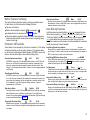
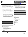
Form A Supplemental Instructions:
System Configuration
Salesperson completes items 1–11.
Sales Support Representative completes items 12–14.
7. System Lines
Enter information about individual lines in the table. Be sure to list the lines
assigned to all extensions first, followed by personal and dedicated lines.
Write R If Rotary (Dial Pulse) Line {#201}
Leave blank for touch-tone lines.
Line Coverage—You can select one per line
If desired, identify an automated answering option for incoming calls on
each line. (If all calls on a line should be covered by a human operator,
leave all line coverage columns blank for that line.) To avoid confusing
callers, It Is recommended that only one of the AA, DXD, or VMS-AA
options be used to handle Incoming calls throughout the system.
AA
DXD
VMS-AA
ASA
Hunt Group
VMS-Mail
Automated Attendant service by PARTNER Attendant, which
must be purchased separately.
Direct Extension Dialing (PARTNER II system only) lets
callers dial extensions without waiting for the receptionist.
Automated Attendant service of PARTNER MAIL™ or
PARTNER MAIL VS™, which must be purchased separately. If
the receptionist does not answer an incoming call, VMS-AA
lets the caller select an extension or route.
Automatic System Answer (PARTNER II system only) plays a
recorded message and places a call on hold until the
receptionist is free.
Hunt Group sends incoming calls directly to an extension in
the specified group.
Voice Mail coverage of personal line by PARTNER MAIL or
PARTNER MAIL VS, which must be purchased separately.
Sends unanswered incoming calls directly to the line owner’s
mailbox.
2
Write User’s Name for Personal Line
or Identify Equipment for Dedicated Line
For a personal or a dedicated line, write the user name or equipment
description (for example, “Fax”); otherwise, leave blank. (If another user
provides backup call coverage on the line, note the name of that user in
parentheses.) Use Form B2 to record custom extension assignments.
Check If Caller ID Service
(PARTNER II system only) Check this column to indicate lines on which
local telephone company Caller ID service is provided. For dial-code
features that support this service, see Form C.
8. System Settings
Receptionist answers calls during business hours?
If “Yes,” be sure to record settings on these forms that will allow
the receptionist to answer the phone before automatic coverage is applied.
Number of Lines {#104}
This programming should be used only for installation—using it later erases
custom settings for all extensions. Use Line Assignment {#301} to assign
lines after installation.
Transfer Return Rings {#105}
By default, a transferred call that is not answered within 4 rings returns to
the transfer return extension (see Write Transfer Return Ext. No. {#306} on
Form B1). To change the default, write the preferred number of rings (0–9).
For no return, write “0”.
Outside Conference Denial {#109}
To prevent all users from conferencing with more than one outside party,
write “No” in the space provided.
Toll Call Prefix {#402}
If dialing a “0” or “1” to make toll calls is not required, write “No” in the
space provided.
System Password {#403}
If a System Password is desired, write the 4-digit password. Whoever
knows the password can place any type of call at any time, regardless of
dialing restrictions.
NOTE: If a System Password is programmed, it must be entered to turn
Night Service on and off. Also, users at Night Service Group extensions
must enter the password before placing outside calls—except Marked
System Speed Dial numbers and numbers on the Emergency Phone
Number List.
9. Coverage
DXD
If DXD was specified in Item 7, write the number of times that the telephone
should ring before the system answers the call and the message callers
should hear when the system answers. Be sure to specify a Direct Extension
Dial Button {#113} for extension 10 on Form C to activate this feature.
VMS-AA
If VMS-AA was specified in Item 7, specify the VMS Hunt Delay and the
VMS Hunt Schedule:
■
VMS Hunt Delay {#506}
Check “Delayed” if the receptionist is to handle incoming calls; Voice
Mail Service will answer calls if the receptionist is busy. Check
“Immediate” if Voice Mail Service is to handle all incoming calls.
■
VMS Hunt Schedule {#507}
Specify when Voice Mail Service should answer incoming calls.
ASA
If ASA was specified in Item 7, write the number of times that the telephone
should ring before the system answers the call and the message callers
should hear when the system answers. Be sure to specify an Automatic
System Answer Button {#111} for extension 10 on Form C to activate this
feature.
10. Auxiliary Equipment (System)
Check boxes that apply for auxiliary equipment connected to the control unit or
to system wiring:
Music on Hold {#602}
It is recommended that customers who purchase a PARTNER MAIL or
PARTNER MAIL VS system use this feature so that callers hear music or
recorded messages (rather than silence) when the voice mail system
transfers their call. This feature also requires a music on hold audio source.
SMDR Record Type {#608}
If a call-reporting device (such as a printer or call accounting processor) is
connected, indicate whether information should be collected for all calls
or for outgoing calls only.
Loudspeaker Paging
If a loudspeaker paging system connected to the control unit supports
multiple zones, indicate the number of zones.
Uninterruptible Power Supply
If the customer cannot afford to lose the PARTNER II system, PARTNER
Plus system, PARTNER MAIL, or PARTNER MAIL VS configuration
information due to a power loss, an uninterruptible power supply (UPS)
should be ordered.
Caller ID Devices
If the customer wants to connect a Caller ID device (such as a PC to
process Caller ID information) directly to a system line, check this box.
Separate wiring runs are required to connect each device directly to the
network interface jack for a line.
11. Notes
Write any additional information that you wish to communicate to the installer.
3
4
Form B1 Supplemental Instructions:
System Extensions
This form provides basic information for each system extension. To customize
line restrictions or other extension settings, you must also use Form B2.
Write Name/Description
Write a user name or a description for auxiliary equipment (such as “Fax,”
“VMS,” or “Conference Room”) to be installed at the extension. If system display
phones should show the name/description of the caller for internal calls, check
the Check if Ext. Name Display {CTP} column and write the 12 characters you
want to display.
For a hotline extension, write “Hotline” in this column and write “T” for
touch-tone or “R” for rotary in the Standard column (under Identify Telephone)
to indicate the phone type. (A hotline extension should have a standard touchtone or rotary phone; an alert extension can have any phone type.)
Identify Telephone Attached to this Extension
Check the appropriate column to indicate the type of phone.
If a system and standard phone are combined on an extension, check the two
appropriate Identify Telephone columns. If a phone and an auxiliary device are
combined on the extension, check the appropriate Identify Telephone and
Identify Auxiliary Equipment columns.
Identify Auxiliary Equipment
Attached to this Extension
Except as noted, check the appropriate column to indicate the type of auxiliary
equipment.
Extra Alert
Check the extensions to which an extra alert, such as a light or bell, is
connected.
IROB
Check the extensions to which an In-Range Out-of-Building protector is
connected to prevent electrical surges.
AA Extension {#607}
Check the extension to which a PARTNER Attendant is connected.
Write Transfer Return Ext. No. {#306}
By default, a transferred call returns to the originating extension if the call is not
picked up. To specify a different transfer return extension, write the extension
number in this column. For extensions where you are connecting a PARTNER
MAIL system, PARTNER MAIL VS system, or PARTNER Attendant, indicate a
transfer return extension—usually extension 10—where an actual person can
pick up calls that are transferred by the VMS or AA extension but not answered.
If DXD line coverage is used (see Form A), you should also specify a transfer
return extension for extension 10 to provide backup coverage for calls that are
not answered at extension 10 or at an extension that the caller selects.
Line Ringing {CTP}
The default is immediate ringing for all lines at all extensions. For each extension, specify the lines that should ring after a delay (about 20 seconds) or that
should not ring. Also specify the lines that should not be assigned.
Settings for a Receptionist’s Extension
Check the 2 or 4 extensions used to connect the PARTNER MAIL system
and write “VMS” in the Write Name/Description column.
If a receptionist at extension 10 is to answer calls, coordinate line assignments
and line ringing for extension 10 with settings for other extensions, to determine how incoming calls are handled.
NOTE: In addition to the VMS extensions, you must specify an extension
■
If the receptionist is to answer all calls (Immediate call handling), assign all
lines to extension 10 with immediate ringing; assign lines as needed to other
extensions with no ringing. The receptionist will answer all calls and transfer
them to the appropriate extensions. If you want another extension to provide
backup coverage for the receptionist, assign all lines to that extension with
delayed ringing.
■
If the receptionist is to answer calls only when users do not pick up immediately (delayed call handling), set lines to immediate ringing at user extensions and to delayed ringing at extension 10.
PARTNER MAIL
(with no lines assigned) where a remote maintenance device is installed.
Write “VMS-RMD” in the Write Name/Description column.
PARTNER MAIL VS
Check the 2 extensions used for PARTNER MAIL VS and write “VMS” in the
Write Name/Description column. Note that the PARTNER MAIL VS module
is installed in a control unit slot, and so takes up 6 extensions. Only the
bottom 2 extensions, however, answer VMS calls—the other 4 can be used
as guest mailboxes.
Form B2 Supplemental Instructions:
Customized Extension Settings
Each row on Form B2 specifies settings—including group assignments—that
can be copied to other extensions using Copy Settings {#399}. Default settings
are shown at the top of Form B2.
Settings for Auxiliary Equipment
The following settings may be useful for auxiliary equipment:
■ For a dedicated line (such as a Fax line), assign the line to the equipment
extension and remove it from other extensions (see Form B1).
■ To prevent other extensions from interrupting calls, write “A (Assigned) in
the Automatic Extension Privacy {#304} column.
■ In general, do not assign auxiliary equipment extensions to a Pickup Group,
Calling Group, Hunt Group, or Night Service Group.
Identify Extension Settings if Different than
Default
For each extension, identify extension settings that are different than the
default.
Display Language {#303}
(For system display phones only) Indicate the language for display messages if different than English.
Automatic Extension Privacy {#304}
By default, any user sharing a line can join calls at another extension
(Privacy is Not Assigned). If all calls are to be private, write “A” (Assigned) in
this column. Always use this feature for Fax and modem extensions.
Abbreviated Ringing {#305}
(System phones only) By default, a new call rings only once when a phone
is in use (Abbreviated Ringing is Active); the line button light flashes until the
call is answered or the caller hangs up. To change the default so a new call
rings repeatedly, write “NA” (Not Active) in this column.
Forced Account Code Entry (#307)
(System phones only) If a user should be required to enter an account code
before placing an outside call, write “A” (Assigned) in this column.
Automatic VMS Cover {#310}
If PARTNER MAIL or PARTNER MAIL VS is installed and an extension
should automatically be covered when its calls are not answered, write “A”
(Assigned) in this column. To program a VMS Cover button to turn coverage
on and off at an extension, see Form C.
Emergency Telephone {#311}
To identify an extension as an Emergency Telephone, write “A” (Assigned) in
this column. Record the telephone number that is dialed automatically from
this extension using Emergency Telephone {#311} on Form D.
Voice Interrupt on Busy {#312}
To identify an extension as being eligible for intercom calls while busy with
another intercom or outside call, write “A” (Assigned) in this column.
Identify Restrictions/Permissions
The default setting for all extensions and lines is no restrictions. Specify restrictions and permissions for each extension.
Line Access Restriction {#302}
Write the line numbers to be restricted in the Out, In, and No columns, as
follows:
Out – Outgoing calls only—can place outside calls and receive only
transferred calls on specified line
In – Incoming calls only—cannot place outside calls on specified line
No – No access—cannot place or receive outside calls on specified line
(but if line is assigned, button lights show calling activity)
Outgoing Call Restriction {#401)
Write “In” or “Loc” to indicate restrictions for all outgoing calls on all lines at
that extension, as follows:
I n – User can make only intercom calls to other system extensions
Loc – User can make only intercom and local outside calls (no toll calls)
Any available outside lines can still be used to dial numbers on an Allowed
Phone Number List assigned to the extension, numbers on the Emergency
Phone Number List, or Marked System Speed Dial numbers.
Distinctive Ringing {#308}
By default, outside, intercom, and transferred calls each have their own
ringing pattern (Distinctive Ringing is Active). To change the default so that
all calls ring the same. write “NA” (Not Active) in this column.
5
6
Identify Group Assignments
To assign extensions to any of the following groups (each extension can be in
one or more groups), write the group number or place a check mark in the
appropriate columns.
Pickup Group Extensions {#501}
Any extension can answer an outside call ringing at an extension in the
Pickup Group, without knowing which extension is ringing and without being
in the group. For PARTNER II systems only, this also applies to intercom
and transferred calls.
Calling Group Extensions {#502}
A user can ring or page (voice signal) all extensions in a Calling Group
simultaneously (or for PARTNER II systems only, transfer a call by ringing
the group). Once an extension answers, the ringing or paging stops at the
other extensions in the group. Do not assign extensions connected to
auxiliary equipment or Emergency Telephones to a calling group.
NOTE: When the user voice signals an extension that has a system phone,
the phone beeps and the user’s voice is heard through its built-in speaker.
System phones are the only ones that can be voice signaled.
Hunt Group Extensions 1–6 {#505}
Calls can ring or be transferred to the first non-busy extension in a Hunt
Group. A call rings at an extension in a Hunt Group three times; if it is not
answered, it hunts to the next non-busy extension, continuing until someone
answers or the caller hangs up. (If you voice signal a Hunt Group, only the
first extension is signaled; the call does not keep hunting if there is no
answer.) Incoming calls on specific lines can be directed to a Hunt Group
using Group Call Distribution {#206}.
VMS Only (Hunt Group 7)
For an extension where PARTNER MAIL or PARTNER MAIL VS is connected, check this box to assign the extension to Hunt Group 7. The system
recognizes any extensions” assigned to Hunt Group 7 as Voice Mail Service
(VMS—either PARTNER MAIL VS or PARTNER MAIL VS) extensions. Do
not assign any extensions other than VMS extensions to Hunt Group 7.
Also, do not assign PARTNER MAIL or PARTNER MAIL VS extensions to
any other Hunt Groups, to any Calling or Pickup Groups, or to the Night
Service Group.
Night Service Group Extensions {#504}
Check this box if the extension should be in the Night Service Group. When
Night Service is on, incoming calls on assigned lines ring immediately at the
extensions in the Night Service Group, even if Line Ringing for those
extensions is set for “delayed ring” or “no ring”. Do not put PARTNER MAIL
or PARTNER MAIL VS extensions in the Night Service Group.
Form C Supplemental Instructions:
Button Templates
There are five pages to Form C—one page for each type of system phone and
one page for Intercom Autodialers. Use Form C to record line assignments and
to indicate programming for system telephone buttons that do not have lines
assigned if the programming is to be performed from extension 10 or 11 during
system installation. After installation, users can program additional features
using the instructions in their Quick Reference cards.
A telephone button can be programmed as a line button (to access an outside
line), as an Auto Dial button (to dial a phone number or a PBX/Centrex feature
access code with one touch), or as a dial-code feature button (to access a
dial-code feature with one touch). Line buttons must have status lights; some
features also require buttons with lights (see “Button Feature Summary”).
Using the information from Line Ringing on Form B1 and Line Access Restriction on Form B2, fill out Form C as follows:
■
Make as many copies of each page of Form C as you need. Where line and
button assignments are identical for two or more phones of the same type,
you can use one copy of the form and indicate the extension numbers
sharing the programming in the space provided at the bottom of the form.
■
Use either the button template (to record the exact location of buttons and
the programming assigned to them) or the Check Desired Features checklist
(to identify features to be programmed), or both. By default, lines are
assigned to buttons in the following order:
34-Button Telephone
27
21
15
9
5
1
28
22
16
10
6
2
29
23
17
11
7
3
30
24
18
12
8
4
31
25
19
13
32
26
20
14
18-Button and 12-Button Telephones. NOTE: On 12-button phones,
only buttons 1–10 have Iights.
13
9
5
1
14
10
6
2
15
11
7
3
16
12
8
4
3
4
■
Indicate the order in which a line is selected when the user lifts the handset
or presses [ Spkr ] to place a call without first pressing a line button (Automatic
Line Selection) if the order is to be different than the default (outside lines in
ascending numerical order followed by intercom).
Intercom Autodialer
The buttons on an Intercom Autodialer are automatically programmed as
Intercom Auto Dial buttons for all system extensions in the following order:
Intercom Autodialer 1
10
11
12
13
14
15
16
17
18
19
20
21
22
23
24
25
26
27
28
29
30
31
32
33
Intercom Autodialer 2
(PARTNER II system only)
34
35
36
37
38
39
40
41
42
43
44
45
46
47
48
49
50
51
52
53
54
55
56
57
Individual buttons can be reprogrammed to ring or voice signal the extension.
On PARTNER II systems only, the buttons can be programmed to ring, voice
signal, or manually signal; and you can change the order. On both PARTNER
Plus and PARTNER II systems, only one button (on both the phone and
Intercom Autodialer) can be programmed for each extension.
6-Button Telephone
1
2
7
8
Example Templates
Auto Dial and Manual Signaling buttons for 45 extensions; the order of
extensions has been changed to begin with extension 11 on the top left button
on the first Autodialer. The user’s 18-button telephone has only 8 lines
assigned; the other 8 buttons are used for Intercom Auto Dialing and dial-code
features.
These examples show a 34-button telephone and Intercom Autodialers
programmed for a PARTNER II system receptionist, and an 18-button
telephone programmed for a PARTNER II system user. Buttons that are not
used for lines have dial-code features. (The abbreviations are explained in
“Button Feature Summary” beginning on page 9.) The 34-button telephone has NOTE: Shaded areas indicate features that are available only on a PARTNER II
16 lines assigned, and the Intercom Autodialers are programmed with Intercom system.
34-Button Telephone
18-Button Telephone
Intercom Autodialers
Button Feature Summary
This section lists button features in order by feature type and feature name.
For each feature, the first line shows the following information:
■ The name of the feature.
■
Whether a button with lights is required (
) or recommended (
).
An abbreviation that can be entered on the Form C templates.
The entries needed to program the feature on a button. Some features can
include a two-digit extension number (shown as xx) or a single-digit group
number (shown as g).
Wake
Wake Up Service Button
{#115}
Allows the user at extension 10 to schedule an intercom call to a target extension at a
designated time. If Music on Hold {#602} is active, music is played when the phone is
answered; otherwise, nothing is heard.
Auto Dialing Features
Extension 10 Features
Auto Dial numbers can include the digits [ 0 ]–[ 9 ], [ ★ ], [ # ], and special functions
that you store by pressing [ Hold ] (Pause), [ Mic ] (Stop), [ Spkr ] (Recall), and [ Transfer ]
(Touch-Tone Enable).To store an intercom number, you must press the left
[ Intercom ] button before entering the extension number. Only one Auto Dial
number for an extension can be stored on the buttons available at an extension
for both the phone and Intercom Autodialer.
These features can be assigned only to the phone at extension 10. Auto dialing
and dial-code features can also be used at extension 10; of particular interest
are the Intercom Auto Dialing and Manual Signaling (PARTNER II system only)
features, which use button lights to show extension calling activity.
Auto Dialing (Outside Phone Number)
xxx-xxxx
Places a call to an outside telephone number. Outside telephone numbers can be
up to 20 digits. If a dial-out code is required to dial outside numbers (for example, on
PBX or Centrex lines), include it in the stored number.
■
■
ASA
{#111}
Automatic System Answer Button
(PARTNER II system only) Turns Automatic System Answer on and off. When the
feature is on, a call that is not answered by the receptionist is answered by the
system; the system plays a brief message, then places the call on hold for later
retrieval. To use Automatic System Answer, extension 10 must be programmed with
an ASA button.
DXD
{#113}
Direct Extension Dial Button
(PARTNER II system only) Turns Direct Extension Dial on and off. When the feature
is on, a call that is not answered by the receptionist is answered by the system; the
system plays a brief message, then lets the caller dial an extension number or wait
for the receptionist. To use Direct Extension Dialing, extension 10 must be
programmed with a DXD button.
NightSvc
{#503}
Night Service Button
Turns Night Service on and off. Phones in the Night Service Group ring immediately
when the feature is active, regardless of normal ringing. To use Night Service,
extension 10 must be programmed with a Night Service button. Night Service Group
extensions should be identified on Form B2.
xxx (NAME)
Auto Dialing (PBX/Centrex Feature Code)
Dials a PBX/Centrex feature code. To program the button so that you can access
the feature while on a call, specify “R” on Form C before the feature code, and
include the Recall signal on the Auto Dial button.
Fax-x x
Fax Management
[ Intercom ] x x
Transfers calls to the fax machine at the designated extension with one touch. If on
a button with lights, the lights show when the fax is busy or when it is having trouble
and not answering—for example, when it is out of paper.
Ext-x x
Intercom Auto Dialing—Ring
[ Intercom ] xx
Places a ringing intercom call to an extension, or transfers a call. If on a button with
lights, the lights show calling activity at the destination extension.
ExtVS-x x
Intercom Auto Dialing—Voice Signal
[ Intercom ] [ ★ ] x x
Places a voice-signaled intercom call to the extension’s phone speaker, or transfers
a call with a voice-signaled announcement. If on a button with lights, the lights show
calling activity at the destination extension.
OCR
{#114}
Outgoing Call Restriction Button
Allows the user at extension 10 to change the outgoing call restriction for a particular
extension. An Auto Dial button with lights must be programmed for each extension to
be changed.
9
10
Manual Signaling—Ring
MS-xx
[ Feature ] [ 1 ] [ 3 ] xx
(PARTNER II system only) Beeps the designated extension. If you press [ Intercom ]
first, pressing the button places a ringing intercom call to the extension, or transfers
a call. If on a button with lights, the lights show calling activity at the destination
extension.
Manual Signaling—Voice Signal
MSVS-xx
[ Feature ] [ 1 ] [ 3 ] [ ★ ] xx
(PARTNER II system only) Beeps the designated extension. If you press [ Intercom ]
first, pressing the button places a voice-signaled intercom call to the extension, or
transfers a call with a voice-signaled announcement. If on a button with lights, the
lights show calling activity at the destination extension.
Dial-Code Features
Account Code Entry
ACE
[ Feature ] [ 1 ] [ 2 ]
Allows a user to enter an account code for’s call by pressing the button, entering up
to 16 digits for the account code, then pressing the button again. If on a button with
lights, the lights show when the feature is in use.
Background Music
Music
[ Feature ] [ 1 ] [ 9 ]
Turns background music on and off at the speaker of an idle system phone.
Call Forwarding/Call Follow-me
CF(xx xx)
[ Feature ] [ 1 ] [ 1 ] xx xx
Forwards all calls to the designated extension. If on a button with lights, the lights
show when the feature is in use. Unless Do Not Disturb is on, phone beeps once
each time a call is forwarded. Do not forward calls to extensions in Hunt Group 7.
For PARTNER II system only, you may program source and destination extension
numbers on the button.
Call Pickup
Pickup- xx
Picks up a call ringing at the designated extension.
[ Intercom ] [ 6 ] xx
Caller ID Inspect
[ Feature ] [ 1 ] [ 7 ]
ID-lnspect
(PARTNER II system only) When a user at a display phone is already on a call, this
feature shows Caller ID information for another line (if Caller ID information is
available on that line), without disconnecting the current call or putting it on hold.
When the feature is active, the button light is on.
lD-Name
Caller ID Name Display
[ Feature ] [ 1 ] [ 6 ]
(PARTNER II system only) When a user at a display phone is on a call on a line that
has Caller ID information available, this feature lets the user switch between the
caller’s telephone number (the default display) and the caller’s name (if available).
When the feature is active—indicating that the caller’s name should be displayed—
the button light is on.
Conference Drop
Drop
Drops the last outside party added to a conference call.
[ Feature ] [ 0 ] [ 6 ]
Direct Line Pickup—Active Line
DLPA
[ Intercom ] [ 6 ] [ 8 ]
Allows you to access a ringing, active, or held call on a line that is not assigned to
the extension. Direct Line Pickup is subject to Line Access Restrictions programmed
for the extension.
Direct Line Pickup—Idle Line
DLPI
[ Intercom ] [ 8 ]
Allows you to access an idle (non-busy) line that is not assigned to the extension.
Direct Line Pickup is subject to Line Access Restrictions programmed for the
extension.
Do Not Disturb
DND
[ Feature ] [ 0 ] [ 1 ]
Prevents calls from ringing at the extension. When the feature is active, the button
light is on. Transferred calls return to sender, intercom calls get a busy signal, and
outside callers hear ringing. Use only if someone else answers the extension’s
outside calls. If VMS Cover and Do Not Disturb are both active, intercom and
transferred calls go directly to the extension’s voice mailbox.
Exclusive Hold
ExHold
[ Feature ] [ 0 ] [ 2 ]
Places a call on hold and prevents other extensions with the line from picking it up.
Group Calling—Page
GCallP-g
[ Intercom ] [ ★ ] [ 7 ] g
Places a voice-signaled intercom call to all extensions in the designated Calling
Group (no transfer capability). The caller is connected to the first extension that
answers.
Group Calling—Ring
GCall-g
[ Intercom ] [ 7 ] g
Places a ringing intercom call to all extensions in the designated Calling Group. The
caller is connected to the first extension that answers. For PARTNER II system only,
can be used to transfer a call to an extension in the group.
Group Hunting—Ring
Hunt-g
[ Intercom ] [ 7 ] [ 7 ] g
Rings the first available extension in the designated Hunt Group, or transfers a call
to an extension in the group. If unanswered after 3 rings, the call moves to the next
available extension, and so on, until the call is answered or until the caller hangs up.
Group Hunting—Voice Signal
HuntVS-g
[ Intercom ] [ ★ ] [ 7 ] [ 7 ] g
Voice signals the first available extension in the designated Hunt Group, or transfers
a call to the extension with a voice-signaled announcement. The caller is connected
only if that extension answers.
Group Pickup
[ Intercom ] [ 6 ] [ 6 ] g
P/U Grp-g
Picks up an outside call ringing at any extension in the designated Pickup Group.
For PARTNER II system only, applies to intercom and transferred calls as well.
LNR
Last Number Redial
[ Feature ] [ 0 ] [ 5 ]
Automatically redials the last outside number dialed up to a maximum of 20 digits.
This feature can be used to redial only the last outside number dialed.
VIOB
Voice Interrupt on Busy Talk-Back
[ Feature ] [ 1 ] [ 8 ]
Lets user respond to voice interrupt on busy call while still active on the existing call.
Loudspk
Loudspeaker Paging
[ Intercom ] [ 7 ] [ 0 ]
Connects you to the loudspeaker paging system, if one is connected to the system.
Voice Mail Messages
VMMsgs-777 [ Intercom ] [ 7 ] [ 7 ] [ 7 ]
Places an intercom call to the PARTNER MAIL or PARTNER MAIL VS system (if
available), so that a user can check messages, send messages, or administer
greetings.
[ Feature ] [ 1 ] [ 0 ] xx
MsgOff-xx
Message Light Off
Turns off the message light on the phone at the designated extension. For
PARTNER II system only, you may also program an extension number on the
button.
VMBox
Voice Mailbox Transfer
[ Feature ] [ 1 ] [ 4 ]
Transfers a caller directly to a specific extension’s voice mailbox, so that the caller
can leave a message without having to first ring the extension.
Message Light On
[ Feature ] [ 0 ] [ 9 ] xx
MsgOn-xx
Turns on the message light on the phone at the designated extension. For
PARTNER II system only, you may also program an extension number on the
button.
Priv
Privacy
[ Feature ] [ 0 ] [ 7 ]
Prevents other people with the same line from joining calls being conducted at this
extension. When the feature is active, the button light is on. This feature overrides
Automatic Extension Privacy {#304}.
Recall
Recall
[ Feature ] [ 0 ] [ 3 ]
“Recalls” a dial tone to access a PBX/Centrex feature while on a call on a PBX/
Centrex line (pressing Recall disconnects an intercom call).
SNR
Save Number Redial
[ Feature ] [ 0 ] [ 4 ]
This feature can be programmed onto more than one button. Using this feature
while on an outside call saves the number dialed into temporary memory. The
number stays in memory until a different one is saved; this feature can be used
again to redial the number at any time. (Unlike Last Number Redial, you must use
this feature to save the number as well as to redial it; Save Number Redial lets you
make other outside calls before redialing the saved number.) Account codes cannot
be saved and redialed using this button.
TT-EN
Touch-Tone Enable
[ Feature ] [ 0 ] [ 8 ]
Lets users with rotary lines access phone services that require touch-tone digits. For
example, after calling a bank-by-phone service and being prompted to enter touchtone digits, using this feature changes the digits dialed to touch tones for the rest of
the call.
[ Feature ] [ 1 ] [ 5 ]
VMS Cover
VMSCover
Turns voice mail coverage for the extension on and off if PARTNER MAIL or
PARTNER MAIL VS is installed. When the feature is active, the button light is on.
11
12
Form D Supplemental Instructions:
Number Lists
Use this form to specify lists of Disallowed, Allowed, and Emergency telephone Disallowed Phone Number Lists {#404}
numbers. Also use this form to identify the phone numbers dialed automatically With Disallowed lists, you can prevent users from dialing specific telephone
by emergency telephones.
numbers or categories (for example, calls to 976 exchanges for pre-recorded
messages such as horoscopes, and calls to 900 area code “chat lines”).
NOTE: To restrict long-distance calling, Toll Call Prefix {#402} (indicating
whether you must dial a 0 or 1 to place long distance calls) must be set corExamples of Disallowed List Entries
rectly (see Form A).
Preventing Calls to 976 Exchange Numbers
In this example, !0! and !1! represent “any area code.”
Creating Disallowed and Allowed Lists
if 0 or 1 toll prefix
Entries needed . . . if 0 or 1 toll prefix
You can create up to 4 lists each of Disallowed and Allowed telephone numis not required
is required
bers. Each list can have up to 10 numbers; each number can be up to 12 digits
976
976
long, including the digits [ 0 ]–[ 9 ], [ Hold ] (to represent any single digit), and for the
!0!976
0976
PARTNER II system only, [ ★ ] and [ # ].
!1!976
1976
0!1!976
1. Under the List number, write a name for the list (for example, “Suppliers”).
0!0!976
2. In the “Telephone Number” column, write the entries for the list. You can
1!1!976
specify complete telephone numbers or categories of numbers.
1!0!976
■ To specify a complete number, write it exactly as it would be dialed,
Preventing Calls to 900 Area Code
including (if needed) a dial-out code, toll call prefix, and area code.
if 0 or 1 toll prefix
Entries needed . . . if 0 or 1 toll prefix
■ To specify a category, provide one or more entries to describe an entire
is not required
is
required
class of calls (such as an area code or local exchange). Preventing calls
900
0900
to a category may require more than one entry, to allow for different ways
1900
of dialing a number (see “Examples of Disallowed List Entries”).
After a list has been created, it can be assigned to an extension (see Form B2).
Preventing International (011) Calls
Entry needed . . .
011
Allowed Phone Number Lists {#407}
Allowed telephone numbers are exceptions to restrictions. For example, you might
put 976 numbers on a Disallowed list, but allow dialing of 976-1212 for weather
reports. Or you might restrict an extension to local dialing only, but assign an
Allowed list to permit the user to call specific customers or suppliers.
Emergency Phone Number List {#406}
Forced Account Code List {#409}
You can create a list of emergency numbers that can be dialed at any time by
any extension that has access to an outside line. The list can have up to 10
entries; each entry can be up to 12 digits long, including the digits [ 0 ]–[ 9 ].
Emergency numbers override all other dialing restrictions, including Night
Service with a System Password.
If an extension has been designated for Forced Account Code entry on Form
B2, the user must dial an account code before an outside telephone number
can be dialed. Account codes, each up to 16 digits in length, can be used
to associate telephone calls with a particular department or client. Account
codes print on SMDR call reports and on reports generated by call accounting
packages.
NOTE: Various factors influence the effectiveness of dialing restrictions. Avoid
putting 800 numbers in your Emergency Phone Number List. If you need to
allow restricted users to access 800 numbers, put those numbers in an Allowed Phone Number List instead.
Important Notices
■
■
Consult your local phone directory to determine the numbers for police, fire,
and ambulance service, because “911” is not available everywhere.
When programming emergency numbers and/or making test calls to
emergency numbers:
1. Stay on the line and briefly explain to the dispatcher the reason for the
call before hanging up.
2. Perform such activities during off-peak hours, such as in the early
morning or late evening.
If Forced Account Code Verification is desired, entries must be made in the
Forced Account Code List {#409}. When the system verifes an account code, it
compares only the first six digits of the user-entered account code to the entries
in the Forced Account Code List. For a match to be successful, the user must
dial at least the account code’s associated list entry, even though the user can
dial up to 16 digits for an account code.
Example Emergency List
911
611 (local
555–2345
555–4567
555–1357
phone company service)
(Boss’s home)
(auto club)
(company doctor)
Emergency Telephone {#311}
For each extension that has been designated as an Emergency Telephone on
Form B2, write the telephone number that is dialed automatically when the
handset is lifted. The telephone number can be up to 20 digits.
13
14
Form E Supplemental Instructions:
Speed Dial Numbers
With Speed Dialing, a user can dial a stored number by pressing three buttons:
the [ Feature ] button ([ # ] on a standard phone) followed by a 2-digit code. Storing a
telephone number as a Speed Dial number lets users dial more quickly. Other
kinds of numbers—such as account codes and other dialing sequences—can
also be stored as Speed Dial numbers. The system allows up to 60 System
Speed Dial numbers that everyone on the system can use, as well as up to 20
Personal Speed Dial numbers for each extension (for the personal use of the
extension user). Users should record their Personal Speed Dial numbers on
their Quick Reference card.
Write Telephone Number
Write the number exactly as it should be dialed. Numbers can be up to 20
digits, including the digits [ 0 ]–[ 9 ], [ ★ ], [ # ], and the special dialing functions
discussed next. To store a telephone number, include the dial-out code,
toll-call prefix, and area code (if needed), along with the number.
Please have the System Speed Dial Numbers form filled out when the
technician arrives to install the system. After installation, photocopy this form
and distribute a copy to everyone using the system. Users should keep this
form near their phones for reference when placing calls.
Pause
Special Dialing Functions
Function
Button to Press
Display
Description
[ Hold ]
P
Pauses for 1.5 seconds
before dialing the rest of the
stored number
Recall
[ Spkr ]
R
Sends a timed switchhook
flash (useful for your
telephone company’s
custom calling features)
Stop
[ Mic ]
S
Interrupts the dialing
sequence until the code is
dialed again
Touch-tone Enable
[ Transfer ]
T
Sends touch tones on a
rotary line
General Guidelines
Each System Speed Dial number is assigned a 2-digit code from 20–79. For
example, suppose the staff frequently calls Acme Supplies and Acme’s telephone number is stored for code 20. To call Acme, a user simply dials [ Feature ]
[ 2 ] [ 0 ]. If Acme moves, or the phone number changes, program the new telephone number and users still dial [ Feature ] [ 2 ] [ 0 ] to reach them.
Record the following information for each System Speed Dial number:
Write Name/Company
Write the name of the person or company to which the number belongs. For
other types of numbers, such as account codes, enter a description of the
number.
Column (Marked System Speed Dial Numbers)
If users should be able to call a particular System Speed Dial number,
regardless of any dialing restrictions placed on their extensions, “mark” the
number so it can be dialed at all times. Mark the number by placing a check
mark in this column, and by pressing [ ★ ] before the number when storing it.
For marked numbers, the stored number does not appear on a display
phone when a user dials the Speed Dial code. Account codes cannot be
marked.
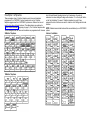
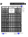
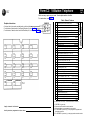
Form A: System Configuration
AT&T
PAGE
1 of 2
Required for PARTNER II system and PARTNER Plus system.
For additional instructions, see page 2.
6. Features Customer is most interested in (most important first)
1. Customer Billing Name
2. Installation Address
3. Contact Name
4. Person to be Trained
5. Sold by
Phone
(
)
AT&T Sales Force
Alternate Trainee’s Name
–
Salesperson’s Name
Dealer:
Phone
(
)
Phone
(
)
Phone
(
)
–
–
–
7. System Lines
Line Write the Telephone Numbers
Jack in order customer desires
No. (list personal and dedicated
lines last)
Line Coverage—You can select one per line
Write R
if
A A1 D X D2 VMS- A S A4 Hunt 5 VMS- Write User's Name for Personal
Rotary
Group M a i l6 Line or Identify Equipment for
A A3
(Dial
Pulse) {#607} {#205} {#206} {#204} {#206} {#206} Dedicated Line
Line
Only one of these
{#201}
types per system
Check
if
Caller
ID
Service
Identify other Local
Telephone Company
Subscription Services
(e.g., Call Waiting)
01
02
03
04
05
06
07
08
09
10
11
12
13
14
15
16
17
18
19
20
21
22
23
24
1. Check if desired. Also see Form B1, AA Extension (#607) column.
2. Check if desired. Also see Form A, Item 9—DXD, and Form C, Direct Extension Dial Button {#113).
3. Check If desired. Also see Form A, Item 9—VMS-AA, and Form B1, PARTNER MAIL or PARTNER MAIL VS
column. Programmed using option 1 of Group Call Distribution {#206).
4. Check if desired. Also see Form A, Item 9—ASA, and Form C, Automatic System Answer Button {#111}.
5. Write group number (1–6) covering this line. Also see Form B2, Hunt Group Extensions (#505) 1–6.
Programmed using option 1 of Group Call Distribution (#206).
6. Check if desired. Also write user’s name for personal line In next column and see Form B1, PARTNER
MAIL or PARTNER MAIL VS column. Programmed using option 3 of Group Call Distribution {#206).
Form A: System Configuration
AT&T
PAGE
2 of 2
Required for PARTNER II system and PARTNER Plus system.
For additional instructions, see page 2.
8. System Settings. Write response on line for each item.
●
Receptionist answers calls during business hours? Write “Yes” or “No”
●
●
Number of Lines {#104}—number of outside lines assigned automatically to all extensions
(2 lines per 208 module and 4 lines per 400 module ✔ ). Write number
Transfer Return Rings {#105}—number of times transferred call rings before returning to
the transfer return extension (0–9, 4 ✔ ). Write number if different than default
●
Outside Conference Denial {#109}—allows or disallows conference calls with up to
2 outside parties (allow ✔ ). Write “No” if 2 outside parties are disallowed.
●
Toll Call Prefix {#402}—indicates if 0 or 1 must be dialed before the area code for a
long distance call (required ✔ ). Write “No” if 0 or 1 is not required
●
System Password {#403}—password needed to turn Night Service on and off and to override dialing restrictions (no password ✔ ). Write 4 digits if password is desired
9. Coverage. Complete items based on Line Coverage selection on Form A, Item 7.
DXD: If DXD is checked, specify the following:
Direct Extension Dial Delay {#112}—number of times call should ring before it is
answered by the system (0–9, 2 ✔ ). Write number if different than the default
Direct Extension Dial Record/Playback (I 892)—message of up to 20 seconds that
caller hears when call is answered with the Direct Extension Dial feature. Write
message below and record from extension 10 or 11:
9. (Continued)
ASA: If ASA is checked, specify the following:
Automatic System Answer Delay {#110}—number of times call should ring before it is
answered by the system (0–9, 2 ✔ ). Write number if different than the default
ASA Record/Playback (I 891)—message of up to 10 seconds that caller hears
when the call is placed on hold by the Automatic System Answer feature. Write
message below and record from extension 10 or 11:
10. Auxiliary Equipment (System). Specify if applicable:
Music on Hold {#602}—check one box:
Active ✔
Inactive
SMDR Record Type {#608}—check one box:
Record all calls ✔
Record outgoing calls only
Loudspeaker Paging
Number of zones
Uninterruptible Power Supply
Caller ID Devices
11. Notes
VMS-AA: If VMS-AA is checked, specify the following:
VMS Hunt Delay {#506}—check one box:
VMS answers call immediately (Immediate ✔ )
VMS answers calls if not picked up by 4th ring (Delayed)
VMS Hunt Schedule (#507)—check one box:
VMS is on all the time (Always ✔ )
Day only
Night only
12. Installation Date
13. Order Nos.
14. Sales Support Representative’s Name
Telephone No.
✔ = default
I = Intercom button
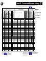
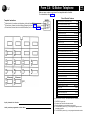
Form B1: System Extensions
AT&T
PAGE
1 of 2
Required for PARTNER II system and PARTNER Plus system.
For additional instructions, see page 4.
Identify Telephone
Attached to this Extension
Identify Auxiliary Equipment
Attached to this Extension
Line Ringing {CTP}
✔ = Immediate Ring
Write line numbers for Delayed,
No Ring, and Lines Not Assigned
Write Name/Description
Ext. (If Extension Name Display
Jack column is checked, use first 12
No. characters for programming)
Write in
Other
Equipment
Write
Transfer
Return
Ext. No.
{#306}
Delayed
No Ring
Lines
Not
Assigned 7
10
11
12
13
14
15
16
17
18
19
20
21
22
23
24
25
26
27
28
29
30
31
32
33
IMPORTANT: A system display phone is required for programming at extension 10 or 11. Extension 10 typically is the receptionist’s
extension. Extension 11 is recommended as a second programming extension (typically the System Manager’s extension).
1 . On a PARTNER II system, write “1” or “2” to indicate how many Intercom Autodialers are connected
to the extension.
2 . Write “T” for touch-tone or “R” for rotary.
3 . Also see Write Transfer Return Ext. No. {#306} on this form and Form B2, Hunt Group 7 (VMS Only).
✔ = default
{CTP} = Centralized Telephone
Programming
4. Also write extension number of corresponding alert extension in the next column. (Write “70” if Loudspeaker
Paging System is the Alert Extension.)
5. Also check corresponding alert extensions in the next column.
6. Also see Write Transfer Return Ext. No. {#306} on this form.
7. Programmed using Line Assignment {#301}.
Form B1: System Extensions
AT&T
PAGE
2 of 2
Required for PARTNER II system extensions 34 through 57.
For additional instructions, see page 4.
Identify Telephone
Attached to this Extension
Identify Auxiliary Equipment
Attached to this Extension
Line Ringing {CTP}
✔ = Immediate Ring
Write line numbers for Delayed,
No Ring, and Lines Not Assigned
Write Name/Description
Ext. (If Extension Name Display
Jack column is checked, use first 12
No. characters for programming)
Write
Transfer
Return
Write in
Ext. No.
Other
Equipment {#306}
Delayed
No Ring
Lines
Not
Assigned 7
34
35
36
37
38
39
40
41
42
43
44
45
46
47
48
49
50
51
52
53
54
55
56
57
1.
2.
3.
4.
For extensions 10 and 11 only.
Write “T” for touch-tone or “R” for rotary.
Also see Write Transfer Return Ext. No. {#306} on this form and Form B2, Hunt Group 7 (VMS Only).
Also write extension number of corresponding alert extension in the next column. (Write “70” if Loudspeaker
Paging System is the Alert Extension.)
5. Also check corresponding alert extensions in the next column.
6. Also see Write Transfer Return Ext. No. {#306} on this form.
7. Programmed using Line Assignment {#301}.
✔ = default
{CTP} = Centralized Telephone
Programming
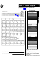
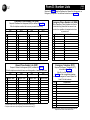
Form B2: Customized Extension Settings
AT&T
PAGE
1 of 2
Required if you want to change extension setting defaults for PARTNER II
system and PARTNER Plus system. For additional instructions, see page 5.
Identify
Restrictions/Permissions
Identify Extension Settings
if Different than Default
E ✔ NA ✔ A ✔ NA ✔ A ✔ NA ✔ NA ✔ NA ✔
Identify
Group Assignments
Assignments
✔ = Default
A
= Assigned or Active
Line Access Restriction {#302}
E
= English
Write line numbers for outgoing calls
only (Out), incoming calls only (In),
or no access (No).
NA = Not Assigned or
Not Active
Out
NR ✔
In
NR = No Restriction
No
NR ✔
1–4 1 – 4 1–4 1–4 1–6 7
NA ✔
NA ✔
NA ✔
NA ✔
10
11
12
13
14
15
16
17
18
19
20
21
22
23
24
25
26
27
28
29
30
31
32
33
1. Write “S” for Spanish or “F” for French.
2. Also see Form D—Emergency Telephone {#311}.
3. Write “In” for Inside Only or “Loc” for Local Only.
4. Write list numbers (1–4). Also see Form D—Disallowed Phone Number Lists {#404}.
5 . Write list numbers (1–4). Also see Form D—Allowed Phone Number Lists {#407}.
6 . Write group numbers (1—4).
7 . Write group numbers (1–6).
Form B2: Customized Extension Settings
AT&T
PAGE
2 of 2
Required if you want to change extension setting defaults for PARTNER II system
extensions 34–57. For additional instructions, see Page 5.
Identify
Identify
Assignments
Group Assignments
Restrictions/Permissions
Identify Extension Settings
if Different than Default
✔ = Default
A
Line Access Restriction {#302}
= Assigned or Active
E = English
Write line numbers for outgoing calls
only (Out), incoming calls only (In),
or no access (No).
NA = Not Assigned or
Not Active
NR = No Restriction
E ✔ NA ✔ A ✔ NA ✔ A ✔ NA ✔ NA ✔ NA ✔
Out
NR ✔
In
No
1 – 4 1–4 1–4 1 – 4 1–6 7
NA ✔
NR ✔
NA ✔
NA ✔
NA ✔
34
35
36
37
38
39
40
41
42
43
44
45
46
47
48
49
50
51
52
53
54
55
56
57
1 . Write “S” for Spanish or “F” for French.
2 . Also see Form D—Emergency Telephone {#311}.
3 . Write “In” for Inside Only or “Loc” for Local Only.
4 . Write
5 . Write
6 . Write
7 . Write
list numbers (1–4). Also see Form D—Disallowed Phone Number Lists {#404}.
list numbers (1–4). Also see Form D—Allowed Phone Number Lists {#407}.
group numbers (1–4).
group numbers (1–6).
PAGE
1 of 5
Form C1: 34-Button Telephone
AT&T
Make as many copies as you need. Use template and/or checklist.
For instructions, see page 7.
Check Desired Features
SAMPLE
Template Instructions
●
●
●
Automatic System Answer Button {#111}1
ASA
Direct Extension Dial Button {#113}1
Night Service Button {#503}
DXD
-
If desired, write in line number, auto dial number, or dial-code feature
For line buttons, if desired, write in Line Ringing (Delayed or No) from Form B1
For line buttons, if desired, write in Line Access Restriction (Out, In, or No) from Form B2
NightSvc
Outgoing Call Restriction Button {#114}2
OCR
Wake Up Service Button {#115}
Wake
lD-Inspect
Caller ID Inspect (F 17)1
Caller ID Name Display (F 16)1
ID-Name
DND
Do Not Disturb (F 01)
Priv
Privacy (F 07)
VMSCover
VMS Cover (F 15)
Voice Interrupt on Busy Talk-Back (F 18)
VIOB
Account Code Entry (F 12)3
ACE
Music
Background Music (F 19)
Call Forward/Call Follow-Me (F 11 XX XX)3,4
CF
Pickup-XX
Call Pickup (I 6 XX)
Drop
Conference Drop (F 06)
DLPA
Direct Line Pickup-Active Line (I 68)
DLPI
Direct Line Pickup-Idle Line (I 8)
ExHold
Exclusive Hold (F 02)
Fax-XX
Fax Management (I XX)3
Group Call-Ring/Page (I 7 G or I "7 G) GCall-G, GCallP-G
Group Hunt-Ring/Signal(I 77 G or I "77 G) Hunt-G, HuntVS-G
P/U Grp-G
Group Pickup (I 66 G)
Intercom Autodial (I XX or I "XX) 3
Ext.
Intercom
Last Number Redial (F 05)
LNR
Loudspeaker Paging (I 70)
Loudspk
Manual Signal (F 13 XX or F 13 "XX)
Intercom
Ext-XX, ExtVS-XX
Message Light Off (F 10 XX)
5
Message Light ON (F 09 XX)5
Recall (F 03)
Save Number Redial (F 04)
Touch-Tone Enable (F 08)
Voice Mail Messages Button (I 777)
Voice MailboxTransfer (F 14)
1,3
MS-XX, MSVS-XX
MsgOff-XX
MsgOn-XX
Recall
SNR
TT-EN
VMMsgs-777
VMBox
F = Feature button G = Group I = Left Intercom button XX = Extension
Specify Automatic Line Selection:
Identify extensions programmed as shown above:
1.
2.
3.
4.
PARTNER II system only.
Requires Auto Dial button for each extension.
Button with lights is recommended, but not required.
For PARTNER II system only, you can program the origination and
destination extension.
5. For PARTNER II system only, you can program the extension number.
Form C2: Intercom Autodialer
AT&T
For PARTNER II System only, make two copies if appropriate.
For additional instructions, see page 7.
Instructions for PARTNER II System
Extensions 10 and 11 each support up to two Intercom Autodialers.
● Write in extension number
● If desired, write in Ring, VS (Voice Signal), or MS (Manual Signal)
● If desired, write in user name for this extension
Instructions for PARTNER PIUS System
Extensions 10 and 11 each support only one Intercom Autodialer.
● Write in extension number
● If desired, write in Ring or VS (Voice Signal)
● If desired, write in user name for this extension
Extensions programmed as shown (circle choices): 10 11
SAMPLE
SAMPLE
PAGE
2 of 5
Form C3: 18-Button Telephone
AT&T
Make as many copies as you need. Use template and/or checklist.
For instructions, see page 7.
Check Desired Features
SAMPLE
Automatic System Answer Button {#111}
1
Template Instructions
●
●
●
PAGE
3 of 5
Direct Extension Dial Button {#113}
If desired, write in line number, auto dial number, or dial-code feature
For line buttons, if desired, write in Line Ringing (Delayed or No) from Form B1
For line buttons, if desired, write in Line Access Restriction (Out, In, or No) from Form B2
1
ASA
DXD
Night Service Button {#503}
NightSvc
Outgoing Call Restriction Button {#114}2
OCR
Wake Up Service Button {115}
Wake
Caller ID Inspect (F 17)1
lD-Inspect
Caller ID Name Display (F 16)1
lD-Name
Do Not Disturb (F01)
DND
Privacy (F 07)
Priv
VMS Cover (F 15)
VMSCover
Voice Interrupt on Busy Talk-Back (F 18)
VIOB
Account Code Entry (F 12)3
ACE
Background Music (F 19)
Music
Call Forward/Call Follow-Me (F 11 XX XX) 3,4
Call Pickup (I 6 XX)
Conference Drop (F 06)
Direct Line Pickup-Active Line (I 68)
Direct Line Pickup-Idle Line (I 8)
Exclusive Hold (F 02)
CF
Pickup-XX
Drop
DLPA
DLPI
ExHold
Fax Management (I XX)3
Fax-XX
Group Call-Ring/Page (I 7 G or I "7 G) GCall-G, GCallP-G
Group Hunt-Ring/Signal (I 77 G or I "77G) Hunt-G, HuntVS-G
Group Pickup (I 66 G)
Intercom Autodial (I XX or I "XX)3
Intercom
Intercom
Ext.
P/U Grp-G
Ext-XX, ExtVS-XX
Last Number Redial (F05)
LNR
Loudspeaker Paging (I 70)
Loudspk
Manual Signal (F 13 XX or F 13 "XX)1,3 MS-XX, MSVS-XX
Message Light Off (F 10 XX)5
MsgOff-XX
Message Light On (F 09 XX)5
MsgOn-XX
Recall (F03)
Save Number Redial (F 04)
Touch-Tone Enable (F 08)
Voice Mail Messages Button (I 777)
Voice Mailbox Transfer (F 14)
Recall
SNR
TT-EN
VMMsgs-777
VMBox
F = Feature button G = Group I = Left Intercom button XX = Extension
Specify Automatic Line Selection:
Identify extensions programmed as shown above:
PARTNER II system only.
Requires Auto Dial button for each extension.
Button with lights is recommended, but not required.
For PARTNER II system only, you can program the origination and
destination extension.
5. For PARTNER II system only, you can program the extension number.
1.
2.
3.
4.
Form C4: 12-Button Telephone
AT&T
PAGE
4 of 5
Make as many copies as you need. Use template and/or checklist.
For instructions, see page 7.
●
●
●
Check Desired Features
SAMPLE
Template Instructions
If desired, write in line number, auto dial number, or dial-code feature
For fine buttons, if desired, write in Line Ringing (Delayed or No) from Form B1
For line buttons, if desired, write in Line Access Restriction (Out, In, or No) from Form B2
Automatic System Answer Button {#111}1
ASA
Direct Extension Dial Button {#113}1
Night Service Button {#503}
DXD
NightSvc
Outgoing Call Restriction Button {#114}2
“ OCR
Wake Up Service Button {#115}
Wake
Caller ID Inspect (F 17)1
lD-Inspect
Caller ID Name Display (F 16)1
lD-Name
Do Not Disturb (F 01)
DND
Priv
Privacy (F 07)
VMS Cover (F 15)
VMSCover
Voice Interrupt on Busy Talk-Back (F 18)
Account Code Entry (F 12)3
VIOB
ACE
Background Music (F 19)
Music
Call Forward/Call Follow-Me (F 11 XX XX)3,4
Call Pickup (I 6 XX)
CF
Pickup-XX
Conference Drop (F 06)
Drop
Direct Line Pickup-Active Line (I 68)
DLPA
Direct Line Pickup-Idle Line (I 8)
DLPI
Exclusive Hold (F 02)
ExHold
Fax Management (I XX)3
Fax-XX
Group Call-Ring/Page (I 7 G or I "7 G) GCall-G, GCallP-G
Group Hunt-Ring/Signal(I 77 G or I "77G) Hunt-G, HuntVS-G
Group Pickup (I 66 G)
P/U Grp-G
Intercom Autodial (I XX or I "XX)3
Intercom
Intercom
Ext.
Ext-XX, ExtVS-XX
Last Number Redial (F 05)
LNR
Loudspeaker Paging(I 70)
Loudspk
Manual Signal (F 13 XX or F 13 "XX
1,3
MS-XX, MSVS-XX
5
MsgOff-XX
Message Light On (F 09 XX)5
MsgOn-XX
Message Light Off (F 10 XX)
Recall (F 03)
Save Number Redial (F 04)
Touch-Tone Enable (F 08)
Voice Mail Messages Button( I 777)
Voice Mailbox Transfer (F 14)
Recall
SNR
TT-EN
VMMsgs-777
VMBox
F = Feature button G = Group I = Left Intercom button XX = Extension
Specify Automatic Line Selection:
Identify extensions programmed as shown above:
1.
2.
3.
4.
PARTNER II system only.
Requires Auto Dial button for each extension.
Button with lights is recommended, but not required.
For PARTNER II system only, you can program the origination and
destination extension.
5 . For PARTNER II system only, you can program the extension number.
Form C5: 6-Button Telephone
AT&T
PAGE
5 of 5
Make as many copies as you need. Use template and/or checklist.
For instructions, see page 7.
SAMPLE
Template Instructions
●
●
●
If desired, write in line number, auto dial number, or dial-code feature
For line buttons, if desired, write in Line Ringing (Delayed or No) from Form B1
For line buttons, if desired, write in Line Access Restriction (Out, In, or No) from Form B2
Check Desired Features
Caller ID Inspect (F 17)1
lD-lnspect
Caller ID Name Display (F 16)1
lD-Name
DND
Do Not Disturb (F 01)
Priv
Privacy (F 07)
VMSCover
VMS Cover (F 15)
Voice Interrupt on Busy Talk-Back (F 18)
Music
Background Music (F 19)
Call Forward/Call Follow-Me (F 11 XX XX) 2,3
Call Pickup (I 6 XX)
Intercom
Drop
Direct Line Pickup-Active Line(I 68)
Ext.
CF
Pickup-XX
Conference Drop (F 06)
Intercom
VIOB
ACE
Account Code Entry (F 12)2
DLPA
DLPI
Direct Line Pickup-ldle Line (I 8)
Exclusive Hold (F 02)
ExHold
Fax Management (I XX) 2
Fax-XX
Group Call-Ring/Page (I 7 G or I "7 G) GCall-G, GCallP-G
Group Hunt-Ring/Signal(I 77 G or I "77 G) Hunt-G, HuntVS-G
P/U Grp-G
Group Pickup (I 66 G)
Intercom Autodial (I XX or I "XX) 2
Ext-XX, ExtVS-XX
Last Number Redial (F 05)
LNR
Loudspeaker Paging (I 70)
Loudspk
Manual Signal (F 13 XX or F 13 "XX)
Message Light Off (F 10 XX)
4
Message Light On (F 09 XX) 4
Recall (F 03)
Save Number Redial (F 04)
Touch-Tone Enable (F 08)
Voice Mail Messages Button (I 777)
1,2
MS-XX, MSVS-XX
MsgOff-XX
MsgOn-XX
Recall
SNR
TT-EN
VMMsgs-777
VMBox
Voice Mailbox Transfer (F 14)
F = Feature button G = Group I = Left Intercom button XX = Extension
1. PARTNER II system only.
2. Button with lights is recommended, but not required.
3. For PARTNER II system only, you can program the origination and
destination extension.
4. For PARTNER II system only, you can program the extension number.
Specify Automatic Line Selection:
ldentify extensions programmed as shown above:
Form D: Number Lists
PAGE
1 of 2
Required if Form B2 identifies Disallowed or Allowed List Assignments, or
Emergency Telephones. For additional instructions, see page 12.
AT&T
Disallowed Phone Number Lists {#404}
Required if Disallowed List Assignment {#405} is checked on Form B2.
Write the telephone numbers that users are prevented from dialing.
List 1
Entry
Telephone Number1
List 2
Entry
Telephone Number1 Entry
01
02
03
04
05
06
07
08
09
10
01
02
03
04
05
06
07
08
09
10
List 3
Telephone Number1
List 4
Entry
01
02
03
04
05
06
07
08
09
10
Telephone Number1
Entry
Telephone Number1
Person/Place
Allowed Phone Number Lists {#407}
Emergency Telephone {#311}
Required if Allowed List Assignment {#408} is checked on Form B2.
Required if Emergency Telephone {#311}
is checked on Form B2.
List 1
01
02
03
04
05
06
07
08
09
10
Write Emergency Phone Numbers that can be
dialed from any phone that has access to an
outside line regardless of assigned restrictions
or permissions.
01
02
03
04
05
06
07
08
09
10
01
02
03
04
05
06
07
08
09
10
Write the telephone numbers that users can dial regardless of assigned restrictions.
Entry
Emergency Phone Number List {#406}
Telephone Number1
List 3
List 2
Entry
01
02
03
04
05
06
07
08
09
10
Telephone Number1
Entry
Telephone Number1
01
02
03
04
05
06
07
08
09
10
List 4
Entry
01
02
03
04
05
06
07
08
09
10
Telephone Number1
Write Ext. Jack No. specified on
Form B2, and the corresponding telephone
number to be assigned to Personal Speed Dial
Code 80 for that extension.
Ext. Jack
Telephone Number2
1. Telephone number can be up to 12 digits long. Press Hold for wild card entry (“!”).
2. Telephone number can be up to 20 digits long. Press Hold for wild card entry (“!”).
NOTE: An Emergency Telephone is a phone that dials the specified
telephone number as soon as the handset is lifted.
Form D: Number Lists
AT&T
PAGE
2 of 2
Required only if Forced Account Code Verification is desired.
For additional instructions, see page 13.
Forced Account Code List {#409}
1
Entry Account Code (up to 6 digits)
Write Description
01
02
03
04
05
06
07
08
09
10
11
12
13
14
15
16
17
18
19
20
21
22
23
24
25
26
27
28
29
30
31
32
33
1. Valid entries are 0–9. Press Hold for wildcard entry (“!”).
Entry Account Code (up to 6 digits)1
34
35
36
37
38
39
40
41
42
43
44
45
46
47
48
49
50
51
52
53
54
55
56
57
58
59
60
61
62
63
64
65
66
Write Description
Entry Account Code (up to digits)1
67
68
69
70
71
72
73
74
75
76
77
78
79
80
81
82
83
84
85
86
87
88
89
90
91
92
93
94
95
96
97
98
99
Write Description
Form E: System Speed Dial Numbers
AT&T
Optional for PARTNER II system and PARTNER Plus system.
For additional instructions, see page 14.
To dial System Speed Dial numbers: On system phones, press [ Feature ] + 2-digit code.
On standard phones, press [ # ] + 2-digit code while receiving intercom dial tone.
Code
Write Name/Company
Write Telephone Number1
20
21
22
23
24
25
26
27
28
29
30
31
32
33
34
35
36
37
38
39
40
41
42
43
44
45
46
47
48
49
You can dial System Speed Dial numbers that are marked with at any time, regardless of
dialing restrictions placed on your extension. System Speed Dial numbers are programmed
by the System Manager (report problems and suggested revisions to your System Manager).
1 Telephone number can be up to 20 digits, including 0-9, *, # and special dialing functions.
Code
50
51
52
53
54
55
56
57
58
59
60
61
62
63
64
65
66
67
68
69
70
71
72
73
74
75
76
77
78
79
Write Name/Company
Write Telephone Number1
PAGE
1 of 1