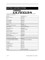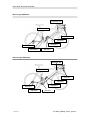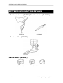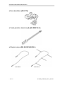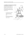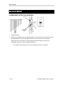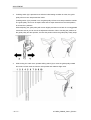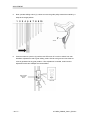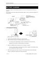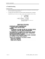
1
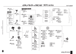
DM0001A000 6770 Series Dealer’s Manual 6770Di2_DMdraft_Ver3.2_EN.doc INTRODUCTION ......................................................................................................................4 TO ENSURE SAFETY ..............................................................................................................5 ELECTRIC SHIFTING SYSTEM .............................................................................................16 SYSTEM CONFIGURATION DETAILS....................................................................................18 SPECIFICATIONS ..................................................................................................................23 INSTALLATION.......................................................................................................................26 ■ Installation of the dual control lever...............................................................................26 ■ Installation of the brake cables .....................................................................................27 ■ Installation of the front derailleur...................................................................................29 ■ Installation of the rear derailleur....................................................................................32 ■ Installation of the chain.................................................................................................33 GEAR SHIFTING OPERATION...............................................................................................34 CONNECTION OF THE ELECTRIC WIRES............................................................................36 ■ Names and example locations of each part ..................................................................36 ■ Front junction: Connection of junction (A) ...................................................................37 ■ Connection to the Dual control lever .............................................................................37 ■ Installation of the battery mount....................................................................................39 ■ Installation and removal of the battery ..........................................................................41 ■ Rear junction: Connection of junction (B) External type.................................................42 ■ Rear junction: Connection of junction (B) Builtin type...................................................47 ■ Installation of the bottle cage adapter ...........................................................................55 ADJUSTMENT........................................................................................................................56 ■ Adjustment of the rear derailleur...................................................................................56 ■ Adjustment of the front derailleur ..................................................................................61 OTHER FUNCTIONS..............................................................................................................63 ■ Battery charge display function.....................................................................................63 ■ Protection function .......................................................................................................64 MAINTENANCE......................................................................................................................65 ■ Disassembly of the bracket unit and lever unit ..............................................................65 ■ Assembly of the switch unit ..........................................................................................67 ■ Assembly of the bracket unit and lever unit...................................................................69 ■ Replacement of the pulley ............................................................................................71 HANDLING THE BATTERY.....................................................................................................72 ■ Storing the battery........................................................................................................72 ■ Battery life....................................................................................................................73 ■ Guide to charging time .................................................................................................73 2 / 77 6770Di2_DMdraft_Ver3.2_EN.doc ■ Proper use of the battery..............................................................................................73 BATTERY CHARGER .............................................................................................................74 ■ Charging the battery.....................................................................................................74 ■ Troubleshooting ...........................................................................................................75 INTERCHANGEABILITY INFORMATION ................................................................................77 3 / 77 6770Di2_DMdraft_Ver3.2_EN.doc INTRODUCTION INTRODUCTION This Dealers Manual is intended for use by people with specialist knowledge such as bicycle safety engineers and bicycle engineers. If you are unsure about any of the information contained in this manual, never install the components yourself. Instead, contact the place of purchase or a bicycle dealer. This Dealers manual can be viewed online on our website (http://techdocs.shimano.com/techdocs/index.jsp). <Notes when reinstalling and replacing components> When reinstalling or replacing components, be sure to disconnect the battery and wait for 10 seconds or more, and then reconnect the battery. The units in the ULTEGRA Di2 6770 series (electronic gear shifting system) are designed to be recognized individually by the system, and so if this step is not carried out, the components will not operate correctly. For safety, be sure to read this Dealer’s Manual thoroughly before use, and follow it for correct use. The following instructions must be observed at all times in order to prevent personal injury and physical damage to equipment and surroundings. The instructions are classified according to the degree of danger or damage which may occur if the product is used incorrectly. DANGER Failure to follow the instructions will result in death or serious injury. WARNING Failure to follow the instructions could result in death or serious injury. CAUTION Failure to follow the instructions could cause personal injury or physical damage to equipment and surroundings. 4 / 77 6770Di2_DMdraft_Ver3.2_EN.doc TO ENSURE SAFETY TO ENSURE SAFETY DANGER Be sure to observe the following in order to avoid burns or other injury from fluid leakages, overheating, fire or explosions. <SMBTR1: Battery> Do not use anything other than the special If any nonspecified items are used, fire, charger to charge the battery. overheating or leakages may occur. Do not heat the battery or throw it into fire. If this is not observed, fire or bursting may occur. Do not leave the battery in places which may If this is not observed, leakages, overheating exceed 60°C in temperature, such as places or bursting may cause fire, burns or other which are exposed to direct sunlight inside injury to occur. vehicles on hot days or near stoves. Do not disassemble or modify the battery or apply solder directly to the battery terminals. Do not connect the (+) and () terminals with If this is not observed, shortcircuits, metallic objects. Do not carry or store the overheating, burns or other injury may occur. battery together with metallic objects such as necklaces or hairpins. If any liquid leaking from the battery gets into If this is not done, blindness may occur. the eyes, immediately wash the affected area with clean water without rubbing the eyes, and then seek medical advice. 5 / 77 6770Di2_DMdraft_Ver3.2_EN.doc TO ENSURE SAFETY <SMBCR1: Battery Charger/SMBCC1: Battery Charger Cord > Do not get the charger wet or use it while it is If this is not observed, problems with wet, and do not touch or hold it with wet operation or electric shocks may occur. hands. Do not cover the charger with a cloth or If this is not observed, heat may build up and similar while it is in use. the case may become deformed, or fire or overheating may occur. Do not disassemble or modify the charger. If this is not observed, electric shocks or injury may occur. Use the charger at the specified power supply If a power supply voltage other than that voltage only. specified is used, fire, explosions, smoke, overheating, electric shocks or burns may occur. Do not touch metallic parts of the charger or If lightning strikes, electric shocks may occur. the AC adapter if there is a lighting storm. WARNING · This Dealer Manual is for use with the ULTEGRA 6770 series (electronic gear shifting system) only. For any information regarding the ULTEGRA 6700 series which does not appear in this manual, refer to the Service Instructions included with each component. · When the shifting switch is operated, the motor which drives the front derailleur will operate without stopping at the shifting lever position. Always be sure to disconnect the battery before carrying out installation, otherwise your fingers may become stuck. · When installing components, be sure to follow the instructions which are given in the dealer’s manual. It is recommended that you use only genuine Shimano parts at this time. In addition, if parts such as bolts and nuts become loose or damaged, the bicycle may suddenly fall over and serious injury may occur as a result. · When installing components, be sure to follow the instructions which are given in the dealer’s manual. If adjustments are not carried out correctly, problems may occur such as the chain coming off, and the bicycle may suddenly fall over and serious injury may occur as a result. · After reading this Dealer Manual thoroughly, keep it in a safe place for later reference. 6 / 77 6770Di2_DMdraft_Ver3.2_EN.doc TO ENSURE SAFETY <SMBTR1: Battery> If charging is not complete after 1.5 hours of If this is not observed, fire, bursting or charging time has elapsed, stop the charging. overheating may occur. Do not place the battery into fresh water or sea water, and do not allow the battery terminals to get wet. The operating temperature ranges for the If the battery is used or stored in temperatures battery are given below. Do not use the which are outside these ranges, fire, injury or battery in temperatures outside these ranges. problems with operation may occur. 1. During discharge: 10°C 50°C 2. During charging: 0°C 45°C Do not use the battery if it has any noticeable If this is not observed, bursting, overheating scratching or other external damage. or problems with operation may occur. Do not subject the battery to strong shocks or throw it. Do not use the battery if leakages, discoloration, deformation or any other abnormalities occur. If any leaked fluid gets on your skin or The leaked fluid may damage the skin. clothes, wash it off immediately with clean water. Do not use or place the battery at or near If this is not observed, sparking, bursting, fire sources of fire. or electric shocks may result. Do not recharge the battery in places which have high humidity or outdoors. Do not insert or remove the plugs while they are wet. If the insides of the plugs are wet, dry them thoroughly before inserting them. 7 / 77 6770Di2_DMdraft_Ver3.2_EN.doc TO ENSURE SAFETY <SMBCR1: Battery Charger/SMBCC1: Battery Charger Cord> Be sure to hold the power cable by the power If you do not hold the power cable by the plug when connecting and disconnecting the power plug, fire or electric shocks may occur. power plug from the electrical outlet. * If heat or acridsmelling smoke is coming out from the power plug. * There may be a bad connection inside the power plug. Do not overload the electrical outlet with If the electrical outlet is overloaded by appliances beyond its rated capacity, and use connecting too many appliances using only a 100 – 240 V AC electrical outlet. adapters, overheating resulting in fire may occur. Do not damage the power cord or power plug. If they are used while damaged, fire, electric (Do not damage, process, forcibly bend, twist shocks or shortcircuits may occur. or pull them, bring them near hot objects, place heavy objects on them or bundle them tightly together.) Do not use the charger with If this is not observed, they may damage the commerciallyavailable electrical transformers charger. designed for overseas use. Always be sure to insert the power plug as far If this is not observed, fire may occur. as it will go. <FC6700: Front Chainwheel> · The two left crank arm mounting bolts should be tightened alternately in stages rather than each bolt being fully tightened all at once. Use a torque wrench to check that the final tightening torques are within the range of 12 14 N∙m. Furthermore, after riding approximately 100 km (60 miles), use a torque wrench to recheck the tightening torques. It is also important to periodically check the tightening torques. If the tightening torques are too weak or if the mounting bolts are not tightened alternately in stages, the right crank arm may come off and the bicycle may fall over, and serious injury may occur as a result. · If the inner cover is not correctly installed, corrosion of the axle may occur, and this may damage the axle and the bicycle may fall over, and serious injury may occur as a result. · Before riding the bicycle, check the crank arms thoroughly to see if they contain any cracks. If the crank arms are cracked, they may break and you may fall off the bicycle. 8 / 77 6770Di2_DMdraft_Ver3.2_EN.doc TO ENSURE SAFETY <CN6701: 10speed Chain for Road Riding> · The frequency of maintenance will vary depending on riding conditions. Periodically clean the chain using an appropriate chain cleaner. Do not use alkaline or acidic cleaning agents for removing rust under any circumstances. If such cleaning agents are used, they may damage the chain and serious injury may result. · This chain has a differentlyshaped forward and reverse in order to improve Forward (outer side) high gear shifting performance. In order The side with the marks shown in the illustration is the forward side(outer side). to obtain the performance for which it is designed, it must be installed so that it Reverse (inner side) faces in the correct direction. If it is installed so that it is facing in the opposite direction, it may come off, and the bicycle may suddenly fall over and serious injury may occur as a result. · Narrowtype chains must always be connected using reinforced connecting pins. · Be careful not to let the cuffs of your clothing get caught in the chain while riding the bicycle. If this is not done, you may fall off the bicycle. · If the chain is connected by using connecting pins other than reinforced connecting pins, or by using reinforced connecting pins or tools which are not suitable for the chain, the connecting force provided maybe insufficient, and the chain may break or fly off. Chain Reinforced connecting pin Tool CN7901 / 6701 / 5701 /4601 Grooved (3) TLCN32/33 10speed compatible supernarrow chain · TLCN23 Grooved (2) TLCN27 After connecting the chain, be sure to feel the connection with your fingers to check that both ends of the connecting pin and the surfaces of the links are flush with each other. (The opposite end of the pin which has been broken off should feel as though it is projecting very slightly.) 9 / 77 6770Di2_DMdraft_Ver3.2_EN.doc TO ENSURE SAFETY · If the length of the chain needs to be readjusted for reasons such as changes to the sprocket configuration, cut the chain at a place which is not connected by means of an reinforced connecting pin. If you cut the chain at a place which has been connected using an reinforced connecting pin, it will damage the chain. Reinforced connecting pin Link pin · Link pin Use a TLCN41 chain wear indicator (Y12152000) or a similar tool to check if the chain has become stretched or damaged. If the chain has become stretched or damaged, it may break and the bicycle may fall over, so the chain should be replaced. · When readjusting the length of the chain, be sure to insert the reinforced connecting pin from the same side as the chain cutter was inserted (the same direction as when the chain was cut). · Be careful not to let the cuffs of your clothes get caught in the chain while riding, otherwise you may fall off the bicycle. CAUTION <SMBCR1: Battery Charger/SMBCC1: Battery Charger Cord> · Disconnect the power plug from the electrical outlet before cleaning. <SMBTR1: Lithium Ion Battery> · Do not disassemble or break the battery. If this is not observed, there is the danger that fire or burns may result. · Do not heat the battery to temperatures which exceed 60°C (140°F). In addition, do not put the battery into fire. Follow the instructions provided by the battery’s manufacturer. · Store the battery in a safe place away from the reach of infants and pets. 10 / 77 6770Di2_DMdraft_Ver3.2_EN.doc TO ENSURE SAFETY NOTE · Be sure to attach dummy plugs to any unused terminals. · Be careful not to let water get into the terminals. · The units are designed to be fully waterproof to withstand wet weather riding conditions. However, do not deliberately place them into water. · Always be sure to use the TLEW02 special tool to remove the electric wires. · If gear shifting operations cannot be carried out smoothly, clean the front and rear derailleurs and lubricate any moving parts. · Periodically wash the chainrings and sprockets with neutral detergent and then lubricate them. In addition, cleaning the chain with neutral detergent and then lubricating it will also help to extend the life of the chainrings and sprockets and the chain. · If the chain keeps skipping, ask the place of purchase to replace the sprockets and/or the chain. · Do not use thinner or other solvents to clean any of the components. Such substances may damage the surfaces. · Do not clean the bicycle in a highpressure car wash. If water gets into any of the components, operating problems or rusting may result. · Do not disassemble, otherwise operating problems will result. · The motors of the front derailleur and the rear derailleur cannot be repaired. · Handle the components carefully, and avoid subjecting them to any strong shocks. · Contact the place of purchase for updates of the component software. The most uptodate information is available on the Shimano website. · Contact Shimano for information regarding the shipment of the battery charger to South Korea and Malaysia. · Natural wear and deterioration which occurs as a result of normal use is not covered by warranty. 11 / 77 6770Di2_DMdraft_Ver3.2_EN.doc TO ENSURE SAFETY <SMBCR1: Battery Charger/SMBCC1: Battery Charger Cord> · If not using the battery for long periods, remove it and store it away in a safe place. · Used batteries should be disposed of in accordance with local waste regulations. Alternatively, ask the place of purchase or a bicycle dealer for disposal. · This appliance is not intended for use by persons (including children) with reduced physical, sensory or mental capabilities, or lack of experience and knowledge, unless they have been given supervision or instruction concerning use of the appliance by a person responsible for their safety. · Do not let children play near these items. Information on disposal in countries other than the European Union This symbol is only applicable within the EU. Used electrical items (battery chargers and battery charger cords) should be disposed of in accordance with local laws and regulations, or ask the place of purchase or a bicycle dealer for disposal. <SMBTR1: Battery> · The battery is uncharged at the time of purchase. Before riding, be sure to charge the battery until it is fully charged. · When storing the battery away, remove the battery from the bicycle and install the terminal cover first. · If the battery is stored away while the battery charge is 50% or higher (the indictor is lit green), the battery will last longer. It is recommended that you check the condition of the battery about once every half a year. · If the battery is stored in cold locations, the performance of the battery may drop and the length of time that it can be used may become shortened. · The battery is a consumable item. The battery will gradually lose its capacity for charging after repeated use and after time has passed. If the length of time that the battery can be used becomes extremely short, it has probably reached the end of its life, and so you will need to purchase a new battery. · The life of the battery will vary depending on factors such as the storage method, the usage conditions, the surrounding environment and the characteristics of the individual battery pack. 12 / 77 6770Di2_DMdraft_Ver3.2_EN.doc TO ENSURE SAFETY · The charging time is approximately 1.5 hours. (Note that the actual time will vary depending on the amount of charge remaining in the battery.) · If the battery feels difficult to insert or remove, apply specified grease (DURAACE grease) to the part that touches the Oring at the side. · For the DURAACE (7970), the bicycle can be ridden for approximately 1000 km on a full charge. For the ULTEGRA (6770), the riding distance will be shorter. (Approximately 30% less according to tests carried out by Shimano.) · Charging can be carried out at any time regardless of the amount of charge remaining. Always be sure to use the special battery charger to charge the battery until it is fully recharged. · If the battery has become fully spent, charge it as soon as possible. If you leave the battery without charging it, it will cause the battery to deteriorate. · If you will not be riding the bicycle for a long period, remove the battery from the bicycle and recharge it periodically. In addition, take care not to let the battery become fully spent. Information on disposal in countries other than the European Union This symbol is only applicable within the EU. Used batteries should be disposed of in accordance with local laws and regulations, or ask the place of purchase or a bicycle dealer for disposal. <EWSD50/EWSD50I: Electric Wires/SMEWC2: Electric Wire Covers> · Secure the electric wires with cable ties so that they do not interfere with the chainrings, sprockets and tires. · The strength of the adhesive is fairly weak, to prevent the paint on the frame from being peeled off at the same time when removing the electric wire cover for reasons such as replacing the electric wires. If the electric wire cover is peeled off, replace it with a new one. When removing the electric wire cover, do not peel it off too vigorously. If this is not observed, the paint on the frame will peel off too. · Do not remove the wire holders which are attached to the builtin type electric wires (EWSD50I). The wire holders prevent the electric wires from moving inside the frame. 13 / 77 6770Di2_DMdraft_Ver3.2_EN.doc TO ENSURE SAFETY <ST6770: Dual Control Lever> · Dummy plugs are installed at the time of shipment from the factory. Do not remove them except when necessary. · Be sure to rotate the front chainwheel when carrying out any lever operations which are related to gear shifting. · When routing the electric wires, take care to ensure that they do not interfere with the brake levers. <RD6770: Rear Derailleur> · Always be sure to adjust the top adjustment bolt and the low adjustment bolt according to the instructions given in the adjustment section. If these bolts are not adjusted, the chain may become clamped between the spokes and the large sprocket and the wheel may lock, or the chain may slip onto the small sprocket. · If the amount of looseness in the links is so great that adjustment is not possible, you should replace the derailleur. · Periodically clean the derailleur and lubricate all moving parts and pulleys. · If gear shifting adjustments cannot be carried out, check the degree of parallel of the rear dropouts. · If there is a large amount of play in the pulleys which causes worrying noise while riding, replace the pulleys. · The tension pulley has an arrow on it to indicate the direction of rotation. Install the tension pulley so that the arrow is pointing clockwise when looking at the pulley from the outside. 14 / 77 6770Di2_DMdraft_Ver3.2_EN.doc TO ENSURE SAFETY <CN6701: 10speed Chain for Road Riding> · As illustrated in Fig. A, we strongly recommend to set the connecting pin in the hole of the outer link on the front side in the direction of travel. The chain’s level of strength is enhanced compared to the method in Fig. B. Chain’s direction of Inner link Outer link Connecting pin Inner link Outer link Connecting pin · Place the chain into the chain cutting tool as shown in the illustration. If the chain is set incorrectly into the chaincutting tool, it will break the positioning plate. 15 / 77 6770Di2_DMdraft_Ver3.2_EN.doc ELECTRIC SHIFTING SYSTEM In order to obtain the optimum performance, it is recommended that you use the following combination of components. Series ULTEGRA 6770 Dual control lever ST6770* Tool TLEWC2 Front derailleur FD6770* Band adapter SMAD67 Rear derailleur RD6770* Chain CN6701 Front junction: Junction (A) SMEW67AE* Electric wires EWSD50*/EWSD50I* Electric wire cover SMEWC2* Grommets SMGM01*/GM02* Lithium ion battery SMBTR1* Battery charger SMBCR1* Battery charger (SMBCR1) cord SMBCC1* Battery mount SMBMR1* Bottle cage adapter SMBA01 Rear junction: Junction (B) SMJC41* (builtin type)/SMJC40* (external type) Etube Project (system checker) SMPCE1 Front chainwheel (bottom bracket) FC6700/FC6750(SMBB6700) Front hub HB6700 Freehub FH6700 Cassette sprocket CS6700 Caliper brakes BR6700 Cantilever brakes BRCX70 Wheels WH6700 Pedals PD6700C/PD6700 * These components are part of the ULTEGRA 6770 series (electronic gear shifting system). 16 / 77 6770Di2_DMdraft_Ver3.2_EN.doc ELECTRIC SHIFTING SYSTEM Builtin type (SMJC41) SMEW67AE FD6770 ST6770 SMBTR1 SMBMR1 RD6770 EWSD50I SMJC41 External type (SMJC40) SMEW67AE FD6770 ST6770 SMBTR1 RD6770 EWSD50 17 / 77 SMBMR1 SMJC40 6770Di2_DMdraft_Ver3.2_EN.doc SYSTEM CONFIGURATION DETAILS SYSTEM CONFIGURATION DETAILS ■ Dual control lever (ST6770)/ Electric wire tool (TLEW02) (ST6770) (TLEW02) ■ Front derailleur (FD6770) ■ Band adapter (SMAD67) (SMAD67L) 18 / 77 (SMAD67M) 6770Di2_DMdraft_Ver3.2_EN.doc SYSTEM CONFIGURATION DETAILS ■ Rear derailleur (RD6770) ■ Front junction: Junction (A) (SMEW67AE) ■ Electric wires (EWSD50/EWSD50I) (EWSD50) 19 / 77 (EWSD50I) 6770Di2_DMdraft_Ver3.2_EN.doc SYSTEM CONFIGURATION DETAILS ■ Electric wire cover (SMEWC2) ■ Frame grommets (SMGM01/SMGM02) ■ Lithium ion battery (SMBTR1) Accessories · Terminal cover ■ Battery charger (SMBCR1) ■ Battery charger cord (SMBCC1) 20 / 77 6770Di2_DMdraft_Ver3.2_EN.doc SYSTEM CONFIGURATION DETAILS ■ Battery mount (SMBMR1) (SMBMR1I) Accessories · Cable tie (x1) · Low head M4 bolt (x1) · Spacer (x3) (SMBMR1L) Accessories · Cable tie (x1) · Low head M4 bolt (x1) (SMBMR1S) Accessories · M4 bolt (x2) ■ Bottle cage adapter (SMBA01) 21 / 77 6770Di2_DMdraft_Ver3.2_EN.doc SYSTEM CONFIGURATION DETAILS ■ Rear junction: Junction (B) Builtin type (SMJC41)/ External type (SMJC40) (SMJC41) (SMJC40) ■ Etube Project: System checker (SMPCE1) Accessories · PClink cable (x2) 2m · USB cable (x1) 50cm 22 / 77 6770Di2_DMdraft_Ver3.2_EN.doc SPECIFICATIONS SPECIFICATIONS ■ Front derailleur Type Brazedon Band type type Model number Band adapter (installation band diameter) Number of larger chainring teeth FD6770F - FD6770L FD6770M FD6770S SMAD67L SMAD67M SMAD67MS (34.9 mm) (31.8 mm) (28.6 mm) 50 56 T Difference in number of larger and smaller 16T or less chainring teeth Chainstay angle (α) 61° 66° Chain line 44.45mm ■ Rear derailleur Type SS Total capacity 33T Maximum no. of largest 28T sprocket teeth Minimum no. of largest 23T sprocket teeth Maximum no. of smallest 12T sprocket teeth Minimum no. of smallest 11T sprocket teeth Difference in number of 16T or less teeth from front 23 / 77 6770Di2_DMdraft_Ver3.2_EN.doc SPECIFICATIONS ■ Battery Battery unit Lithium ion Nominal capacity 530 mAh Weight Standard 71 g Operating temperature During discharge: 10°C 50°C range During charging: 0°C 45°C Storage temperature 20 60 °C range Nominal voltage 7.4 V ■ Battery charger Input 100 240 V AC, 50/60 Hz Output 8.4 V DC, 0.55 A Dimensions Approx. 100 mm (W) x 30 mm (H) x 72 mm (D) Weight Approx. 110 g Operating temperature 0 45 °C Storage temperature 20 60 °C 24 / 77 6770Di2_DMdraft_Ver3.2_EN.doc SPECIFICATIONS 25 / 77 6770Di2_DMdraft_Ver3.2_EN.doc INSTALLATION INSTALLATION ■ Installation of the dual control lever Open up the bracket cover from the front, and then use a 5 mm Allen key to tighten the mounting nut in order to secure the lever unit. Bracket cover 5mm Allen key Tightening torque: 6 8 N・m {52 69 in. lbs.} When installing the components to carbon frame/handle bar surfaces, verify with the manufacturer of the carbon frame/parts for their recommendation on tightening torque in order to prevent over tightening that can cause damage to the carbon material and/or under tightening that can cause lack of fixing strength for the components. 26 / 77 6770Di2_DMdraft_Ver3.2_EN.doc INSTALLATION ■ Installation of the brake cables Cables used Inner cable ..1.6 mm dia. SLR outer casing...5 mm dia. Use cables which are long enough so that they still have some slack even when the handlebars are turned as far as they will go to the left and to the right. 1. Gently pull the brake lever. 2. Pass the inner cable through from directly in front, set the inner cable end into the cable hook, and then install the outer casing from the opposite side. Outer casing Cable hook Inner cable end 27 / 77 6770Di2_DMdraft_Ver3.2_EN.doc INSTALLATION The lever stroke can be smoothly adjusted using the bolt on the top of the bracket unit. Check the lever operation while adjusting. 28 / 77 6770Di2_DMdraft_Ver3.2_EN.doc INSTALLATION ■ Installation of the front derailleur 1. Install the front derailleur to the frame. When installing a brazedon type If installing the front derailleur to a brazedon type frame, a protector must be attached to the seat tube. Always be sure to install the protector in order to prevent damage to the frame from the pressure applied by the support bolt of the front derailleur. Installation of the protector Check the position where the support bolt directly touches the frame when the support bolt of the front derailleur is being adjusted, and attach the protector in that position. In addition, avoid positioning the duct tape that attaches the protector to the seat tube in the location where the support bolt directly touches the frame. Support bolt * Protectors with a curved adhesion surface and a flat adhesion surface exist as shown in the illustration, so use whichever type matches the shape of the frame. 29 / 77 Duct tape 6770Di2_DMdraft_Ver3.2_EN.doc INSTALLATION When installing a band type * If using the band adapter (SMAD67), a support bolt will be necessary. A protector and a mounting washer will not be needed. Use the SMAD67 in combination with the FD6770. The SMAD11/15 cannot be installed. Tightening torque: Band adapter 5 7 N・m {43 60 in. lbs.} Support bolt When installing the components to carbon frame/handle bar surfaces, verify with the manufacturer of the carbon frame/parts for their recommendation on tightening torque in order to prevent over tightening that can cause damage to the carbon material and/or under tightening that can cause lack of fixing strength for the components. 2. Adjust so that there is a clearance of 1 3 mm between the chain guide outer plate and the large chainring. Clearance 1 3 mm Tightening torque: 5 7 N・m {43 60 in. lbs.} Chain guide outer plate 30 / 77 6770Di2_DMdraft_Ver3.2_EN.doc INSTALLATION 3. Use a 5 mm Allen key to secure the chain guide outer plate so that the flat part of the plate is directly above the large chainring and so that the rear edge of the chain guide is within 0.5 – 1.0 mm from the front edge of the chain guide. Front chainwheel (large chainring) Chain guide 0.5 1.0mm 4. Use a 2 mm Allen key to turn the support bolt in order to adjust the position of the front derailleur so that the flat part of the chain guide outer plate is directly above and parallel to the large chainring. 31 / 77 6770Di2_DMdraft_Ver3.2_EN.doc INSTALLATION ■ Installation of the rear derailleur When installing the rear derailleur, make sure that the Btension adjustment bolt does not touch the dropout tab and cause it to bend. Btension adjustment bolt Dropout tab Pulley cage 5mm Allen key Bracket tightening torque: 8 10 N・m {70 86 in. lbs.} 32 / 77 6770Di2_DMdraft_Ver3.2_EN.doc INSTALLATION ■ Installation of the chain Note: This 10speed chain for road riding has a differentlyshaped forward side and reverse side in order to improve high gear shifting performance. Forward (outer side) The side with the marks shown in the illustration is the forward side (outer side). Reverse (inner side) Chain length Smallest sprocket Larger chainring Chain Guide pulley Tension pulley * If the largest sprocket is 28T or more Add 2 links while the chain is on the larger chainring and the largest sprocket. Largest sprocket Chain 33 / 77 Larger chainring + 2 links 6770Di2_DMdraft_Ver3.2_EN.doc GEAR SHIFTING OPERATION GEAR SHIFTING OPERATION ■ Dual control lever (ST6770) Operating the rear shifting switches (initial settings) <Shifting switch (X)> The chain moves from a smaller sprocket to a larger sprocket each time the switch is operated. <Shifting switch (Y)> The chain moves from a larger sprocket to a smaller sprocket each time the switch is operated. Shifting switch (X) 34 / 77 Shifting switch (Y) 6770Di2_DMdraft_Ver3.2_EN.doc GEAR SHIFTING OPERATION Operating the front shifting switches (initial settings) <Shifting switch (X)> The chain moves from the smaller chainring to the larger chainring. <Shifting switch (Y)> The chain moves from the larger chainring to the smaller chainring. Shifting switch (X) Shifting switch (Y) If the chain falls off on the inside, keep pressing shifting switch (X) for 1 second or more to move the front derailleur to the outermost position, and then keep it pressed for 10 seconds in order to reset the chain. There is a function using the SMPCE1 for changing between shift up and shift down operations for shifting switches (X) and (Y) and the rear shifting switch and front shifting switch. * For details on changing the shifting switches, refer to the help screens for Etube Project (PC application). 35 / 77 6770Di2_DMdraft_Ver3.2_EN.doc CONNECTION OF THE ELECTRIC WIRES CONNECTION OF THE ELECTRIC WIRES ■ Names and example locations of each part Builtin type(SMJC41) SMEW67AE EWSD50I SMJC41 External type(SMJC40) SMEW67AE SMJC40 36 / 77 EWSD50 6770Di2_DMdraft_Ver3.2_EN.doc CONNECTION OF THE ELECTRIC WIRES ■ Front junction: Connection of junction (A) When routing the SMEW67AE, allow enough looseness in the cable so that the ST6770 installation position can be adjusted and so that the handlebars can be turned fully to the left and right. When routing the electric wires, they can be wrapped around the handlebars when wrapping the handlebar tape. (Sample connection diagram for ST6770 and SMEW67AE) ■ Connection to the Dual control lever 1. Use the TLEW02 special tool to connect to the ST6770. Set so that the projection on the connector is aligned with the groove on the narrow end. 37 / 77 6770Di2_DMdraft_Ver3.2_EN.doc CONNECTION OF THE ELECTRIC WIRES 2. Open up the bracket cover and lift up the connector cover. Use the TLEW02 to connect the connector of the electric wire to the terminal on the lever side. Be sure to push them together until they connect with a click. Either the top or bottom terminal can be used. 3. The remaining terminal can be used for an additional satellite switch or the SMPCE1. 4. Use the accessory cable ties to secure junction (A) to the outer casing of the brake cable. 38 / 77 6770Di2_DMdraft_Ver3.2_EN.doc CONNECTION OF THE ELECTRIC WIRES ■ Installation of the battery mount 1. Set the battery mount into position. Use the bottle cage fixing bolt to provisionally install the battery mount to the bottom of the bottle cage. Use the bolts which are included with the bottle cage to secure the SMBMR1L (long type). Refer to the Service Instructions for the bottle cage for details on the tightening torques. Use the included M4 bolts to secure the SMBMR1S (short type). Tightening torque: 1.2 1.5 N・m {10.4 13 in. lbs.} 2. Leave a space of 108 mm or more at the end of the battery mount. Check that the battery can be inserted and removed while the bottle cage is installed. 108 mm Tightening torque: 1.2 1.5 N・m {10.4 13 in. lbs.} 39 / 77 6770Di2_DMdraft_Ver3.2_EN.doc CONNECTION OF THE ELECTRIC WIRES 3. Tighten the bolt of the bottle cage to secure the battery mount. For the SMBMR1L (long type), use the accessory cable ties to secure the battery mount to the frame. Cable tie * If there is a mounting boss on the frame, the battery mount can be secured to the frame with a bolt. 2mm Allen key Battery mount fixing bolt (M4 x 15mm) Tightening torque: 1.2 1.5 N・m {11 13 in. lbs.} 40 / 77 6770Di2_DMdraft_Ver3.2_EN.doc CONNECTION OF THE ELECTRIC WIRES ■ Installation and removal of the battery 1. Open the clamp, and then install the battery so that it follows the groove in the battery mount. Close the clamp until it clicks into place. 2. Open the clamp, pull out the battery slightly, and then press the button to fully remove the battery. Clearance 41 / 77 6770Di2_DMdraft_Ver3.2_EN.doc CONNECTION OF THE ELECTRIC WIRES ■ Rear junction: Connection of junction (B) External type (SMJC40) 1. Connect the electric wires to junction (A) and junction (B). Be sure to push them together until they connect with a click. Junction (A) Junction (B) 2. Connect the electric wires to the front derailleur, the rear derailleur and the battery mount. At front derailleur At rear derailleur At battery mount 42 / 77 6770Di2_DMdraft_Ver3.2_EN.doc CONNECTION OF THE ELECTRIC WIRES 3. Provisionally secure the electric wire along the frame with tape, and then connect it to junction (B). * When routing the electric wire to the rear derailleur, be sure to install it to the bottom of the chainstay to avoid any interference between the cable and the chain. * Wind any excess length of electric wire inside junction (B) to adjust the length. Example of adjusting junction (B) length 4. Once the electric wires have been routed, secure junction (B) underneath the bottom bracket shell. Junction (B) fixing bolt (10.5mm or 15mm) (3mm Allen key) Tightening torque: 1.5 2 N・m {13 18 in. lbs.} 43 / 77 6770Di2_DMdraft_Ver3.2_EN.doc CONNECTION OF THE ELECTRIC WIRES 5. Next, install the electric wire cover to the frame. In order to make sure that the electric wire cover is securely installed, clean the frame with alcohol or some other cleaning agent to remove any grease or other substances before installing the cover. Place the electric wire cover over the electric wires, and then attach it to the frame. 44 / 77 6770Di2_DMdraft_Ver3.2_EN.doc CONNECTION OF THE ELECTRIC WIRES Checking connections After connecting the electric wires to all of the components, install the battery and check the operation. Operate the shifting switches and check that the front derailleur and rear derailleur both operate. Shifting switch (X) Note: * If not installing the chain at this point, be sure to operate shifting switch (X) for the left lever once or more to set the front derailleur to the larger chainring position when installing the chain. After this, be sure to remove the battery. 45 / 77 6770Di2_DMdraft_Ver3.2_EN.doc CONNECTION OF THE ELECTRIC WIRES Disconnection of the electric wires Use the wide end of the TLEW02 special tool to disconnect the electric wires. If you pull too firmly on the connectors, problems with operation may occur. Insert the special tool so that the flat side is facing toward the derailleur, and then tilt it so as to pull out the connector of the electric wire. When disconnecting the electric wire from a lever, face the flat side toward the lever. When disconnecting the connector of junction (A) or junction (B), insert the special tool so that the flat side is facing toward junction. ST6770 FD6770 SMJC40 * RD6770 SMJC41 Run any excess length of electric wire along the handlebar, and use cable ties or similar to secure the electric wire to the handlebar. 46 / 77 6770Di2_DMdraft_Ver3.2_EN.doc CONNECTION OF THE ELECTRIC WIRES ■ Rear junction: Connection of junction (B) Builtin type (SMJC41) 1. First pass the electric wires for junction (A), the battery mount, the front derailleur and the rear derailleur through the holes in the frame into the bottom bracket shell. * The electric wires have a correct way of being inserted. Make sure that you insert them from the direction shown in the illustration. Wire holder 47 / 77 6770Di2_DMdraft_Ver3.2_EN.doc CONNECTION OF THE ELECTRIC WIRES Electric wire for front derailleur Electric wire for rear derailleur Electric wire for junction (A) Electric wire for battery mount Bottom bracket shell 48 / 77 6770Di2_DMdraft_Ver3.2_EN.doc CONNECTION OF THE ELECTRIC WIRES 2. Connect each electric wire to junction (B). Be sure to push them together until they connect with a click. 49 / 77 6770Di2_DMdraft_Ver3.2_EN.doc CONNECTION OF THE ELECTRIC WIRES 3. Connect the electric wires to junction (A), the front derailleur, the rear derailleur and the battery mount. At junction (A) At rear derailleur 50 / 77 At front derailleur At battery mount 6770Di2_DMdraft_Ver3.2_EN.doc CONNECTION OF THE ELECTRIC WIRES Routing junction (B) and the electric wires inside the frame 1. Pass the electric wires for the front derailleur and the rear derailleur through the seat tube and chainstay respectively. 2. Pass the electric wires for junction (A) and the battery mount and junction (B) through the down tube. Check that the screws of the bottom bracket shell do not damage any of the components at this time. 3. Set the electric wires so that only the electric wires for the front derailleur and the rear derailleur are visible inside the bottom bracket shell, and if any extra parts such as wire holders are protruding, push them back inside the frame. For junction (A) For front derailleur 1 2 For battery mount For rear derailleur Junction (B) 3 51 / 77 6770Di2_DMdraft_Ver3.2_EN.doc CONNECTION OF THE ELECTRIC WIRES Assembly of the bottom bracket shell 1. When installing the inner cover to the bottom bracket shell, make sure that the electric wires for the front derailleur and the rear derailleur pass over the top of the inner cover. 2. Install the inner cover to the bottom bracket adapter. Inner cover Adapter Adapter Adapter Inner cover Note: * If using a frame which does not have enough space between the inside of the bottom bracket shell and the inner cover to route the electric wires use an inner cover which is sold separately. Installation of the battery mount 1. Set the electric wire for the battery mount into the groove in the electric wire cover for the battery mount. 2. Place the accessory spacers in between the battery mount and the frame and then secure them by tightening the bolts. * If installing the bottle cage, it is easier to install it at this stage. * Refer to the Service Instructions for the bottle cage for details on the tightening torques. 52 / 77 6770Di2_DMdraft_Ver3.2_EN.doc CONNECTION OF THE ELECTRIC WIRES 3. Use the accessory cable tie to secure the battery mount to the frame. Spacers Cable tie * If there is a mounting boss on the frame, the battery mount can be secured to the frame with a bolt. 2mm Allen key Battery mount fixing bolt (M4 x 15mm) Tightening torque: 1.2 1.5 N・m {11 13 in. lbs.} 53 / 77 6770Di2_DMdraft_Ver3.2_EN.doc CONNECTION OF THE ELECTRIC WIRES Installation of the grommets Install grommets in appropriate positions for the electric wires by inserting the bottoms into the holes in the frame and then pushing the tops to fit them into place. At junction (A) Closed 54 / 77 Open At rear derailleur At front derailleur 6770Di2_DMdraft_Ver3.2_EN.doc CONNECTION OF THE ELECTRIC WIRES ■ Installation of the bottle cage adapter 3mm Allen key If the bottle cage which is installed to the 10mm seat tube interferes with the battery, move the position of the bottle cage upward. The installation position for the bottle cage can be moved upward by a minimum of 32 mm and a maximum of 50 mm from the original installation position. 10mm Spacers * If it interferes with the installation mounting boss for the front derailleur, use the accessory 15mm spacer. * Refer to the Service Instructions Tightening torque: 3 N・m {26 in. lbs.} for the bottle cage for details on the tightening torques. 55 / 77 6770Di2_DMdraft_Ver3.2_EN.doc ADJUSTMENT ADJUSTMENT ■ Adjustment of the rear derailleur Junction (A) Illuminates (red) Rear derailleur adjustment button 1. Install the battery. 2. Shift the rear derailleur to the 5th sprocket position. Press the button at the junction (A) of the SMEW67AE until the red LED illuminates in order to switch to rear derailleur adjustment mode. Note that if you keep pressing the button after the red LED has illuminated, protection recovery operation will begin. * For details on protection function, refer to ‘Protection function’ on page 64 56 / 77 6770Di2_DMdraft_Ver3.2_EN.doc ADJUSTMENT 3. If shifting switch (X) is pressed once while the initial setting condition is active, the guide pulley will move one step toward the inside. If shifting switch (Y) is pressed once, the guide pulley will move one step toward the outside. The guide pulley can move 15 steps inward and 15 steps outward from the initial position, for a total of 31 positions. When adjusting, the guide pulley will overrun slightly and then move back in an exaggerated movement so that you can check the adjustment direction. When checking the positions of the guide pulley and the sprocket, check at the position where the guide pulley finally stops. X Y 4. While turning the crank arms, operate shifting switch (X) to move the guide pulley toward the inside until the chain touches the 4th sprocket and makes a slight noise. 57 / 77 6770Di2_DMdraft_Ver3.2_EN.doc ADJUSTMENT 5. Next, operate shifting switch (Y) 4 times to move the guide pulley toward the outside by 4 steps to the target position. 4 times 4 steps 6. Press the button at junction (A) until the red LED turns off in order to switch from rear derailleur adjustment mode to gear shifting mode. Shift to each gear and check that no noise is generated at any gear position. If fine adjustment is needed, switch back to adjustment mode and readjust the rear derailleur. Rear derailleur adjustment button Turned off 58 / 77 6770Di2_DMdraft_Ver3.2_EN.doc ADJUSTMENT 7. Next, carry out the adjustments for the low adjustment bolt and top adjustment bolt. <Low adjustment> Shift the rear derailleur to the largest sprocket, and then tighten the low adjustment bolt until it touches against the stopper. If it is tightened too much, the motor will detect a problem and gear shifting operation will not be carried out correctly. Symptom · Does not shift to low gear. · Noise does not stop. · Battery charge disappears quickly .(load is being placed on the motor.) 2mm Allen key Low adjustment bolt <Top adjustment> Shift the rear derailleur to the smallest sprocket, and then tighten the top adjustment bolt until it touches the stopper at the position where the rear derailleur finally stopped. From this position, turn the top adjustment bolt counterclockwise one turn so that an overstroke allowance can always be maintained. 2mm Allen key Top adjustment bolt 59 / 77 6770Di2_DMdraft_Ver3.2_EN.doc ADJUSTMENT By shifting from a large sprocket to a smaller sprocket, the rear derailleur will move toward the outside by the overstroke allowance and then move back. 8. Adjust the Btension adjustment bolt. Set the chain onto the smaller chainring and the largest sprocket, and then turn the crank arms backward. Turn the Btension adjustment bolt to adjust so that the guide pulley moves close to the sprocket without obstructing the chain. Next, set the chain onto the smallest sprocket and check in the same way that the guide pulley does not obstruct the chain. Largest sprocket Guide pulley 60 / 77 Smallest sprocket Btension adjustment bolt 6770Di2_DMdraft_Ver3.2_EN.doc ADJUSTMENT ■ Adjustment of the front derailleur Note: * The low adjustment bolt, the top adjustment bolt and the support bolt are close to each other. Make sure that you are using the correct bolt for adjustment. Support bolt Top adjustment bolt Low adjustment bolt <Low adjustment> Set the chain onto the smaller chainring and the largest sprocket. Use a 2 mm Allen key to turn the low adjustment bolt to adjust so that there is a clearance of 0 0.5 mm between the chain and the chain guide inner plate. 0 0.5 mm 61 / 77 6770Di2_DMdraft_Ver3.2_EN.doc ADJUSTMENT <Top adjustment> Next, set the chain onto the larger chainring and the smallest sprocket. Use a 2 mm Allen key to turn the top adjustment bolt to adjust so that there is a clearance of 0.5 1 mm between the chain and the chain guide outer plate. Move the front derailleur and the rear derailleur to all gear positions, and check that the chain guide does not touch the chain. 0.5 1 mm 62 / 77 6770Di2_DMdraft_Ver3.2_EN.doc OTHER FUNCTIONS OTHER FUNCTIONS ■ Battery charge display function Press and hold either shifting switch for 0.5 seconds or more. You can check the amount of battery charge remaining using the battery indicator on junction (A). * When the battery charge is low, first the front derailleur will stop operating, and then the rear derailleur will stop operating. When the battery charge has been fully spent, the derailleurs will be fixed at the last gear shifting position. If the battery indicator is illuminated red, it is recommended that you recharge the battery as soon as possible. 63 / 77 6770Di2_DMdraft_Ver3.2_EN.doc OTHER FUNCTIONS ■ Protection function * Rotate the front chainwheel while restoring operation after the protection function has been activated. If the bicycle receives a strong impact, the protection function operates and the connection between the motor and the link is momentarily severed so that the rear derailleur will no longer operate. This is done in order to protect the system at times such as if the bicycle falls over. If this happens, press the rear derailleur adjustment button on junction (A) of the SMEW67AE for 5 seconds or more. This will restore the connection between the motor and the link and clear the protection function for the rear derailleur. If the connection is not restored, push/pull the cage sideways or move it forward and backward by hand. Operate the shifting switches to check that the connection has been restored. Junction (A) Illuminates (red) Rear derailleur adjustment button Button hold Illuminates down (red) Flashes (red) Protection clear operation Approx. 5 seconds in total Protection cleared When the red LED on junction (A) is illuminated, the rear derailleur cannot shift gears. Keep pressing the rear derailleur adjustment button until the red LED turns off. 64 / 77 6770Di2_DMdraft_Ver3.2_EN.doc MAINTENANCE MAINTENANCE * The illustrations show the rightside lever. ■ Disassembly of the bracket unit and lever unit 1. Use the special tool which is sold separately to remove the stop ring. Align part B of the special tool with the removal direction of the stop ring. Next, set part A onto the stop ring and remove the stop ring. Note: * Special Ering removal tool The stop ring may fly off suddenly during removal, so check that there are no people or objects nearby while removing the stop ring. 65 / 77 6770Di2_DMdraft_Ver3.2_EN.doc MAINTENANCE 2. Insert an Allen key or a similar tool into the hole in the lever stud, and then tap it with a plastic mallet to push out the lever stud. Lever stud 3. Remove the return spring. Return spring 66 / 77 6770Di2_DMdraft_Ver3.2_EN.doc MAINTENANCE 4. Remove the two switch unit fixing screws, and then remove the switches and the switch springs. The bracket unit and the lever unit can then be disassembled. Switch unit fixing screws (#T5 TORX®) TORX is a registered trademark of Camcar LLC. ■ Assembly of the switch unit 1. Check that the buttons are attached to the springs, and then place the switch springs into the holes in the switch unit setting plate. DURAACE Grease (Y04110000) Apply grease Switch springs 67 / 77 6770Di2_DMdraft_Ver3.2_EN.doc MAINTENANCE 2. Place the switch unit against the mounting surface of the switch unit setting plate. 3. Press the switch unit by hand so that the switch springs go into the grooves in the buttons, and then push the shifting switches (X and Y) in as far as they will go. Switch unit Shifting switches (X/Y) 4. Make a gap between the switch unit and the switch unit setting plate and check that the end of the rubber on the switch unit is on the button. 68 / 77 6770Di2_DMdraft_Ver3.2_EN.doc MAINTENANCE 5. Return the switch unit to the setting position for the switch unit setting plate, and while pressing it by hand, operate the shifting switches (X and Y) once more and check that the switches turn on. Install the switch using the switch unit fixing screws. Tightening torque: 0.18 N・m {1.5 in. lbs.} ■ Assembly of the bracket unit and lever unit 1. Assemble the bracket unit and the lever unit, and then attach the return spring. 69 / 77 6770Di2_DMdraft_Ver3.2_EN.doc MAINTENANCE 2. Align with the hole in the stud, and then pressfit the lever stud. * The correct direction for the lever stud is when the stop ring groove is at the top. * Check that the surface of the bracket unit and the top end of the lever stud are flush with each other so that the stop ring will fit into the groove. 3. Use part A of the special tool to install the stop ring. * Operate the shifting switches (X and Y) and check that they turn on, and check that the lever operates smoothly. 70 / 77 6770Di2_DMdraft_Ver3.2_EN.doc MAINTENANCE ■ Replacement of the pulley Guide pulley / tension pulley tightening torque: 2.5 5 N・m {22 44 in. lbs.} 2mm Allen key 71 / 77 6770Di2_DMdraft_Ver3.2_EN.doc HANDLING THE BATTERY HANDLING THE BATTERY The battery is a lithium ion battery. Use the special battery charger (SMBCR1) to recharge the battery. Never use any other battery charger to recharge the battery. If this is not observed, explosions or fire may result. Electrical contacts Do not modify or damage these, otherwise problems with operation will result. Take proper care when handling the battery. ■ Storing the battery When storing the battery away, remove the battery from the system and install the terminal cover first. Terminal cover · If the battery is stored away while the battery charge is 50% or higher (the indictor is lit green), the battery will last longer. It is recommended that you check the condition of the battery about once every half a year. · If the battery is stored in cold locations, the performance of the battery may drop and the length of time that it can be used may become shortened. 72 / 77 6770Di2_DMdraft_Ver3.2_EN.doc HANDLING THE BATTERY ■ Battery life The battery is a consumable item. The battery will gradually lose its capacity for charging · after repeated use and after time has passed. If the length of time that the battery can be used becomes extremely short, it has probably reached the end of its life, and so you will need to purchase a new battery. The life of the battery will vary depending on factors such as the storage method, the usage · conditions, the surrounding environment and the characteristics of the individual battery pack. ■ Guide to charging time The charging time is approximately 1.5 hours. (Note that the actual time will vary depending on the amount of charge remaining in the battery.) ■ Proper use of the battery If the battery feels difficult to insert or remove, apply some specified grease (DURAACE grease). Apply the specified grease to the sides where the Orings touch. Apply grease DURAACE Grease (Y04110000) Note: * For the DURAACE (7970), the bicycle can be ridden for approximately 1000 km on a full charge. For the ULTEGRA (6770), the riding distance will be shorter. (Approximately 30% less according to tests carried out by Shimano.) 73 / 77 6770Di2_DMdraft_Ver3.2_EN.doc BATTERY CHARGER BATTERY CHARGER The battery charger is a special battery charger for use only in recharging Shimano lithium ion batteries. Never insert any other type of battery into the battery charger. If this is not observed, explosions or fire may result. Power cable connector Electrical contacts Do not modify or damage these, otherwise problems with operation will result. Take proper care when handling the battery. Error indicator Flashes when there is an error. Battery charger cord (SMBCC1) <sold separately> Insert into the connector. * Insert securely as far as it will go. Charge indicator Illuminates during charging. ■ Charging the battery Illuminates orange 1. Insert the plug of the battery charger into an electrical outlet. 2. Place the battery securely into the battery charger as far as it will go. * The charging time is approximately 1.5 hours. (Note that the actual time will vary depending on the amount of charge remaining in the battery.) 3. When the CHARGE indicator (orange) turns off, charging is complete. * If the error indicator flashes, it means that there may be a problem with the battery. Refer to the troubleshooting section for details. 4. Disconnect the plug of the battery charger from the electrical outlet, and store the battery charger in a safe place according to the safety instructions. 74 / 77 6770Di2_DMdraft_Ver3.2_EN.doc BATTERY CHARGER ■ Troubleshooting If an error occurs · Remove the battery from the battery charger, disconnect the plug from the electrical outlet, and then repeat the charging operation. · If charging cannot be carried out even after the above steps are taken, the ambient temperature may be too low or too high, or there may be a problem with the battery. If charging is not possible, the error indicator on the battery charger will flash. 75 / 77 6770Di2_DMdraft_Ver3.2_EN.doc BATTERY CHARGER 76 / 77 6770Di2_DMdraft_Ver3.2_EN.doc INTERCHANGEABILITY INFORMATION INTERCHANGEABILITY INFORMATION · The ULTEGRA 6770 series is not interchangeable with the DURAACE 7970 series. 77 / 77 6770Di2_DMdraft_Ver3.2_EN.doc