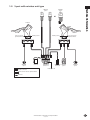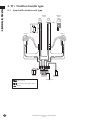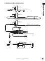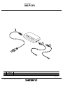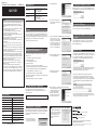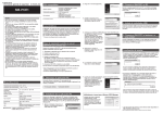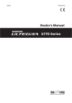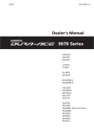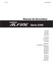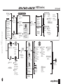
1
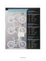
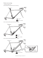
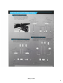
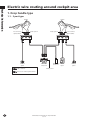
9070 series
Around cockpit area
SW-R610
Remote sprinter
shifter
Junction
for cockpit area
3 port
ST-9070
SW-9071
Remote TT/Time
trial shifter
New 1 button
design
Dual control
lever
SW-R671
SM-EW90-F
Dual control lever
SM-AD90
Band adapter
Electric wire for
external wire routing
2 pcs
11-speed HG CS
11-23T
11-25T
11-28T
12-25T
12-28T
Heart rate monitor
SM-BB9000
BB unit
SM-BB92-41B
Press - Fit type BB
SM-BMR2-L/S/I
SM-BCC1
Battery charger
Cord for SM-BCR1
Battery cage adapter
Electric wire for
built-in type
wire routing
Built-in wire routing
SM-JC41
Junction
Built-in type
SM-BTR2
Battery
Built-in type
SM-BCR2
Cord cover
Battery charger
for SM-BTR2
SM-SPD1
Speed sensor
Caliper brake
Direct mount
WH-9000-C75-TU
75mm deep
Carbon Tubular
Wheel set
WH-9000-C50-TU
50mm deep
Carbon Tubular
Wheel set
CN-9000
BR-9010-F
Direct mount
caliper brake / Front
FC-9000
HOLLOWTECH-II
W/BB cup unit
50-34T 53-39T
52-36T 54-42T
52-38T 55-42T
SM-BCR1
Battery
SM-BA01
SM-EWC2
SM-HRR1
SM-BTR1
Battery mount
EW-SD50-I
4pcs for
SM-JC40/41
BR-9000
CS-9000
Junction
WH-9000-C50-CL
WH-9000-C35-TU
35mm deep
Carbon Tubular
Wheel set
WH-9000-C24-TL
Carbon/Aluminum
Road Tubeless
Wheel set
WH-9000-C35-CL
35mm deep
Carbon/Aluminum
Clincher
Wheel set
50mm deep
Carbon/Aluminum
Clincher
Wheel set
WH-9000-C24-CL
Carbon/Aluminum
Clincher
Wheel set
PD-9000
SPD-SL Pedal
BR-9010-R
Direct mount
caliper brake / Rear
SM-CB90
Cable adjuster
for BR-9010
HB-9000
FH-9000
CP-W020 (10-speed)
CP-W024 (10-speed)
CP-WH23
CP-W184
Spoke protector
BC-9000
Brake cable
1
Line-up Chart
Version 1.4
All information on this page as of Apr. 27th 2012.
ST-9071
Junction
for cockpit area
with wireless unit
5 port
Super narrow
HG chain
for 11-speed
FD-9070-F
EW-SD50
Junction
for cockpit area
with wireless unit
5 port
SM-EW90-F
SM-JC40
Electric wire for
external wire
routing
Cycle computer
Wireless type
SW-R600
RD-9070-SS
EW-SD50
SC-R770
Remote Triathlon
shifter
Current 2 button
design
Remote satellite
shifter
(Climbing shifter)
External wire routing
SM-EW90-A
TT/TRI spec
(2×11-speed)
,0*BSVG
Electric wire routing
< DURA-ACE 9070 series >
Built-in battery mount type (Internal wire routing)
Connector
Hole
Junction (SM-JC41)
External battery mount type (Internal wire routing)
Connector
Hole
Junction (SM-JC41)
External battery mount type (External wire routing)
Connector
Junction (SM-JC40)
20
All information on this page as of Apr. 27th 2012.
Junction
(SM-JC40)
,0*BSVG
Electric wire routing around cockpit area
Technical Information
1. Drop handle type
1-1. 3 port type
ST-9070
Port for remote
sprinter shifter
ST-9070
E-tube port ×2
SW-R610
option
E-tube port ×2
SM-EW90-A
Junction-A
SM-JC40/41 SW-R600
Junction-B
option
E-tube port ×3
E-tube connector
Connector for remote sprinter shifter
22
All information on this page as of Apr. 27th 2012.
Version 1.4
Port for remote
sprinter shifter
SW-R610
option
1-2. 5 port with wireless unit type
SW-R671
option
Technical Information
SW-9071
option
or
ST-9070
ST-9070
Port for remote
sprinter shifter
SW-R610
option
E-tube port ×2
SC-R770
E-tube port ×2
SM-EW90-F
Junction-A
SM-JC40/41 SW-R600
Junction-B
option
Port for remote
sprinter shifter
SW-R610
option
E-tube port ×5
E-tube connector
Connector for remote sprinter shifter
Wireless
All information on this page as of Apr. 27th 2012.
Version 1.4
23
2. TT / Triathlon handle type
Technical Information
2-1. 5 port with wireless unit type
SW-9071
option
SW-R671
option
or
6
18
ST-9071
ST-9071
SC-R770
SM-EW90-F
Junction-A
SM-JC40/41
Junction-B
E-tube port ×5
E-tube connector
Connector for remote sprinter shifter
Wireless
24
All information on this page as of Apr. 27th 2012.
Version 1.4
2. Battery holder and junction
Technical Information
Short size
Battery Holder
SM-BMR2-S (External wire routing)
Long size
Battery Holder
SM-BMR2-I (Internal wire routing)
Long size
Battery Holder
13
30
SM-BMR2-L (External wire routing)
Junction
SM-JC40 (External mount type)
14.3
Junction
SM-JC41 (Built in type)
30
53.6
8
All information on this page as of Apr. 27th 2012.
Version 1.4
7
PC Linkage
SM-PCE1
1
SM
-P
CE
1
2
2
ITEM
NO.
1
2
SHIMANO
CODE NO.
Y7EA02000
Y7EA03000
DESCRIPTION
USB Cable
PC Link Cable
Feb.-2011-3138
© Shimano Inc. I
Specifications are subject to change without notice.
SI-7EA0A-002-00
Technical Service Instructions
SI-7EA0A-002
SM-PCE1
NOTE
2. Click the [Next] button.
Compatible PCs
Operating system
Windows XP 32bit/64bit (SP2 or higher)
Windows Vista 32bit/64bit
Windows 7 32bit/64bit
Required components
.NET Framework 3.5
Other hardware
USB 1.1/2.0
Active Internet connection
Display resolution:
XGA (1024 x 768 dots) or higher
(as of 1 November 2010)
• Do not use outdoors or in environments with high humidity.
• Do not place the SM-PCE1 on dusty floors when using it.
• Place the SM-PCE1 on a stable surface such as a table when
using it.
• Do not place any objects on top of the SM-PCE1 or its cables.
• Do not wrap the cables into bundles.
• Do not hold the SM-PCE1 by the cables when carrying it.
• Do not apply excessive tension to the cables.
• Do not use any USB cable other than the USB cable which is
supplied with the SM-PCE1.
• Connect the SM-PCE1 directly to a computer, without using an
intermediate device such as a USB hub.
• Do not ride the bicycle while the SM-PCE1 and cable are still
connected to it.
• Do not connect two or more of the same units to the same
connection point. If this is not done, the units may not operate
correctly.
• Do not connect or disconnect units again while unit recognition is
in progress or after recognition is complete. If this is not done,
the units may not operate correctly.
Check the procedures which are given in the user's manual for
the PC application when connecting and disconnecting units.
• After connecting the battery and launching the PC application,
be sure to disconnect the SM-PCE1 from the bicycle and then
disconnect and reconnect the battery. If this is not done, the
system may not operate correctly.
• The tightness of the PC link cable will tend to drop after
repeated connections and disconnections. If this happens,
replace the cable.
• Do not wash the SM-PCE1 or wipe it using detergents.
• Do not connect two or more SM-PCE1 units to the same PC at
the same time. If two or more SM-PCE1 units are connected,
they will not operate correctly. In addition, operating errors may
occur at the PC and it may require the PC to be restarted.
When the PC application is run, a “Connect the SM-PCE1.” message
will be displayed, so connect the USB cable of the SM-PCE1 to the PC.
3. If you agree to the terms of the
Software License Agreement, click
the [Yes] button.
The SM-PCE1 can be used to connect a PC to the bicycle (system or
unit), and a PC application (such as Shimano STEPS Manager) can be
used to carry out tasks such as problem diagnosis of single units and
the whole system, updating firmware*, and retrieving logs. For details on
operating the PC, refer to the manual for the PC application.
* Firmware: the software inside each unit
Flow of operation when using the
SM-PCE1 for the first time
After purchasing the SM-PCE1, follow this procedure to prepare the
SM-PCE1 for use.
Download the PC application from the website.
4. If you would like Shimano STEPS Manager to be available for use
by all users of the PC, select
“Anyone who uses this computer
(all users)”. If you would like only
the current user of the PC to be
able to use the application, select
“Only for me”. After making the
selection, click the [Next] button.
5. Select the installation folder and
then click the [Next] button.
Install the USB driver.
• For details, refer to the manual for the PC application.
• The method for displaying the manual for Shimano STEPS Manager
is given in “Displaying the manual for Shimano STEPS Manager”.
5. Connect the SM-PCE1 to the system or to a unit.
6. Installation will begin when you
1. Downloading the PC application
The PC application can be obtained by downloading it from
http://media.shimano.com. You will need the following user ID and
password at this time.
• User ID: shimano
– 20 °C -- 70 °C
Operating/ storage humidity
10 -- 95 % RH/ 10 -- 95 % RH
Rated voltage
5V±5%
Rated power
2.5 W
Interface
USB 2.0 (Full Speed)
Port type
At PC: A type
At SM-PCE1: Mini B type
Dimensions
96.4 x 53.4 x 22 mm
Weight
80 g
LED
During normal operation: Illuminated
During charging: Flashing
Accessories: * PC link cable (x 2) 2 m
* USB cable (x 1) 50 cm
• Password: 2s8m8n3
2. Installing the PC application
After downloading the PC application, run the Installer to install it to the
PC by the following procedure. (The screenshots below show examples
of installing Shimano STEPS Manager to a PC which is running
Windows XP.)
1. Run the Installer. Select the
language in the window which
appears, and then click [OK].
If the same problem occurs even after repeatedly disconnecting and
reconnecting the USB cable, contact the place of purchase or the
nearest bicycle manufacturer in the country of use.
click the [Install] button.
• If the LED on the SM-PCE1 does not illuminate after the PC
application has been launched, the firmware may not have been
correctly written into the SM-PCE1. In such cases, a message such
as the following will appear on the PC screen. (The message window
shown below appears when Shimano STEPS Manager is being
used.)
Manager as an example.
Storage temperature
• If the message “Connect the SM-PCE1.” appears on the PC screen
shortly after the SM-PCE1 has been connected to the PC, there may
be a problem with the SM-PCE1. (The message window shown
below appears when Shimano STEPS Manager is being used.)
Connect the SM-PCE1 to the PC.
* Shimano STEPS Manager is one type of PC application.
0 °C -- 40 °C
Connect the SM-PCE1 to the system or to a unit according to the
instructions given in the manual for the PC application (such as
Shimano STEPS Manager).
Troubleshooting
* These Service Instructions describe the procedure using Shimano STEPS
Operating temperature
5. Connect the SM-PCE1 to the system
or unit
Install the PC application.
This completes the preparation for using the SM-PCE1.
Specifications
4. Install the USB driver
Install the USB driver according to the instructions given in the manual
for the PC application (such as Shimano STEPS Manager).
Features
1.
2.
3.
4.
3. Connect the SM-PCE1 to the PC
7. When installation is complete, the following window appears.
Click the [Finish] button to close the
installation wizard. If you select
“Launch Shimano STEPS
Manager”, Shimano STEPS
Manager will be launched when
you click the [Finish] button.
Use the load initial firmware function to reload the firmware, and if
this does not solve the problem, contact the place of purchase or the
nearest bicycle manufacturer in the country of use.
Displaying the manual for Shimano STEPS Manager
After Shimano STEPS Manager is
launched, you can select “Manual
Help” from the “Help” menu on the
menu bar to display the user's
manual for Shimano STEPS
Manager.
Industrieweg 24, 8071 CT Nunspeet, The Netherlands Phone: +31-341-272222
One Holland, Irvine, California 92618, U.S.A. Phone: +1-949-951-5003
3-77 Oimatsu-cho, Sakai-ku, Sakai-shi, Osaka 590-8577, Japan
* Service Instructions in further languages are available at :
http://techdocs.shimano.com
Please note: specifications are subject to change for improvement without notice. (English)
© May 2011 by Shimano Inc. XBC IZM Printed in Japan.