1
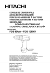
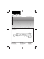
6702D (cover) (’97. 1. 20) Cordless Angle Socket Driver Instruction Manual F Clé d’Angle sans Fil Manuel d’Instructions D Akku-Winkelschrauber Betriebsanleitung I Avvitatore Angolare a Batteria Istruzioni d’Uso Accu haakse moeraanzetter Gebruiksaanwijzing E Llave Angular a Batería Manual de Instrucciones P Aparafusadora Angular a Bateria Manual de Instruço˜es Akku Vinkelskruemaskine Brugsanvisning S Sladdlös Vinkelmutterdragare Bruksanvisning N Akku Vinkelmuttertrekker Bruksanvisning SF Akkukäyttöinen Kulmahylsyväännin Käyttöohje GR ∞Û‡ÚÌ·ÙÔ ‚ȉÔÙÚ‡·ÓÔ ÁˆÓȷ΋˜ ˘Ô‰Ô¯‹˜ √‰ËÁ›Â˜ ¯Ú‹Ûˆ˜ GB NL DK 6702D 6702DW 6702DW With fast charger Avec chargeur rapide Mit Schnellauflader Con caricatore veloce Met snellader Con cargador rápido Com carregador rápido Med hurtiglader Inkl. snabbladdare Med hurtiglader Pikalaturilla ªÂ Ù·¯˘ˇfiÚÙÈÛË 6702D (illust) (’97. 9. 12) 1 2 9.5 mm (3/8’’) or 6.35 mm (1/4’’) 3 4 5 6 7 8 2 6702D (illust) (’97. 1. 20) 9 3 6702D (E) (’97. 9. 16) ENGLISH 1 2 3 4 5 6 Battery cartridge Set plate Charging light Hole for detent pin Detent pin Square drive Explanation of general view 7 8 9 0 q Bit with Form C 6.3 shank Round drive Switch trigger Reversing switch Clockwise rotation SPECIFICATIONS Model 6702D Capacities Bolt, nut and machine screw ........... 3 mm – 6 mm Square drive ........................... 9.5 mm or 6.35 mm No load speed (RPM) ......................................... 400 Fastening torque ...................... 20 kg.cm – 80 kg.cm Overall length ............................................... 352 mm Net weight ....................................................... 1.4 kg Output ....................................................... D.C. 9.6 V Charging time ....................................... Approx. 1 hr. • Due to the continuing program of research and development, the specifications herein are subject to change without prior notice. • Note: Specifications may differ from country to country. Safety hints For your own safety, please refer to enclosed safety instructions. These symbols mean: Indoor use only Read instruction manual. DOUBLE INSULATION IMPORTANT SAFETY INSTRUCTIONS FOR CHARGER & BATTERY CARTRIDGE 1. SAVE THESE INSTRUCTIONS — This manual contains important safety and operating instructions for battery charger. 2. Before using battery charger, read all instructions and cautionary markings on (1) battery charger, (2) battery, and (3) product using battery. 3. CAUTION — To reduce risk of injury, charge only MAKITA type rechargeable batteries. Other types of batteries may burst causing personal injury and damage. 4. Do not expose charger to rain or snow. 5. Use of an attachment not recommended or sold by the battery charger manufacturer may result in a risk of fire, electric shock, or injury to persons. 6. To reduce risk of damage to electric plug and cord, pull by plug rather than cord when disconnecting charger. 7. Make sure cord is located so that it will not be stepped on, tripped over, or otherwise subjected to damage or stress. 4 w e r t y Counterclockwise rotation Number Adjusting ring Red mark Screw 8. Do not operate charger with damaged cord or plug — replace them immediately. 9. Do not operate charger if it has received a sharp blow, been dropped, or otherwise damaged in any way; take it to a qualified serviceman. 10. Do not disassemble charger or battery cartridge; take it to a qualified serviceman when service or repair is required. Incorrect reassembly may result in a risk of electric shock or fire. 11. To reduce risk of electric shock, unplug charger from outlet before attempting any maintenance or cleaning. Turning off controls will not reduce this risk. ADDITIONAL SAFETY RULES FOR CHARGER & BATTERY CARTRIDGE 1. Do not charge battery cartridge when temperature is BELOW 10°C (50°F) or ABOVE 40°C (104°F). 2. Do not attempt to use a step-up transformer, an engine generator or DC power receptacle. 3. Do not allow anything to cover or clog the charger vents. 4. Always cover the battery terminals with the battery cover when the battery cartridge is not used. 5. Do not short the battery cartridge: (1) Do not touch the terminals with any conductive material. (2) Avoid storing battery cartridge in a container with other metal objects such as nails, coins, etc. (3) Do not expose battery cartridge to water or rain. A battery short can cause a large current flow, overheating, possible burns and even a breakdown. 6. Do not store the machine and battery cartridge in locations where the temperature may reach or exceed 50°C (122°F). 7. Do not incinerate the battery cartridge even if it is severely damaged or is completely worn out. The battery cartridge can explode in a fire. 8. Be careful not to drop, shake or strike battery. 9. Do not charge inside a box or container of any kind. The battery must be placed in a well ventilated area during charging. 6702D (E) (’97. 9. 19) ADDITIONAL SAFETY RULES FOR MACHINE 1. Be aware that this machine is always in an operating condition, because it does not have to be plugged into an electrical outlet. 2. Always be sure you have a firm footing. Be sure no one is below when using the machine in high locations. 3. Hold the machine firmly. 4. When driving into walls, floors or wherever ‘‘live’’ electrical wires may be encountered, DO NOT TOUCH ANY METAL PARTS OF THE MACHINE! Hold the machine only by the insulated grasping surfaces to prevent electric shock if you drive into a ‘‘live’’ wire. 5. Check the socket carefully for wear, cracks or damage before installation. SAVE THESE INSTRUCTIONS. OPERATING INSTRUCTIONS Installing or removing battery cartridge (Fig. 1) • Always switch off the machine before insertion or removal of the battery cartridge. • To remove the battery cartridge, pull out the set plate on the machine and grasp both sides of the cartridge while withdrawing it from the machine. • To insert the battery cartridge, align the tongue on the battery cartridge with the groove in the housing and slip it into place. Snap the set plate back into place. Be sure to close the set plate fully before using the machine. • Do not use force when inserting the battery cartridge. If the cartridge does not slide in easily, it is not being inserted correctly. Charging (Fig. 2) Plug the fast charger into your power source. Insert the battery cartridge so that the plus and minus terminals on the battery cartridge are on the same sides as their respective markings on the fast charger. The charging light will come on and charging will begin. If the charging light goes out soon, remove the battery cartridge from the charger and let it cool off for more than one minute. Then re-insert it and try to charge it once more. If the charging light goes out within one minute even after repeating this procedure a couple of times, the battery cartridge is dead. Replace it with a new one. When the charging light goes out after about one hour, you may remove the fully charged battery cartridge. After charging, unplug the charger from the power source. Battery type 9100 Capacity (mAH) 1,300 Number of cells 8 CAUTION: • Your new battery cartridge is not charged. You will need to charge it before use. • If you try to charge a cartridge from a just-operated machine, sometimes the charging light will not come on. If this occurs, let the cartridge cool off for a while. Then re-insert it and try to charge it once more. • When you charge a new battery cartridge or a battery cartridge which has not been used for a long period, it may not accept a full charge. This is a normal condition and does not indicate a problem. You can recharge the battery cartridge fully after discharging it completely a couple of times. • If you wish to charge two battery cartridges, allow 15 minutes between chargings on the fast charger. Installing or removing socket Important: Always be sure that the machine is switched off and the battery cartridge is removed before installing or removing the socket. For machine with square drive (Fig. 3 & 4) Use 9.5 mm square drive socket with a hole for detent pin which is available on the market. (Note: Use 6.35 mm square drive socket when using the machine with 6.35 mm square drive.) To install the socket, depress the detent pin on the square drive with your finger and push the socket onto the square drive until the detent pin is inserted into the hole in the socket. To remove the socket, depress the detent pin with a small hand tool and pull off the socket. For machine with round drive (Fig. 5) Use a bit with Form C 6.3 shank which is available on the market. The bit can be inserted directly into the round drive and held in place. To install the bit, push it firmly into the round drive. To remove the bit, grasp it with a pair of pliers and pull it out of the round drive. Sometimes, it helps to wiggle the bit with the pliers as you pull. Switch action (Fig. 6) CAUTION: Before inserting the battery cartridge into the machine, always check to see that the switch trigger actuates properly and returns to the ‘‘OFF’’ position when released. To start the machine, simply pull the trigger. Release the trigger to stop. 5 6702D (E) (’97. 9. 19) Reversing switch action (Fig. 7) CAUTION: • Always check the direction of rotation before operation. • Use the reversing switch only after the machine comes to a complete stop. Changing the direction of rotation before the machine stops may damage the machine. This machine has a reversing switch to change the direction of rotation. Slide the reversing switch up for clockwise rotation or slide it down for counterclockwise rotation. Overload protector The overload protector automatically cuts out to break the circuit whenever heavy work is prolonged. Wait 20 – 30 seconds before resuming operation. Adjusting the fastening torque (Fig. 8) The fastening torque can be adjusted infinitely from approx. 20 kg·cm to 80 kg·cm. To adjust it, loosen the two screws and turn the adjusting ring. Then tighten the screws to secure the adjusting ring. Refer to the table below for relation between the numbers on the adjusting ring and the fastening torque to be obtained. Numbers on adjusting ring 1 2 3 4 5 Fastening torque to be obtained 20 kg·cm 35 kg·cm 48 kg·cm 60 kg·cm 80 kg·cm (Example) 35 kg·cm of fastening torque can be obtained when the number 2 is aligned to the red mark. NOTE: • Always tighten the two screws to secure the adjusting ring after adjusting the fastening torque. • The fastening torque may differ depending upon the kind of screws, the type of materials to be fastened, etc. Before starting your job, always perform a test operation to verify the adequate fastening torque. Operation The proper fastening torque may differ depending upon the kind or size of screws, the type of materials to be fastened, the condition of the threads, etc. Before starting your job, always perform a test operation to verify adequate fastening torque. Hold the machine firmly with both hands whenever possible and place the socket over the bolt or nut. Then turn the machine on. As soon as the bolt or nut becomes tight, the clutch will cut in and the motor will stop automatically. Release the switch trigger. When fastening machine screws, use the proper screwdriver bit shown in Fig. 9. It is commonly available on the market. NOTE: • Always use the correct size socket for bolts and nuts. An incorrect size socket will result in inaccurate and inconsistent fastening torque and/or damage to the bolt or nut. • Hold the machine with its square drive pointed straight at the bolt or nut, or the bolt or nut will be damaged. • If the motor will not start even after you pull the trigger, release the trigger. Then pull the trigger again after turning the socket slightly with your fingers. Fastening performance The following reference table indicates the approximate fastening capacity from a single 1-hour battery charge. It may differ under some conditions. Screw size M6 x 14 Fastening torque 5 1 MAINTENANCE CAUTION: Always be sure that the machine is switched off and the battery cartridge is removed before carrying out any work on the machine. To maintain product safety and reliability, repairs, maintenance or adjustment should be carried out by Makita Authorized Service Center. 6 Fastenings About 800 screws About 1,000 screws 6702D (Nl) (’97. 9. 19) NEDERLANDS 1 2 3 4 5 6 Verklaring van algemene gegevens Batterij Sluitplaat Oplaadlampje Gat voor borgpen Borgpen Vierkante aandrijfas 7 8 9 0 q Bit met Vorm C 6.3 schacht Ronde aandrijfas Trekschakelaar Omkeerschakelaar Rechtse draairichting TECHNISCHE GEGEVENS Model 6702D Capaciteit Bout-, moeren machineschroefmaat ................... 3 mm – 6 mm Vierkant ................................... 9,5 mm of 6,35 mm Toerental onbelast/min. ....................................... 400 Aantrekkoppel .......................... 20 kg.cm – 80 kg.cm Totale lengte ................................................ 352 mm Netto gewicht .................................................. 1,4 kg Accuspanning ............................................. DC 9,6 V Oplaadtijd ................................................. Ong. 1 uur • In verband met ononderbroken research en ontwikkeling behouden wij ons het recht voor bovenstaande technische gegevens te wijzigen zonder voorafgaande kennisgeving. • Opmerking: De technische gegevens kunnen van land tot land verschillen. Veiligheidswenken Voor uw veiligheid dient u de bijgevoegde Veiligheidsvoorschriften nauwkeurig op te volgen. Deze symbolen betekenen: Alleen voor gebruik binnenshuis Lees de gebruiksaanwijzing. DUBBELE ISOLATIE BELANGRIJKE VEILIGHEIDSVOORSCHRIFTEN VOOR GEBRUIK VAN DE BATTERIJLADER EN HET BATTERIJPAK 1. BEWAAR DEZE VOORSCHRIFTEN — In deze gebruiksaanwijzing staan belangrijke veiligheidsen bedieningsvoorschriften betreffende de batterijlader (snellader). 2. Lees alle voorschriften en waarschuwingen betreffende (1) de batterijlader, (2) het batterijpak en (3) het gereedschap aandachtig door alvorens de batterijlader in gebruik te nemen. 3. LET OP — Om het gevaar voor ongelukken te verminderen, dient u met de snellader uitsluitend MAKITA oplaadbare batterijen te laden. Batterijen van andere merken kunnen gaan barsten en hierdoor verwondingen of schade veroorzaken. w e r t y Linkse draairichting Getal Instelring Rood merkteken Schroef 4. Stel de batterijlader niet bloot aan regen of sneeuw. 5. Het gebruik van accessoires die niet door de fabrikant van de batterijlader worden verkocht of aanbevolen, kan brandgevaar, elektrische schok of verwondingen veroorzaken. 6. Om de stekker en het netsnoer niet te beschadigen, trekt u het netsnoer uit het stopkontakt door de stekker vast te pakken. 7. Let op dat het snoer zodanig op de grond ligt, dat niemand erop kan stappen of erover kan struikelen en dat er niets op het snoer geplaatst wordt. 8. Gebruik in geen geval de batterijlader als het netsnoer of de stekker beschadigd is. Vervang deze onmiddellijk. 9. Gebruik de batterijlader ook niet als deze gevallen is, aan een zware stoot heeft blootgestaan, of als u vermoedt dat hij beschadigd is. Laat in deze gevallen de batterijlader eerst nakijken. 10. Haal de batterijlader of het batterijpak niet uit elkaar; laat eventuele servicebeurten of reparaties uitsluitend vakkundig uitvoeren. Het onjuist opnieuw in elkaar zetten kan namelijk elektrische schok of brandgevaar opleveren. 11. Om gevaar voor elektrische schok te verminderen, trekt u de stekker uit het stopkontakt alvorens de batterijlader te reinigen of een onderhoudsbeurt te geven. Door de batterijlader alleen maar uit te schakelen, vermindert u dit gevaar niet. BIJGEVOEGDE VEILIGHEIDSVOORSCHRIFTEN VOOR GEBRUIK VAN DE BATTERIJLADER EN HET BATTERIJPAK 1. Laad het batterijpak niet op als de temperatuur LAGER is dan 10°C of HOGER dan 40°C. 2. Gebruik voor het laden nooit een step-up transformator, een dynamo of een gelijkstroombron. 3. Zorg dat de ventilatiegaten van de batterijlader niet afgesloten worden of verstopt raken. 4. Bedek altijd de polen van de accu met het accudeksel wanneer u de accu niet gebruikt. 19 6702D (Nl) (’97. 9. 19) 5. Voorkom kortsluiting van het batterijpak: (1) Raak de aansluitklemmen nooit aan met geleidend materiaal. (2) Bewaar het batterijpak niet op een plaats waar ook andere metalen voorwerpen zoals spijkers, munten e.d. worden bewaard. (3) Stel het batterijpak niet bloot aan water of regen. Kortsluiting van het batterijpak kan leiden tot een grote stroomafgifte, oververhitting, brandwonden of zelfs tot defecten. 6. Bewaar de batterijlader en het batterijpak niet in plaatsen waar de temperatuur tot 50°C of hoger kan op lopen. 7. Werp zwaar beschadigde of volledig uitgeputte batterijpakken niet in het vuur, omdat een gevaarlijke explosie er het gevolg van kan zijn. 8. Wees voorzichtig dat u het batterijpak niet laat vallen en het niet aan schokken of stoten blootstelt. 9. Laad het batterijpak niet op in een kist, een container e.d. Om het batterijpak op te laden, dient u dit in een goed geventileerde ruimte te plaatsen. BIJGEVOEGDE VEILIGHEIDSVOORSCHRIFTEN VOOR DE MACHINE 1. Wees op uw hoede. Dit gereedschap is altijd gereed voor gebruik, aangezien het niet op een stopkontakt hoeft te worden aangesloten. 2. Zorg ervoor dat u stevig staat op een vaste ondergrond. Bij gebruik van het gereedschap op een hoge plaats dient u ervoor te zorgen dat niemand beneden u aanwezig is. 3. Houd het gereedschap stevig vast. 4. Bij inschroeven in muren, vloeren en dergelijke bestaat het gevaar dat u onder spanning staande elektrische kabels tegenkomt. RAAK DERHALVE DE METALEN DELEN VAN HET GEREEDSCHAP NIET AAN! Houd het gereedschap uitsluitend vast bij de geisoleer- de handgreep ter vermijding van elektrische schok in het geval dat het gereedschap in aanraking komt met een onder spanning staande kabel. 5. Controleer alvorens te installeren de schroefdop zorgvuldig op slijtage, barsten of beschadigingen. BEWAAR DEZE VOORSCHRIFTEN. 20 BEDIENINGSVOORSCHRIFTEN Plaatsen en uithalen van batterij (Fig. 1) • Schakel de machine altijd uit voordat een batterij geplaatst of verwijdert wordt. • Om het batterijpak te verwijderen, trek eerst de sluitplaat uit de machine, pak dan het batterijpak aan beide zijden vast en verwijder het uit de machine. • Voor het plaatsen van de batterij zorgt u ervoor dat de rug op de batterij in de groef van het batterijkompartiment komt, waarna u de batterij naar binnen schuift. Klap alvorens het gereedschap te gebruiken de stelplaat oftewel deksel weer dicht, kontroleer of de stelplaat goed vast geklemd zit en niet gemakkelijk opengaat. • Als het batterijpak moeilijk in de houder komt, probeer het dan niet met geweld in te duwen. Indien het batterijpak er niet gemakkelijk ingaat, dan houdt u het verkeerd. Opladen (Fig. 2) Sluit de snellader aan op het stopcontact. Plaats het batterijpak zo in de snellader dat de plus en min tekens op het batterijpak overeenkomen met de plus en min tekens op de snellader. Het oplaadlampje zal aangaan en het opladen zal beginnen. Indien het oplaadlampje spoedig uitgaat, moet u het batterijpak uit de batterijlader verwijderen en het langer dan één minuut laten afkoelen. Plaats daarna het batterijpak opnieuw erin en probeer nogmaals om het op te laden. Indien het oplaadlampje binnen één minuut uitgaat zelfs nadat u deze procedure enkele malen hebt herhaald, is het batterijpak versleten. Vervang het door een nieuw batterijpak. Wanneer het oplaadlampje na ongeveer één uur uitgaat, is het batterijpak volledig opgeladen en kunt u dit verwijderen. Na oplading, trek de stekker van de oplader uit het stopcontakt. Accu-model 9100 Capaciteit (mAH) 1 300 Aantal cellen 8 6702D (Nl) (’97. 9. 19) LET OP: • Uw nieuwe batterijpatroon is niet geladen. U moet ze voor gebruik laden. • Wanneer u het batterijpak van een zojuist gebruik gereedschap laadt, gebeurt het weleens dat het laadlichtje niet brandt. Verwijder in dit geval het batterijpak van de lader en laat het eerst afkoelen. Steek het daarna weer in de lader. • Wanneer u een nieuw batterijpak laadt, of een batterijpak dat lang niet is gebruikt, kan het gebeuren dat u het niet maximaal op kunt laden. Dit is echter normaal en duidt niet op een defekt. Nadat het batterijpak een paar keer volledig is ontladen, kunt u het volledig laden. • Als U twee batterijen wil opladen geeft dan de oplader tussendoor 15 minuten rust. Installeren of verwijderen van de dop Belangrijk: Schakel het gereedschap uit en verwijder het batterijpak, alvorens de dop te installeren of te verwijderen. Voor gereedschap met een vierkante aandrijfas (Fig. 3 en 4) Gebruik een in de handel verkrijgbare 9,5 mm dop voor vierkante aansluiting die voorzien is van een gat voor een borgpen. (Let op: Gebruik een 6,35 mm dop wanneer u het gereedschap met 6,35 mm vierkante aandrijfas gebruikt.) Om de dop te installeren, druk de borgpen op de vierkante aansluiting met uw vinger naar binnen en duw dan de dop op de vierkante aandrijfas totdat de borgpen in het gat in de dop komt te zitten. Om de dop te verwijderen, druk de borgpen met een klein gereedschap naar binnen en trek de dop eruit. Voor gereedschap met een ronde aandrijfas (Fig. 5) Gebruik een in de handel verkrijgbare schroefbit met een Vorm C 6.3 schacht. U kunt de schroefbit direct in de ronde aandrijfas steken en deze vastzetten. Om de schroefbit te installeren, deze stevig in de ronde drijfkop duwen. Om de schroefbit te verwijderen, de schroefbit met een tang vastpakken en deze uit de ronde drijfkop trekken. Dit verloopt soms gemakkelijker indien u de schroefbit met de tang een beetje doet wiegelen tijdens het trekken. Werking van de schakelaar (Fig. 6) LET OP: Alvorens het batterijpak in het gereedschap te plaatsen, kontroleert u altijd eerst even of de trekschakelaar behoorlijk funktioneert en bij het loslaten naar de ‘‘OFF’’ positie terugkeert. Werking van de omkeerschakelaar (Fig. 7) LET OP: • Kontroleer altijd de draairichting alvorens het gereedschap te gebruiken. • Zet de omkeerschakelaar alleen in de andere stand, nadat het gereedschap volledig tot stilstand is gekomen. Indien u dit nalaat kan het gereedschap zware beschadiging oplopen. Dit gereedschap is voorzien van een omkeerschakelaar voor het veranderen van de draairichting. Druk de omkeerschakelaar naar boven voor een rechtse en naar beneden voor een linkse draairichting. Beveiliging tegen overbelasting De beveiliging tegen overbelasting slaat automatisch af om het circuit te verbreken telkens wanneer zwaar werk voor lange tijd wordt voortgezet. Wacht 20 – 30 sekonden alvorens het werk te hervatten. Instellen van het aandraaimoment (Fig. 8) Het aandraaimoment kan worden ingesteld op een willekeurige waarde tussen ongeveer 20 kg.cm en 80 kg.cm. Om in te stellen, de twee schroeven losdraaien en de instelring verdraaien. Draai daarna de twee schroeven aan om de instelring vast te zetten. Raadpleeg de onderstaande tabel voor de verhouding tussen de getallen op de instelring en de aandraaimomenten. Getallen op de instelring 1 2 3 4 5 Overeenkomstig aandraaimoment 20 kg.cm 35 kg.cm 48 kg.cm 60 kg.cm 80 kg.cm (Voorbeeld) Om een aandraaimoment van 35 kg.cm te krijgen, dient het getal 2 vlak tegenover het rode merkteken te liggen. OPMERKING: • Trek na het instellen van het aandraaimoment altijd de twee schroeven aan om de instelring vast te zetten. • Het juiste aandraaimoment hangt af van het soort schroeven, het soort materiaal waarin u de schroeven vastdraait, enz. Neem altijd een proef voor het vaststellen van het juiste aandraaimoment, alvorens met het eigenlijke werk te beginnen. Om het gereedschap te starten hoeft u de trekschakelaar slechts in te drukken en deze los te laten om het gereedschap te stoppen. 21 6702D (Nl) (’97. 9. 19) Bediening Het juiste aandraaimoment hangt af van het soort of de afmeting van de schroef, het soort materiaal waarin U de schroef wenst vast de draaien, de conditie van de schroefdraad, enz. Het is derhalve wenselijk alvorens het eigenlijke werk te doen, altijd een proef te nemen voor het vastellen van het juiste aandraaimoment. Houd het gereedschap zoveel mogelijk met beide handen stevig vast en plaats de dop op de bout of moer . Schakel het gereedschap vervolgens in. Zodra de bout of moer vastzit, raakt de koppeling los en komt de motor automatisch tot stilstand. Laat vervolgens de trekschakelaar los. OPMERKINGEN: • Gebruik altijd de juiste met de bout en moer overeenkomstige dopmaat. Een verkeerde dopmaat leidt tot een onnauwkeurig en onbestendig aandraaimoment en beschadiging van de bout of moer. • Houd het gereedschap vast met de vierkante aandrijfas haaks op de bout of moer, aangezien anders deze beschadiging op kan lopen. • Wanneer de motor na het indrukken van de trekschakelaar niet wilt starten, laat de trekschkalaar los. Draai met uw vingers de dop even om en druk vervolgens de trekschakelaar weer in. Voor het vastdraaien van machineschroeven dient U in de Fig. 9 aangegeven schroevendraaier te gebruiken. Deze is overal los verkrijgbaar. Aantal vast te draaien bouten Kijk naar de onderstaande tabel voor het aantal mogelijk vast te draaien bouten met een batterijlading van één uur. Schroefmaat M6 x 14 Aantrekoppel 5 1 ONDERHOUD LET OP: Controleer altijd of het gereedschap is uitgeschakeld en de accu is losgekoppeld vooraleer onderhoud uit te voeren aan de machine. Opdat het gereedschap veilig en betrouwbaar blijft, dienen alle reparaties, onderhoud of afstellingen te worden uitgevoerd bij een erkend Makita service centrum. 22 Aantal vastdraaiingen Ongeveer 800 Ongeveer 1 000