1
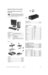
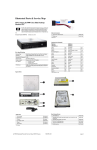
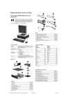
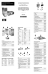
Service Reference Card
HP Compaq dx7200 and dc7600 Series Personal Computers
Computer Setup Menu (Continued)
© 2005 Hewlett-Packard Development Company, L.P. The information contained herein is sub-
Heading
ject to change without notice. HP shall not be liable for technical or editorial errors or omissions
contained herein. Intel, Pentium, Intel Inside, and the Intel logo are trademarks or registered
trademarks of the Intel Corporation and its subsidiaries in the U. S. and other countries.
Storage
(continued)
Document Number 403314-001.
Option / Description
Storage
SATA Emulation. Allows method of accessing SATA
Options (ctd) controller and devices. Default is Separate IDE Controller. Option is combined IDE Controller
IDE Controller. Enable/disable primary IDE controller.
1st Edition August 2005.
Primary SATA Controller - Enable/disable.
Key Specifications
Processor Type:
Secondary SATA Controller - Enable/disable.
DPS Self-Test - Allows execution of self-tests on ATA hard drives capable of Drive Protection System (DPS) tests.
Intel Pentium 4, Intel Pentium D, or Intel Celeron D
RAM Type:
DDR PC2 4200 and PC2 5300 non-ECC
Maximum RAM Supported:
up to 4 GB depending on the model [1]
Boot Order - Allows selection of priority in the boot sequence. Each
drive may be included or excluded. May use F9 on rebooting to select a
one time boot override to a selected bootable device.
Expansion Bus:
PCI 2.3, PCI Express
Graphics Adapter
Integrated controller, PCI Express or PCI 2.3 support
depending on model
Hard drive interface:
SATA
Setup Password - Enable/disable setup (administrator) password.
I/O Interfaces:
Serial (1 std, 1 optional {2}), parallel (1 [3]), USB 2.0
(8), diskette drive (1), RJ-45 (1) Audio in and out (front
and rear)
Power-On Password - Enable/disable power-on password.
Security
Password Options (appears if Power-On or Setup password is set) Enable/disable password for warm boot.
Smart Cover Lock (some models) - Enable/disable Smart Cover Lock.
[1] USDT supports only 3 GB RAM
[2] No option of MT
[3] Plus 1 optional on USDT
Embedded Security - Enable/disable Embedded Security device. Reset
device to Factory Settings.
Device Security - Enable/disable serial/parallel/USB ports, system
audio, NIC (some models).
System Setup and Boot
Network Service Boot - Enables/disables Network Service Boot (some
models).
Basic system information regarding file, storage, security, and power configuration is maintained in the Setup Utility held in the system ROM. The Setup Utility is accessed by
pressing the F10 key as soon as the computer is turned on. If the screen prompt opportunity is
missed, a restart will be necessary.
System IDs - Allows setting of Asset and Ownership Tags, chassis serial
number, keyboard locale, and Universal Unique Identifier (UUID).
DriveLock -Manages passwords and security states for drives that support the ATA Security command set.
Note: Not all features are available on all models.
OS Security - Enable /disable Data Execution Prevention; Enable/disable Intel Virtualization.
Computer Setup Menu
Heading
File
Data Execution Prevention - Enable/disable to prevent OS Security
breaches.
Option / Description
System Information - Lists product name, processor type/speed/stepping, cache size, installed memory size/speed, no. channels, integrated
MAC for enabled or embedded NIC, system ROM BIOS/family name/
version, chassis serial number, and asset tracking number.
Power
Set Time and Date - Allows selection of system time and date.
Flash System ROM - Allows selection of a drive containing a new
BIOS.
OS Power Management - Enable/disable processor voltage and frequency during run and idle times; ACPI S3 support; USB Wake on
Device Insertion.
Hardware Power Management - Enable/disable SATA bus and/or device
power management.
About - Provides copyright information.
Thermal - Fan idle mode to control minimum fan speed.
Default Setup - Allows both saving current settings and restoring factory
settings as defaults.
Power-On Options - Select POST mode for QuickBoot, FullBoot, FullBoot every 1-30 days; Enable/disable POST messages; Enable/disable
option ROM prompt; Enable/disable I/O APIC mode; Select computer
state after power loss; Select wakeup boot source; Enable/disable POST
delay (for slow hard drives); Enable/disable ACPI/USB buffers; Enable/
disable Hyper-threading; Enable/disable SetUp Browse Mode; Limit
CPUID to max value of 3.
Apply Defaults and Exit - Applies currently selected default settings and
clears all passwords.
Executive Memory Test - Restarts computer and executes POST memory test.
Ignore Changes and Exit - Exits Computer Setup without applying or
saving any changes.
BIOS Power-On - Set computer to turn on at specific time of day.
Replicated Setup -Allows saving to and restoring from removable
media.
Advanced
(advanced
users only)
Onboard Devices - Set resources for onboard devices (serial/parallel
port or diskette controller).
Save Changes and Exit - Saves changes to system configuration and
exits Computer Setup.
Storage
Smart Card Options - Enable/disable Smart Card to be used in place of
Power-On Password.
PCI Devices - Lists currently installed PCI devices and IRQ settings.
Allows configuration/disabling of devices (no effect on APIC systems)
Device Configuration - Lists all installed BIOS storage devices. The following options appear when a device is selected.
Bus Options - Enable/disable PCI bus mastering, PCI VGA palette
snooping, PCI SERR# function, and ECC on select systems.
Diskette Type (legacy diskette drives only) Identifies the
highest capacity media type accepted by the diskette
drive.
Device Options - Set printer mode (bidirectional output only); Num
Lock State; Wake-up events; processor cache; unique sleep state blink
patterns; integrated video; monitor tracking; NIC PXE Option ROM
download.
Drive Emulation (IDE devices only) Selects drive type
emulation for storage
Drive Type
ATAPI Zip
Drive
None (treated as other), diskette
(treated as diskette drive).
ATA Hard drive None (treated as other), disk (treated
as hard drive.
Legacy
Diskette
No emulation available.
IDE CD-ROM
No emulation available.
ATAPI LS-120
None (treated as other), diskette
(treated as diskette drive).
Default Values IDE/SATA
Multisector Transfers (ATA disks only). Selects number
of sectors transferred. Options are disabled, 8, and 16.
Transfer Mode (ATA devices only). Selects active data
transfer mode. Options are PIO 0, Max PIO, Enhanced
DMA, Ultra DMA 0, and Max UDMA.
Translation Mode (ATA disks only). Selects translation
mode to enable the BIOS to access disks partitioned and
formatted on other systems and may be necessary for
users of older versions of Unix. Options are: Automatic,
Bit-Shift, LBA Assisted, User, and None.
NOTE: The translation mode automatically selected by
BIOS should usually not be changed.
Translation Parameters (ATA disks only). Allows you to
specify disk parameters logical cylinders (max. of 1024),
heads (max. of 256), and sectors per track (max. of 63)
used by BIOS to translate disk I/O requests. Fields are
visible and changeable only when drive translation mode
is set to User.
Storage
Options
PCI VGA Configuration - Allows selection of VGA controller (if multiple PCI video controllers are installed).
Emulation Options
Removable Media Boot. Enables/disables ability to boot
system from removable media.
Legacy Diskette Write. Enables/disables ability to write
data to legacy diskettes.
BIOS DMA Data Transfers. Allows control of BIOS I/O
requests. Enable allows read and write with DMA transfers. Disable allows read and write with PIO transfers.
Failsafe Boot Block ROM
The Boot Block is a flash-protected section of the ROM that contains code that checks for a
valid system BIOS image when the system is turned on.
- If the system BIOS image is valid, the system starts normally.
- If the system BIOS image is not valid, a failsafe Boot Block BIOS provides enough
support to:
- search remopvable media for BIOS image files. If an appropriate BIOS image is
found, it is automatically flashed into the ROM.
- start the system from bootable removable media that automaticaly invokes system
BIOS upgrade utilities.
When an invalid system BIOS image is detected, the system power LED will blink red 8 times,
one blink every second. Simultaneously, the speaker will beep 8 times. If the portion of the system ROM containing the video option ROM image is not corrupt, “Boot Block Emergency
Recovery Mode” will be displayed on the screen. To recover the system after it enters Boot
Block Emergency Recovery Mode, complete the following steps:
1. Remove all removable media removable storage options.
2. Turn off the power.
3. Insert a diskette, CD, or USB flash device containing the desired BIOS image file in the root
directory.
Note: The media must be formatted using the FAT 12, FAT 16, or FAT 32 file system.
4. Turn on power to the system. If no appropriate BIOS image is found, the failsafe Boot Block
BIOS will attempt to start the system from a bootable device. If no bootable device is found, you
will be prompted to insert media containing a BIOS image file or BIOS upgrade utility. If the
system successfully reprograms the ROM, the system will automatically restart.
Security Functions
The system offers independent Power-On and Setup passwords for system and data protection.
The Power-On password protects the computer from unauthorized access by prompting the user
for a password during power up. The Setup password protects the computer from unauthorized
or inadvertent re-configuration of legacy device resource settings or ROM flash upgrade by
prompting the user for a password prior to entering the Setup Utility.
To establish a password:
1.
Turn on or restart the computer. If you are in Windows, click Start > Shut Down >
Restart the computer.
Security Functions (Continued)
2.
3.
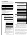
Error Conditions and Messages
As soon as the computer is turned on, press and hold F10 until you enter Computer Setup.
Press Enter to bypass the title screen, if necessary. If you do not press F10
as soon as the computer starts, a restart will be necessary.
Select Security, then select Setup Password or Power-On Password and follow the
instructions on the screen.
Before exiting, click File > Save Changes and Exit.
To change a Power-On or Setup password:
1.
Power LED
# Beeps
Steady green
None
NOTE: Type the new password carefully since the actual characters do not appear
on the screen.
Press the enter key.
Event
S0 System on (normal operation)
Blinks green @ 0.5 Hz
None
S1 Suspend
Blinks green @ 0.5 Hz
None
S3 Suspend to RAM
Off (clear)
None
S4 Suspend to disk
Off (clear)
None
S5 Soft off
Blinks red 2 times @ 1 Hz [1]
2
Processor thermal shutdown
Blinks red 3 times @ 1 Hz [1]
3
Processor not seated / installed
Blinks red 4 times @ 1 Hz [1]
4
Power supply failure
Blinks red 5 times @ 1 Hz [1]
5
Memory error
Blinks red 6 times @ 1 Hz [1]
6
Video error
Blinks red 7 times @ 1 Hz [1]
7
PCA failure
Turn on or restart the computer. If you are in Windows, click Start > Shut Down >
Restart the Computer. Run Computer Setup (F10).
When the key icon appears, type your current password, a slash (/) or alternate delimiter character, your new password, another slash (/) or alternate delimiter character, and your
new password again as shown:
current password/new password/new password.
2.
Chassis LED and Beep Messages
The new password will take effect the next time the computer is restarted.
Blinks red 8 times @ 1 Hz [1]
8
Invalid ROM checksum (error)
To delete a password using Setup:
Blinks red 9 times @ 1 Hz [1]
9
Wrong power supply input voltage
1.
Turn on or restart the computer. If you are in Windows, click Start > Shut Down >
Restart the Computer. To delete the setup password, run Computer Setup (F10).
Blinks red 10 times @ 1 Hz [1]
10
Bad option card
2.
When the key icon appears, type your current password followed by a slash (/) or
alternate delimiter character as shown. Example: currentpassword/
3.
Press the Enter key.
NOTE: Power LED blinks are repeated after a 2 second pause until issue is resolved,.
Beeps continue for 5 iterations and then stop.
Common POST Error Messages
To delete or disable the Power On and Setup passwords:
1.
Shut down (Power down) the system and disconnect the power cord from the outlet
or the system unit.
2.
Remove the chassis cover.
3.
On the system board, remove the jumper on pins 1 and 2 of header E49 and place
only on pin 2.
4.
Replace the chassis cover and reconnect the power cord.
Screen
Message
Beeps
101-Option
ROM Error
1L, 1S
103-System
Board
Failure
none
Feature
Purpose
How It Is
Established
Removable Media
Boot Control
Prevents booting from removable media
drives.
Setup Utilities. [1]
164-Memory
Size Error
2S
Serial, Parallel,
USB, or Infrared
Interface Control
Prevents data transfer through integrated
serial, parallel, USB, or infrared interface.
Setup Utilities. [1]
Power-On
Password
Prevents use of computer until password is
entered. Can apply to both initial startup
and restart.
Setup Utilities. [1]
201-Memory
Error
Setup Password
Prevents reconfiguration of computer until
password is entered.
Setup Utilities. [1]
Network Server
Mode
Provides unique security features for
computer used as server.
Setup Utilities. [1]
DriveLock [3]
Prevents unauthorized access to data on
drives supporting password protection.
Setup Utilities. [1]
Smart
Cover Lock [2, 3]
Software-controllable solenoid that, when
activated, prevents unauthorized access to
chassis interior.
Setup Utilities. [1]
Smart
Cover Sensor [3]
Indicates computer cover or side panel has
been removed. Can be set to require
password for restart after cover or panel
removal.
Setup Utilities. [1]
Drive Protection
System (DPS
Diagnostic tool built into hard drives on
select models designed to discover
problems that might result in unwarranted
drive replacement.
Setup Utilities or
Diagnostics for
Windows.
Memory Change
Alerts
Detects addition or removal of memory
modules. Notifies system administrator.
Refer to Intelligent
Manageability
Guide.
Ownership Tag
Displays ownership information as defined
by system administrator during system
startup. (Protected by setup password).
Setup Utilities. [1]
Kensington
CableLock
Provision
Inhibits access to interior of computer
Requires Kensington
chassis. Can also be used to secure
cable lock accessory
computer to a fixed object for prevent theft. to secure computer
to a fixed object.
NOTES:
[1] For more information about Setup Utilities refer to the Computer Setup Guide.
[2] If for any reason the Setup utility is not accessible to unlock the Smart Cover Lock
then a FailSafe key is required to bypass the Smart Cover Lock and open the computer.
Refer to the Hardware Reference Guide on how to use the FailSafe key. To order a FailSafe key contact HP.
[3] Available on some models.
Diagnostic Functions
Diagnostic functions are provided by the Setup Utility (in system ROM) and by Insight Diagnostics. Insight Diagnostics provides detailed system information including:
•
•
•
•
•
Processor type and speed
Memory amount, mapping, and integrity
Hardware peripheral availability/settings
Hard drive type, space used/available
System identification, asset tracking
Insight Diagnostics may be found on the Documentation CD that ships with the computers.
Recommended Action
1. Verify ROM, reflash if
required.
2. Remove suspected expansion
card, reboot.
3. Clear CMOS memory, reboot.
4. Replace system board.
DMA, timers
1. Clear CMOS memory.
2. Remove expansion boards.
3. Replace system board.
Incorrect memory
configuration.
1. Run Setup (F10).
2. Check DIMMs for proper
seating, proper type, and HP
compatibility.
3. Remove DIMMs singularly
and reboot to isolate faulty
DIMM.
none
RAM failure.
Same as 164.
214-DIMM
Configuration Warning
none
Populated DIMM
configuration is not
optimized.
Rearrange the DIMMs so that
each channel has the same
amount of memory.
301-, 304Keyboard
Error
none
Keyboard failure.
Check keyboard connection or
keys. Replace keyboard. If 304,
possible system board problem
501-Display
Adapter
Failure
1L, 2S
Graphics controller.
1. Reseat graphics card.
2. Check monitor connection.
3. Replace graphics card.
1720SMART
Hard Drive
Detects
Imminent
Failure
none
Hard drive is about to
fail.
Run drive protection system test
if available. Check for firmware
patch for erroneous error
message.
1794Inaccessible
devices
attached to
SAATA 1
and/or SATA
3
none
A device is attached to
SATA 1 and/or SATA
3.
If using Windows 2000 or
Windows XP, change “SATA
Emulation” to “Separate IDE
Controller” in Computer Setup.
If not using these operating
systems, relocate the devices to
SATA 0 or 1.
1796-SATA
Cabling
Error
none
One or more SATA
devices are improperly
attached.
Ensure SATA connections are
used in ascending order starting
with SATA 0.
NOTE: Setup password may be used in place of Power-on password to boot system.
Security Features
Probable Cause
1. System ROM
checksum error.
2. Expansion card.
3. CMOS corruption.
4. System board
NOTES: L = long, S = short