1
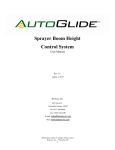
HEATLESS DESICCANT AIR DRYER
INSTRUCTION & MAINTENANCE MANUAL
MODEL RH203 THROUGH RH224
1
HEATLESS DRYER SERIES
INSTRUCTION AND MAINTENANCE MANUAL
IMPORTANT
BEFORE INSTALLING OR OPERATING THE DRYER IT IS RECOMMENDED THAT THIS
MANUAL BE STUDIED AND CLEARLY UNDERSTOOD.
SECTION
1.
TOPIC DESCRIPTION
SAFETY PRECAUTIONS
2.
INSTALLATION
3.
OPERATION
4.
MAINTENANCE & SYSTEM CHECK
5.
PREVENTIVE MAINTENANCE
6.
TROUBLESHOOTING GUIDE
7.
PARTS LIST
8.
PURGE CHART
9.
ELECTRICAL SCHEMATIC
2
1. SAFETY PRECAUTIONS
Warnings, Cautions, and Notes used in this manual have the following significance:
WARNING
MAINTENANCE OR OPERATING PROCEDURES AND TECHNIQUES
THAT WILL RESULT IN PERSONAL INJURY OR LOSS OF LIFE IF
NOT CAREFULLY FOLLOWED.
CAUTION
MAINTENANCE OR OPERATING PROCEDURES AND TECHNIQUES
THAT WILL RESULT IN DAMAGE TO EQUIPMENT IF NOT
CAREFULLY FOLLOWED.
NOTE
MAINTENANCE OR OPERATING PROCEDURES AND TECHNIQUES
THAT ARE CONSIDERED IMPORTANT ENOUGH TO EMPHASIZE.
3
2. INSTALLATION
Arrow Regenerative Air Dryers are shipped as completely assembly packages, filled with
desiccant ready to install.
Visually check the dryer to make certain that all air lines and electrical connections are
securely fastened and were not damaged in transit. If there is evidence of damage,
immediately enter a claim with the carrier, and notify your Arrow representative.
A.
APPLICATION CHECK AND ANALYSIS
To achieve the best dryer performance, you should carefully check that the design and
installation requirements outlined below are satisfied.
1. Operating pressure of your Arrow Dryer can range from 75 min to 150 max PSIG. Check
dryer label and ASME nameplate to verify maximum service pressure. Air available for
your air usage will vary with operating pressure.
2. The dryer should not be installed where compressed air and/or ambient temperature
exceeds 120°F or drops below +32°F. Locate dryer to avoid extremes of heat and cold
from other conditions. Best results occur when dryer is located as close to point of use
as practical. Where applicable, dryer towers should be insulated to reduce heat loss.
Avoid locating dryer outside or where it is exposed to the elements.
3. Dryers are sized according to airflow not pipe size. Dryer requires 10% to 15% of inlet
air (SCFM) for regeneration. The difference between the inlet and outlet flow is the
amount of purge air required. This air is purged to atmosphere and is not available for
use downstream. Make certain air supply to dryer meets your air demand plus purge air
requirements.
NOTE
DRYERS MUST BE SIZED FOR USABLE AIR REQUIRED PLUS PURGE AIR
WHICH EQUALS REQUIRED INLET AIR FLOW TO DRYER.
B.
MOUNTING SPECIFICATIONS AND DRYER LOCATION
1. Electrical connection must be hard piped with an external fused disconnect switch with
proper overload protection.
2. Frame must be suitably ground.
WARNING
ARROW DRYERS ARE WIRED FOR HIGH VOLTAGE. ONLY QUALIFIED
ELECTRICIANS ARE AUTHORIZED TO SERVICE THIS ELECTRICAL
EQUIPMENT.
4
3. Generally, locate your dryer downstream from the air receiver. The only exception would
be on applications with a fluctuating demand. Then the dryer should be located
upstream of the receiver to avoid air surges through the dryer’s desiccant beds.
4. Provide adequate space around the dryer for servicing. Bolt dryer skid to foundation,
where possible.
C.
SUGGESTED PIPING ARRANGEMENT
Wet air inlet is at the dryer’s bottom piping assembly. Dry outlet air is from the dryer’s top
piping assembly (see attached flow diagram).
In situations where air supply is required 24 hours a day (it is undesirable to interrupt the
airflow), a three valve bypass system is recommended to bypass the dryer. Use the fewest
elbows and taper connections necessary to keep pressure drop at a minimum.
D.
PREFILTERS / AFTERFILTERS
It is important that a prefilter and an afterfilter be provided in your dryer installation.
Prefilters, located before dryer, protect desiccant beds from contamination by oil, entrained
water, pipe scale, etc., thereby extending dryer desiccant life. Locate prefilters as close to
dryer as possible.
It is recommended that a mechanical separator be installed immediately preceding the
prefilter to remove the bulk liquid oil and entrained water.
CAUTION
LIQUID WATER SHOULD BE REMOVED BEFORE THE AIR ENTERS THE
DRYER. BE SURE SEPARATORS, PREFILTERS AND DRAINS ARE IN GOOD
WORKING ORDER.
After filters, located after the dryer, help eliminate the possibility of desiccant dusting and
carryover into the air system.
5
3. OPERATION
A.
START-UP
After all piping and electrical connections are made, proceed as follows:
1. SLOWLY pressurize the dryer. When the dryer reaches full operating pressure, check
the system for air leaks. Soap test all joints and fittings. To maintain desired dewpoint,
any leaks detected must be fixed, especially those on the outlet side of the dryer.
2. Adjust purge adjustment valve so that purge pressure gauge reads appropriate pressure
(see attached purge pressure chart).
3. Energize electrical circuit.
4. When electrical circuit has been energized, the control circuit board or mechanical timerwill start to operate and automatically initiate dryer operation. The timer is factory set, so
that no field adjustment is necessary.
NOTE
AT INITIAL START-UP, CHECK THE DRYER OPERATION FOR ONE OR TWO
CYCLES, ESPECIALLY AT THE TIME OF THE TOWER SHIFT. VERIFY THAT
ALL SYSTEMS ARE OPERATING IN THEIR PROPER ORDER AND
SEQUENCE. IF THE DRYER IS NOT FUNCTIONING PROPERLY, CONTACT
YOU ARROW REPRESENTATIVE.
B.
DRYER OPERATION
The dryer is fully automatic in operation and will now operate with a minimum of
maintenance and care. Each sequence of operations is programmed by a central circuit
board or mechanical timer. Dryer programs may differ slightly, but all perform similar
functions.
Standard dryers operate on a 10 minute NEMA cycle with 5 minutes drying and 5 minutes
regenerating.
At tower switchover, a 20 second time interval is allowed to bring both towers to full line
pressure before switchover, thus preventing rapid pressurization which would agitate the
desiccant bed. A special repressurization circuit is energized when the purge valve closes
to maintain a 30 second repressurization.
6
Repressurization takes place in a downward direction through the bed, minimizing desiccant
dusting.
C.
TIMER OPERATION
The dryer’s control circuit board or mechanical timer controls the complete cycle. No field
adjustment of any kind is required for proper operation.
D. ADJUSTABLE PURGE FLOW SYSTEM
RH-Series Exhaust Purge Dryers feature an adjustable purge flow system. The purge flow
system consists of:
1. Purge Flow Adjustment Valve
2. Purge Flow Meter (Gauge)
3. Purge Orifice (Located in pipe union)
The purge flow system is located between the twin towers of the dryer and/or above the
control box. The function of the purge flow system is to regulate the amount of purge air
allowed to flow into and subsequently regenerate the off-line (0 PSIG) tower.
The purge air flow is controlled by adjusting the purge flow valve to a specific setting as
indicated on the purge flow meter (gauge). Once set, the purge flow adjusting valve in
conjunction with the purge orifice plate will allow a certain fixed purge air flow.
7
CAUTION
TO MAINTAIN THE PROPER OUTLET DEWPOINT, THE DRYER MUST
RECEIVE THE PROPER AMOUNT OF PURGE AIR. IF THERE IS EXCESSIVE
BACK PRESSURE IN THE TOWER BEING REGENERATED, CHECK THE
PURGE MUFFLER AND PURGE PIPING. BACK PRESSURE IS INDICATED
WHEN OFF-LINE TOWER PRESSURE GAUGE READS HIGHER THAT 5 PSIG.
THE PIPING AND PURGE MUFFLER MUST BE KEPT CLEAN TO MAINTAIN
THE PROPER PURGE RATE.
WARNING
WHEN SERVICING PURGE MUFFLER AND PURGE SYSTEM,
DEPRESSURIZE BEFORE DISASSEMBLY. BACK PRESSURE CAUSED BY
DIRTY MUFFLER/PURGE SYSTEM CAN CAUSE INJURY SHOULD YOU
ATTEMPT TO DISASSEMBLY WHILE PRESSURIZED.
E. PURGE FLOW CALCULATION
To calculate Purge Air Flow required for your application, you must first complete the
formula refer to Purge Flow Calculation Chart below.
For gauge pressure (PSIG) we provide idea Purge Flow Calculation Chart that converts the
Purge Flow Meter reading from PSIG to SCFM. This chart allows you to calculate changes
in purge settings as operating pressure varies.
PURGE FLOW FORMULA
Inlet System Requirement
Absolute Pressure (PSIA)
=
=
Regenerative Constant
=
SCFM
Gauge Pressure (PSIG) +
Atmospheric Pressure (14.7 PSI)
16.2 (allowing safety factor)
SCFM X 16.2
Abs. Pres.
=
Purge Air Flow (SCFM)
8
E.
MOISTURE INDICATOR OPERATION
Moisture Indicator is provided to warn operating personnel of dryer malfunction. If dryer is
functioning properly, desiccant in Moisture Indicator will be blue. Should blue color fade or
turn pink, discontinue dryer use and consult Troubleshooting Guide.
F.
OPTIONAL EQUIPMENT (IF APPLICABLE)
1. Dewpoint Demand System (DDS)
A. The function of DDS is to conserve energy by eliminating unnecessary dryer cycling and
heater power consumption.
B. The DDS works by utilizing a moisture sensitive probe to measure the water vapor
content of the outlet air from the drying instantaneously to a change in the moisture
content of air stream. The moisture content of the sample air stream indicates the
wetness of the drying tower’s desiccant bed.
The purpose of the probe and its associated electronics is to first measure the “wetness” of
the air within the desiccant beds and then regenerate the desiccant beds only when the
moisture loading reaches a pre-set maximum dewpoint.
C. Dewpoint Demand System Startup and Operation
1.
2.
3.
4.
Put dryer’s auto/manual selector switch in “manual” position.
Close DDS sample valve.
Pressurize the dryer
Energize the dryer. Allow dryer cycle for 8 to 16 hours. Observe that both towers have
completed a full regeneration cycle.
9
5. Allowing the dryer to operate for two complete cycles ensures that the probe will not
be exposed to high humidity and damaging liquid water. This is especially important
when dryer has been stored or sitting idle for several months.
6. After this period, slowly open the DDS sample valve so that a small flow of air
passes across the probe (approximately 2 to 3 SCFH). This valve should be open at
all times when dryer is in operation.
7. Now turn the auto/manual selector switch to the “auto” position. The DDS
operational light will come on to provide indication that the Dewpoint Demand
System has been activated.
NOTE
IT IS RECOMMENDED THAT THE DRYER BE OPERATED IN THE MANUAL
MODE FOR A PERIOD OF 4 TO 6 MONTHS WHILE DESICCANT AGING
OCCURS.
2. Failure to Shift Alarm (FTSA)
A. The Failure to Shift Alarm monitors tower shifting and energize an alarm light on the
front panel of the control box should the regenerative dryer fail to cycle.
B. Should dryer fail to cycle because of malfunction of a system component the FTSA light
will be energized. Should FTSA alarm light be observed, refer to “Troubleshooting
Guide” and reset the alarm.
3. High Humidity Alarm (HHA)
A. The High Humidity Alarm monitors the outlet moisture condition and energizes an alarm
light on the front panel of the control box should the regenerative dryer fail to provide
proper dewpoint performance.
B. Should dryer dewpoint elevate because of malfunction of a system component, overflow
condition, oil contamination, or desiccant attrition, the HHA light will be energized.
Should alarm light be observed, refer to “Troubleshooting Guide”.
10
4. MAINTENANCE AND SYSTEM CHECK
B.
PREFILTERS AND AFTERFILTERS
1. Prefilters - The cartridges of the prefilters must be changed as often as required to
prevent contamination of the regenerative dryer’s desiccant bed.
The prefilter MUST BE DRAINED DAILY. To prolong filter cartridge life, it is recom
mended that a mechanical air/moisture separator be placed immediately before the prefilter.
If an automatic drain trap is used, check its operation every 48 hours.
2. Afterfilters - The purpose of the afterfilter is to remove residual desiccant dust.
NOTE
SHOULD THE DRYING SYSTEM BE OVERLOADED AND/OR
MALFUNCTIONING, CAUSING HIGH PRESSURE DROP, AFTERFILTERS
WILL PREMATURELY PLUG. THIS PROBLEM CAN BE AVOIDED BY
FREQUENT INSPECTION AND CLEANING OF CARTRIDGES.
C.
SOLENOID VALVES
Periodically clean all solenoid valves. If the solenoid valves fails to operate, check the
following:
1. Control Circuit - Check the outlet voltage from circuit board to verify that the solenoid is
receiving electric current.
2. Burned out solenoid cell.
3. High/low voltage - Voltage should be plus or minus 10% of nameplate readings.
4. Solenoid valve leaking - Disassemble, clean and repack or replace.
D.
TIMER
The control circuit board or mechanical timer has no maintenance features. Should the
sequencing of towers fail, check voltage signals to the appropriate solenoids.
11
G.
EXHAUST MUFFLER
THE EXHAUST MUFFLER MUST BE PERIODICALLY CHECKED FOR ANY
RESTRICTIVE DEBRIS. At high pressures, a clogged muffler could result in high
backpressure and could result in mechanical failure or personal injury.
EXHAUST MUFFLER CHANGEOUT PROCEDURE
WARNING
TO AVOID INJURY, DEPRESSURIZE DRYER BEFORE PERFORMING ANY
SERVICE.
1. If possible, shut off supply airflow to dryer.
2. Check that one of the dryer towers is off-line at 0 PSIG and that air is purging through
the muffler.
3. Turn control power off.
4. Shut purge flow adjustment valve off
5. Allow air to bleed off so that no air flow is evident through muffler. If muffler is clogged,
slowly loosen the muffler and allow the air to bleed off.
6. Replace muffler.
7. Return purge flow adjusting valve to original position.
8. Turn control power back on.
12
5. PREVENTATIVE MAINTENANCE
A.
DAILY
1. Check and record inlet pressure, temperature and flow. Verify that it is within
specifications.
2. Check tower pressure gauge readings within operating tolerance.
3. Check tower pressure gauges for proper dryer cycling
4. Check that there is no condense discharged from prefilters.
5. Verify that pressure in purging tower is 5 PSIG or less.
6. Verify that prefilters and afterfilters differential pressure is within operating limits.
C.
MONTHLY
1. Check your operating conditions: inlet flow, inlet pressure, and inlet temperature.
2. Check prefilters and afterfilters.
3. Check dryer cycle and sequence of operations. (i.e. drying, depressurizing,
regenerating, heating, and cooling)
4. Check tower temperature gauges during third and fourth hour of regeneration cycle.
D.
EVERY 3 MONTHS
1. Replace prefilter and afterfilter elements.
2. Check pilot air filter element and clean.
E.
SEMI-ANNUALLY
1. Check outlet dewpoint.
2. Blow down relief valves.
F.
1.
2.
3.
4.
5.
6.
ANNUALLY
Check desiccant and replace if necessary.
Inspect and clean pilot operated valves and replace packings as required.
Inspect and clean pilot operated valves and replace packings as required.
Inspect and clean solenoid valves, check valves, purge lines and lubricated plug valves.
Test lights and switches, replace as necessary.
Test electrical components, replace as necessary.
G.
EVERY 3 YEARS
1. Replace desiccant if necessary.
13
6. TROUBLESHOOTING GUIDE
PROBLEM
Elevated
Dewpoint
Excessive
pressure drop
in dryer.
Failure to shift
towers from
drying to
regenerating
service.
PROBABLE CAUSE
CORRECTIVE ACTION
Insufficient purge rate
1. Check purge flow settings.
2. Check purge piping for obstruction.
3. Clean purge piping and muffler.
Inlet air/gas pressure below
design condition
1. Check pressure source.
Flow rate higher than design
condition
1. Check flow rate and caused for
increased Demand.
Inlet temperature above design
condition.
1. Check aftercooler, clean and
service as necessary
Entrained water entering
desiccant bed.
1. Check air/moisture separator and
prefilter.
2. Replace dryer desiccant if
necessary.
Desiccant contaminated by oil
1. Install suitable prefilter
2. Replace dryer desiccant.
Excessive flow rate.
1. Check flow rate.
2. Locate cause for increased air
demand.
Inlet pressure below design
condition.
1. Check pressure source.
Not input power.
1. Check input voltage
Defective timer
1. Check input and output voltages.
Defective solenoid valve.
1. Check input voltage to solenoid
valve.
2. Check outlet air flow from solenoid
valve.
No pilot air
1. Check pilot air-line for blockage
2. Check to see if pilot air-line filter is
clean. Replace element if needed.
Defective inlet valves
1. Check for pilot air to operate valve.
Refer to steps above if no pilot air is
detected.
14
PROBLEM
PROBABLE CAUSE
CORRECTIVE ACTION
Dryer fails to
pressurize
Faulty purge valve
1. Check purge valve and its solenoid
valve. Refer to earlier steps if no
pilot air is detected.
2. Check timer sequencing.
Dryer
depressurizes
too rapidly
Purge valve does not close; dryer 1. Check purge valve and its solenoid
depressurizing through purge
valve. Refer to earlier steps if pilot
valve.
air is detected.
2. Check depressurization timer
circuit.
Dryer fails to
purge
Purge valve does not open;
Purge valve stuck in closed
position.
1. Check timer micro-switch.
2. Check solenoid valve. Repair and
replace if necessary.
Purge muffler is clogged
1. Refer to Purge Muffler replacement
procedure.
Excessive back Purge muffler is clogged
pressure in
regenerating
tower (above
Outlet check valve stuck open
5PSIG)
15
1. Refer to Purge Muffler replacement
procedure.
1. Clean and/or replace.
7. PURGE FLOW CHART
MODEL
SCFM
PURGE FLOW
METER SETTING
RH203
35
4.9
45 PSIG
RH204
50
7.0
45 PSIG
RH205
75
10.6
42 PSIG
RH206
100
14.12
60 PSIG
RH207
125
17.5
39 PSIG
RH208
150
21.2
50 PSIG
RH209
200
28.25
50 PSIG
RH210
250
35.3
45 PSIG
RH211
300
42.37
42 PSIG
RH212
350
48.1
50 PSIG
RH213
400
56.5
45 PSIG
RH214
500
70.6
38 PSIG
RH215
650
88.7
35 PSIG
RH216
750
105.9
44 PSIG
RH217
900
127.1
40 PSIG
RH218
1100
155.4
40 PSIG
RH219
1300
183.6
47 PSIG
RH220
1500
211.8
55 PSIG
RH221
1800
254
55 PSIG
16
120/1/60
SS
5
FU
6
L1
L2
GRD
1A
5
SS
FU
IL-R T
IL-LT
SVLT
SVRT
SVPL
SVPR
PB
GRD
T-PCB
2
T-PCB
IL- R T
2
7
SLVT
2
8
SLRT
2
IL-LT
2
9
SVPR
2
10
SVPL
2
IL-FTS
2
7
G
5
1
4
7
10
2
5
8
11
3
6
9
12
8
START/STOP SWITCH
FUSE
INDICATOR LIGHT- RIGHT TANK
INDICATOR TANK - LEFT TANK
SOLENOID VALVE - LEFT TANK
SOLENOID VALVE - RIGHT TANK
SOLENOID VALVE - PURGE LEFT
SOENOID VALVE - PURGE RIGHT
PUSH BUTTON/RESET
GROUND
TIMER - PRINTED WIRING BOARD
G
13
R
5
11
PB
FAILURE TO SWITCH
5
COMMON
NO
12
NO
PRESSURE
SWITCHES
REV
ECN
DATE
DESCRIPTION
UNLESS OTHERWISE
SPECIFIED
TOLERANCES ARE:
.0 +/- .060"
.00 +/- .030"
.000 - AS SPECIFIED
ANGLES +/- 1 DEG
REMOVE ALL BURRS
BREAK SHARP EDGES
DO NOT SCALE
DRAWING
FINISH
PNEUMATICS, INC.
TREATMENT
NAME
WIRING DIAGRAM, HEATLESS,
SOLID STATE TIMER, FAILURE
TO SHIFT ALARM
MATERIAL
DRAWN BY
B. CIOTTI
CHECKEDB Y
SCALE
DATE
REV.
9-22-98
DATE
PART
NO.
STD & FTS
LEFTTOWERPRESSURE
PURGE PRESSURE
LE
LF
ET
FT
TO
TW
OW
ER
ER
RG
I HTTOWERPRESSURE
R
G
IO
H
R
G
IT
H
T
TO
T
W
W
E
R
ER
O
F
F
O
F
F ON
ON
DR
D
Y
R
N
IYG
N
IG
DR
D
Y
R
N
IYG
N
IG
ARR5
O0W
PK
NE
U
MA
A
TC
I SN
I, C.
N
.O
O
D
8
(L
A
4K
7
EZ
4
)0
38A
U
-9W
R
1C
L
0
IO
L
0
H
N
IR
,O
O
6S
ID
0047
REGENERATIVEAIR
DRYER
M
O
D
E
L
S/N
VO
LT
AG
E
A
M
P
S
S
C
F
M
DESS
C
IANTPERT
A
N
K
INLETAIT
R
EMPMAX
MN
I
INLETAR
I PSIMAX
MN
I
L
A
B
E
L
NO
12.600
Arrow
UNLESS OTHERWISE
SPECIFIED
TOLERANCES ARE:
.0 +/- .060"
.00 +/- .030"
.000 - AS SPECIFIED
ANGLES + / - 1 D E G
REMOVE ALL BURRS
BREAK S H A R P EDGES
DO NOT SCALE
DRAWING
FINISH
PNEUMATICS, INC.
TREATMENT
NAME
REPLACEMENT PARTS F O R
HEATLESS R E G E N S
MATERIAL
DRAWN BY
DATE
CHECKED BY
DATE
SCALE
PART
NO.
REV.
HEATLESS
ARROW PNEUMATICS, INC.
2111 WEST 21ST STREET
BROADVIEW, IL 60155
WWW.ARROWPNEUMATICS.COM
RECOMMEND SPARE PARTS LIST
RH-203A THRU RH-224A
MODEL
PART DESCRIPTION
RH203, RH204, &
RH205
RH206 & RH207
RH208, RH209, &
RH210
RH211 & RH212
RH213 & RH214
INLET VALVE
126150
126155
126156
126157
126157
REPAIR KIT (INLET VALVE)
126150-RK
126155-RK
126156-RK
126157-RK
126157-RK
PURGE VALVE
126151
126151
126151
126151
126151
(REPAIR KIT) PURGE VALVE
126151/54-RK
126151/54-RK
126151/54-RK
126151/54-RK
126151/54-RK
OUTLET CHECK VALVE
25526
25527
126167
126168
126168
PURGE CHECK VALVE
122091
122091
25526
25526
25526
TIMER - CIRCUIT BOARD
126593
126593
126593
126593
126593
TIMER - MECHANICAL
25552
25552
25552
25552
25552
ON/OFF SWITCH
126503
126503
126503
126503
126503
SOLENOID VALVE BLOCK
126183
126183
126183
126183
126183
INDICATOR LIGHT (GREEN)
126504
126504
126504
126504
126504
INDICATOR LIGHT BULBS QTY 10
126353
126353
126353
126353
126353
PURGE MUFFLER
126060
126060
126060
126060
126060
PRESSURE GAUGE
122150
122150
122150
122150
122150
PRESSURE RELIEF VALVE
126026
126026
126026
126026
126026
MOISTRURE INDICATOR ASSEMBLY
126502
126502
126502
126502
126502
PILOT AIR FILTER
9052
9052
9052
9052
9052
(ELEMENT KIT) PILOT AIR FILTER
EK9052
EK9052
EK9052
EK9052
EK9052
REPLACEMENT DESSICCANT TOTAL
ACTIVATED ALUMINA - 1/8" BEADS)
RH203: 42 LBS,
RH204: 58 LBS,
RH205: 88 LBS
RH206: 116 LBS,
RH207: 146 LBS
RH208: 174 LBS,
RH209: 232 LBS,
RH210: 290 LBS
RH211: 348 LBS,
RH212: 406 LBS
RH211: 348 LBS,
RH212: 406 LBS
34010
34010
34010
34010
34010
34011
34011
34011
34011
34011
122245
122245
122245
122245
122245
126535
126535
126535
126535
126535
126536
126536
126536
126536
126536
ACTIVATED ALUMINA 400 LBS. FIBER DRUM
1/8" BEADS
ACTIVATED ALUMINA 50 LBS. FIBER DRUM
1/8" BEADS
PRESSURE SWITCH
DEWPOINT DEMAND PLUS SENSOR
(OPTIONAL)
DEWPOINT DEMAND PLUS CONTROLLER
(OPTIONAL)
RELAY (OPTIONAL)
122290
122290
122290
122290
122290
MANUAL/AUTO/OFF SWITCH (OPTIONAL)
126543
126543
126543
126543
126543
INDICATOR LIGHT - RED (OPTOINAL)
126509
126509
126509
126509
126509
INDICATOR LIGHT - WHITE (OPTOINAL)
CIRCUIT BOARD - DEWPOINT DEMAND/HIGH
HUMIDITY (OPTIONAL)
126556
126556
126556
126556
126556
122717
122717
122717
122717
122717
HIGH HUMIDITY SENSOR (OPTIONAL)
123079
123079
123079
123079
123079
DEWPOINT DEMAND SENSOR (OPTIONAL)
122158
122158
122158
122158
122158
TRANSFORMER (480V OPTIONAL)
122297
122297
122297
122297
122297
ARROW PNEUMATICS, INC.
2111 WEST 21ST STREET
BROADVIEW, IL 60155
WWW.ARROWPNEUMATICS.COM
RECOMMEND SPARE PARTS LIST
RH-203A THRU RH-224A
MODEL
RH220, RH221, &
RH218 & RH219
RH222
PART DESCRIPTION
RH215 & RH216, &
RH217
INLET VALVE
126158
126227
126160
126160
REPAIR KIT (INLET VALVE)
126158-RK
126227-RK
126160-RK
126160-RK
PURGE VALVE
126154
126154
126154
126154
(REPAIR KIT) PURGE VALVE
126151/54-RK
126151/54-RK
126151/54-RK
126151/54-RK
OUTLET CHECK VALVE
126228
126228
126166
126166
PURGE CHECK VALVE
25527
25527
25527
25527
CIRCUIT BOARD TIMER
126593
126593
126593
126593
TIMER - MECHANICAL
25552
25552
25552
25552
ON/OFF SWITCH
126503
126503
126503
126503
RH223, & RH224
SOLENOID VALVE BLOCK
126183
126183
126183
126183
INDICATOR LIGHT (GREEN)
126504
126504
126504
126504
INDICATOR LIGHT BULBS QTY 10
126353
126353
126353
126353
PURGE MUFFLER
126061
126061
126061
126061
PRESSURE GAUGE
122150
122150
122150
122150
PRESSURE RELIEF VALVE
126026
126026
126026
126026
MOISTURE INDICATOR ASSEMBLY
126502
126502
126502
126502
PILOT AIR FILTER
9052
9052
9052
9052
(ELEMENT KIT) PILOT AIR FILTER
EK9052
EK9052
EK9052
EK9052
REPLACEMENT DESICCANT TOTAL
ACTIVATED ALUMINA - 1/8" BEADS
RH215: 754 LBS,
RH216: 870 LBS
RH217: 1044 LBS
ACTIVATED ALUMINA 400 LBS. FIBER
DRUM 1/8" BEADS
ACTIVATED ALUMINA 50 LBS. FIBER DRUM
1/8" BEADS
PRESSURE SWITCH
DEWPOINT DEMAND PLUS SENSOR
(OPTIONAL)
DEWPOINT DEMAND PLUS CONTROLLER
(OPTIONAL)
RH220: 1740 LBS,
RH218: 1276 LBS,
RH221: 2088 LBS,
RH219: 1508 LBS
RH222: 2436 LBS
RH223: 2750
LBS, RH224:
3300 LBS
34010
34010
34010
34010
34011
34011
34011
34011
122245
122245
122245
122245
126048
126048
126048
126048
126536
126536
126536
126536
RELAY (OPTIONAL)
122290
122290
122290
122290
MANUAL/AUTO/OFF SWITCH (OPTIONAL)
126543
126543
126543
126543
INDICATOR LIGHT - RED (OPTIONAL)
126509
126509
126509
126509
INDICATOR LIGHT - WHITE (OPTIONAL)
CIRCUIT BOARD - DEWPOINT
DEMAND/HIGH HUMIDITY (OPTIONAL)
126556
126556
126556
126556
122717
122717
122717
122717
HIGH HUMIDITY SENSOR (OPTIONAL)
123079
123079
123079
123079
DEWPOINT DEMAND SENSOR (OPTIONAL)
122158
122158
122158
122158
TRANSFORMER (480V OPTIONAL)
122297
122297
122297
122297