1
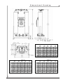
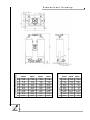
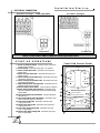
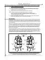
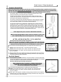
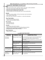
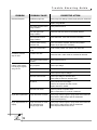
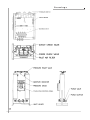
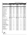
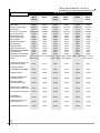
OWNERS
MANUAL
Form: F-0072
Heatless Desiccant Air Dryer
HEATLESS DESICCANT AIR DRYER
MODELS RH203-RH224
ARROW PNEUMATICS
Table
of
Contents
Unpacking/Application/Analysis
3
Specifications
4
Dimensional
Drawings
Installation
/Touch
5-6
Pad
Control
Panel
Installation/Start-up
Dryer
8
Operation
Optional
9-10
Equipment
11-12
Maintenance
Maintenance/
Trouble
13-14
Trouble
Shooting
Warranty
2
Shooting
Guide
Drawings
Replacement
7
Guide
15
16
17
Parts
18-19
20
Unpacking/Application/Analysis
READ CAREFULLY BEFORE ATTEMPTING TO INSTALL, OPERATE OR MAINTAIN YOUR
DRYER. PROTECT YOURSELF AND OTHERS BY OBSERVING ALL SAFETY
INFORMATION. FAILURE TO DO SO COULD RESULT IN PERSONAL INJURY AND/OR
PROPERTY DAMAGE. KEEP OWNER’S MANUAL FOR FUTURE REFERENCE.
UNPACKING
ARROW REGENERATIVE AIR DRYERS ARE SHIPPED AS COMPLETELY ASSEMBLED PACKAGES FILLED WITH DESICCANT READY TO INSTALL.
VISUALLY CHECK THE DRYER FOR DAMAGE THAT MAY HAVE OCCURRED IN TRANSIT. IF
THERE IS EVIDENCE OF DAMAGE, IMMEDIATELY ENTER A CLAIM WITH THE CARRIER,
AND NOTIFY YOUR ARROW REPRESENTATIVE.
APPLICATION CHECK AND ANALYSIS
TO ACHIEVE THE BEST DRYER PERFORMANCE, YOU SHOULD CAREFULLY CHECK THAT
THE DESIGN AND INSTALLATION REQUIREMENTS OUTLINED BELOW ARE SATISFIED.
1
Standard operating pressure of your Arrow Dryer can range from 75 minimum to 150 maximum
PSIG. Check dryer label to verify maximum service pressure. Air available for your air usage will
vary with operating pressure.
2
The dryer should not be installed where compressed air and/or ambient temperature exceeds
120°F or drops below 32°F. Locate dryer to avoid extremes of heat and cold from other conditions.
Best results occur when dryer is located as close to point of use as practical. Where applicable,
dryer towers should be insulated to reduce heat loss. Avoid locating dryer outside or where it is
exposed to the elements.
3
Arrow dryers are sized according to air flow not pipe size. The dryer requires 10% to 15% of inlet
airflow (SCFM) for regeneration. The difference between the inlet and outlet flow is the amount of
purge air required. This air is purged to atmosphere and is not available for use downstream.
Make certain air supply to dryer meets your air demand plus purge air requirements.
INTRODUCTION TO HEATLESS REGENERATIVE DRYING
Twin tower regenerative air dryers are the dryers of choice when traditional refrigerated dryers do not
provide sufficient air quality required for today’s applications. Arrow’s reliable ”RH” series of heatless
twin tower regenerative dryers normally produce –40°F and can optionally be as low as –100°F dew
points. The dryer utilizes activated alumina for efficient drying of compressed air and will operate
under extreme environmental conditions. Activated alumina is aluminum oxide that is highly porous
and exhibits tremendous surface area (350 sq. meters/gram). Activated alumina is resistant to thermal shock and abrasion. It has a smooth, uniform ball size that prevents channeling of the air flow,
which maintains low bed velocities. This maintains air contact time for efficient moisture removal and
minimal pressure drop. Arrow’s printed circuit board dryer controls are housed in a NEMA 4X
rated enclosure and provide control of pneumatically piloted valves chosen for long life
and high air flow.
3
Specifications
SPECIFICATIONS
Drying
Model Capacity Pipe Size Height
No.
SCFM Connection Inches
RH203
RH204
RH205
RH206
RH207
RH208
RH209
RH210
RH211
RH212
RH213
RH214
RH215
RH216
RH217
RH218
RH219
RH220
RH221
RH222
RH223
RH224
35
50
75
100
125
150
200
250
300
350
400
500
650
750
900
1,100
1,300
1,500
1,800
2,100
2,500
3,000
3/4” NPT
3/4” NPT
3/4” NPT
1” NPT
1” NPT
1-1/2” NPT
1-1/2” NPT
1-1/2” NPT
2” NPT
2” NPT
2” NPT
2” NPT
2-1/2” NPT
2-1/2” NPT
2-1/2” NPT
3” FLG
3” FLG
3” FLG
3” FLG
3” FLG
4” FLG
4” FLG
40
57
57
66
66
73
73
73
70
70
88
88
95
95
95
103
103
113
113
113
110
110
Width
Inches
31
39
39
39
39
45
45
45
51
51
52
52
60
60
60
71
71
83
83
83
95
95
Depth
Inches
18
24
24
24
24
36
36
36
36
36
36
36
36
36
36
48
48
60
60
60
60
60
Weight
Lbs.
360
508
599
627
657
739
797
855
918
1,124
1,187
1,245
1,905
2,022
2,197
2,500
3,350
3,775
4,550
5,725
6,500
8,500
Purge Flow
SCFM
4.9
7.00
10.60
14.12
17.50
21.20
28.50
35.30
42.37
48.10
56.50
70.60
88.70
105.90
127.10
155.40
183.60
211.80
254.00
297.00
353.00
424.00
ADDITIONAL SPECIFICATIONS
• Specifications and dimensions are subject to change without notice.
• Standard design conditions are 100°F inlet temperature, 100 psig and 100˚F ambient temperature. For other
than standard design conditions or capacities up to 12,000 scfm, consult your factory representative.
• Maximum pressure drop of 2 PSIG
• Maximum Working Pressure: 150 PSIG
• Minimum Working Pressure: 75 PSIG
• Maximum Inlet Temperature: 120ºF
• Minimum Inlet Temperature: 32ºF
• Standard Pressure Dew Point: -40ºF
• Electrical Construction: NEMA 4X
• Standard Voltage: 120V/1PH/60HZ
• AMPS: 0.5
4
Purge Pressure
Setting
45
45
42
60
39
50
50
45
42
50
45
38
35
44
40
40
47
55
55
43
36
46
PSIG
PSIG
PSIG
PSIG
PSIG
PSIG
PSIG
PSIG
PSIG
PSIG
PSIG
PSIG
PSIG
PSIG
PSIG
PSIG
PSIG
PSIG
PSIG
PSIG
PSIG
PSIG
Dimensional
Drawing
DIMENSIONED IN INCHES
MODEL NO.
A
B
C
D
E
F
G
H
J
K
L
M
203
39.37
6.42
31.79
0.75
29.70
31.20
15.00
18.00
1.50
0.5625
15.60
3.90
204
57.37
8.41
47.81
1.25
35.75
39.00
21.00
24.00
1.50
0.5625
19.50
3.92
209
72.78
9.73
61.32
1.25
42.25
44.75
30.00
36.00
3.00
0.8125
22.375
5.59
210
72.78
9.73
61.32
1.25
42.25
44.75
30.00
36.00
3.00
0.8125
22.375
5.59
211
69.77
9.65
57.95
1.25
48.75
51.25
30.00
36.00
3.00
0.8125
22.125
6.46
212
69.77
9.65
57.95
1.25
48.75
51.25
30.00
36.00
3.00
0.8125
22.125
6.46
DIMENSIONED IN INCHES
DIMENSIONED IN INCHES
5
208
72.78
9.73
61.32
1.25
42.25
44.75
30.00
36.00
3.00
0.8125
22.375
5.59
206
66.50
7.81
65.94
1.25
35.75
39.00
21.00
24.00
1.50
0.5625
19.50
3.98
207
66.50
7.81
65.94
1.25
35.75
39.00
21.00
24.00
1.50
0.5625
19.50
3.98
MODEL NO.
MODEL NO.
A
B
C
D
E
F
G
H
J
K
L
M
205
57.37
8.41
47.81
1.25
35.75
39.00
21.00
24.00
1.50
0.5625
19.50
3.92
A
B
C
D
E
F
G
H
J
K
L
M
213
88.27
10.65
75.45
1.25
49.00
51.50
30.00
36.00
3.00
0.8125
25.75
6.47
214
88.27
10.65
75.45
1.25
49.00
51.50
30.00
36.00
3.00
0.8125
25.75
6.47
215
95.32
12.05
80.70
1.25
57.40
59.90
30.00
36.00
3.00
0.8125
29.95
7.77
216
95.32
12.05
80.70
1.25
57.40
59.90
30.00
36.00
3.00
0.8125
29.95
7.77
217
95.32
12.11
80.64
1.25
57.40
59.90
30.00
36.00
3.00
0.8125
29.95
7.74
Dimensional
RH218
102.90
7.55
99.16
1.25
68.00
70.50
42.00
48.00
3.00
0.8125
35.25
0.8750
A
B
C
D
E
F
G
H
J
K
L
M
6
RH219
102.90
7.55
99.16
1.25
68.00
70.50
42.00
48.00
3.00
0.8125
35.25
0.8750
RH220
112.41
8.05
108.65
1.25
80.00
82.50
54.00
60.00
3.00
0.8125
41.25
0.8750
MODEL NUMBER
RH221
112.41
8.05
108.65
1.25
80.00
82.50
54.00
60.00
3.00
0.8125
41.25
0.8750
DIMENSIONED IN INCHES
DIMENSIONED IN INCHES
MODEL NUMBER
Drawing
A
B
C
D
E
F
G
H
J
K
L
M
RH222
112.41
8.05
108.65
1.25
80.00
82.50
54.00
60.00
3.00
0.8125
41.25
0.8750
RH223
110.18
7.07
105.68
1.25
92.5
95
54
60
3
0.8125
47.5
3.84
RH224
110.18
7.07
105.68
1.25
92.5
95
54
60
3
0.8125
47.5
3.84
Installation
MOUNTING SPECIFICATIONS AND DRYER LOCATION
1
Electrical connection must be hard piped with an external fused disconnect switch and
proper overload protection. See electrical connection section for connection location.
WARNING
ARROW DRYERS ARE WIRED FOR HIGH VOLTAGE. ONLY QUALIFIED ELECTRICIANS
ARE AUTHORIZED TO SERVICE THIS ELECTRICAL EQUIPMENT
2
3
4
Frame must be suitably grounded.
Generally locate your dryer downstream from the air receiver. The only exception would be
on applications with a fluctuating demand. Then the dryer should be located upstream of the
receiver to avoid air surges through the dryer’s desiccant beds.
Provide adequate space around the dryer for servicing.
Bolt dryer skid to foundation where possible.
PIPING ARRANGEMENT & FILTER INSTALLATION
1
Remove all pipe plugs from the dryer. Take care to insure that pipe dope, pipe tape,
scale or metal chips are not trapped before the inlet port.
Note: Pre & after filters must be used
on all Regenerative Air Dryers.
Note: In situations where air supply is required 24 hours a day (it is undesirable
to interrupt the airflow), a three valve bypass system is recommended to
bypass the dryer and filters. Use the fewest elbows and taper connections
necessary to keep pressure drop at a minimum.
7
2
Wet air inlet is at the dryer’s bottom piping assembly. Dry air outlet is from the dryer’s top
piping assembly (see flow diagram on page 9).
3
Install Pre-Filters to “Inlet Air” connection on the bottom piping assembly.
• Wet, compressed air should be connected to pre-filter.
• Compressed air entering the dryer must be cooled to at least 120ºF.
• Pre-filters, located before the dryer, protect desiccant beds from contamination by
oil, entrained water, pipe scale, etc., thereby extending dryer desiccant life. Locate
pre-filters as close to the dryer as possible.
• It is recommended that a mechanical separator be installed immediately preceding the
pre-filter to remove the bulk liquid oil and entrained water.
4
Install After Filter to “Outlet Air” connection on the top piping assembly.
• Dry, service air should be connected to after-filter.
• After filters, located after the dryer, help eliminate the possibility of desiccant dusting
and carry over into the air system.
Installation/Start-up
ELECTRICAL CONNECTION
Standard Voltage - 120V/1ph/60Hz
All Other Voltages
Customer Hook-Up
Customer Hook-Up
Note: Circuit Board Timer is rated for 120V/1ph/60Hz ONLY
START-UP
OPERATIONS
Touch Pad Control Panel
1. Power On/Off Push Button - Energizes circuit board timer,
initiating dryer operation.
2. Power ON LED - Illuminates when dryer is in operation.
3. Failure to Shift Alarm LED - Illuminates when dryer has
failed to shift.
4. Failure to Purge Alarm LED - Illuminates when dryer has
failed to purge.
5. Failure to Repressurize Alarm LED - Illuminates when dryer
has failed to repressurize.
6. Failure to Depressurize Alarm LED - Illuminates when dryer
has failed to depressurize.
7. High Humidity Alarm LED (Optional) - Illuminates when an
elevated dew point has occurred.
8. Alarm Condition Reset Button - Clears all alarms conditions
9. Energy Savings Mode LED (Optional) - Illuminates when
dryer has reached the desired dew point and initiates Energy
Savings Mode.
10. Dew Point Demand On/Off Button - Energizes Dewpoint
Demand Logic.
11. Dew Point Demand LED (OPTIONAL) - Illuminates when
Dewpoint Demand Logic is in operation.
12. Left Tower Drying LED - Illuminates when left tower
is drying service air.
13. Right Tower Drying LED - Illuminates when right tower
is drying service air.
14. Left Tower Regenerating LED - Illuminates when left
tower is regenerating.
15. Right Tower Regenerating LED - Illuminates when right
tower is regenerating.
8
OUTLET
12
14
LEFT
TOWER
RIGHT
TOWER
DRYING
DRYING
REGENERATING
REGENERATING
13
15
9
INLET
DEWPOINT DEMAND SYSTEM
11
10
ENERGY SAVINGS MODE
ON/OFF
DEW POINT DEMAND (OPTIONAL)
5
6
ALARM CONDITIONS
PURGE
REPRESSURIZE
SHIFT
DEPRESSURIZE
4
8
RESET
HIGH HUMIDITY
(OPTIONAL)
7
3
POWER
2
ON/OFF
1
Dryer
Operation
AFTER ALL PIPING AND ELECTRICAL CONNECTIONS ARE MADE, PROCEED AS FOLLOWS:
1
2
SLOWLY PRESSURIZE THE DRYER!
When the dryer reaches full operating pressure, check the system for air leaks. Soap test
all joints and fittings. To maintain desired dew point, any leaks detected must be fixed,
especially those on the outlet side of the dryer.
3
Energize electrical circuit by simply pressing the power on/off button.
4
The Power On LED will be illuminated when the dryer is in operation.
When the electrical circuit has been energized, the control circuit board will
start to operate and automatically initiate dryer operation. The timer is factory set,
so that no field adjustment is necessary.
5
Adjust purge adjustment valve so that the center purge pressure gauge reads appropriate
pressure (see specifications chart for purge pressure on page 2).
Dryer Operation
Compressed air saturated with water vapor passes through the inlet valve and flows upward through
the desiccant in tower “A”. Tower “A” is said to be “on line”. The activated alumina desiccant adsorbs
the water vapor in the compressed air and the pressure dew point is lowered to a minimum of –40°F.
The dried air then passes through a check valve assembly to the outlet piping and then to the factory
tools or equipment.
While the air is being dried in tower “A”, the desiccant in tower “B” that adsorbed moisture in the previous cycle is simultaneously regenerated. Tower “B” is “off line”. At the start of the regeneration cycle,
tower “B” is depressurized from the operating pressure to atmospheric pressure with a downward air
flow and passes through the purge valve and out the purge muffler. Regeneration continues with a
portion of the dry air from tower “A” passing through an orifice assembly and downward through
tower “B” out to atmosphere.
This process takes about ten minutes to complete, with the drying cycle using about five minutes to
provide the desired dew point. The regeneration cycle takes approximately 45 seconds less to allow for
repressurization before switchover. The complete operation therefore consists of two cycles, one for
drying and the other for regeneration. Required purge air is generally 15% of rated flow. As pressure
is a direct function of purge air, the higher the pressure, the lower the purge.
LEFT TOWER "A"
"Off-Line"
Regenerating
LEFT TOWER "A"
"On-Line"
Drying
9
RIGHT TOWER "B"
"On-Line"
Drying
RIGHT TOWER "B"
"Off-Line"
Regenerating
REGENERATING FLOW
REGENERATING FLOW
DRYING FLOW
DRYING FLOW
NOTE: At Initial Start-Up, check the dryer operation for one or two cycles, especially at the time
of the tower shift. Verify that all systems are operating in their proper order and sequence.
If the dryer is not functioning properly, contact your Arrow Representative.
Dryer
Operation
DRYER OPERATION cont’d
Cycle Timing
5 Min
0 Min
10 Min
Right Normally Open Inlet Valve
4:15 min.
15 sec.
Right Normally Closed Purge Valve
Left Normally Open Inlet Valve
5:15 min.
9:15 min.
Left Normally Closed Purge Valve
Closed
Open
Moisture Indicator
The Moisture Indicator is located in the top center piping. The Moisture indicator is provided to
warn operating personnel of dryer malfunction. If the dryer is functioning properly, the desiccant in
the Moisture Indicator will be blue. Should the blue color fade or turn pink, discontinue dryer use
and refer to elevated dew point section in Troubleshooting Guide.
Note: A small portion of air should flow
through the moisture indicator
Pressure Alarm Package
The pressure alarm package is designed to monitor the following: Depressurization and repressurization
of towers, purge pressure and tower shifting.
Failure to Depressurize – Senses for pressure on the offline tower after tank shift-over. Should the
tower fail to depressurize do to a malfunctioning system component (i.e. purge valve, solenoid valve,
purge check valve or circuit board timer) the Failure to Depressurize LED will be illuminated. The Failure
to Shift LED will also be illuminated to show a shift failure. Should the alarm LED be observed, refer to
Troubleshooting Guide.
Failure to Repressurize – Senses for pressure on the offline tower before tank shift-over. Should the
tower fail to repressurize do to a malfunctioning system component (i.e. purge valve, solenoid valve, or
circuit board timer) the Failure to Repressurize LED will be illuminated. The Failure to Shift LED will also
be illuminated to show a shift failure. Should alarm LED be observed, refer to Troubleshooting Guide.
Failure to Purge – Senses for pressure on the center purge piping at all times during dryer operation.
Should a low purge pressure condition occur (i.e. purge flow regulator turned down or debris in the
purge pressure piping) the Failure to Purge LED will be illuminated. Should alarm LED be observed, refer
to Troubleshooting Guide.
Failure to Shift – The Failure to Shift LED will be illuminated when a dryer shift failure has occurred.
The shift failure was due to a Failure to Depressurize or Failure to Repressurize. Observe dryer operation
to determine which failure caused the Failure to Shift and refer to Troubleshooting Guide.
10
Optional
Equipment
Dewpoint Demand Plus
NOTE: At initial startup and during the first six months of continuous dryer operation, the Dew Point
Demand Plus logic SHOULD NOT BE ACTIVATED. A conditioning process must occur in new desiccant,
this will allow the desiccant to remove its precise water vapor capacity from the airflow.
The function of DDP is to conserve energy by eliminating unnecessary dryer cycling,
purge air consumption, and compressor power consumption.
The DDP works by utilizing a moisture sensitive probe to measure the water vapor
content of the outlet air flow. The moisture content of the sample air stream indicates
the wetness of the drying tower’s desiccant bed.
The purpose of the probe and its associated electronics is to first measure the “wetness”
of the air within the desiccant beds and then regenerate the desiccant beds only when
the moisture loading reaches a pre-set maximum, desired dewpoint.
The Dew Point Demand Plus is packaged with a digital dew point controller and High
Humidity Alarm option. The digital dew point controller allows the end user to pre-set a
desired dew point at which the dryer will start the Energy Savings Mode. This controller
also allows the end-user to pre-set a dew point at which a high humidity alarm condition
would occur. See High Humidity Alarm option for full description. See the digital dew point
controller Owners Manual enclosed for changing desired dew points.
1
NOTE: Digital dew point controller UNLOCKING CODE 430.
2
NOTE: Energy Savings Mode is factory preset to activate at -30º F dew
point. High Humidity alarm is factory preset to +10º F dew point.
AFTER APPROXIMATELY SIX MONTHS
NOTE: Factory Shipped With Dew
Point Demand Logic Turned Off and
DDP Sample Valve 1 and 2 closed.
Dew Point Demand System Startup and Operation
NOTE: Allow the dryer to operate for a number of cycles to ensure that the probe
will not be exposed to high humidity and damaging liquid water. This is especially
important when the dryer has been stored or sitting idle for several months.
1
Press the Dew Point Demand ON/OFF button to energize Dew Point Demand Logic.
2
Slowly open the DDP sample valve1. This valve should be fully opened.
3
Slowly open the DDP sample valve2 so that a small flow of air passes across the
probe (approximately 2 to 3 SCFH). This valve should be open at all times when
dryer is in operation.
OUTLET
DEWPOINT DEMAND SYSTEM
ENERGY SAVINGS MODE
ON/OFF
4
DEW POINT DEMAND (OPTIONAL)
ALARM CONDITIONS
PURGE
REPRESSURIZE
HEATER OVERTEMP
(OPTIONAL)
S
When the desired dew point is reached, the energy savings mode LED will be energized to
indicate the dryer is in energy savings mode; eliminating unnecessary dryer cycling, purge
air flow and compressor power consumption.
Dew Point Demand
Dew Point Demand is a cost effective alternative to Dew Point Demand Plus. This system operates similar
to the Dew Point Demand Plus, but does not have the digital display, high humidity alarm or an adjustable
dew point “tank switchover”. The “tank switchover” occurs at a fixed –40˚F dew point.
Dew Point Demand System Startup and Operation
NOTE: Allowing the dryer to operate for a number of cycles ensures
that the probe will not be exposed to high humidity and damaging
liquid water. This is especially important when the dryer has
been stored or sitting idle for several months.
1
Press the Dew point ON/OFF button to energize Dew Point Demand Logic
2
Slowly open the DDP sample valve1 so that a small flow of air passes across the
probe (approximately 2 to 3 SCFH). This valve should be open at all times when
dryer is in operation.
3
11
When “fixed” -40ºF dewpoint is reached, the energy savings mode LED will be energized to
indicate the dryer is in energy savings mode; eliminating unnecessary dryer cycling, purge
air flow and compressor power consumption.
1
NOTE: Factory Shipped With Dew Point Demand
Logic Turned Off and DDS Sample Valve 1 closed.
Optional
Equipment
cont’d
High Humidity Alarm: This option continuously monitors the outlet air stream for dew point performance. Should the dryer dew
point elevate because of malfunctioning system component, overflow condition, oil contamination or desiccant attrition, the High
Humidity Alarm LED will be illuminated. Should the light be observed, refer to Troubleshooting Guide.
–100˚F Pressure Dew Point: This option lowers the outlet dew point from the standard –40˚F to –100˚ F. The cycling time is
adjusted accordingly and a repressurizing system is added. The cycle time will be adjusted from a five minute cycle, 2-1/2 minutes
each tower. A normally closed valve will be added to the upper center piping to assist repressurizing each tower.
2.30 Min
0 Min
5 Min
Right Normally Open Inlet Valve
2:15 min.
15 sec.
Right Normally Closed Purge Valve
Left Normally Open Inlet Valve
2:45 min.
4:45 min.
Left Normally Closed Purge Valve
2:15 min.
Normally Closed
Repressurization Valve
4:45 min.
Closed
Open
Remote Alarm Contacts: Contacts will be supplied for: Energy Saving Mode, High Humidity Alarm, Failure to Depressurize alarm,
Failure to Repressurize, Failure to Purge and Failure to Shift, allowing an easy connection method for energizing remote visual or
audible alarms. A 120-volt signal is sent when a failure occurs. (Refer to attached diagram.)
Remote Alarm Dry Contacts: Contacts will be supplied for: Energy Saving Mode, High Humidity Alarm, Failure to Repressurize,
Failure to Depressurize alarm, Failure to Purge and Failure to Shift, allowing for Customer supplied alarm circuits to be easily
connected. Maximum voltage and current is 120V, 3 amperes.(Refer to attached diagram.)
Low Ambient Package: Low ambient temperature protection is accomplished by encasing both towers with a rugged insulation.
This insulation along with heat trace cables eliminates “freeze-ups” from low ambient conditions such as cold outdoor or unheated
indoor installations.
1
Check to see that the power supply to the heat trace cable is 120V.
2
Install the power cord plug into receptacle.
RS-232 Serial Communications Interface: Allows serial port connections for computer monitoring of dryer functions and
operating statuses. (Refer to attached diagram.)
1
Pre-piped Connection With Pre and After Filters1
Prefilter and afterfilter mounted to dryer with integral piping ready to install in system.
2
3-Valve Bypass w/Pre-piped Connection2
Prefilter and afterfilter mounted to dryer with integral piping and 3 bypass valves for bypassing filters
and dryer. Ready to install in system.
7-Valve Bypass w/Pre-piped Connection3
Prefilter and afterfilter mounted to dryer with integral piping and 7 bypass valves for individually
bypassing either filter and/or dryer. Ready to install in system.
12
3
Maintenance
WARNING:
BEFORE MAINTENANCE OF DRYER ALWAYS SHUT DRYER OFF,
DISCONNECT THE ELECTRICAL SUPPLY, AND DEPRESSURIZE
THE PNEUMATIC SYSTEM TO AVOID PERSONAL INJURY
Prefilters and Afterfilters
Note: For maximum filtration efficiency service elements and
drains according to manufacturer’s recommended schedule.
Solenoid Valves
Periodically clean entire solenoid valve block. If any of the normally closed solenoid valves fail to
operate, use the air flow diagram below to check operation, and then check the following:
1. Control Voltage - Check the outlet voltage sequence from the circuit board to verify that
the solenoid is receiving electric voltage.
2. Burned out solenoid cell
3. High/low voltage - Voltage should be plus or minus 10% of nameplate reading.
4. Solenoid valve leaking - Disassemble, clean and repack or replace.
Timer
Should the sequencing of towers fail, first check the red light marked “Status” located on the timer
circuit board. When blinking, the timer board is energized. If the light is not blinking, check the
voltage across the 3 Amp 3 AG fuse located on the board. Replace fuse if “blown”. If fuse is not
“blown” check voltage sequence to the appropriate solenoid valve.
VOLTAGE SEQUENCE
5 Min
0 Min
10 Min
Right N.O. Inlet Valve J5 Pin #4
4:15 min.
15 sec.
Right N.C. Inlet Valve J5 Pin #3
Left N.O. Inlet Valve J5 Pin #9
5:15 min.
Left N.C. Inlet Valve J5 Pin #8
120 Voltage
0 Voltage
13
9:15 min.
Maintenance
cont’d
WARNING
WHEN REPLACING THE PURGE MUFFLERS IT IS RECOMMENDED THE DRYER BE TURNED
OFF AND FULLY DEPRESSURIZED. BACKPRESSURE CAUSED BY CLOGGED MUFFLER CAN
CAUSE INJURY SHOULD YOU ATTEMPT TO DISASSEMBLE WHILE PRESSURIZED.
Purge Muffler
At high pressures a clogged muffler could result in a high backpressure and could result in mechanical failure
or personal injury. For this reason the purge muffler must be periodically checked for any restrictive debris. If
pressure is observed on the offline tower replace muffler immediately.
PREVENTATIVE MAINTENANCE
WARNING
TO AVOID INJURY, DEPRESSURIZE DRYER BEFORE PERFORMING ANY SERVICE
Purge Valve
Should either of the normally closed purge valves fail to operate check the following:
1. Check air signal to valve.
• If air signal is present; disassemble, clean and replace diaphragm and seals.
• If no air signal is present; see solenoid valve information in Maintenance Section.
Inlet Valve
Should either of the normally open inlet valves fail to operate check the following:
2. Check air signal to valve.
• If air signal is present; disassemble, clean and replace diaphragm and seals.
• If no air signal is present; see solenoid valve information in Maintenance Section.
Outlet and Purge Check Valves
NOTE: Signs of a faulty outlet and/or purge check valve include;
• Failure to Depressurize Alarm
• System air is being drained and compressor is running at below normal efficiency.
Periodically check the outlet and purge check valves for an absolute seal.
Procedure:
1. Close purge adjustment valve. Verify offline tower pressure is 0 PSIG.
2. Check offline purge muffler for airflow. No airflow should be present.
• If no airflow is present, the outlet and purge check valve have a positive seal.
Repeat procedure next cycle to check opposite outlet and purge check valves.
• If airflow is present, the outlet and/or purge check valves do not have a positive seal. Clean
and/or replace corresponding check valves. See air flow diagram for corresponding check valves.
Pilot Air Filter
For maximum filtration efficiency, service the element 3 times a year and replace yearly.
14
Maintenance/
Trouble
Shooting
Guide
PREVENTATIVE MAINTENANCE SCHEDULE cont’d
Daily
1.
2.
3.
4.
5.
Check and record inlet pressure, temperature and flow. Verify that it is within specifications.
Check tower pressure gauge readings within operating tolerance.
Check tower pressure gauges for proper dryer cycling .
Verify that pressure in purging tower is 5 PSIG or less.
Verify that prefilters and off-line differential pressure is within operating limits.
Monthly
1. Check your operating conditions: inlet flow, inlet pressure, and inlet temperature.
2. Check prefilters and after filters.
3. Check dryer cycle and sequence of operations, (i.e. drying and regenerating).
Every Three Months
1. Check pilot air filter element and clean.
2. Replace prefilter and afterfilter elements.
Semi-Annually
1. Check outlet dew point.
2. Blow down relief valves.
Annually
1.
2.
3.
4.
Check desiccant and replace if necessary.
Inspect and clean pilot operated valves and replace packing as necessary.
Inspect and clean solenoid valves, check valves and purge lines.
Test electrical components, replace as necessary.
Every Three Years
1. Replace desiccant if necessary.
TROUBLE SHOOTING GUIDE
PROBABLE CAUSE
CORRECTIVE ACTION
Purge valve does not open
Check purge valve,air signal to valve and its solenoid valve.
Refer to earlier steps if pilot air is detected. Refer to
Preventative Maintenance (PM) Section. Check timer voltage
sequencing.
Purge muffler is clogged
Replace Purge Muffler.
Purge Check Valve
stuck open
See outlet/purge check valve PM section
for positive seal.
Outlet check valve
stuck open
See outlet/purge check valve PM section
for positive seal.
Excessive back pressure in regenerating
tower (above 5PSIG)
Purge muffler is clogged
Replace purge muffler.
Outlet check valve stuck
open
Clean and/or replace valve.
System air
being drained
Outlet and/or purge check
valve stuck open
See outlet/purge check valve PM section
for positive seal.
PROBLEM
Dryer fails to
depressurize
15
Trouble
PROBLEM
PROBABLE CAUSE
Shooting
Guide
CORRECTIVE ACTION
Insufficient purge rate
Check purge flow settings. Check purge piping for obstruction.
Clogged Purge Muffler
Replace Purge Muffler.
Inlet air/gas pressure below
design condition
Check pressure source.
Flow rate higher than
design condition
Check flow rate and causes for increased demand.
Inlet temperature above
design condition
Check aftercooler, clean and service as necessary.
Entrained water entering
desiccant bed
Check air/moisture separator, elements and prefilter.
Replace dryer desiccant if necessary.
Desiccant contaminated
by oil
Install suitable prefilter and replace dryer desiccant.
Excessive flow rate
Check flow rate. Locate cause for increased air demand.
Inlet pressure below design
condition
Check pressure source.
No input power
Check input voltage.
Dryer not turned on
Check power on LED.
Defective timer
Check input and output voltages.
Defective solenoid valve
Check input voltage to solenoid valve.
Check outlet air flow from solenoid valve.
No pilot air
Check pilot air-line for blockage
Check to see if pilot air-line filter is clean.
Replace element if needed.
Defective inlet valves
Check for pilot air to operate valve.
Refer to steps above if no pilot air is detected.
Dryer fails to pressurize
Purge Valve does not close
Check purge valve,air signal to purge valve and its solenoid
valve. Refer to earlier steps if pilot air is detected.
Check timer sequencing.
Dryer depressurizes too
rapidly
Purge valve does not close;
dryer depressurizing
through purge valve
Check purge valve,air signal to purge valve and its solenoid
valve. Refer to earlier steps if pilot air is detected.
Check depressurization timer circuit.
Elevated Dewpoint
Excessive pressure
drop in dryer
Failure to shift towers
from drying to regenerating service
16
Drawings
17
Replacement
M O D E L
Part Description
RH203
RH206
RH208
RH211
RH213
RH204
RH207
RH209
RH212
RH214
RH205
INLET VALVE
REPAIR KIT (INLET VALVE)
PURGE VALVE
(REPAIR KIT) PURGE VALVE
OUTLET CHECK VALVE
Parts
RH210
126150
126155
126156
126157
126157
126150-RK
126155-RK
126156-RK
126157-RK
126157-RK
126151
126151
126151
126151
126154
126151/54-RK
126151/54-RK
126151/54-RK
126151/54-RK
126151/54-RK
25526
25527
126167
126168
126168
PURGE CHECK VALVE
122028
122091
25526
25526
25527
CIRCUIT BOARD TIMER
126719
126719
126719
126719
126719
PANEL OVERLAY
126530
126530
126530
126530
126530
SOLENOID VALVE BLOCK
126183
126183
126183
126183
126183
PURGE MUFFLER
126060
126060
126061
126061
126039
PRESSURE GAUGE
122150
122150
122150
122150
122150
PRESSURE RELIEF VALVE
122050
122050
122050
122051
126026
MOISTURE INDICATOR
ASSEMBLY
PILOT AIR FILTER
126502
9052T
126502
9052T
126502
9052T
126502
9052T
126502
9052T
(ELEMENT KIT)
PILOT AIR FILTER
EK9052
EK9052
EK9052
EK9052
EK9052
RH203: 42 lbs
RH204: 58 lbs
RH205: 88 lbs
RH206: 116 lbs
RH207: 146 lbs
RH208: 174 lbs
RH209: 232 lbs
RH210: 290 lbs
RH211: 348 lbs
RH212: 406 lbs
RH213: 464 lbs
RH214: 580 lbs
ACTIVATED ALUMINA 400 LBS.
FIBER DRUM 1/8" BEADS
34010
34010
34010
34010
34010
ACTIVATED ALUMINA
50 LBS. FIBER DRUM 1/8” BEADS
34011
34011
34011
34011
34011
PRESSURE SWITCH
122245
122245
122245
122245
122245
DEWPOINT DEMAND
PLUS SENSOR (OPT)
126048
126048
126048
126048
126048
DEWPOINT DEMAND
PLUS CONTROLLER (OPT)
126536
126536
126536
126536
126536
CIRCUIT BOARD - DEWPOINT
DEMAND/HIGH HUMIDITY (OPT))
122717
122717
122717
122717
122717
HIGH HUMIDITY SENSOR (OPT)
123079
123079
123079
123079
123079
DEWPOINT DEMAND
SENSOR (OPT)
122158
122158
122158
122158
122158
TRANSFORMER
230V & 480V (OPT)
122297
122297
122297
122297
122297
TRANSFORMER 380V, 440V,
550V, & 600V (OPT)
122335
122335
122335
122335
122335
REPRESSURIZING VALVE
122223
122223
122223
122223
122223
REPLACEMENT DESICCANT
(TOTAL)
18
Replacement
Parts
M O D E L
Part Description
RH215
RH217
RH216
INLET VALVE
REPAIR KIT (INLET VALVE)
PURGE VALVE
(REPAIR KIT) PURGE VALVE
RH218
RH220
RH219
RH221
RH222
RH223
RH224
126862
126862
126227
126227
126227
126201
126862-RK
126862-RK
126227-RK
126227-RK
126227-RK
126201-RK
126154
126161
122136
122136
12775
126776
126151/54-RK
126161-RK
122136-RK
122136-RK
12775-RK
126776-RK
OUTLET CHECK VALVE
126859
126859
126228
126228
126228
126166
PURGE CHECK VALVE
25527
126575
126167
126167
126167
126168
CIRCUIT BOARD TIMER
126719
126719
126719
126719
126719
126719
PANEL OVERLAY
126530
126530
126530
126530
126530
126530
SOLENOID VALVE BLOCK
126183
126183
126183
126183
126183
126183
PURGE MUFFLER
126039
126214
126214
126214
126214
126214
PRESSURE GAUGE
122150
122150
122150
122150
122150
122150
PRESSURE RELIEF VALVE
122076
122076
122053
122053
122053
126113
MOISTURE INDICATOR ASSEMBLY
126502
126502
126502
126502
126502
126502
PILOT AIR FILTER
9052T
9052T
9052T
9052T
9052T
9052T
EK9052
EK9052
EK9052
EK9052
(ELEMENT KIT) PILOT AIR FILTER
EK9052
EK9052
REPLACEMENT DESICCANT
RH215: 754 lbs
RH217: 1044 lbs RH218: 1276 lbs
RH220: 1740 lbs
RH222: 2436 lbs RH223: 2750 lbs
(TOTAL)
RH216: 870 lbs
RH219: 1508 lbs
RH221: 2088 lbs
RH224: 3300 lbs
ACTIVATED ALUMINA 400 LBS.
FIBER DRUM 1/8" BEADS
34010
34010
34010
34010
34010
34010
ACTIVATED ALUMINA
50 LBS. FIBER DRUM 1/8" BEADS
34011
34011
34011
34011
34011
34011
PRESSURE SWITCH
122245
122245
122245
122245
122245
122245
DEWPOINT DEMAND126048
PLUS SENSOR (OPT)
126048
126048
126048
126048
126048
126048
DEWPOINT DEMAND
PLUS CONTROLLER (OPT)
126536
126536
126536
126536
126536
126536
CIRCUIT BOARD - DEWPOINT
DEMAND/HIGH HUMIDITY (OPT)
122717
122717
122717
122717
122717
122717
HIGH HUMIDITY SENSOR (OPT)
123079
123079
123079
123079
123079
123079
TRANSFORMER
(230V & 480V OPT)
122297
122297
122297
122297
122297
122297
TRANSFORMER (380V, 440V,
550V, & 600V OPT)
122335
122335
122335
122335
122335
122335
REPRESSURIZATION VALVE (OPT.)
122223
122223
122223
122223
122223
+122223
19
Warranty
The Arrow Regenerative type compressed air dryer is warranted to be free from
defects in material and workmanship, when used under conditions recommended by
the manufacturer, for a period of 12 (twelve) months from date of shipment from
factory to job site of original owner. Products purchased from warehouse stock are
warranted for a period of 12 (twelve) months from date of shipment from that
warehouse provided Arrow is furnished full name, address and date of shipment
information.
This warranty is limited to parts and labor F.O.B. factory, and is subject to the same
restrictions as outlined below concerning misuse, abuse or accident.
This warranty will apply to equipment installed, operated, and maintained in
accordance with the procedures and recommendations as outlined in the owners
manual published by Arrow Pneumatics.
During the life of this warranty, Arrow Pneumatics will repair or replace (at Arrow’s
option) free of charge, F.O.B. its plant, any defective part of assembly, if such defect
occurred in normal service and was not due to apparent misuse, abuse, or accident.
Any warranty service performed in the field must be authorized by Arrow
Pneumatics. Unauthorized service voids the warranty and resulting charge will not
be paid by Arrow Pneumatics.
Arrow Pneumatics makes no other warranties or guarantees, expressed or implied.
The merchantability of the components is expressly excluded. The manufacturer
assumes no liability for indirect or consequential damage.
(This warranty good only in the continental boundary of the United States. For export, contact the factory)
For Your Records
Record the serial number, found on the front of your dryer and inside the electrical
enclosure, in the spaces designated on the warranty card, and in the spaces
provided below. Refer to the model and serial number whenever you call your
distributor for information or service on this product.
Model
Serial Number
Arrow Pneumatics, Inc. 2111 W. 21st Street Broadview, Illinois 60155-4627
TEL: 708-343-9595 FAX: 708-343-1907
www.arrowpneumatics.com


![Electrolux Lux 7000 Bagged Canister Vacuum - C:\Users\Jason&Kim\Desktop\Lux7000[1]](http://vs1.manualzilla.com/store/data/007257175_1-4f8df6fa53bec1c3cae9b6f5e2e6b2de-150x150.png)