1
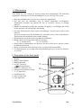
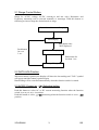
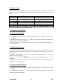
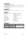
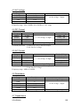
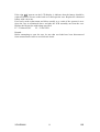
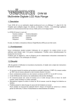
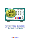
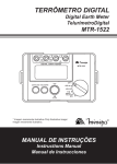
DVM 68 LCD Auto Range Digital Multimeter OPERATION MANUAL GEBRUIKERSHANDLEIDING MANUEL D’UTILISATEUR DVM 68 LCD Auto Range Digital Multimeter 1. Description Your DVM 68 is a autoranging professional digital multimeter with a 3 ¾ digit LCD display. It is ideally suited for field, lab, shop, and home applications. By using the latest in IC and display technology to significantly reduce the number of discrete internal components, the multimeter gives you superb measuring capability as well as the highest possible reliability. It is capable of performing functions : DC Voltage AC Voltage Resistance AC Current DC Current Capacity Frequency Continuity Also diodes and transistors (amplification hFE) can be tested. 1.1 Warning Use extreme caution in the use of this device. Improper use of this device can result in injury or death. Follow all safeguards suggested in this owner's manual in addition to normal safety precautions in dealing with electrical circuits. Do not use this device if you are unfamiliar with electrical circuits and testing procedures. Not for commercial or industrial use. 1.2 A word about safety This multimeter is designed to ensure the safest operation possible. However, safe operation depends on you, the operator. Make sure you follow these simple safety rules : • Never apply a voltage to the multimeter that exceeds the limits given in the specifications. Never apply more than 1000V DC or 750V rms AC between an input jack and ground. • Use extreme caution when working with voltages above 60V DC or 30V AC rms. • Always discharge filter capacitors in the power supply circuit under test before you attach test leads. • Never connect to a source of voltage when you select DCA, ACA, resistance measurement or continuity check function. • Always turn off power and disconnect the test leads before you replace the batteries or fuse. • Never operate the multimeter unless the battery cover is in place and fully closed. When carrying out measurements on TV or switching power circuits, always remember that there may be high amplitude voltages pulses at test points which can damage the meter. VELLEMAN 1 GB 1.3 Maintenance Your DVM 68 is an example of superior design and craftsmanship. The following suggestions will help you care for the multimeter so you can enjoy it for years : • Keep the multimeter dry. If it gets wet, wipe it dry immediately. • Use and store the multimeter only in normal temperature environments. Temperature extremes can shorten the life of electronic devices or damage batteries. • Handle the multimeter gently and carefully. Dropping it can damage the circuit boards and case and can improper functioning. • Use only fresh batteries of the required size and type. Always remove old or weak batteries. If you do not plan to use the multimeter for a month or more, remove the batteries. This protects the multimeter from possible leakage. • Disconnect the test probes before opening the multimeter. • Replace blown fuses only with same size and type : F1 : F 300mA/250V F2 : F 10A/250V • If any faults or abnormalities are observed, do not use this device and let it check by authorised personel. • Never use the meter unless the back cover is in place and fastened fully. • To clean the meter, use a damp cloth and mild detergent only, do not use abrasives or solvents. 2. Description of the front panel 1. 2. 3. 4. Display Range Control Button Data Hold button AC/DC Current of / Selecting Button 5. Socket for Transistor Test 6. Function Switch/Power Switch 7. V/Ω/F Input Jack 8. COM Input Jack 9. mA/Cx Input Jack 10. 10A Input Jack ÷ ô û ø í ê î ü VELLEMAN 2 ù GB 2.1 Range Control Button Range for AC/DC voltage, AC/DC current(µA and mA only), Resistance and Frequency measuring can be selected manually or autorange. Push this button as following to choose range the desired mode or range. Power On or Function Changing AutoRanging Push button once "R-H"displayed Push button for over 3 sec. Manual Ranging Push button for less than 1 sec. Range Changed 2.2 DATA HOLD button When this button is pushed, the display will show the last reading and " D-H " symbol will appear until the button is pushed again. Data holding will be cancelled automatically when the function switch is rotated. 2.3 AC/DC Current or / Selecting button Push this button to select AC or DC current measuring function when the function switch is set at µA, mA, A positions. Push this button to select or measuring when the function switch is set at / position. VELLEMAN 3 GB 2.4 Input Jacks This meter has four input jacks that are protected against overload to the limits. During use, connect the black test lead to the COM jack and the red test lead as shown below Function Red Lead Connection DCV / ACV V/Ω/F kHz V/Ω/F V/Ω/F Ω/ / µA / mA mA / Cx nF / µF mA / Cx A A µA/ mA and A ranges are protected by fuses. Input Limits 1000V DC or 750V AC rms 250V DC or AC rms 250V DC or AC rms 300mA DC or AC rms 300mA fuse protected 10A DC or AC rms 3. Operating instructions 3.1 Measuring Voltage 1) Connect the black test lead (-) to the COM jack and the red test lead (+) to the V/Ω/F jack. 2) Set the function switch at V or V∼ range to be used and connect test leads across the source or load under measurement. 3) Read LCD display. The polarity of red connection will be indicated when making a DC measurement. 3.2 Measuring Current 1) Connect the black test lead (-) to the COM jack and the red test lead (+) to the mA/Cx jack for a maximum of 300mA. For a maximum of 10A, move the red lead to the A jack. 2) Set the function switch at µA, mA or A range to be used and push / ∼ button to select DCA or ACA mode. 3) Connect test leads IN SERIES with the load in which the current is to be measured. 4) Read LCD display. The polarity of red lead connection will be indicated when making a DC measurement. 3.3 Measuring Resistance 1) Connect the black test lead (-) to the COM jack and the red test lead (+) to the V/Ω/F jack. 2) Set the function switch at Ω range to be used and connect test leads across the resistance under measurement. VELLEMAN 4 GB Remarks : 1) For resistance above 3.26MΩ, it may take a few seconds to stabilize reading. This is normal for high resistance measuring. 2) When the input is not connected, i.e. at open circuit, the figure "OL" will be displayed for the overrange condition. 3) When checking in-circuit resistance, be sure the circuit under test has all power removed and all capacitors are fully discharged. 3.4 Measuring Capacitance 1) Connect the black test lead (-) to the COM jack and the red test lead (+) to the mA/Cx jack. 2) Set the function switch at nF or µF position to be used. 3) Connect test leads across the capacitor under measurement and be sure that the polarity of connection is observed. Remarks : 1) When checking in-circuit capacitance, be sure that the circuit has all power removed and all capacitor are fully discharged. 2) The range control mode in capacitance measurement is manual ranging and only two ranges (326nF, 32.6µF) are provided. 3) If Range Control Button is used in this measuring function, decimal points may be at incorrect positions. 4) At the nF range, when the capacitor to be measured is not connected to test leads, the LCD may not read zero, but a few counts. These count have to be substracted from measuring results. 3.5 Measuring Frequency 1) Connect the black test lead (-) to the COM jack and the red test lead (+) to the V/Ω/F jack. 2) Set the function switch at the Hz position and connect test leads across the source or load under measurement. Remark : The input voltage should be between 200mV and 10V rms AC. If the voltage is more than 10V rms, reading may be out of the accuracy range. 3.6 Continuity & Diode Test 1) Connect the black test lead to the COM jack and the red test lead to the V/Ω/F jack. / position and push the / button to select 2) Set the function switch at continuity or diode test mode. 3) In continuity testing, if continuity exists (i.e. resistance less than about 50Ω), builtin buzzer will sound. 4) If diode test mode is selected, connect the red and black to the anode and cathode of the diode under test. The forward voltage drop of this diode in V will be displayed. VELLEMAN 5 GB 3.7 Transistor Test 1) Set the function switch at hFE position. 2) Identify whether the transistor is NPN or PNP type and locate emitter, base and collector lead. Insert leads of the transistor to be tested into proper holes of the testing socket on the front panel. 3) LCD display will show the approximate hFE value at the test condition of base current 10 µA and Vce 3.2V. 4. Specifications Accuracy is specified for a period of one year after calibration and at 18°C to 28°C with relative humidity to 80%. 4.1 General Max. voltage between terminal and earth Display Fuse protection Power Supply Ranging method Polarity indication Overrange indication Low Battery indication Operating temperature Storage temperature Dimensions Weight 1000V DC or 750V AC rms (sinus) 3 ¾ digit LCD, 3260 counts max, 2-3 readings / sec µA & mA range : F 300mA/250V A range : F 10A/250V 9V battery Auto / Manual " - " displayed " OL " displayed automatically " " displayed 0°C to 40°C -10°C to 50°C 91 x 189 x 31.5 mm 310 g (incl. battery) 4.2 DC Voltage Range Resolution Accuracy 326mV 0.1mV ± 0.5% of rdg ± 2 digits 3.26V 1mV 32.6V 10mV ± 0.3% of rdg ± 2 digits 326V 0.1V 1000V 1V ± 0.5% of rdg ± 2 digits Input impedance : 10MΩ, more than 100MΩ at 326mV range VELLEMAN 6 GB 4.3 AC Voltage Range Resolution Accuracy 3.26V 1mV 32.6V 10mV ± 0.8% of rdg ± 3 digits 326V 0.1V 750V 1V Input impedance : 10MΩ Frequency range : 40 to 1000Hz, 40 to 200Hz at 3.26V range 4.4 DC Current Range Resolution Accuracy 326µA 0.1µA 3260µA 1µA ± 1.2% of rdg ± 3 digits 32.6mA 10µA 326mA 0.1mA 10A 10mA ± 2.0% of rdg ± 5 digits Overload protection : F 300mA fuse for µA and mA ranges, F 10A fuse for A range Burden Voltage 0.5mV / µA 0.5mV / µA 8.0mV / mA 8.0mV / mA 0.02V / A 4.5 AC Current Range Resolution Accuracy 326µA 0.1µA 3260µA 1µA ± 1.5% of rdg ± 5 digits 32.6mA 10µA 326mA 0.1mA 10A 10mA ± 3.0% of rdg ± 7 digits Overload protection : F 300mA fuse for µA and mA ranges, F 10A fuse for A range Frequency range : 40Hz to 1000Hz Burden Voltage 0.5mV / µA 0.5mV / µA 8.0mV / mA 8.0mV / mA 0.02V / A 4.6 Resistance Range Resolution 326Ω 0.1Ω 3.26kΩ 1Ω 32.6kΩ 10Ω 326kΩ 100Ω 3.26MΩ 1kΩ 32.6MΩ 10kΩ Maximum Open Circuit Voltage : 1.3V Accuracy ± 0.8% of rdg ± 3 digits ± 0.8% of rdg ± 3 digits ± 1.2% of rdg ± 2 digits 4.7 Capacitance VELLEMAN 7 GB Range 326nF 32.6µF Resolution 0.1nF 10nF Accuracy ± 3.0% of rdg ± 5 digits 4.8 Frequency Range Resolution Accuracy 32.6kHz 10Hz ± 1.2% of rdg ± 3 digits 150kHz 100Hz ± 2.5% of rdg ± 3 digits Sensivity : 200mV rms up to 50kHz, 1V rms for 50kHz to 150kHz 5. Accessories Test leads Battery (9V) Operation Manual Holster 5.1 How to use the holster The holster is used to protect the meter and to make the measurement more confortable. The following figures shows how to use the holster to : 1) Support the meter with a standard angle. (fig. a) 2) Support the meter with a small angle using the little stand.(fig. b) 3) Hang the meter on the wall using the little stand. (fig. c) Take the little stand off from the back side of the large stand and insert it into holes located upper on the holster. 4) Hold test leads. (fig. d) fig. a fig. b fig. c fig. d 6. Battery and fuse replacement VELLEMAN 8 GB If the sign " " appears on the LCD display, it indicates that the battery should be replaced. Remove screws on the back cover and open the case. Replace the exhausted battery with a new one. Fuse rarely needs replacement and blows usually as a result of the operator’s error. Open the case as mentioned above and take the PCB assembly out from the case. Replace the blown fuse with ratings specified. F1 : F 300mA/250V F2 : F 10A/250V Remark : Before attempting to open the case, be sure that test leads have been disconnected from measurement circuit to avoid electric shock. VELLEMAN 9 GB