1
.c
om
Installation Instructions
ua
ls
Micrologix™ 1000 Programmable Controllers
(Catalog Numbers 1761-L10BWA, -L10BWB, -L10BXB,
-L16AWA, -L16BWA, -L16BWB, -L16BBB, -L16NWA, L16NWB,
-L20AWA-5A, -L20BWA-5A, -L20BWB-5A,
-L32AAA, -L32AWA, -L32BWA, -L32BWB, -L32BBB)
..................................................................................................................
page
.E
lec
Inside
tri
ca
lP
ar
tM
an
-
English Section
..........................................................................................................
Section en fra ncais
..................................................................................................
Deutscher Abschnitt
Sezione italiana
................................................................................................
.......................................................................................................
Secci6n de espafiol
..................................................................................................
Segao em Portugues
..............................................................................................
..................
21
41
61
81
10 1
12 1
ww
w
Wiring Diagrams, Input Voltage Ranges and Output Voltage Ra nges
1
Publication 176 1-IN001B-MU-P- May2002
.c
om
Micrologix™ 1000 Programmable Controllers
2
Important User Information
ua
ls
Because of the variety of uses for the products described in this publication, those
responsible for the application and use of these products must satisfy themselves
that all necessary steps have been taken to assure that each application and use
meets all performance and safety requirements, including any applicable laws,
regulations, codes and standards. In no event will Allen-Bradley be responsible or
liable for indirect or consequential damage resulting from the use or application of
these products.
an
Any illustrations, chart.<;, sample programs, and layout examples shown in this
publication are intended solely for purposes of example. Since there are many
variables and requirement<; associated with any particular installation, Allen-Bradley
does not assume responsibility or liability (to include intellectual property liability)
for actual use based upon the examples shown in this publication.
ar
tM
Allen-Bradley publication SG I-1.1, Safe�y Guidelines for the Application, Installation
and Maintenance of Solid-State Control (available from your local Allen-Bradley
office), describes some important differences between solid-state equipment and
electromechanical devices that should be taken into consideration when applying
products such as those described in this publication.
lP
Reproduction of the contents of this copyrighted publication, in whole or part,
without written permission of Rockwell Automation, is prohibited.
Throughout this publication, notes may be used to make you aware of safety
ca
considerations. The following annotations and their accompanying statements help
you to identify a potential hazard, avoid a potential hazard, and recognize the
consequences of a potential hazard:
Identifies information about practices or circumstances that
can cause an explosion in a hazardous environment, which
may lead to personal injury or death, property damage, or
economic loss.
lec
tri
WARNING
ww
w
.E
ATTENTION
IMPORTANT
Identifiesinformationaboutpracticesorcircumstancesthat canlead
to personal injury or death, property damage, or economic loss.
Identifies information that is critical for successful appli cation
and understanding of the product.
Publication 176 1 -I N00 1 8-MU-P- May2002
.c
om
Installation Instructions
ua
ls
English Section
Micrologix™ 1000 Programmable Controllers
tM
an
(Catalog Numbers 1761-L108WA, -L108W8, -L108X8,
-L16AWA, -L168WA, -L168W8, -L16888, -L16NWA, -L 16NW8,
-L20AWA-5A, -L208WA-5A, -L208W8-5A,
-L32AAA, -L32AWA, -L328WA, -L328W8, -L32888)
ar
Overview
Install your controller using these installation instmctions. The only tools you
lP
require are a Flat head or Phillips head screwdriver and drill.
ca
Catalog Number Detail
The catalog number for the controller is composed of the following:
-
L 20 A W A
tri
1761
lec
Bulletin Number
Controller
.E
Number of Digital I/O
ww
w
Input Type:
A= 12DV ac
B= 24V de
N = 24V ac or 24V de
----.J
-
5 A
I L_
L_
Analog l/0
Number of Analog 1/0:
4 Inputs. 1 Output
....._----Power S upply
A= 120/24DV ac
B 24V de
=
'----- O utput Type:
A= Triac
B= 24V de FET
W = Relay
X = Relay/24V de FET
Publication 176 1-IN00 1B-MU-P- May2002
.c
om
Micrologix™ 1000 Programmable Controllers
2
For More Information
ua
ls
Related Publications
Refer to this Document
Pub. No.
A description on how to use your Micrologix 1000
programmable controllers. This manual also contains
status file data and instruction set information.
Micrologix 1000 Programmable
Controllers User Manual
1761-6.3
A procedural manual for technical personnel who use the
Allen-Bradley Hand-Held Programmer (HHP) to monitor
and develop control logic programs for the Micrologix
1000 controller.
Micrologix 1000 with Hand-Held
Programmer (HHP) User Manual
1761-6.2
More information on proper wiring and grounding
techniques.
Industrial Automation Wiring and
Grounding Guidelines
an
For
tM
The procedures necessary to install and connect the AIC+ Advanced Interface Converter
(AIC+) and Device Net Interface
and DNI.
(ON I) Installation Instructions
1770-4.1
1761-5.11
A more detailed description on how to install and use your AIC+ Advanced Interface Converter 1761-6.4
User Manual
AIC+ Advanced Interface Converter.
1761-6.5
A more detailed description on how to install and use your Ethernet Interface User Manual
Ethernet Interface.
1761-UM006
lP
ar
A more detailed description on how to install and use your DeviceNet Interface User Manual
DeviceNet Interface.
If you would like a manual, you can:
•
download a free electronic version from the internet:
•
ca
www.theautomationbookstore.comor www. ab.com/micrologix
purchase a printed manual by:
- contacting your local distributor or Rockwell Automation representative
www.theautomationbookstore. com
tri
- visiting
and placing your order
ww
w
.E
lec
- callingl.800.963. 9548 (USA/Canada)or001.330. 725.1574 (0utside
USN Canada)
Publication 176 1-1 N00 1 8-MU-P- May2002
.c
om
MicrologixlM 1000 Programmable Controllers
Safety Considerations
3
WARNING
ua
ls
This equipment is suitable for use in Class I, Division 2, Groups A, B, C, D or
non-hazardous locations only (when product or packing is marked).
Explosion Hazard:
•
Substitution of components may impair suitability for Class
I, Division 2.
Do not replace components or disconnect equipment
unless power has been switched off and the area is
known to be non-hazardous.
•
Do not connect or disconnect connectors while circuit is
live unless area is known to be non-hazardous.
•
This product must be installed in an enclosure. All cables
connected to the product must remain in the enclosure or
tM
an
•
ar
be protected by conduit or other means.
Environment Classification
lP
Use only the following communication cables in Class I, Division 2, Hazardous
Locations.
Communication Cable
1761-CBL -PM02 Series C
ca
Class I. Division 2, Hazardous Environment
1761-CBL-HM02 Series C
1761-CBL-AMOO Series C
2707-NCB Series B
2707-NC9 Series B
2707 -NC1 0 Series B
2707-NC11 Series B
ww
w
.E
lec
tri
1761-CBL-APOO Series C
Publication 176 1-IN001B-MU-P- May2002
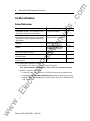
Physical Dimensions
.c
om
MicrologixlM 1000 Programmable Controllers
4
Length: mm (in.)
Depth: mm (in.)
Height mm (in.)
L10BWA
120 (4.72)
73 (2.87)
80 (3.15)
ua
ls
Controller: 1761L16BWA
L16NWA
L16AWA
133 (5.24)
L20AWA-5A
200 (7.87)
L20BWA-5A
an
L32AWA
L32BWA
L32AAA
L10BWB
40 (1.57)
120 (4.72)
tM
L10BXB
L16BBB
L16BWB
L32BBB
L32BWB
ca
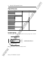
Controller Spacing
lP
200 (7.87)
ar
L16NWB
L20BWB-5A
tri
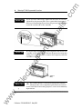
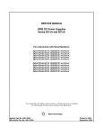
The following figure shows the recommended minimum spacing for the controller.
Top
lec
Side
B
w
.E
A
�
000000000
�
000000
Bottom
A. Greater than or e qual to 50.8 mm (2 in.)
B. Greater than or equa I to 50.8 mm (2 in.)
B
ww
w
Note: The controller is shown horizontally mounted.
Publication 176 1- I N00 1 B-MU-P- May2002
.c
om
Micrologix™ 1000 Programmable Controllers
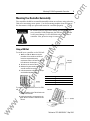
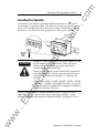
Mounting Your Controller Horizontally
5
The controller should be mounted horizontally within an enclosure using either the
ua
ls
DIN rail or mounting screw option. Use the mounting template from the front of
this document to help you space and mount the controller properly.
Be careful of metal chips when drilling mounting holes for
your controller. Drilled fragments that fall into the controller
could cause damage. Do not drill holes above a mounted
controller if the protective wrap is removed.
tM
an
ATTENTION
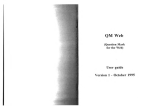
Using a DIN Rail
To install your controller on the DIN rail:
ar
1. Mount your DIN rail. (Make sure that the
placement of the controller on the DIN rail
meets the recommended spacing
requirements. Refer to the mounting template
from the back of this document.)
lP
Mounting
jl Template
2. Hook the top slot over the DIN rail.
ca
3. While pressing the controller against the rail.
snap the controller into position.
lec
tri
4. Leave the protective wrap attached until you
are finished wiring the controller.
Call-out
Dimension
A
84 mm (3.3 in.)
c
16 mm (0. 63 in. )
8
33 mm (1. 3 in. ) maximum
.E
To remove your controller from the DIN
rail:
1. Place a screwdriver in the DIN rail latch at the
bottom of the controller.
ww
w
2. Holding the controller. pry downward on the
latch until the controller is released from the
DIN rail.
Publication1761-IN001 8-MU-P- May2002
w
ww
.E
tri
lec
an
tM
ar
lP
ca
ua
ls
.c
om
.c
om
6
Micrologix™1000 Programmable Controllers
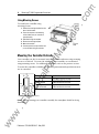
Using Mounting Screws
To install your controller using
mounting screws:
ua
ls
1. Remove the mounting template from the
back of this document.
2. Secure the template to the mounting
surface. (Make sure your controller is
spaced properly.)
3. Drill holes through the template.
4. Remove the mounting template.
Mount the controller.
an
5.
)
tM
6. Leave the protective wrap attached until
you are finished wiring the controller.
Protective
Wrap
Mounting Your Controller Vertically
ar
Your controller can also be mounted vertically within an enclosure using mounting
screws or a DIN rail. To insure the stability of your controller, we recommend
using mounting screws. For additional information, refer to the previous section.
lP
To insure the controller's reliability, the following environmental specifications must
ca
not be exceeded.
Description:
Specification:
Operating Temperature
Operating Shock
(Panel mounted)
9.0g peak acceleration (11 ± 1 ms duration)
3 times each direction, each axis
Operating Shock
(DIN rail mounted)
7.Dg peak acceleration (11 ± 1 ms duration)
3 times each direction, each axis
tri
Side
Side
A
lec
(1)
DC input voltage derated linearly from +30°C (3DV to 26. 4V).
A. Greater than or equal to 50.8 mm (2 in.).
.E
Note: When mounting your controller vertically, the nameplate should be fa cing
ww
w
downward.
Publication1761-IN00 1 8-MU-P- May2002
.c
om
Micrologix™ 1000 Programmable Controllers
Wiring Your Controller
Wire Size: (2 wire maximum per terminal screw)
Solid
#14 to #22 AWG
Stranded
#16 to #22 AWG
IMPORTANT
ua
ls
Wire Type:
7
The diameter of the terminal screw head is 5.5 mm (0.220 in.).
The input and output terminals of the MicroLogix 1000 controller
w
an
are designed for the following spade lugs:
Dimension
Call-out
c
6.35 mm (0.250 in.)
tM
X
E
10.95 mm (0.431 in.) maximum
14.63 mm (0.576 in.)
L
L
w
X
6.35 (0.250 in.)
ar
E
lP
C+X
3.56 mm (0.140 in.)
9.91 mm (0.390 in.) maximum
ww
w
.E
lec
tri
ca
We recommend using either of these AMP (or equal) spade lugs: part number
53120-1, if using 22-16 AWG, or part number 53123-1, if using 16-14 AWG.
Publication176 1-IN001 8-MU-P- May2002
.c
om
Micrologix™1000 Programmable Controllers
8
If you use wires without lugs, make sure the wires are securely
captured by the pressure plate. This is particularly important at
the four end terminal positions where the pressure plate does not
ua
ls
IMPORTANT
Be careful when stripping wires. Wire fragments that fall into the
controller could cause damage. Remove the protective wrap after
wiring your controller. Failure to remove the wrap may cause the
controller to overheat.
.E
lec
tri
ca
lP
IMPORTANT
ar
tM
an
touch the outside wall of the controller.
�
-
This symbol denotes a functional earth ground terminal
which provides a low impedance path between electrical
circuits and earth for non-safety purposes, such as noise immunity
improvement.
ww
w
IMPORTANT
Protective
Wrap
Publication 176 1-1 N001 8-MU-P- May2002
w
ww
.E
tri
lec
an
tM
ar
lP
ca
ua
ls
.c
om
.c
om
Micrologix™ 1000 Programmable Controllers
Grounding Your Controller
9
In solid-state control systems, grounding helps limit the effects of noise due to
electromagnetic interference (EMI). Run the ground connection from the ground
ua
ls
screw of the controller (third screw from left on output terminal rung) to the
ground bus. Use the heaviest wire gauge listed for wiring your controller.
Protective Wrap
ATTENTION
ar
tM
an
J{ (remove after wiring)
A ll devices connected to the user 24V power supply or to the
RS-232 channel must be referenced to chassis ground or
lP
floating. Failure to follow this procedure may result in
property damage or personal injury.
ca
Chassis ground, user 24V ground, and the R.S-232 ground are
internally connected. You must connect the chassis ground
terminal screw to chassis ground prior to connecting any
devices.
lec
tri
On the 1761-LlOBWB, -LlOBXB, -L16BWB, -L16BBB, -L16NWB,
-L20BWB-5A , -L32BBB, and -L32BWB controllers, the ground
associated with the user supplied 24V DC input power and chassis
ground are internally connected.
You must also provide an acceptable grounding path for each device in your
ww
w
.E
application. For more information on proper grounding guidelines, see the
Industria/Automation Wiring and Grounding Guidelines, (publication 1770-4.1).
Publication1761-IN001 8-MU -P - May2002
w
ww
.E
tri
lec
an
tM
ar
lP
ca
ua
ls
.c
om
.c
om
10
MicrologixlM 1000 Programmable Controllers
Surge Suppression
Inductive load devices such as motor starters and solenoids require the use of some
type of surge suppression to protect the controller output contacts. Switching
ua
ls
inductive loads without surge suppression can significantly reduce the life
expectancy of relay contacts. By adding a suppression device directly across the
coil of inductive devices, you prolong the life of the output circuits. You also
reduce the effects of radiated voltage transienl<> and prevent electrical noise from
radiating into system wiring and facility.
The following diagram shows an output with a suppression device. We
VAC/DC
I
Out 0
-c=J-
Out 2
�
'-::.:/
Out 4
Out 5
Out 6
Out 7
ca
COM
lP
Out 3
ar
Out 1
ac or de
Outputs
Suppression
Device
tM
tdc or L 1
an
recommend that you locate the suppression device as close as possible to the load
device.
de COM or L2
If you connect a micro controller FET output to an inductive load, we recommend
ww
w
.E
lec
tri
that you use an 1N4004 diode for surge suppression, as shown in the illustration on
page 11.
Publication 176 1-IN00 1 B-MU-P- May2002
w
ww
.E
tri
lec
an
tM
ar
lP
ca
ua
ls
.c
om
.c
om
Micrologix™1000 Programmable Controllers
11
Suitable surge suppression methods for inductive load devices include a varistor, an
RC network, or, for de loads, a diode. These components must be appropriately
rated to suppress the switching transient characteristic of the particular inductive
device. See the table on page 12 for recommended suppressors.
ua
ls
A s the following diagram illustrates, these surge suppression circuits connect
directly across the load device. This reduces arcing and damage of the output
contacts. (High transients can cause arcing that occurs when switching off an
inductive device.)
O utput Devic e
tM
O utput Device
an
S urge S uppression for Induct ive ac Load Devices
RC Network
ar
Varistor
O utput Devic e
Diode (A surge suppressor
can also be used.)
If you connect a micro controller triac output to control an inductive load, we
lP
recommend that you use varistors to suppress noise. Choose a varistor that is
appropriate for the appli cation. The suppressors we recommend for triac outputs
when switching 120V ac inductive loads are a Harris MOV, part number V 175
ca
LA10 A , or an A llen-Bradley MOV, catalog number 599-K04 or 599-KA04. Consult
the varistor manufacturer's data sheet when selecting a varistor for your appli cation.
tri
For inductive de load devices, a diode is suitable. A 1N4004 diode is acceptable for
most applications. A surge suppressor can also be used. See the table on page 12
ww
w
.E
lec
for recommended suppressors.
Publication 176 1-IN00 1B-MU-P- May2002
w
ww
.E
tri
lec
an
tM
ar
lP
ca
ua
ls
.c
om
.c
om
12
Micrologix™ 1000 Programmable Controllers
Recommended Surge Suppressors
We recommend the Allen-Bradley surge suppressors shown in the following table
Device
Coil Voltage
Bulletin 509 Motor Starter
Bulletin 509 Motor Starter
120V ac
240V ac
Bulletin 100 Contactor
Bulletin 100 Contactor
120V ac
240V ac
Bulletin 709 Motor Starter
120V ac
12V de
12V de
Bulletin 700 Type R Relay
Bulletin 700 Type RM Relay
Bulletin 700 Type N, P, or PK Relay
ca
Miscellaneous electromagnetic devices limited to
35 sealed VA
Vanstor- Not recommended for use on relay outputs.
(2)
RC Type- Do not use with triac outputs.
ww
w
.E
lec
tri
(1)
Publication 176 1-I N00 1 8-MU-P- May2002
None Required
199-FSMA9
199-FSMA9
48V de
48V de
199-FSMA9
115-125V de
115-125V de
199-FSMA10
230-250V de
230-250V de
199-FSMA11
150V max, ac or DC
700-N24 ( 2l
150V max, ac or DC
700-N24 (Zl
lP
Bulletin 700 Type R Relay
Bulletin 700 Type RM Relay
1401-N10
24V de
24V de
ar
Bulletin 700 Type R Relay
Bulletin 700 Type RM Relay
Bulletin 700 Type R Relay
Bulletin 700 Type RM Relay
199-FSMA1(Zl
199-FSMAz(Zl
an
ac coil
Bulletin 700 Type R Relay
Bulletin 700 Type RM Relay
Suppressor Catalog
Number
599-K04 (1l
599-KA04 (1l
tM
Bulletin 700 Type R, RM Relays
ua
ls
for use with Allen-Bradley relays, contactors, and starters.
w
ww
.E
tri
lec
an
tM
ar
lP
ca
ua
ls
.c
om
.c
om
Micrologix™ 1000 Programmable Controllers
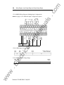
Sinking and Sourcing
13
ua
ls
A ny MicroLogix 1000 DC input can be configured as sinking or sourcing depending
on how the DC COM terminal is wired.
Definition:
Sinking
The input energizes when high-level voltage is applied to the input terminal (active
high). Connect the power supply VDC (-) to the corresponding DC COM terminal.
Sourcing
The input energizes when low-level voltage is applied to the input terminal (active low).
Connect the power supply VDC (+) to the corresponding DC COM terminal.
Sinking and Sourcing Wiring Examples
tM
1761-L32BWA
an
Mode:
Sinking Inputs
Sourcing Inputs
ca
lP
ar
Sourcing Inputs
Sinking Inputs
ww
w
.E
lec
tri
------- 14-30VOC --------;r.-
Publication 176 1-IN00 1B-MU-P- May2002
w
ww
.E
tri
lec
an
tM
ar
lP
ca
ua
ls
.c
om
MicrologixlM 1000 Programmable Controllers
Wiring Your Analog Channels
.c
om
14
A nalog input circuits can monitor current and voltage signals and convert them to
or a
serial digital data. The analog output can support either a voltage
current
an
ua
ls
function as shown in the following illustration.
tM
Jumper
unused
inputs.
ar
You can configure either voltage or current
output operation.
meter
ca
tri
2-Wire Transmitter
lP
The controller does not provide loop power for analog inputs. Use a power supply
that matches the transmitter specifications as shown below.
Power
.E
lec
.
•. • •
Transmitter
Sllpply
w
4-Wire Transmitter
ww
•. • •
Supply .... .... • • · • Signal.
GNO
·
3-Wire Transmitter
.
Publication 1761-I N001 8-MU-P- May2002
.
.
·
· ·
Coo�td!!er ·
···-.
-·
. . .
· · · · · ·
· ·
w
ww
.E
tri
lec
an
tM
ar
lP
ca
ua
ls
.c
om
.c
om
Micrologix™ 1000 Programmable Controllers
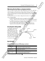
Minimizing Electrical Noise on Analog Controllers
15
Inputs on analog controllers employ digital high-frequency filters that significantly
reduce the effects of electrical noise on input signals. However, because of the
ua
ls
variety of applications and environments where analog controllers are in.<;talled and
operated, it is impossible to ensure that all environmental noise will be removed by
the input filters.
Several specific steps can be taken to help reduce the effects of environmental
noise on analog signals:
•
install the MicroLogix 1000 system in a properly rated (i.e., NEMA)
•
an
enclosure. Make sure that the MicroLogix 1000 system is properly grounded.
use Belden cable #8761 for wiring the analog channels, making sure that the
drain wire and foil shield are properly earth grounded.
route the Belden cable separate from any ac wiring. Additional noise
immunity can be obtained by routing the cables in grounded conduit.
Use shielded communication
cable (Belden #8761). The
Foil Shield
lP
Belden cable has two signal
wires (black and clear), one
ar
Grounding Your Analog Cable
tM
•
Insulation
drain wire, and a foil shield.
ca
The drain wire and foil shield
must be grounded at one end
of the cable. Do not ground
the drain wire and foil shield
at both ends of the cable.
lec
tri
Drain Wire
Specifications
Environmental Specifications (all Micrologix controllers)
Specification
Operating Temperature
oac to +55° C (+32°F to +131 °F) tor horizontal mounting
oac to +40°C (+32°F to +1 04°F) tor vertical mounting11l
.E
Description
Storage Temperature
Operating Humidity
ww
w
Agency Certification (when
product or packaging is
marked)
(1)
5 to 95% non-condensing
•
•
•
C-UL Class I. Division 2 Groups A,B,C,D certified
UL listed (Class I. Division 2 Groups A,B,C,D certified)
CE/C-Tick compliant for all applicable directives
DC input voltage derated li nearly from t30°C (3DV to 26.4V)
Publication1761-IN001B-MU-P- May2002
w
ww
.E
lec
an
tM
ar
ca
lP
tri
ua
ls
.c
om
.c
om
Micrologix™ 1000 Programmable Controllers
16
General Specifications
1761-L
16AWA 32AWA 108WA 168WA 328WA 32AAA 108X8 108W8 328W8
16NWA
16888 168W8 32888
16NW8
Specification:
ua
ls
Description:
Memory Size and
Type
1 K EEPROM (approximately 737 instruction words: 437 data words)
Power Supply
Voltage
85-264V ac, 47-63 Hz
15 VA
19 VA
24 VA
26 VA
240V ac
21 VA
25 VA
32 VA
33 VA
24V de
Not Applicable
Power Supply Max
Inrush Current
29 VA
16 VA
36 VA
22 VA
Not Applicable
an
120V ac
5W
30A for 8 ms
30A for 4 ms
24V de Sensor Power Not Applicable
(V de at rnA)
200 rnA
Max Capacitive Load
(User 24V de)
200 �F
Not Applicable
50,000 minimum
Vibration
Operating: 5 Hz to 2kHz. 0.381 mm (0.015 in.) peak to peak/2.5g panel mounted.(l) 1hr
per axis
Non-operating: 5 Hz to 2kHz. 0.762 mm (0.030 in.) peak to peak/5g, 1hr per axis
Shock(Z)
Operating: 1Og peakacceleration(7 .5g DIN rail mounted) (3l(11±1 ms duration) 3 times
each direction, each axis
Non-operating: 20g peak acceleration (11±1 ms duration). 3 times each direction, each
axis
Terminal Screw
Torque
0.9 N-m maximum (8.0 in.-lbs)
Electrostatic
Discharge
EN 61000-2 at 8K V
lP
ca
tri
Isolation
(1)
(2)
EN 61000-3 at 10 V/m. 27 MHz - 1000 MHz; 3V/m. 87 MHz - 108 MHz. 174 MHz- 230
MHz. and 470 MHz - 790 MHz
EN 61000-4 at 2K V Power Supply, 1/0: 1K V Comms
lec
Fast Transient
ar
Power Cycles
Radiated
Susee ptibi Iity
1500V ac
DIN rail mounted c ontroller IS 1 g.
Refer to page 6 for verticalmounting spec ifications.
.E
(3) Relays are derated an additional2.5g on 32 pt. c ontrollers.
Analog General Specifications
Description:
Specification:
20AWA-5A
1761-L
j208WA-5A
j208W8-5A
Memory Size and Type
1 K EEPROM (approximately 737 instruction words: 437 data words)
Power Supply Voltage
85-264V ac, 47-63 Hz
w
ww
7W
tM
Power
Supply
Usage
20.4-26.4V de
Publication 1761- I N001 8-MU-P- May2002
I 20.4-26.4V de
w
ww
.E
tri
lec
an
tM
ar
lP
ca
ua
ls
.c
om
.c
om
Micrologix™ 1000 Programmable Controllers
Description:
Specification: 1761-L
20AWA-5A
20BWB-5A
120V ac 20 VA
30 VA
Not Applicable
240V ac 27 VA
38 VA
24V de
ua
ls
Power
Supply
Usage
20BWA-5A
17
Not Applicable
10W
24V de Sensor Power (V Not Applicable
de at rnA)
200 rnA
Max Capacitive Load
(User 24V de)
200 �F
Not Applicable
50,000 minimum
Vibration
Operating: 5 Hz to 2kHz. 0.381 mm (0.015 in.) peak to peak/2.5g panel mounted,Ill 1 hr
per axis
Non-operating: 5 Hz to 2kHz, 0.762 mm (0.030 in.) peak to peak/5g, 1hr per axis
Shoc �21
Operating: 1Dg peak acceleration (7.5g DIN rail mounted)l31 (11±1 ms duration) 3 times
each direction, each axis
Non-operating: 2Dg peak acceleration (11±1 ms duration). 3 times each direction.
each axis
tM
an
Power Cycles
Terminal Screw Torque 0.9 N-m maximum (8.0 in.-lbs)
ar
Electrostatic Discharge EN 61000-2 at 8K V Discrete 1/0
4K V Contact. 8K V Air for Analog 1 /0
Radiated Susceptibility EN 61000-3 at 10 V/m. 27 MHz - 1 ODD MHz
3 V/m. 87 MHz - 108 MHz, 174 MHz - 230 MHz, and 470 MHz - 790 MHz
EN 61000-4 at 2K V Power Supply, 1 /0; 1K V Comms
Isolation
15DDV ac
lP
Fast Transient
DIN ratI mounted c ontroller ts 1 g.
(2)
Refer to page 6 for vertical mounting spec ifications.
(3)
Relays are derated an additional 2.5g on 20 pt. c ontrollers.
ca
(1)
Description
tri
General Input Specifications
Specification
100-120V ac Controllers
79 to 132V ae, 47 to 63 Hz
14 to 3DV de
On Voltage
79V ac min.
132V ac max.
14V de min.
24V de nominal
26.4V de max. at t55°C (+131°F)
30.DV de max. at t30°C (+86°F)
Off Voltage
20V ae
5V de
On Current
5.0 rnA min. at 79V ac 47 Hz
12.0 rnA nominal at 12DV ae 60 Hz
16.0 rnA max. at 132V ae 63 Hz
2.5 rnA min. at 14V de
8.0 rnA nominal at 24V de
12.0 rnA max. at 3DV de
Off Current
2.5 rnA max.
1.5 rnA max.
Nominal lmpedanee
12K ohms at 50 Hz
1 OK ohms at 60 Hz
3K ohms
250 rnA max.111
Not Applicable
ww
w
.E
lec
Voltage Range
24V de Controllers
Inrush Maximum
(1) To reduce the inrush maximum to 35 mA, apply a 6.8K ohm, 5W resistor in senes with the input. The on-state voltage
inc reases to 9 2V ac as a result
Publication 176 1-IN00 1 8-MU-P- May2002
w
ww
.E
tri
lec
an
tM
ar
ca
lP
ua
ls
.c
om
Micrologix™ 1000 Programmable Controllers
AC/DC Input Specifications for 1761-L16NWA and 1761-L16NWB
DC Excitation
Minimum
18V ac
14V de
Nominal
24V ac
24V de
Maximum
26.4V ac at 55°C ( 131°F)
30V ac at 30°C (86°F)
26.4V de at 55° C (131 °F)
30V de at 30°C (86°F)
On State Voltage
ua
ls
AC Excitation121
Specification111
3.0 rnA at 18V ac
2.5 rnA at 14V de
8.0 rnA at 24V ac
8.0 rnA at 24V de
Maximum
12 rnA at 30V ac
12 rnA at 30V de
Off State Voltage
Minimum
O.OV ac
O.OV de
Maximum
3.0V ac
Off State Current
Minimum
1.0 mA
Frequency
Nominal
50/60Hz
Range
47 to 63 Hz
Minimum
2 ms
Maximum
20 ms
Minimum
10 ms
Maximum
20 ms
1.5 mA
see Turn On lime /Turn Off lime
tM
Turn Off Time!3l
5.0V de
2 ms
20 ms
ar
Turn On Time!3l
an
Minimum
Nominal
On State Current
.c
om
18
Input circuits may be operated ac or de on a group basis only.
All ac specifications are sinusoidal RMS values.
20 ms
lP
(1)
(2)
10 ms
(3) Turn On and Turn Off Times are not adjustable.
Description
Voltage Input Range
tri
Current Input Range
Type of Data
ca
Analog Input Specifications
lec
Input Coding -21 to +21 rnA - 1 LSB. -10.5 to +10.5V de - 1 LSB
-10.5 to +10.5V de - 1LSB
-21 to +21 rnA- 1 LSB
16-bit signed integer
-32.768 to +32,767
21oKn
Current Input Impedance
1600
Input Resolution!1l
16 bit
Non-linearity
0.002%
Overall Accuracy ooc to +55° C
±.0.7% of full scale
Overall Accuracy Drift ooc to +55° C (max.)
±0.176%
Overall Error at +25°C (+77°F) (max.)
±0.525%
.E
Voltage Input Impedance
Voltage Input Overvoltage Protection
24V de
Current Input Overcurrent Protection
±50 rnA
Input to Output Isolation
30V rated working/500V isolation
w
ww
Specification
Field Wiring to Logic Isolation
(1)
The analog input update rate and input resolut1on are a function of the mput filter select1on.
Publication 176 1-IN00 1 8-MU-P- May2002
w
ww
.E
tri
lec
an
tM
ar
lP
ca
ua
ls
.c
om
.c
om
Micrologix™1000 Programmable Controllers
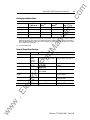
Analog Input Update Rates
Programmable Filter Characteristics
Settling Time
(mSec)l1l
Resolution
(Bits)
ua
ls
Update Time
(mSec)l1l
1st Notch Freq (Hz) Filter Bandwidth
(-3 dB Freq Hz)
19
10
2.62
100.00
400.00
16
50
13.10
20.00
80.00
16
6o(Z)
15.72
16.67
66.67
250
65.50
4.00
16.00
16
15
The total update t1me for each channel Is a combmat1on of the Update T1me and the Settlmg T1me. When more than one
analog input channel is enabled, the maximum update for each channel is equal to one ladder scan time plus the channel's
Update Time plus Settling Time. When only one analog input channel is enabled, the maximum update for the channel is
equal to the Update Time plus one ladder scan time for all except the first update after Going to Run (GTR). The first update
time is increased by the Settling Time.
(2)
60Hz is the default setting.
tM
an
(1)
General Output Specifications
MOSFET
Triac
Relay
Voltage
See Wiring Diagrams, p. 121.
Max Load Current
See Relay
Contact
Ratings on
page 20.
1.0A per point at +55° C (+131o F) 0.5A per point at +55° C (131o F)
1.5A per point at +30° C (+86° F) 1.0A per point at +30° C (86° F)
Min Load Current
10.0 mA
1 mA
10.0 mA
Current per Controller
1440 VA
3A for L16BBB
6A for L32BBB
1440 VA
8.0A
3A for L16BBB
6A for L32BBB
Not Applicable
Max Off State Leakage
Current
OmA
1 mA
2 mA at 132V ac
4.5 mA at 264V ac
Off to On Response
10 ms max.
0.1 ms
8.8 ms at 60 Hz
10.6 ms at 50 Hz
On to Off Response
10 ms max.
1 ms
11.0 ms
lP
ca
lec
tri
Current per Common
ar
Type
Surge Current per Point Not Applicable 4A for 10 msl1l
Repeatability is once every 2 seconds at +55° C (+131oF).
ww
w
.E
(1)
1 OA for 25 ms l1l
Publication1761-IN001 8-MU-P- May2002
w
ww
.E
tri
lec
an
tM
ar
lP
ca
ua
ls
.c
om
Relay Contact Rating Table
Amperes
Amperes
Continuous
Make
Break
240V ac
7.5A
0.75A
120V ac
15A
1.5A
125V de
0.22Ai1l
1.0A
24V de
1.2AI1l
2.0A
Break
180 VA
28 VA
. .
For de voltage appli cations, the make/break ampere ratmg for relay contacts can be determined by d1v1dmg 28 VA by the
applied de voltage. For example, 28 VA.;. 48V de= 0.58A. For de voltage applications less than 48V, the make/break ratings
for relay contacts cannot exceed 2A. For de voltage applications greater than 48V, the make/break ratings for relay contacts
cannot exceed 1 A.
.
tM
Analog Output Specifications
Description
Specification
Voltage Output Range
0 to 1OV de -1 LSB
4 to 20 mA - 1 LSB
Current Output Range
ar
Type of Data
Non-linearity
Load Range - Voltage Output
Load Range - Current Output
lP
Step Response
16-bit signed integer
0.02%
2.5 ms (at 95%)
1K Qto ooQ
o to 500 n
0 to 32.767
can withstand short circuit
ca
Output Coding 4 to 20 mA - 1 LSB, 0 to 1OV de - 1 LSB
Voltage Output Miswiring
Current Output Miswiring
can withstand short circuit
Output Resolution
15 bit
3 msec (maximum)
Overall Accuracy ooc to +55°C
±1.0% of full scale
tri
Analog Output Settling Time
Overall Accuracy Drift ooc to +55°C (max.)
±0.28%
0.2%
30V rated working/50DV isolation
.E
lec
Overall Error at +25°C (+77°F) (max.)
Field Wiring to Logic Isolation
w
ww
Make
1800 VA
an
(1)
2.5A
Voltamperes
ua
ls
Maximum
Volts
.c
om
MicrologixlM1000 Programmable Controllers
20
Publication 1761-I N001 8-MU-P- May2002
w
ww
.E
tri
lec
an
tM
ar
lP
ca
ua
ls
.c
om
.c
om
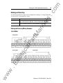
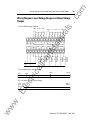
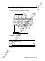
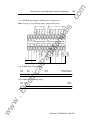
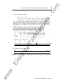
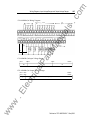
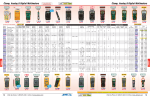
Wiring Diagrams, Input Voltage Ranges and Output Voltage Ranges
121
Wiring Diagrams, Input Voltage Ranges and Output Voltage
Ranges
ua
ls
176 1-L 16 AWA Wiring Diagram
lP
ar
tM
an
-4-- 79-132Vac __.
VAC
ca
VAC
COM
176 1-L 16AWA Input Voltage Range
20V ae
I
79V ae
tri
OV ae
Off
132V ae
On
lec
176 1-L 16 AWA Output Voltage Range
264V ae
125V de
5V ae
5V de
I
Operating Range
I
ww
w
.E
I
OV ae
OV de
Publication 176 1-IN00 1B-MU-P- May2002
w
ww
.E
tri
lec
an
tM
ar
lP
ca
ua
ls
.c
om
.c
om
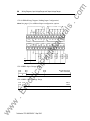
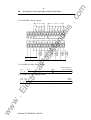
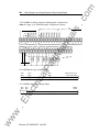
Wiring Diagrams, Input Voltage Ranges and Output Voltage Ranges
122
ar
tM
an
ua
ls
1761-L32AWA Wiring Diagram
ZOV ae
OV ae
Off
13ZV ae
79V ae
ca
1
lP
1761-L32AWA Input Voltage Range
On
1761-L32AWA Output Voltage Range
I
ww
w
.E
lec
I
5V ae
5V de
tri
OV ae
OV de
Publication 176 1-I N00 1 8-MU-P- May2002
Z64V ae
125V de
Operating Range
I
w
ww
.E
tri
lec
an
tM
ar
lP
ca
ua
ls
.c
om
.c
om
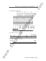
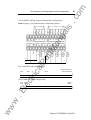
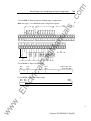
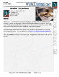
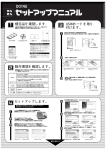
Wiring Diagrams, Input Voltage Ranges and Output Voltage Ranges
1761-LlOBWA Wiring Diagram (Sinking Input Configuration)
14-30VDC
..
..
VDC
VDC
lP
ar
tM
an
VDC
ua
ls
Note: See page 13 for additional input configuration options.
123
VAC
ca
VAC
COM
1761-L10BWA Input Voltage Range
SV de
SV de
OV de
OV de
tri
I
Off
lec
I
1761-LlOBWA Output Voltage Range
OV ae
OV de
I
On
264V ae
125V de
5V ac
5V de
I
Operating Range
I
I
ww
w
.E
I
26.4V de at 55°C (131°F)
30V de at 30°C (86l)
14V de
14V de
Publication 1761-IN001 8-MU-P- May2002
w
ww
.E
tri
lec
an
tM
ar
lP
ca
ua
ls
.c
om
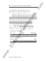
Wiring Diagrams, Input Voltage Ranges and Output Voltage Ranges
1761-L16BWA Wiring Diagram (Sinking Input Configuration)
ar
tM
an
ua
ls
Note: See page 13 for additional input configuration options.
.c
om
124
VAC
lP
VAC
COM
5V de
5V de
OV de
OV de
I
Off
Z6.4V de at 55'C (13rF)
30V de at 30'C (86'F)
14V de
14V de
On
tri
I
ca
1761-L16BWA Input Voltage Range
lec
1761-L16BWA Output Voltage Range
OV ae
OV de
I
ww
w
.E
I
264V ae
125V de
5V ae
5V de
Publication 176 1-1 N001 8-MU-P- May2002
Operating Range
I
w
ww
.E
tri
lec
an
tM
ar
lP
ca
ua
ls
.c
om
.c
om
Wiring Diagrams, Input Voltage Ranges and Output Voltage Ranges
1761-L16NWA A C Wiring Diagram
18-30V ac
ar
tM
an
ua
ls
.,.._ 18-30V ac �
125
VAC
lP
VAC
COM
Off
26.4V ae at 55"C I131"F)
3V ae
18Vae
I
I
tri
I
OVae
ca
1761-L16NWA A C Input Voltage Range
1761-L16NWA A C Output Voltage Range
I
125V de
Operating Range
ww
w
.E
I
I
On
264V ac
5V ae
5V de
lec
OV ac
OV de
30V ae at 30"C IB6l)
Publication 176 1-IN00 1 8-MU-P- May2002
w
ww
.E
tri
lec
an
tM
ar
lP
ca
ua
ls
.c
om
Wiring Diagrams, Input Voltage Ra nges and Output Voltage Ranges
1761-L16NWA DC Wiring Diagram (Sinking Input Configuration)
ar
tM
an
ua
ls
Note: See page 13 for additional input configuration options.
.c
om
126
VAC
lP
VAC
COM
5V de
5V de
OV de
OV de
I
Off
tri
I
ca
1761-L16NWA DC Input Voltage Range
26.4V de at 55°C (131OF)
30V de at 30°C (86°F)
14V de
14V de
I
On
lec
1761-L16NWA DC Output Voltage Range
OV ae
OV de
I
ww
w
.E
I
5V ae
5V de
Publication 176 1-I N00 1 8-MU-P- May2002
264V ae
125V de
Operating Range
I
I
w
ww
.E
tri
lec
an
tM
ar
ca
lP
ua
ls
.c
om
.c
om
Wiring Diagrams, Input Voltage Ranges and Output Voltage Ranges
1761-L32BWA Wiring Diagram (Sinking Input Configuration)
Note: See page 13 for additional input configuration options.
127
lP
ar
tM
an
ua
ls
,.._________ 14-:JOVOC -------
1761-L32BWA Input Voltage Range
I
Off
26.4V de at 55°C (131OF)
30V de at 30°C (B6°F)
14V de
14V de
On
tri
I
5V de
5V de
ca
OV de
OV de
I
1761-L32BWA Output Voltage Range
5V ae
5V de
lec
OV ae
OV de
I
Operating Range
ww
w
.E
I
264V ae
125V de
Publication 176 1-IN00 1 8-MU-P- May2002
w
ww
.E
tri
lec
an
tM
ar
lP
ca
ua
ls
.c
om
1761-L10BWB Wiring Diagram (Sinking Input Configuration)
ar
tM
an
ua
ls
Note: See page 13 for additional input configuration options.
.c
om
Wiring Diagrams. Input Voltage Ranges and Output Voltage Ranges
128
lP
VDC
ca
VDC
COM
1761-LlOBWB Input Voltage Range
5V de
5V de
OV de
OV de
tri
I
Off
lec
I
26.4V de at ss·c (131.F)
30V de at 3o·c (B6.F)
14V de
14V de
I
On
I
1761-L10BWB Output Voltage Range
OV ae
OV de
I
ww
w
.E
I
264Vae
125V de
5V ae
5V de
Publication 1761-I N001 8-MU-P- May2002
Operating Range
I
w
ww
.E
lec
tri
an
tM
ar
lP
ca
ua
ls
.c
om
.c
om
Wiring Diagrams. Input Voltage Ranges and Output Voltage Ranges
176 1-L 16BWB Wiring Diagram (Sinking Input Configuration)
ar
tM
an
ua
ls
Note: See page 13 for additional input configuration options.
129
VDC
lP
VDC
COM
5V de
5V de
OV de
OV de
I
Off
tri
I
ca
1761-L16BWB Input Voltage Range
26.4V de at 55'C (131'F)
30V de at 30'C (B6'F)
14V de
14V de
I
On
I
lec
1761-Ll6BWB Output Voltage Range
OV ae
OV de
I
264V ac
125V de
Operating Range
I
ww
w
.E
I
5V ae
5V de
Publication176 1-IN00 1B-MU-P- May2002
w
ww
.E
tri
lec
an
tM
ar
lP
ca
ua
ls
.c
om
.c
om
Wiring Diagrams, Input Voltage Ranges and Output Voltage Ranges
130
1761-L16NWB A C Wiring Diagram
1B-30Vac _._..
1B-30Vac
ar
tM
an
ua
ls
..._
lP
VDC
COM
ca
1761-L16NWB A C Input Voltage Range
18Vae
3V ae
OVac
Off
26.4Vae at 55°C (131 OF)
30Vae at 30°C (86°F)
On
5Vac
5V de
I
ww
w
.E
lec
I
OVac
OV de
tri
1761-L16NWB A C Output Voltage Rarige
Publication 176 1-IN001 8-MU-P- May2002
264Vae
1Z5V de
Operating Range
I
w
ww
.E
tri
lec
an
tM
ar
lP
ca
ua
ls
.c
om
.c
om
Wiring Diagrams, Input Voltage Ranges and Output Voltage Ranges
1761-L16NWB DC Wiring Diagram (Sinking Input Configuration)
ar
tM
an
ua
ls
Note: See page 13 for additional input configuration options.
131
VDC
lP
VDC
COM
ca
1761-L16NWB DC Input Voltage Range
5V de
OV de
On
tri
Off
26.4V de at 55"C I131"F)
30V de at 30"C IB6"F)
14V de
lec
1761-L16NWB DC Output Voltage Range
OV ae
OV de
I
264V ae
125V de
Operating Range
ww
w
.E
I
5V ae
5V de
Publication 176 1-IN00 1 8-MU-P- May2002
w
ww
.E
tri
lec
an
tM
ar
lP
ca
ua
ls
.c
om
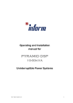
1761-L32BWB Wiring Diagram (Sinking Input Configuration)
Note: See page 13 for additional input configuration options.
ua
ls
-4------ 14-30VOC -------
tM
an
-14-30VOC-
.c
om
Wiring Diagrams, Input Voltage Ranges and Output Voltage Ranges
132
ar
voc
COM
I
I
Off
ca
5V de
5V de
OV de
OV de
lP
1761-L32BWB Input Voltage Range
26.4V de at 55'C {131'F)
30V de at 30'C {86'F)
14V de
14V de
I
On
OV ac
OV de
I
.E
w
ww
Z64V ac
1Z5V de
5V ac
5V de
lec
I
tri
1761-L32BWB Output Voltage Range
Publication 176 1-1 N001 8-MU-P- May2002
Operating Range
I
w
ww
.E
lec
an
rtM
lP
a
ca
tri
ua
ls
.c
om
.c
om
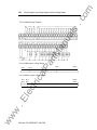
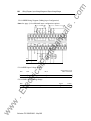
Wiring Diagrams, Input Voltage Ranges and Output Voltage Ranges
ar
tM
an
ua
ls
1761-L32AAA Wiring Diagram
133
OV ac
Off
ca
I
20V ac
lP
1761-L32AAA Input Voltage Range
132V ac
79V ac
On
1761-L32AAA Output Voltage Range
264V ac
85V ac
tri
OV ac
Operating Range
ww
w
.E
lec
Note: See the 1761-L32AWA wiring diagram on page 122 for relay output voltage range.
Publication 1761-IN001B-MU-P- May2002
w
ww
.E
tri
lec
an
tM
ar
lP
ca
ua
ls
.c
om
.c
om
134
Wiring Diagrams, Input Voltage Ranges and Output Voltage Ranges
1761-L10BXB Wiring Diagram (Sinking Input Configuration)
ar
tM
an
ua
ls
Note: See page 13 for additional input configuration options.
VDC
lP
VDC
COM
DV de
ca
1761-L10BXB Input Voltage Range
5V de
tri
Off
26.4V de at 55'C (131'F )
3DV de at 30'C (86'F )
14V de
On
.E
lec
1761-LlOBXB Output Voltage Range
ww
w
DV de
Publication 176 1-IN00 1 8-MU-P- May2002
20.4V de
26.4V de
Operating Range
I
w
ww
.E
tri
lec
an
tM
ar
lP
ca
ua
ls
.c
om
.c
om
Wiring Diagrams, Input Voltage Ranges and Output Voltage Ranges
1761-L16BBB Wiring Diagram (Sinking Input Configuration)
ar
tM
an
ua
ls
Note: See page 13 for additional input configuration options.
135
voc
lP
VDC
COM
SV de
SV de
OV de
OV de
Off
I
tri
1
ca
1761-L16BBB Input Voltage Range
26.4V de at SS'C (131'F)
30V de at 30'C (86'F)
14V de
14V de
I
On
I
.E
lec
1761-L16BBB Output Voltage Range
OV de
I
20.4V de
I
26.4V de
Operating Range
I
ww
w
Note: See the 1761-L32AWA wiring diagram on page 122 for relay output voltage range.
Publication 176 1-IN00 1 8-MU-P- May2002
w
ww
.E
tri
lec
an
tM
ar
lP
ca
ua
ls
.c
om
.c
om
136
Wiring Diagrams, Input Voltage Ranges and Output Voltage Ranges
1761-L32BBB Wiring Diagram (Sinking Input Configuration)
ar
tM
an
ua
ls
Note: See page 13 for additional input configuration options.
OV de
ov de
'
ott__�.
_
ca
1L--
5V de
5V de
lP
1761-L32BBB Input Voltage Range
14V de
14V de
'
264V de at ss·c (13rF)
30V de at 3o·c (86.F)
�
---
on
j
____
.E
lec
OV de
tri
1761-L32BBB Output Voltage Range
20.4V de
I
264V de
Operating Range
I
ww
w
Note: See the 1761-L32AWA wiring diagram on page 122 for relay output voltage range.
Publication1761-IN001 8-MU-P- May2002
w
ww
.E
tri
lec
an
tM
ar
lP
ca
ua
ls
.c
om
.c
om
Wiring Diagrams, Input Voltage Ranges and Output Voltage Ranges
1761-L20AWA-5A Wiring Diagram
----- �:�no gels ---
an
ua
ls
.,..._--- 79-132Vac --l2/N
l1
137
tM
Analog
VAC
__,.
ar
VAC
COM
..,..._ Channel
I
I
Off
132V ae
79V ae
I
ca
20V ae
OV ae
lP
1761-L20AWA-5A Input Voltage Range
On
I
1761-L20AWA-5A Output Voltage Range
5V ae
5V de
I
264V ae
125V de
Operating Range
I
ww
w
.E
lec
tri
OV ae
OV de
Publication1761-IN001 8-MU-P- May2002
w
ww
.E
lec
an
tM
ar
ca
lP
tri
ua
ls
.c
om
.c
om
Wiring Diagrams. Input Voltage Ranges and Output Voltage Ranges
138
1761-L20BWA-5A Wiring Diagram (Sinking Input Configuration)
Note: See page 13 for additional input configuration options.
VOC 1+1
,......._
Anal
og
Channel
__.,
ar
tM
an
VOCit/
Analog
Channels
ua
ls
.---- 14-JOVdc------i.,.
VOCI-J
VAG
lP
VAG
COM
5V de
5V de
OV de
OV de
I
tri
Off
ca
1761-L20BWA-5A Input Voltage Range
14V de
14V de
I
26.4V de at 55'C (131'F)
30V de at 30'C (86'F)
On
1
1761-L20BWA-5A Output Voltage Range
5V ae
5V de
.E
lec
OV ae
OV de
I
ww
w
I
Publication1761-IN001 8-MU-P- May2002
264V ae
125V de
Operating Range
I
w
ww
.E
lec
tri
an
tM
ar
lP
ca
ua
ls
.c
om
.c
om
Wiring Diagrams, Input Voltage Ranges and Output Voltage Ranges
176 1-L20BWB-5A Wiring Diagram (Sinking Input Configuration)
-14-30VdcVDC H
�--- 14-30Vdc -----VDCI-1
VDCI+l
Analog
,....._ Channel _,.
VDC
VDC
COM
lP
ar
tM
an
VDC+
ua
ls
Note: See page 13 for additional input configuration options.
139
1761-L20BWB-5A Input Voltage Range
I
Off
tri
I
5V de
5V de
ca
OV de
OV de
14V de
14V de
26.4V de at 55·c (13rF)
30V de at 3o·c (86.F)
I
On
I
176 1-L20BWB-5A Output Voltage Range
I
Operating Range
I
ww
w
I
2 64V ae
125V de
5V ae
5V de
.E
lec
OV ae
OV de
Publication 1761-IN00 1 8-MU-P- May2002
w
ww
.E
lec
tri
an
tM
ar
lP
ca
ua
ls
.c
om
Analog Voltage and Current Input and Output Ranges
A nalog Voltage Input Range
10.5V de
Operating Ran ge
Underran ge
Analog Current Input Range
Overran ge
21 rnA
Op eratin g Ran ge
50 rnA
Overran ge
tM
Underran ge
an
-21 rnA
-50 rnA
24V de
ua
ls
-10.5V de
-24V de
.c
om
Wiring Diagrams, Input Voltage Ranges and Output Voltage Ranges
140
Note: The analog voltage inputs are protected to withstand the application of ±24V de
without damage to the controller. The analog currentinputs are protected towithstandthe
lP
A nalog Voltage Output Range
OV de
I
ar
application of ±50 rnA without damage.
10 V de
I
ca
Operating Range
tri
A nalog Current Output Range
.E
lec
4 mA
Operating Range
20 mA
I
Note: The analog outputs are protected to withstand the short circuiting of the voltage or
ww
w
current outputs without damage to the controller.
Publication1761-IN00 1 8 -MU-P- May2002
w
ww
.E
tri
lec
an
tM
ar
ca
lP
ua
ls
.c
om
.c
om
ua
ls
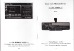
Vlounting Template
tM
an
19Z mm
�--(755 in )
125 mm -----�
(4 9Z in.)
11Z mm
�-----(4.41 i n )
ar
concernant votre automate.
S i e die Sreuerung mit Hilfe dieser Sc
blone. Weitere lnformationen 1ler die Steuerung
befinden sich auf de r ersten Seite des in deutsch
Sprache abgefaGten Abschnitts.
lnstallieren
Usate questa rn a sc he ra per installare i l controllo1
Per ulteriori informazioni sui controllore, fate rife
memo alia prima pagina della sezione n e l la vostr
lingua.
ca
tri
120 mm 1 761 -L1 6BWA, -L1 6BWB. -L16BBB
(4 72 in )
133 mm
1761-L16AWA
1-4----- (5.24 in.
ww
w
.E
lec
1 76H1 0BWA, -L10BWB, -L1 0BXB, -L16NWA, -L1 6NWB
Use this template to install your controller For m
informatio n about your controller, re fer to the firs·
page of your native language section.
Servez-vous de ce gabarit pour 'JIStaller votre aut
mate. fleportez-vous j Ia premiSre page de lu se(
tion en fran1 ais pour de plus amples informatJOn:
lP
80 mm
(3 1 5 i n )
----
Use esta plamilla para instalar s u controlador. Pa
�
�
I
obtener m s in formaci n sabre su controlador ,
consulte Ia primera p gina de Ia secci n en su
idioma nativo.
1761-LZOAWA-5A 1761-LZOBWA-5A 1 76H2081
1 761-L32BWA
1 76H32B
1761-L3ZAWA
1761-L3ZAAA
1761-L3ZBBB
zoo mm
(7.87 in.
w
ww
.E
tri
lec
an
tM
ar
ca
lP
ua
ls
.c
om
.c
om
ua
ls
an
tM
ar
lP
ca
tri
lec
.E
w
ww
Publication176 1 -I N00 1B-MU-P- May2002
w
ww
.E
tri
lec
an
tM
ar
ca
lP
ua
ls
.c
om
.c
om
ua
ls
an
tM
ar
lP
ca
tri
.E
lec
www.rockwellautomation.com
Corporate Headquarters
Rockwell Automation. 777 East Wisconsin Avenue. Suite 1 400. Milwaukee. WI. 53202-5302 USA. Tel: (1 ) 41 4.21 2.5200. Fax: ( 1 ) 414.21 2.5201
Headquarters for Allen-Bralley Products, Roclcwel Software Products and Global Manufacturing Solutions
Americas: Rockwell Automation, 1 201 South Second Street, Milwaukee, W1 53204-2496 USA, Tel: (1 ) 414.382.2000, Fax: (1 ) 41 4.382.4444
Europe: Rockwell Automation SA/NV, Vorstlaan/Boulevard du Souverain 36-BP 3A/B, 1 1 70 Brussels, Belgium. Tel: (32) 2 663 0600, Fax: (32) 2 663 0640
Asia Pacific: Rockwell Automation, 27/F Citicorp Centre, 1 8 Whitfield Road, Causeway Bay, Hong Kong, Tel (852) 2887 4788, Fax: (852) 2508 1 846
Headquarters for Dodge and Reliance Bactric Products
ww
w
Americas: Rockwell Automation. 6040 Ponders Court, Greenville, SC 29615-4617 USA, Tel: (1) 864.297.4800. Fax: ( 1 ) 864.281.2433
Europe: Rockwell Automation. Bruhlstra�e 22. D-74834 Elztai-Dallau. Germany, Tel: (49) 6261 9410, Fax: (49) 6261 17741
Asia Pacific: Rockwell Automation. 55 Newton Road, #1 1 -01/02 Revenue House, Singapore 307987, Tel: (65) 351 6723. Fax: (65) 355 1 733
Publication 176 1-IN00 1 8-MU-P- May2002
Supersedes Publication 1761-5.1.2 · April 1999
PN 40072 0
- 57-01 (2 )
Copyright © 2002 Rockwell Automation. All rights reserved. Printed in the U.S.A.
w
ww
.E
tri
lec
an
tM
ar
lP
ca
ua
ls
.c
om