1
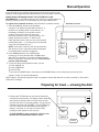
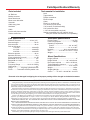
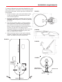
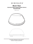
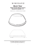
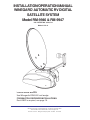
INSTALLATION/OPERATION MANUAL
WINEGARD AUTOMATIC RV DIGITAL
SATELLITE SYSTEM
Model RM-9946 & RM-9947
®
U.S. PATENT NO. 5,532,710
Made in U.S.A.
FOR SLOPED ROOFS:
Use Winegard’s RW-5000 roof wedge.
FOR MULTIPLE RECEIVER INSTALLATIONS:
Dual LNBF is required, see page 16.
Winegard Company • 3000 Kirkwood St. • Burlington, IA 52601-2000
319/754-0600 • FAX 319/754-0787 • www.winegard.com
Printed in U.S.A. © Winegard Company 2001 2451025 11/01/2001
1
IMPORTANT SAFEGUARDS
WARNING: TO REDUCE RISK OF FIRE OR ELECTRICAL SHOCK,
DO NOT EXPOSE TO RAIN OR MOISTURE.
(Not applicable to mount and antenna)
Dangerous voltage
inside enclosure
CAUTION
RISK OF ELECTRIC SHOCK
DO NOT OPEN
Refer to operating, maintenance and safeguard
literature accompanying unit.
CAUTION: TO REDUCE RISK OF ELECTRICAL SHOCK,
DO NOT REMOVE COVER, NO USER-SERVICEABLE PARTS INSIDE.
REFER SERVICING TO QUALIFIED PERSONNEL
1. All the safety and operating instructions should
be read before the appliance is operated.
attention to cord at plug, convenience receptacle
and the point where cord exits from the appliance.
2. The safety and operating instructions should be
retained for future reference.
12. If an outside antenna or cable system is connected to this video product, be sure system is
grounded so as to provide some protection against
voltage surges and built-up static charges. Proper
method is shown below.
10B. If the appliance is equipped with a 3-wire
grounding-type plug, a plug having a third (grounding) pin, this plug will only fit into a grounding-type
power outlet. This is a safety feature. If you are
unable to insert the plug into the outlet, contact an
electrician to replace your obsolete outlet. Do not
defeat the purpose of the grounding-type plug.
11. Power-supply cord should be routed so that it
is not likely to be walked on or pinched by items
placed upon or against it, paying particular
³
10A. If the appliance is equipped with a polarized
alternating-current line plug (a plug having one
blade wider than the other) this plug will fit into the
power outlet only one way. This is a safety feature.
If you are unable to insert the plug fully into the
outlet, try reversing the plug. If the plug should still
fail to fit, contact an electrician to replace your
obsolete outlet. Do not defeat the safety purpose
of the polarized plug.
³
³
9. This video product should be operated only from
the type of power source indicated in electrical
rating printed on the appliance or power supply.
³
³
8. If slots, holes and openings are located in the
housing, they are provided for ventilation and to
ensure reliable operation of the video product and
to protect it from overheating. These openings
should never be covered. The openings should
never be blocked by placing the video product on
a bed, sofa, rug, or other similar surface. This
video product should never be placed near or over
a radiator or heat register. This video product
should not be placed in a built-in installation such
as a bookcase or rack unless proper ventilation is
provided or the manufacturer's instructions have
been adhered to.
Electrical
Service
Equipment
³
7. Do not use this video product near water - for
example, near a bath tub, wash bowl, kitchen sink,
or laundry tub, in a wet basement, or near a
swimming pool, and the like.
Ground Clamp
Antenna Discharge Unit
(NEC Section 810-21)
Grounding Conductors
(NEC Section 810-21)
³
6. Do not use attachments not recommended by
the video product manufacturer as they may cause
hazards.
Antenna
Lead-in Wire
³
5. Unplug this video or audio product from the wall
outlet before cleaning. Do not use liquid cleaners
or aerosol cleaners. Use a damp cloth for cleaning.
EXAMPLE OF ANTENNA GROUNDING AS PER
NATIONAL ELECTRICAL CODE INSTRUCTIONS
³
4. All operating and use instructions should be
followed.
³
3. All warnings on the appliance and in the
operating instructions should be adhered to.
Ground Clamps
Power Service Grounding
Electrode System
(NEC Art. 250, Part N)
NEC - NATIONAL ELECTRICAL CODE
13. An outside antenna system should not be
located in the vicinity of overhead power lines or
other electric light or power circuits, or where it can
fall into such power lines or circuits. When installing an outside antenna system, extreme care
should be taken to keep from touching such power
lines or circuits as contact with them might be fatal.
14. For added protection for this video product
during a lightning storm, or when it is left unattended and unused for long periods of time, unplug
it from the wall outlet and disconnect the antenna
or cable system.
15. Do not overload wall outlets and extension
cords as this can result in a risk of fire or electric
shock.
16. Never push objects of any kind into this video
product through openings as they may touch dangerous voltage points or short-out parts that could
result in a fire or electric shock. Never spill liquid of
any kind on the video product.
2
17. Do not attempt to service this video product
yourself as opening or removing covers may
expose you to dangerous voltage or other hazards. Refer all servicing to qualified service personnel.
18. Unplug this video product from the wall outlet
and refer servicing to qualified service personnel
under the following conditions:
a. When the power supply cord or plug is damaged.
b. If liquid has been spilled or objects have fallen
into the video product.
c. If the video product, except for antenna mounted
preamplifiers and downconverters, has been exposed to rain or water.
d. If the video product does not operate normally
by following the operating instructions. Adjust only
those controls, when provided, that are covered by
the operating instructions. An improper adjustment of other controls may result in damage that
will often require extensive work by a qualified
technician to restore the video product to its normal operation.
e. If the video product has been dropped or the
housing has been damaged.
f. When the video product exhibits a distinct change
in performance - this indicates a need for service.
19. When replacement parts are required, be sure
the service technician has used replacement parts
specified by the manufacturer or have the same
characteristics as the original part. Improper substitutions may result in fire, electric shock or other
hazards.
20. Upon completion of any service or repairs to
this video product, ask the service technician to
perform safety checks to determine that the video
product is in proper operating condition.
21. Note to CATV system installer: This reminder
is provided to call the CATV system installer's
attention to Art. 820-40 of the NEC that provides
guidelines for proper grounding and, in particular,
specifies that the cable ground shall be connected
to the grounding system of the building, as close to
the point of cable entry as possible.
22. This product should be mounted to a wall or
ceiling only as recommended by the manufacturer.
23. The product should be situated away from heat
sources such as radiators, heat registers, stoves
or other products (including amplifiers) that produce heat.
Table of Contents
OPERATION
Introduction ...................................................................................................................................................... 4
Wallplate Control Panel ................................................................................................................................... 5
Automatic Operation ........................................................................................................................................ 6
Manual Operation ............................................................................................................................................ 8
Stowing Dish .................................................................................................................................................... 8
INSTALLATION
Tools Needed ............................................................................................................................................... 3, 9
System Components, Specifications, Warranty Information ........................................................................... 9
Installation Requirements .............................................................................................................................. 10
Mounting Assembly on Roof ..................................................................................................................... 11-12
Mounting Interior Wall plate Controller .......................................................................................................... 14
Wiring... .......................................................................................................................................................... 15
PARTS
Antenna Parts ................................................................................................................................................ 16
Base Assembly .............................................................................................................................................. 17
Turret Assembly/Cover .................................................................................................................................. 18
ADDITIONAL INFORMATION
Troubleshooting ........................................................................................................................................ 19-20
Parts included:
Tools needed for installation:
18 “Reflector
Backup structure
Mount base/turret
Mount cover & bracket
Vent tube
Cable entry plate
Hardware
Cable
Interior wall plate controller
Surface mount box
Level
Tape measure
Phillips screwdriver
Electrical tape
Cutter
Electric or cordless drill
1/8” drill bit (for pilot holes)
7/16” wrench (for dish assembly)
5/16” socket/nut driver
1-1/2” hole saw (cable entry hole)
Sealant compatible with roof material (check
with your vehicle manufacturer for compatibility)
FCC PART 15 STATEMENTS
NOTE: This equipment has been tested and found to comply with the limits for a Class B digital device, pursuant to Part 15
of the FCC Rules. These limits are designed to provide reasonable protection against harmful interference in a residential
installation. This equipment generates, uses and can radiate radio frequency energy and, if not installed and used in accordance with the instructions, may cause harmful interference to radio communication. However, there is no guarantee that
interference will not occur in a particular installation. If this equipment does cause harmful interference to radio or television
reception, which can be determined by turning the equipment off and on, the user is encouraged to try to correct the interference by one or more of the following measures:
• Reorient or relocate the receiving antenna.
• Increase the separation between the equipment and receiver.
• Connect the equipment into an outlet on a circuit different from that to which the receiver is connected.
• Consult the dealer or an experienced radio/TV technician for help.
CAUTION: Any changes or modifications to this equipment not expressly approved by Winegard Company may void
the user’s authority to operate this equipment.
3
Introduction/How Does Digital Satellite TV Work?
Introduction
For Programming information call:
DISH NETWORKTM - 1-800-333-DISH (1-800-333-3474)
DIRECTV® - 1-800-DIRECTV (1-800-347-3288)
ExpressVu - 1-888-SKYDISH (1-888-759-3474)
Congratulations! You have an RV automated digital
satellite reception product — RM-9946. This system,
used with your digital satellite receiver, will deliver
the best reception possible. Your new Winegard digital satellite system was designed for ease of
installation, setup and operation.
Your new Winegard RV Digital Satellite System is an
easy-to-install, easy-to-use satellite TV reception system. Because it mounts on the top of your recreational
vehicle, it goes where you go and provides quality reception of digital satellite signal in the continental
United States only. Check with your programming provider for exact coverage area.
How Does Digital Satellite System
TV Work?
Satellite programming originates from an “uplink” facility on Earth — the facility receives many signals
from different sources, combines the signals digitally
and transmits to the satellites. The satellites (22,300
miles above Earth) receive the uplink signal, amplify
it and then transmit it back to earth in the Ku frequency band. This signal is received by your satellite
antenna whose shape reflects and concentrates the
signal to the LNBF* attached to
the antenna. The LNBF is located at the “focal point” of
signal reflection, that is, the point
at which the maximum amount of
signal is effectively concentrated.
The LNBF amplifies and converts the
signal to the 950 to 1450 MHz range.
The signal is then passed through a
coaxial cable to the electronics box,
then to the receiver where individual
channel selection and processing take
place.
DIGITAL BROADCAST
SYSTEM SATELLITE(S)
HIGH POWER KU-BAND
DOWNLINK SIGNAL
WINEGARD AUTOMATIC
DIGITAL SATELLITE
SYSTEM ANTENNA
WINEGARD
SENSAR® ANTENNA
* Low Noise Block Converter Feed
UPLINK SIGNAL
TELEVISION
SET
RECEIVER
PROGRAMMING UPLINK
CONTROL CENTERS
4
Wall plate control panel description
12. RED LED: Shows Antenna elevated from
stow position (any degree from stow).
1. DISPLAY: LCD (Liquid Crystal Display) shows
instructions and warnings to operator.
11. GREEN LED: Shows Power is on.
ANTENNA
POWER
2. POWER: Turns system on or
off when pressed. To turn On,
hold down one second; to
turn Off, hold down 2
seconds.
3. STOW: Places dish in a
ready-to-travel, or stowed,
position.
Power
Stow
Enter
Manual
4. MANUAL: The operator is
able to manually move the
dish up/down/left/right.
Cancel
6. ARROW LEFT: Use to
manually move dish in a
counter-clockwise direction. Can also be used
to select options in
some sub-menus.
10. ARROW UP: Use to
manually elevate
dish. Can also select
options in some
sub-menus.
9. ARROW RIGHT: Use
to manually control
dish in clockwise
direction. Can
also be used to
select options in
some sub-menus.
8. ARROW DOWN: Use
to manually lower
dish. Can also be
used to select
options in some
sub-menus.
5.CANCEL: Stops any operation in progress.
7. ENTER: Selects the
desired function, for
example: “Press ENTER
to start search”.
5
Automatic System Operation
After parking and leveling vehicle, look for trees, buildings, hills or mountains that might block the satellite signal.
ABOUT YOUR RECEIVER:
If you have a DISH NetworkTM receiver, be sure your system (RM-9946) is set to receive DISH Network satellites. If you
have a DIRECTV® receiver, be sure your system (RM-9946) is set to receive DIRECTV satellites. (The majority of programming for DISH Network is on satellite 119°W; for DIRECTV it is on 101°W.
Contact DIRECTV at 1-800-DIRECTV (1-800-347-3288), DISH Network at 1-800-333-DISH (1-800-333-3474), Canadian customers contact ExpressVu at 1-888-SKYDISH (1-888-759-3474) for more information.
FIRST TIME USE:
System is factory preset to find 119°W (DISH Network). For other providers’ satellites, see page 7, Note 2. The
first time your system is used, it could take up to 10 minutes for GPS acquisition. (This is also true if you have stored
your system for six months or longer, or for vehicles without ignition systems [towables]). This is typical of first time
use; do not think there is a malfunction.
1. Turn TV on and tune to channel 3 or 4 (the output
of your receiver).
Wall Plate Controller
2. Turn on your satellite receiver. The receiver MUST BE
TURNED ON and LNBF COAX PROPERLY ATTACHED (refer to your receiver owner manual).
3. Press the POWER button on the wall plate controller
for one second. (Pressing CANCEL will stop the
search at any time during any process.)
ANTENNA
POWER
4. The Winegard logo, then Software Rev. 1.XX appear
briefly on the display.
Power
5. “Acquiring GPS” appears and remains until the
system acquires the GPS (Global Positioning
System) signal.
Stow
Enter
Manual
6. “Computing look angles” appears. The system is
comparing GPS data and the satellite selected.
Dish/Direct 119° W will be displayed; identify the
satellite related to your receiver.
Cancel
7. For first time operation from your location (see
Note 2, p. 7):
• “Searching for satellite” is displayed. The system is
searching for the satellite and is setting the elevation
for the chosen satellite based on GPS information.
During this process, the message will be replaced by
“Determining satellite location.”
• The system will begin finding the available satellites
while the message “Determining satellite location.” is
displayed. During this process, you may see a picture
or signal from the desired satellite, but the system will
move on to other satellites, “remembering” their
location. Your signal disappears during this process.
• After your system has locked on the satellite of your
choice, the display will read “Enjoy the show.”
8. If you want to change to a different satellite,
wait for message displayed as “Pick a sat < >”. Use
LEFT or RIGHT buttons to scroll through the list of
available satellites for your receiver. After you find the
desired satellite, press ENTER.
• “Moving to (select satellite)” will be
displayed while the system moves to that
satellite. “Current Sat” with the selected
satellite will appear on the display when
locked on that satellite.
9. If you have NOT MOVED from your location, and want to watch the same satellite and dish is stowed:
• Press POWER. “Press ENTER to select
last satellite” will be displayed after GPS is
acquired. Press ENTER to move the
system back to the last satellite viewed.
You do not have to perform the
search function.
(See NOTES and other information on page 7.)
6
Automatic System Operation
DON’T UNDERSTAND A MENU?
If you see a menu in the display you do not understand, press POWER for two seconds to exit that
menu.
NOTE 1:
The system can move directly to any of the available
satellites, if you have a clear view, after the initial
search routine at a location. The display will show the
message “Pick a sat < > ”. It remains for several minutes after search is complete. To get back to menu,
after power has shut off, press POWER. If you have
pressed the Manual button, this will not return you to
menu (“Pick a sat”). A new search must be completed
to regain this feature.
NOTE 2:
First time users can also change search satellite selection at beginning — only while Winegard logo is on
screen. Press RIGHT arrow button one (1) time and
“Satellite selection mode” will be displayed. This is followed by the current selection. To change satellites,
press UP or DOWN arrow buttons until desired satellite
is displayed, then press ENTER.
7
Manual Operation
At any time during any operation, the system may be put in manual control
operation mode by pressing the MANUAL button on the wall plate controller.
WHEN USING THE MANUAL MODE, THE SYSTEM WILL LOSE
INFORMATION. You will not be able to move directly to a satellite without repeating a search process, or automatically go to the last satellite used.
Wall Plate Controller
To regain these automatic features, follow directions in number 3 below.
1. Press the MANUAL button on the wall plate
controller. The display will read “Manual Control.” If
the dish is in stowed position or less than 24° on
the display, the dish is in a less than vertical
position. Press and hold the UP arrow key
to elevate the dish to a 90° (vertical) position. The
display should then read 24° or above in the
lower right hand corner. Now you can move the dish
left and right safely — no moving part of the dish will
come into contact with the roof.
NOTE: A “fail-safe” is built into the unit to prevent the
dish turning until 0 or a greater number is displayed
for elevation when receiver is plugged in.
2. Press ARROW buttons for the desired dish
movement. UP arrow elevates dish, DOWN lowers
dish, LEFT moves dish in a counter-clockwise direction,
RIGHT moves dish in clockwise direction. You cannot go
past the LIMIT message.
3. To exit from the manual operation mode, you can
1) Press CANCEL or
2) Press POWER* or
3) Press STOW
ANTENNA
POWER
Power
Stow
Enter
Manual
Cancel
*If you use the POWER button, remember to hold POWER button in for at least two (2) seconds, then
release. “Power off” should be displayed.
NOTE: When in the Manual Operation mode, any positive number will allow unit to rotate. Less than 0° will result in
“Raise dish” message.
Preparing for travel — stowing the dish
1. Pressing the STOW button at any time will initiate the
command to stow the dish. The display shows “Antenna
Auto Stowing” while the dish is in the process of stowing. After the dish is in the stow position, you will see the
message “Antenna Auto STOWED.” The red LED will go
out. The unit will shut off automatically after approximately 1.5 minutes, or you may turn power off by
holding in Power button for two seconds.
IT IS ADVISABLE to step outside the vehicle to see
that the dish is stowed and ready for travel.
ANTENNA
POWER
Power
Stow
Enter
Manual
Cancel
8
Parts/Specifications/Warranty
Tools needed for installation
Parts included
Level
Tape measure
Phillips screwdriver
Electrical tape
Cutter
Electric or cordless drill
1/8” drill bit (for pilot holes)
7/16” wrench (for dish assembly)
5/16” socket/nut driver
1-1/2” hole saw (cable entry hole)
Sealant compatible with roof material (check
with your vehicle manufacturer for compatibility)
18 “Reflector
Backup structure
Mount base/turret
Mount cover & bracket
Vent tube
Cable entry plate
Hardware
Cable
Interior wall plate controller
Surface mount box
Dish Specifications
Electronics Specifications
Reflector Diameter .................... 46 cm (18")
Antenna height ..................................... 53 cm
Antenna width ...................................... 49 cm
Gain at mid-range
11.2 GHz .............................. 33.22 dBi
12.1 GHz .............................. 33.89 dBi
12.6 GHz .............................. 34.23 dBi
Effective aperture ................................. 46 cm
Aperture efficiency .................................. 73%
Cross polarization (on axis)... .............. -21 dB
Beamwidth at -3 dB .................................. 3.5o
Beamwidth at -10 dB ................................ 7.00
F/D Ratio ................................................. 0.59
Frequency Range ................ 10.95-12.75GHz
Offset angle ............................................... 240
Gauge .................. 22 gauge galvanized steel
Finish: ......... Textured thermoset powder coat
Primary Power ................................. +12 VDC
Power Consumption ........................... 3 amps
Operating Temperature
Interior ................................... 32° to 120°F
Exterior ............................... -10° to +130°F
Humidity ........................ 90% noncondensing
Size ................... 4-1/2"W x 4-1/4"H x 1-3/4"D
Weight ..................................................... 1 lb.
Mount Specifications
Height Lowered .......................................... 8"
Height Raised ..................... 30" vertical max.
Roof space required .......... 40"L x 20"W min.
Turning diameter clearance ..................... 33”
Antenna Movement ................... 2 DC motors
Weight ................................................. 16 lbs.
Shipping Weight .................................. 20 lbs.
Carton ......... 27-3/4"L x 20-3/8"W x 10-3/4"D
Returned units damaged in shipping due to improper packing will be charged to the dealer/customer.
TWO YEAR LIMITED WARRANTY
Winegard Company warrants this Winegard product (excluding receiver) against any defects in materials or workmanship within
two (2) years from date of purchase. No warranty claim will be honored unless at the time the claim is made, you present proof of
purchase to an authorized Winegard dealer (if unknown, please contact Winegard Company, 3000 Kirkwood Street, Burlington, Iowa
52601-2000, telephone 319-754-0600).
Winegard Company (at its option) will either repair or replace the defective product at no charge to you. This warranty covers parts,
but does not cover any costs incurred in removal, shipping or reinstallation of the product. This limited warranty does not apply if the
product is damaged, deteriorates, malfunctions or fails from: misuse, improper installation, abuse, neglect, accident, tampering,
modification of the product as originally manufactured by Winegard, usage not in accordance with product instructions or acts of nature
such as damage caused by wind, lightning, ice or corrosive environments such as salt spray and acid rain.
The Two Year Warranty is provided on the condition that the equipment is properly delivered with all handling and freight charges
prepaid to your Winegard dealer for repair or return to our factory at the above address. Winegard dealers will arrange for the
replacement or repair and return to you, without charge, the product which failed due to defective material or workmanship.
WINEGARD COMPANY WILL NOT ASSUME ANY LIABILITIES FOR ANY OTHER WARRANTIES, EXPRESS OR IMPLIED,
MADE BY ANY OTHER PERSON.
ALL OTHER WARRANTIES WHETHER EXPRESS, IMPLIED OR STATUTORY INCLUDING WARRANTIES OF FITNESS FOR
A PARTICULAR PURPOSE AND MERCHANTABILITY ARE LIMITED TO THE TWO YEAR PERIOD OF THIS WRITTEN WARRANTY.
The foregoing shall be the sole and exclusive remedy of any person whether in contract, tort or otherwise, and Winegard shall not
be liable for incidental or consequential damage or commercial loss, or from any other loss or damage except as set forth above.
Some states do not allow limitations on how long an implied warranty lasts, or the exclusion of limitation of incidental or consequential
damages, so the above limitations or exclusions may not apply to you.
This warranty gives you specific legal rights and you may also have other rights which vary from state to state.
9
Installation requirements
To install the Winegard Automatic Digital Satellite Dish, check
with your RV dealer or manufacturer. Your RV may already be
pre-wired for this system, and/or may have a reinforced roof
area available.
FIGURE 1
1. Choose a location on the roof that will allow the dish
to raise and rotate without interference from other
roof-mounted equipment.
2. Roof space required for operation is 40”L x 20”W
minimum. Refer to Figures 1, 2, 3 and 5 for operating
parameters.
3. The unit must be level, within 3°, for best operation.
Use the hydraulic or manual leveling equipment on
your vehicle to level the roof as much as possible.
Before beginning installation: If the mounting area is
not level, you can use a roof wedge, Figure 4.
Winegard’s RW-5000 roof wedge that will correct tilt up
to 3.7°. For units with severely sloping roofs, more
than one wedge may be needed.
FIGURE 2
4. When choosing a location for the interior wall plate
controller, consider wiring, ease of viewing the information and distance from your television set.
FIGURE 5
CENTER ROOF LINE
FIGURE 3
FIGURE 4
33” DIAMETER
TURNING
CLEARANCE
28”
RW-5000 ROOF
WEDGE & GASKET
FRONT OF VEHICLE
10
VEHICLE ROOF
Mounting motorized dish assembly on roof
1. Position the roof template on the vehicle roof and drill 1/8” holes for the screws. DO NOT drill clear
through into interior of vehicle. The screws fasten mount to the roof only. Be sure the roof can
securely hold system.
2. Place base plate gasket under the base before screwing unit down. Secure the base plate of the
motorized assembly to the roof using appropriate screws. DO NOT APPLY SEALANT AT THIS TIME.
Note: IF YOU ARE USING THE ROOF WEDGE (RW-5000), use the 3/16” gasket included with motorized mount under the roof wedge. Install 1/16” gasket included with the RW-5000 roof wedge between
mount and roof wedge. Longer screws are needed for installation when using roof wedge.
CAUTION!! Cable MUST BE ROUTED AS SHOWN IN FIGURE 6 and 6A to prevent cable wrap! If not
routed correctly, you may STRIP GEARS! BEFORE INSTALLATION, unroll cable to remove kinks.
3. Route cable assembly around the base of the unit, Figure 6. FROM THE BACK OF THE ELECTRONICS
BOX TO THE FIRST CLAMP MUST BE 53”!
4. Drill hole for cable entry in appropriate place. THIS MUST BE 4” MINIMUM FROM FIRST CLAMP! You
can also run cable to an existing cable entry hole that meets the same distance requirements (4” minimum), Figure 6A. Be sure cable is not too tight from mount to entry point when dish is in stow position. If
there is not enough slack in the cable, it will bind and prevent proper operation, or damage the mount.
11
FIGURE 6
First cable
clamp here!
4” MINIMUM from
first clamp to
cable-entry plate
The length of this cable MUST BE 53 inches
from back of electronics housing to clamp. NO
CLAMPS ALONG THIS 53” LENGTH!
FRONT OF
VEHICLE
4”
Cable-entry
plate
20”
16”
CENTER LINE
OF COACH
ROOF
16” from front
center edge of
mount base
FIGURE 6A
Cable-entry plate
FRONT OF
VEHICLE
PASSENGER
SIDE
DRIVER
SIDE
Cable-entry plate
First cable
clamp here!
Cable clamps every 12” from first
cable clamp
PASSENGER
SIDE
20”
16”
CENTER LINE OF
COACH ROOF
Cable-entry plate
FIGURE 6B
16” from front
center edge of
mount base
DRIVER
SIDE
Cable clamps every 12” from first cable
clamp
The length of this cable MUST BE 53 inches
from back of electronics housing to clamp. NO
CLAMPS ALONG THIS 53” LENGTH!
First cable
clamp here!
CENTER LINE OF
COACH ROOF
FRONT OF
VEHICLE
The length of this cable MUST BE 53 inches
from back of electronics housing to clamp. NO
CLAMPS ALONG THIS 53” LENGTH!
PASSENGER
SIDE
20”
16”
16” from front
center edge of
mount base
DRIVER
SIDE
12
5. Cut the cable wrap approximately four (4) inches away from point where it enters the cable-entry plate,
Figure 7, 7A. This allows proper sealant coverage. Do not damage cables when cutting away the cable wrap.
(The cable wrap protects and keeps together in one unit the coaxial cable, electrical cable and 8 wire data
cable.) After cutting, wrap the outer cable wrap with electrical tape as shown, Figure 7, 7A. Push cable
through cable entry point on roof. Do not damage cable. DO NOT APPLY SEALANT AT THIS TIME.
6. Pre-drill 1/8” holes for cable entry plate. Fasten down with screws provided. DO NOT APPLY SEALANT.
FIGURE 7, RM-9946
Cable wrap. Cut 4” away
before putting under cableentry plate.
FIGURE 7A, RM-9947
Cable wrap. Cut 4” away
before putting under
cable-entry plate.
8 wire data cable
8 wire data cable
Coax cable
Electrical cable
Coax cable
Electrical tape,
wrapped at cut
line.
Electrical cable
7. Install the vent tube on the back of the mount base (This is
the side opposite the word FRONT). The hole for the vent
tube is shown in Figure 8. CAUTION: DO NOT seal hole in
vent tube. Put sealant around the outside of the vent tube,
approximately 1/2 inch from end. Push the vent tube into
the hole, Figure 8. The sealant will seal the hole as you
push in. Leave approximately 2 to 2-1/2 inches of the vent
tube extending from the hole. DO NOT APPLY SEALANT
TO ANY SURFACES UNTIL YOU TEST YOUR UNIT.
Electrical tape,
wrapped at cut
line.
FIGURE 8
Vent tube hole
Vent tube Sealant
1/2”
FIGURE 9
8. Assemble dish and backup structure using bolts
and nuts provided, Figure 9.
9. Install cover using the following steps. Refer to Figure
10 for parts.
• Press nylon inserts (# 4) into square holes in bracket (# 5).
• Slide bracket onto unit. Dish must be in stowed position.
• Fasten bracket to turret using threading cutting screws (# 2).
NOTE: Figure 10A shows cover bracket installed on unit.
• Place cover (# 3) over bracket (# 5).
• Line up holes in cover to nylon inserts (# 4).
• Secure cover using screws (# 1).
FIGURE 10
#1
Phillips
Head Screws
#4
Nylon
Inserts
#5
Cover
Bracket
FIGURE 10A
#3
Cover
#2
Hex
Head
Screws
TEST UNIT TO BE SURE IT OPERATES PROPERLY BEFORE YOU APPLY ANY SEALANT!
Use a sealant compatible with your roof material.
13
Mounting interior wall plate controller
Inside your vehicle, choose a convenient location for the wall plate controller. Consider
wiring layout, ease of viewing the information on the readout and distance from your television set. The wall plate uses only 8-conductor cable. Power goes to unit on roof.
1. Install the 8-conductor RJ-45 type cable to the back of the wall plate controller
before mounting, Figure 11.
2. Connect the 8-conductor RJ-45 telephone type connector to the back of the wall
plate controller. DO NOT SHORTEN the length of this cable. Warranty will be
voided and unit will be damaged. If you need to extend the cables, contact
Winegard at 1-800-288-8094 for source of cable — Winegard’s CL-0825 (25’) or
CL-0850 (50’) and coupler (part number 2780253).
FIGURE 11
RJ-45 type
cable jack
3. Mount the wall plate controller flush with the wall or inside a cabinet. You can also
use the surface mount box (provided), Figure 12.
FIGURE 12
Surface Mount
Box for Wall
Plate Controller
Box can be
mounted two
ways, as shown.
14
Wiring
Wiring the system:
This unit requires a +12 VDC fused circuit. Unit draws up to 3 amps. The unit uses sophisticated microprocessor technology and needs “clean” (filtered) power to function properly.
DO NOT USE power designated to operate a +12 VDC lighting circuit from the converter, or a converter that does not have a battery connected to it, or any unfiltered
converter! Damage to the system could result!
If in doubt, contact your dealer or the manufacturer of your vehicle.
1. Make connection of the red wire to +12 VDC available when the ignition is not
on. The orange wire to the ignition supplies +12 VDC only to the GPS
electronics. This will enable the GPS to continue to update while you are driving.
Be sure you do not connect the orange and red wires together — the unit
will not operate when voltage is present to orange wire.
If you have a vehicle without ignition (towable), DO NOT HOOK UP
ORANGE WIRE. This is for vehicles with ignition systems only.
Connect the black wire to the ground.
2. Connect the RG-6 coax cable to “Satellite In” jack on the back of your receiver.
3. Connect the receiver “Out to TV” to the television.
4. Plug receiver into 117 VAC receptacle.
CAUTION: Receiver MUST be plugged in and green light
on before operating wall plate controller. If this is not done,
the dish will SCRAPE THE ROOF OF YOUR VEHICLE!
For proper operation:
1. To check for LNBF voltage, you must have your receiver connected to your
system. Lack of receiver or a bad connection at some point will result in a
“Caution no LNBF voltage” message on the display. The dish will not be able to
lock on any satellites.
2. Refer to the Operation Section to fully test the system!
NOTE: Before you operate your system —
1. Power up receiver, then wall plate controller.
2. Press cancel and stow on wall plate controller to be sure unit is in park position.
3. Power off wall plate controller.
4. Go to Operation, page 5.
15
Antenna
46 cm Reflector, White
P.N. 2745282
(4) Flat Head Bolts
(White) P.N. 2160362
LB-1000: STANDARD
SINGLE LNBF
LB-2000: OPTIONAL
DUAL LNBF *
Carriage Bolt
P.N. 2160353
Flange Nut 1/4-20
(not shown)
P.N. 2160228
Roller
Backup Frame
P.N. 2200460
P.N. 2744939
Hex Head Bolt
1/4-20 xx 2.5"
Pivot Bracket
Feed Arm
P.N. 2160237
P.N. 2744946
Nylock Nut
P.N. 2744945
14 - 20
Screw #10-24 x 3/4
(4)
Pin, 1/4 x 3.375" long
P.N 2160813
P.N. 2160196
(Not shown:
E-clip for 1/4" Pin
Vent Tube
P.N. 5160818)
Clamp (2)
P.N. 2200122
P.N. 2590343
D, Step 12, page 20
* Additional RG-6 coax cable with weatherproof connectors w/O-ring needed for dual LNBF.
Contact your dealer for Winegard’s CX-0625 (25’), CX-0650 (50’) or CX-0675 (75’).
16
P.N. 2160220
(not shown)
Base Assembly
Worm Gear Plug
P.N. 3200045
O Ring
P.N. 2240029
Worm/Shaft Assembly
P.N. 2754099
Spring
P.N. 2160818
Spacer
P.N. 2160425
Motor Housing
P.N. 3200260
Electronics top
housing, P.N.
3100675
includes screws,
P.N. 2160154
Motor Housing Gasket
P.N. 2240054
Electronics bottom
housing only
(P.N. 3100676)
Azimuth Motor
P.N. 2665039
Screw (3)
P.N.
2160196
Gasket
P.N. 2240056
Elevation Motor
P.N. 2665038
Seal
P.N. 2200852
Seal
P.N. 2200852
Pivot Shaft
P.N. 2590344
Turret
P.N. 3100729
Button Head Screw (4)
P.N. 2160137
Roll Pin
P.N. 2160842
Rotate Gear
P.N. 2200469
Outer Bearing
P.N. 2590347
Turret Base
P.N. 3100730
Elevate Shaft Gear
P.N. 2200465
Inner Bearing
P.N. 2590348
Vent Tube
P.N. 2200122
Hub
P.N. 3100736
17
17
Turret Assembly
TURRET ASSEMBLY
Screw 10-32 x 3/8” (10)
P.N. 2160197
Rotate Motor Gear
P.N. 2200468
Screw, Motor Housing
(4)
P.N. 2160195
Idler Gear
P.N. 2200467
Wire Clamp (2)
P.N. 3720053
Pivot Bushing
P.N. 2200470
Elevating
Gear
P.N. 2200464
Down Limit Switch
Bracket (w/o switch)
P.N. 3200263
Shoulder Bolt
P.N. 2160355
Cover
Cover
P.N. 2200015
(4) Phillips Head
Screw(s)
P.N. 2160193
(4) Nylon
Screw
Receptacle
Insert
P.N. 2200112
(4) Hex Head
Screw(s)
P.N. 2160198
Cover Bracket
P.N. 3720472
18
Troubleshooting the system
!
Some of the problems we are troubleshooting here are marked with
this symbol. For these problems, we advise you to seek professional
service. Contact the retailer or dealer where you purchased this system, or call Winegard Technical Support at 1/800/-788-4417, Monday
through Friday, 7:00 a.m. to 4:00 p.m., Central Time.
Solutions to problems in this manual have been categorized according
to type. See troubleshooting tips #1 through #12 on page 20; numbers
correspond with numbers in this chart.
Display Messages/Problems
TV Picture/Signal
Mount
Reference #
No display; buttons don’t work.
!
#1, 2 & 6
No display, but green and
red LEDs light.
!
#2
Message on display scrambled
! #2
“Motor stalled” message
#5
“No LNB power” message
#4
No voltage
#6
“Unable to determine Sat” message
#7
No signal - any satellite
#3, 4 & 13
No signal - some satellites
#3
Motorized unit on roof
makes thumping sound
Dish fails to stow - DO
NOT FORCE DOWN!
! #5
! #5 and 12
Picture snowy
#8
Picture interrupted
then returns multiple times
#3, 9 & 13
Only promotional channel
comes in, can’t watch any
others
#10
Wall plate controller
message is “Enjoy the
show” but no
picture on TV
#11
Wrong satellite found
during search process
#7
Wrong satellite found
after wall plate controller
message “Enjoy the show”
#11
19
Troubleshooting tips
1. Check fuse on supply circuit (power source for
system). If +12 VDC is present, check the motorized unit on roof. Remove white plastic
cover on the mount. Remove electronics
housing cover and check the main board, J8
connector, for +12 VDC and ground. If there is
voltage present and the cable harness is not
damaged, contact Winegard Technical Services at 800/788-4417.
the digital signal your system receives is either
on or off (no inbetween), snow or poor reception
on your TV set is related to the signal it receives
after the receiver sends it to the television.
9. You may have a defective receiver. Contact place of
purchase or your satellite service provider:
DIRECTV at 1/800-DIRECTV, DISH Network at
1/800-333-DISH, ExpressVu - 1-888-SKYDISH.
10. If you have just installed your receiver and haven’t
completed your setup/activation, this is the only
channel you’ll receive. You must have the receiver
turned on and the dish aimed at the correct satellite
before you call your provider for activation. The
activation signal will come from the satellite to your
receiver. Any questions can be answered by your
service provider, or consult your receiver manual.
2. Check the 8-conductor RJ-45 telephone type
cable at each end. Look for corrosion or cable
damage. This cable is specifically configured.
Do not use computer networking type adapters or cables. For replacement, contact
Winegard Technical Services.
3. Check for obstructions — trees, buildings,
signs, hills or anything that would block the
view of the southwest sky.
11. Your system may be set to receive from the wrong
satellite. Turn the system off at the wall plate controller and then back on. After GPS is acquired, the
display will show the satellite selection menu. After
the system has properly qualified the satellites
needed, you may select a different satellite. Be sure
the system is set for the correct satellite for your
receiver (see page 6, Operating section). Check your
receiver manual for satellite selection information.
4. This system has auto-diagnosis for LNBF
voltage and will warn you if there is a loss of
voltage to the LNBF circuit. If you have no signal
from any satellite, make sure this message is
not displayed on the wall plate controller. If the
message is displayed (“Caution no LNBF
power”), check each end of the RG-6 coax cable
to make sure there is a good connection.
Unscrew connector and be sure the center
wire extends 1/8” from connector (should not
be too short). Be sure it is connected to
“Satellite in” on the receiver. Receiver must be
plugged in. There may also be a break in
the cable.
12. DO NOT FORCE DOWN. If there is no obvious
problem, see D, page 16 and remove the four screw
head bolts holding the backup frame to pivot shaft and
coax from LNBF at the LNBF for travel. Cut tie wrap.
DO NOT drive with the dish in the up position! After
the dish backup frame has been removed, return to
place of purchase or call Winegard for your nearest
service center.
5. Check unit on roof for obstructions (tree limbs,
etc.). Make sure the cable harness is not too
tight when unit tries to stow, or that the cable
harness may be snagging on another object
on the roof. If the problem is not obvious, contact
your dealer for repair.
13. Signal interruptions may occur during heavy cloud
cover and/or rain, interfering with the search process
and causing loss of signal. This is temporary! Begin
your search again when weather conditions improve.
If you were watching the programming from the
desired satellite, your picture will automatically return
when weather improves.
6. On the roof, check the voltage at the unit with
a voltage meter set to DC voltage settings.
Check specifications in the Parts/Specifications section for proper voltage range.
NOTE: Wiring: Red = +12 VDC operating voltage;
Orange = Ignition; Black = Ground.
7. This system is designed to find three digital
satellites to function correctly. During the
qualify process, it may stop on an incorrect
satellite briefly. Or you may have obstructions
in the southern sky that would prevent the
“System qualify” on all three satellites.
8. Check coax cable on each end for a bad
connector at “Receiver out to TV”, and the back
of the television, VCR or video selector box (this
depends on how your system is set up). Because
20
IF YOU HAVE AN UNSUCCESSFUL SEARCH,
these messages will appear.
1. The Winegard logo briefly appears on the display.
2. “Acquiring GPS” appears and remains until the
system acquires the GPS signal.
3. “Searching for sat” is displayed, followed by
“Determining sat location.”
4. “Can you see the show?” is displayed. Press
ENTER for Yes, CANCEL for No.
5. If no, “Do you know sat location?” is displayed.
Press ENTER for yes, CANCEL for No.
6. If yes, “Pick a sat < >” is displayed. If no, “Unable to
find sat” is displayed. See “Dish Blockage” in your
owner’s manual.