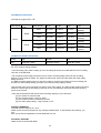
1
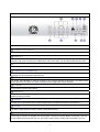
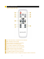
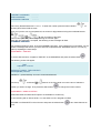
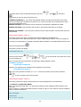
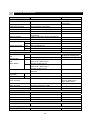
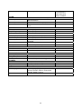
AU-DVRS-04AL
User’s Manual
4-Channel DVR (Digital Video Recorder)
This manual describes the basic operation of this DVR model.
1
GENERAL SAFETY AND PRECAUTIONS
This DVR is manufactured to satisfy international safety standards. Review the following safety
precautions to avoid injury and prevent damage to the DVR or any products connected to it.
1. Use a proper power source. Do not operate this product from a power source that applies more than
the specified voltage (90~260 VAC).
2. Never insert anything metallic into the DVR case - this can cause electric shock.
3. Do not operate in wet & dusty conditions. Keep product surfaces clean and dry.
Avoid placing the DVR in areas like a damp basement or a dusty hallway.
4. Do not expose this product to rain or use near water. If the product gets wet, unplug it and contact an
authorized dealer immediately.
5. To clean the outside case of the DVR, use a lightly dampened cloth (no solvents).
6. The DVR generates heat during operation. Place the DVR in a well-ventilated area. The DVR has a
built-in fan to properly ventilate the system. Do not block air holes (upper&sides) of the DVR case.
7. Do not operate with suspected failures. If there are any unusual sounds or smells coming from
the DVR, unplug it immediately and contact an authorized dealer or service center.
8. Do not attempt to remove the top cover.
Warning: Removing the DVR’s cover can cause severe electrical shock.
9. Handle DVR box carefully to avoid damaging the product. If you accidentally drop your DVR on any
hard surface, it may cause a malfunction. If the DVR doesn’t work properly due to physical damage,
contact an authorized dealer for repair or exchange.
10. Use standard lithium cell battery. (NOTE: Manufacturer has preinstalled battery.)
The standard lithium cell 3V battery located on the mother board should be replaced if the time clock does
not hold its time after the power is turned off.
Warning: Unplug the DVR before replacing battery or you may be subjected to severe electrical shock.
Properly dispose of old batteries.
Caution: Risk of explosion if battery is replaced by an incorrect type. Do not discard lithium batteries into
the trash can or into fire. Dispose in accordance with local waste regulations.
11. You must use this DVR with AC adapter for DC power. Use only the AC adapter that is supplied.
Information to user
The user’s manual or instruction manual for an intentional or unintentional radiator shall caution the
user that changes or modifications not expressly approved by the party responsible for compliance
could void the user’s authority to operate the equipment.
Note: This equipment has been tested and found to comply with the limits for a Class A digital
device, pursuant to part 15 of the FCC Rules. These limits are designed to provide reasonable
protection against harmful interference when the equipment is operated in a commercial
environment. This equipment generates, uses, and can radiate radio frequency energy and, if not
installed and used in accordance with the instruction manual, may cause harmful interference to
radio communications. Operation of this equipment in a residential area is likely to cause harmful
interference, in which case the user will be required to correct the interference at their own expense.
2
TABLE OF CONTENTS
Chapter 1: Overview of this DVR
OVERVIEW OF THIS DVR
06
Chapter 2: Getting To Know Your DVR
DVR FRONT PANEL
06
DVR BACK PANEL
08
Chapter 3: Remote Controller
REMOTE CONTROLLER PANEL
10
Chapter 4: Getting Started
OVERVIEW OF SET UP PROCEDURES
11
Chapter 5: Hardware Installation
HARD DISK DRIVE INSTALLATION
12
CONNECTING THE DVR TO YOUR TV SET OR MONITOR
13
CAMERA INSTALLATION
13
SENSOR/ MOTION DETECTOR INSTALLATION
15
ALARM INSTALLATION
15
LAN-DVR CONNECTION
16
POWER CONNECTION
17
Chapter 6: DVR Menu
MAIN MENU
18
CAMERA SELECT
18
RECORD SELECT
19
RECORD MODE
19
RECORD FRAME RATE
19
VIDEO QUALITY
20
RECORD SCHEDULE
20
SUB MENU
21
(1) PASSWORD CHANGE
(2) TIME SET
(3) AUDIO CONTROL
(4) VIDEO SYSTEM
(5) LANGUAGE SELECT
21
22
22
23
23
HARD DRIVE SETUP
23
HARD DRIVE FORMAT
24
SENSOR / MOTION SETUP
25
NETWORK SETUP
26
3
Controlling Playback, Viewing and Record View:
PLAYBACK CONTROL BY TIME SEARCH
28
VIEW CONTROL DURING PLAYBACK
30
RECORD VIEW CONTROL
31
RESET TO FACTORY DEFAULT SETTINGS
31
Chapter 7: Trouble Shooting Guide
TROUBLE SHOOTING
32
Appendix:
TECHNICAL SPECIFICATIONS
34
RECORDING TIME TABLE
36
PRODUCT WARRANTY
36
TECHNICAL SUPPORT
36
Network Viewer Manual
37
Remote DVR Client 2.5 Operation Manual
HDD PC Viewer Manual
59
DVR HDD PC Viewer Operation Manual
4
Chapter 1: Overview of this DVR
OVERVIEW OF THIS DVR
This DVR is a Digital Security System designed to record/retrieve up to 4 channels of video at the same
time. It adopts a digital image compression technology to compress the input channel video streams, and
uses a hard disk to record the compressed video stream. Please refer to the following chapters for set up
and usage instructions:
• Chapter 5 - HARDWARE INSTALLATION explains how to install the DVR and other accessories in your
home.
• Chapter 6 - DVR MENU explains how to operate/manage the DVR.
This DVR models covered in this manual feature the same user interface.
Chapter 2: Getting To Know Your DVR
DVR FRONT PANEL
This chapter briefly describes the button functions on DVR front panel. Buttons are used to operate the
DVR’s basic functions, such as recording, playback, fast-forward, reverse, etc. For more details on the
set-up and operation of the DVR, refer to Chapter 6 - DVR MENU.
RECORD
Press RECORD button to record. This button is changed red if DVR starts recording.
RX / TX
This light indicates the DVR unit is connecting with network.
POWER
This light indicates the DVR unit is powered up.
MENU
To display the on-screen menu, press the MENU button.
STOP
To stop playback or recording, press the STOP button. When you press the STOP button while the
DVR is recording.
SEL (SELECT)
5
Use the SELECT button to confirm a menu option or value in a menu field.
ALL-CH1-CH2-CH3-CH4
This SEL button allows you to select camera images in live recording or playback mode. The
default display setting of the DVR is set to “ALL” which displays all 4 channels of video at the same
time. The following options are available for displaying video images on your monitor:
ALL: Displays all 4 channels of video in quad screen mode
1-2-3-4: Displays each channel of video individually in full screen mode.
For more information on selecting channels, see Chapter 6 - CAMERA SELECT.
: PAUSE
To pause video playback, pres s the PAUSE button. Then the video displaying will be stopped. To
continue playback, push the PLAY button.
: FF
To playback recorded video faster, press the FAST FORWARD button.
There are three levels of fast forward playback speed. Pres s FF button 1 time: Video plays two
times faster (x2) than the normal play. Press FF button 2 times: Video plays three times faster (x3)
than the normal play.
Press FF button 3 times: Video plays four times faster (x4) than the normal play. To change the
fast forward play back speed level, pres s the FAST FORWARD button again.
: REW
To play recorded video backward, press the REVERSEPLAYBACK button. The fast forward and
reverse playback speeds
will vary depending on the frame rate and record quality settings , as well as the number of
channels recorded.
: PLAY
After recording, pres s the P LAY button to s tart video playback. P layback will s tart with the
oldest unread event and then continues playing sequentially through the contents on the hard disk
drive. If there is no unread event, then it plays the latest recorded video. For more detailed
information about playback by Time Search function, refer to Chapter 6 – Playback control by time
search.
: UP / DOWN
To change a menu field or change the DVR configuration values, use the UP and DOWN buttons.
6
DVR BACK PANEL
For more details on installation, refer to Chapter 5 - Hardware Installation.
POWER ON/OFF SWITCH
Use this button to turn on or off the DVR.
VIDEO OUT
Connect the DVR to a TV or monitor using a BNC cable. You can connect two monitors or TVs to the
DVR unit. And if you connect one of VIDEO OUT ports to the VCR, you can backup data with the VCR.
LOOP OUT (BNC )
These are loop output of camera input.
CAMERA IN (or CHANNEL IN)
Connect cameras to the DVR. Each channel port (1, 2 , 3, 4) is for a single camera connection. A total of
4 cameras can be connected to the DVR unit.
SENSOR TERMINAL BLOCK
The sensor terminal block is used to connect up to 4 motion sensors to the DVR. If you add motion
sensor devices to your DVR, the video recording can be triggered by motion detection.
ETHERNET
This is used to connect with network.
AUDIO OUT
Connects the DVR to the AUDIO IN port on your TV so that you can hear recorded sound from TV
speakers through the DVR.
AUDIO IN
Use this port to connect the DVR to cameras that have a microphone function to record sound.
ALARM
The alarm output terminal is used to install a single alarm device.
AC 12V/5A (AC-DC POWER ADAPTER JACK)
This is used to connect AC adapter jack for DC power. Connect the power adapter to the DVR. Use only
the AC adapter that comes with the unit. This DVR contain a power supply that is enclosed in the unit.
7
The following features are found on this DVR
LAN
Connect the DVR to your computer or routing device such as a DSL modem or hub using a LAN cable
for remote viewing.
LAN Port
The LAN (RJ-45) jack is used to connect the DVR to a Local Area Network. This allows you to control the
DVR for remote viewing via the internet.
8
Chapter 3: Remote Controller
REMOTE CONTROLLER PANEL
CH1/ CH2/ CH3/ CH4/ ALL: The buttons to s elect channels.
REC: The button to start recording.
STOP: The button to stop playback or recording.
PLAY: The button to s tart video playback.
FF: The button to playback-recorded video faster.
REW: The button to play recorded video backward.
PAUSE: The button to pause video playback.
MENU: The button to display the on screen menu.
UP/ DOWN: The buttons to choose a menu field.
SELECT: The button to choose or change a menu option or values in a menu field.
9
Chapter 4: Getting Started
OVERVIEW OF SET UP PROCEDURES
Below is an overview of the installation steps required get your DVR unit working.
Each step is explained in detail in Chapter 5 - Hardware Installation.
(1) Install a hard disk drive.
(2) Connect the DVR to a TV set or monitor.
(3) Connect cameras (up to 4) to the DVR.
(4) Connect optional accessories (sensors or alarm).
(5) Connect the LAN cable between DVR and network switch or router.
(6) Connect the power.
(7) Turn the power on.
(8) Start TV Monitoring and recording.
General Operating Advice:
● Make sure that a hard disk drive and at least one camera is properly installed
(See Chapter 5 -Hardware Installation)
● The hard disk jumper setting must be set to master (Refer to Chapter 5 - Hard Disk Drive Installation for
more information.) Otherwise, the DVR may not recognize the hard drive.
Note: The default of the hard disk jumper setting is set to master.
● The firmware used in this DVR is compatible with your computer’s operating system (i.e. Windows).
Therefore, you can take the hard drive from this DVR and install it in your computer to view recorded
video. (Refer to the HDD PC Viewer manual.)
● This DVR offers you the flexibility to choose a recording frame rate (maximum rate: 30 frames per
second). A faster frame rate provides a more natural motion in recorded video and require more hard
disk drive storage space. You may reduce the frame rate (minimum rate: 1 frame per second) to fit longer
recording sessions on your hard disk. Refer to the Recording Time Table on page 36 for more information.
● The default setting for cameras during the initial power up of your DVR is set to 1 2 3 4(all camera).
You will see a blue screen in quad mode with no camera images (refer to page 18 for instructions on how
to select cameras for viewing and recording). When the DVR starts up, it enters the default operational
state: VIEW mode. In this mode the DVR does not record or play the recorded stream, it just shows the
current images from each camera connected to the DVR.
● The default recording setting for most this DVR is set to EACH mode, 30 frames per second and normal
video quality. If you select four cameras to record using a 120GB hard drive (HDD), you should be able to
record for about four to five days (at 30 frames per second). This is an approximate estimate. Refer to the
Recording Time Table on page 36 for more information.
● There is an exception to entering the VIEW mode at start up. If the power is turned off while recording
(i.e. a power failure), the DVR will enter POWER RECOVERY mode at start up and detect that it has been
shut down by a power failure, it will then reinitiate the recording process.
Refer to Chapter 5 - Hardware Installation for more information on installation procedures.
10
Chapter 5: Hardware Installation
HARD DISK DRIVE INSTALLATION
Check to verify the hard drive’s jumper setting.
Important:
The jumper setting must be set to "master". Check the
jumper setting diagram on your hard drive or consult your
hard drive manual for instructions.
Note: The default setting of hard disk drive is set to
“master”.
Firmly connect the ribbon cable (IDE cable) & power cable
to the hard drive interface and carefully put the hard drive
into the HDD rack.
Fasten the hard drive to the hard drive rack using the
supplied screws.
For more information about the hard disk drive jumper settings,
visit the web sites of major HDD manufacturers:
Western Digital
http://support.wdc.com/techinfo/general/jumpers.asp
Maxtor
http://www.maxtor.com/en/documentation/installation_guides/ata_installation_guide.pdf
Seagate
http://www.seagate.com/support/kb/disc/ref/jumper_settings.html
IBM
http://www-3.ibm.com/pc/support/site.wss/document.do?lndocid=GSMH-3FCCKZ
Hitachi
(http://www.hgst.com/hdd/support/jumpers.htm)
Fujitsu
http://www.fujitsu.com/support/computing/storage/hdd/eol/dhdd/
11
CONNECTING THE DVR TO YOUR TV SET OR MONITOR
Video Input/Output Connection (For TV / monitor screen display)
To display the DVR’s picture, the video output signal need to be transferred to your TV set or monitor.
Any TV set that has a VIDEO INPUT terminal is suitable for displaying the picture. The figure above
shows the video signal line connection.
Using an BNC cable, connect the VIDEO IN terminal of your TV to the VIDEO OUT terminal of your DVR
rear panel.
Note: The BNC cable required for this connection does not come packaged with the DVR.
Audio Input/Output Connection (For TV / monitor speaker)
Using an RCA cable, connect the AUDIO IN terminal of your TV / monitor to the AUDIO OUT terminal of
your DVR rear panel.
Note: The RCA cable required for this connection does not come packaged with the DVR .
CAMERA INSTALLATION
For cameras that do not have a built-in microphone
using an BNC cable, connect cameras to the VIDEO IN or CHANNEL IN terminal on the back panel of
your DVR. Next, plug in the camera power adapter.
Connection Type 1 – For indoor/outdoor cameras to use a splitter cable
12
Connection Type 2 – For cameras that have a VIDEO OUTPUT terminal on the rear panel of the
camera body.
For cameras that have a built-in microphone
If you would like to install cameras that have a built-in microphone, follow the diagram below for
installation.
Connection Type 1 – For cameras that have a video/audio splitter cable.
Connection Type 2 – For cameras that have video/audio terminals on the rear panel of the camera
body.
13
SENSOR/ MOTION DETECTOR INSTALLATION
You can connect up to 4 motion sensors (not included in the DVR package) to the DVR.
There are two steps to install sensors.
1. Connect the sensor signal lines to the signal input terminal.
2. Connect the sensor power lines to the appropriate power source.
In general, there are three different types of sensors available. They are:
(1) NORMAL-CLOSE
(2) NORMAL-OPEN
(3) NOT INSTALLED
Refer to the diagram below for information on how to connect each type of sensor to the DVR.
General Operating Advice When Using Sensors
● After you install sensor(s), the programmed recording mode must be set to "S" for "sensor" during the
hour that you are recording (Refer to Chapter 5 – Record Schedule Setup for more information).
● If the DVR is set to QUAD mode and a sensor trips, all of the selected cameras will record. However, if
you are in EACH mode and a sensor trips, only the corresponding camera will record (i.e. sensor one
corresponds with camera one).
● Contact an authorized dealer for information about buying the appropriate sensors for your needs and
for information concerning proper installation procedures.
ALARM INSTALLATION
The DVR has an internal switch for sounding an alarm. When a sensor is triggered, the alarm is activated
as well.
There are two steps to install an alarm.
1. Connect the alarm power lines to the alarm switch terminal.
2. Connect the alarm power lines to the appropriate power source.
Refer to the diagram below for information on how to connect an alarm to your DVR.
14
Note: Contact an authorized dealer for information about buying the appropriate alarm for your needs
and for information concerning proper installation procedures.
LAN-DVR CONNECTION
You can connect your DVR to a local area network or to the internet. See the diagram below to make the
LAN connection. For remote viewing from your computer, you must have a LAN connection or Internet
access to use this feature.
Refer to Chapter 6 - NETWORK SETUP for information on how to set up the DVR for remote controlling.
Note: Suitable network routers and switches are available from Net gear, D Link, or Linksys. Your
internet connection requires a dedicated static IP address from your DSL provider and port forwarding
capability on your router.
15
POWER CONNECTION
Connect the power adapter to the power adapter jack located at the rear panel of the DVR unit.
Now, the DVR is ready to run! Turn on the power button at the rear side of the DVR. The next chapter
will explain the about the DVR menu and how to operate your DVR.
16
Chapter 6: DVR Menu
MAIN MENU
In order to select cameras for recording, set recoding quality, schedule recording times and to set other
operation parameters, you will need to access the DVR’s menu.
To access the DVR’s main menu, press the menu button
see the following screen on the monitor connected to the DVR.
on the DVR’s front panel. You will
MAIN MENU
> CAMERA SELECT
1234
RECORD SELECT
1234
RECORD MODE EACH
RECORD FRAMERATE
30
VIDEO QUALITY
NORMAL
RECORD SCHEDULE
SUB MENU
HARD DRIVE SETUP
SENSOR / MOTION SETUP
NETWORK SETUP
PRESS (UP, DOWN) , THEN (SELECT)
PRESS (MENU) TO EXIT
In the main menu, the arrow indicator > will be shown on the screen to the left of the menu listings menu
selections. Press the UP
or DOWN
key on the DVR front panel to move the arrow
sign > up or down in order to navigate to the menu selection desired.
You can also use this function via network.
CAMERA SELECT
To select cameras for viewing on your monitor, navigate to CAMERA SELECT.
Then, use the buttons
monitor screen.
on the DVR’s front panel to select a camera for real-time viewing on the
MAIN MENU
> CAMERA SELECT
1234
You can also press the select button
for different combinations of camera viewing. For example,
• When you choose ( - - - - ), all cameras will be disabled.
• When you choose (1 2 3 4), all cameras will be operational.
• When you choose ( - - - 4 ), only camera 4 will be operational.
• When you choose (1 2 - 4), cameras 1, 2, and 4 will be operational.
There are 16 different combinations of camera viewing settings.
Note: When viewing in quad screen mode, the following diagram shows where each camera is displayed
on the monitor connected to the DVR.
17
RECORD SELECT
To select cameras for recording, navigate to RECORD SELECT.
Then, use the buttons
on the DVR’s front panel to select a camera for recording.
MAIN MENU
CAMERA SELECT
1234
> RECORD SELECT
1234
You can also press the select button
for different combinations of camera recording. For
example,
• When you choose (- - - -), no cameras will record.
• When you choose (1 2 3 4), all cameras record.
• When you choose (- - - 4), only camera 4 will record.
• When you choose (1 2 - 4), cameras 1, 2, and 4 will record.
There are 16 different combinations of camera record settings.
Note: Only the selected camera(s) will record real-time events during recording period.
RECORD MODE
To select a recording mode, navigate to RECORD MODE.
Then, press the select button
MAIN MENU
CAMERA SELECT
RECORD SELECT
> RECORD MODE
to choose either EACH or QUAD mode.
1234
1234
EACH
When recording with 4 cameras in QUAD mode, you will view the most natural movement on playback.
EACH mode supports higher quality recording at a reduced frame rate.
Example: EACH mode + 4 cameras + 30 frames per second = each camera will record at approximately.
7.5 frames per second.
RECORD FRAME RATE
To select frame rate of cameras to record, navigate to RECORD FRAME RATE.
Then, use the select button
to choose the desired frame rate for recording.
18
MAIN MENU
CAMERA SELECT
1234
RECORD SELECT
1234
RECORD MODE
EACH
> RECORD FRAMERATE
30
The factory default setting is 30, which means the DVR records at the speed of 30 frames per second.
The higher the record frame rate, the more natural motion will be displayed on the screen for playback.
The lower the record frame rate, the more space you will save on the hard disk drive. There are different
record frame rate settings to choose from (between 30 frames and 1 frame per second).
VIDEO QUALITY
To choose the video quality for recording, navigate to VIDEO QUALITY.
Then, use the select button
to choose either LOW, NORMAL or HIGH. SELECT
MAIN MENU
CAMERA SELECT
1234
RECORD SELECT
1234
RECORD MODE
EACH
RECORD FRAMERATE
30
> VIDEO QUALITY
NORMAL
The higher the video quality, the clearer the image will be during playback. The lower the video quality,
the more space you will save on the hard disk drive.
Note: The video quality in View Mode is not affected by the video quality setting.
These settings only affect the video quality during playback of recorded video.
RECORD SCHEDULE
To schedule recording a specified times throughout the day, navigate to RECORD SCHEDULE.
MAIN MENU
CAMERA SELECT
1234
RECORD SELECT
1234
RECORD MODE
EACH
RECORD FRAMERATE
30
VIDEO QUALITY
NORMAL
> RECORD SCHEDULE
Then, press the select button
to display the following menu:
PROGRAMMED RECORD
PRESS (UP, DOWN) , THEN (SELECT)
PRESS (MENU) TO EXIT
The numbers below indicate the hours of the day based on a 24-hour clock. The first “T” on the left is
equal to the first hour of the day (12 midnight through 1:00 am). The next "T" equals the second hour of
the day (1:00 am – 2:00 am), and so on.
19
Press the up
or down
desired time selection.
button on the DVR’s front panel to move the arrow V to the
Then press the select
button to change between continuous recording (T), sensor recording (S)
and no recording (--) for the selected time slot.
(T) System will record continuously during this period.
(S) System will record when sensor or motion is triggered.
Refer to SENSOR/ MOTION SETUP on page 25 to setup a sensor/ motion detector.
(--) System will not record during this period.
* You can see indication of (T), (S), (--) on viewing screen.
Once you have finished, press the menu
Note: You must press the record
button to exit.
button to start a recording session.
SUB MENU
To change a password, set the time for your DVR, or to turn audio recording on or off, navigate to SUB
MENU.
MAIN MENU
CAMERA SELECT
1234
RECORD SELECT
1234
RECORD MODE
EACH
RECORD FRAMERATE
30
VIDEO QUALITY
NORMAL
RECORD SCHEDULE
> SUB MENU
Then, press the select
button to display the following menu:
SUB MENU
> PASSWORD CHANGE
TIME SET
AUDIO RECORD
AUDIO MUTE
VIDEO SYSTEM
LANGUAGE SETUP
ON
OFF
NTSC
ENGLISH
PRESS (UP, DOWN) , THEN (SELECT)
PRESS (MENU) TO EXIT
(1)SUB MENU - PASSWORD CHANGE
To change a password, navigate to PASSWORD CHANGE in the SUB MENU and press the select
button
The following screen will appear:
20
CURRENT PASSWORD
NEW PASSWORD
PASSWORD CONFIRM
:-----:-----:------
The Factory Default Password is 111111. To enter this number press the button labeled 1
the front panel of the DVR six times.
on
Once you input the your current password, set a new six digit password using the numbered buttons
on the front panel of the DVR.
,
,
,
Then, confirm your new password by entering the number again.
When the new password is accepted, the following screen message will flash:
PASSWORD CHANGED
The message will blink 3 times. Then the SUB MENU will return. If the password is not accepted, you will
receive a message that informs you that it was not accepted and the SUB MENU returns. You may try
again by repeating the same steps.
(2)SUB MENU - TIME SET
To set the date and time, navigate to TIME SET in the SUB MENU and press the select button
The following screen will appear:
TIME
2004/02/17 19:44:32
^
PRESS (UP, DOWN) , THEN (SELECT)
PRESS (MENU) TO EXIT
2004/02/17 = year/month/day 19:44:32 = hour/minute/second
Use the up
and down
buttons on the front panel to move the arrow ^below the
number you wish to change. Then press the select button
to change the numeric values.
(3)SUB MENU - AUDIO CONTROL
AUDIO RECORD & AUDIO MUTE options are available for models only.
To set recording with or without audio, or to set audio to mute, navigate to AUDIO
RECORD or AUDIO MUTE in the sub menu and press the select button
or off.
21
to turn these features on
SUB MENU
> PASSWORD CHANGE
TIME SET
AUDIO RECORD
AUDIO MUTE
VIDEO SYSTEM
LANGUAGE SETUP
ON
OFF
NTSC
ENGLISH
PRESS (UP, DOWN) , THEN (SELECT)
PRESS (MENU) TO EXIT
When you move the arrow to AUDIO RECORD and push the select
changed to ON or OFF.
button, the option will be
If the option is ON then the audio will be recorded onto the hard drive when you push RECORD
button.
When you move the arrow to AUDIO MUTE and push the select
button, the option will be changed
to ON or OFF. If the option is ON then the speaker output at DVR box will be mute. Even though this
option is OFF, the recording of audio depends upon the AUDIO RECORD option.
Note: When you do audio recording, you have to set the RECORD FRAMERATE over 4. If you set under
4(1,2or 3), you can’t do audio recording.
(4)SUB MENU - VIDEO SYSTEM
Navigate to VIDEO SYSTEM and press the select
button. Built-in Auto Detection for NTSC / PAL
(5)SUB MENU - LANGUAGE SELECT
At the Sub Menu
1. Press the button. The language select menu screen appears.
2. Press the select button, and than you can choice 8 languages
(English, Japanese, Chinese, Korean, German, Portuguese, Spanish, Danish, French)
HARD DRIVE SETUP
To setup your hard disk drive, navigate to HARD DRIVE SETUP in the main menu and press the
select
button.
The following screen will appear:
HARD DRIVE SETUP
> OVERWRITE ENABLED
[YES]
HARD DRIVE SIZE
120000 MB
HARD DRIVE USED
101208 MB
HARD DRIVE FORMAT
88 %
PRESS (UP, DOWN) , THEN (SELECT)
PRESS (MENU) TO EXIT
22
To navigate and to make the desired selections use the up
down
and select
buttons on the front panel of the DVR unit.
OVERWRITE ENABLED: If you choose YES (default setting), recording continues and over writes
previous recording when hard disk drive space is full. If you choose NO, the recording session stops
when all hard disk drive is full.
MASTER HDD SIZE: This shows the size of the primary hard disk drive installed in the DVR.
MASTER HDD USED: This shows the space used on the first hard disk drive for recording.
MASTER HDD FORMAT: If you format the hard drive, all the data recorded on the first hard disk drive
will be erased.
HARD DRIVE FORMAT - PART A
The following instructions apply to DVR that came packaged with a hard disk drive.
If your DVR did not come with a hard disk drive, refer to HARD DRIVE SETUP - PART B on page 24.
To format your hard disk drive, navigate to MASTER HDD FORMAT in the HARD DRIVE SETUP menu
and press the select button
The following screen will appear:
PASSWORD INPUT (6) : _ _ _ _ _ _
Use the numeric buttons
the correct password.
,
,
,
on the front panel of the DVR unit to enter
When you enter the correct password, the following message will flash 3 times.
PASSWORD CORRECT
HARD DISK FORMATTED
Otherwise, the following error message will be displayed on the screen.
PASSWORD INCORRECT
Note: The Factory Default Password is 111111. To enter this number press the button labeled
1
,
on the front panel of the DVR six times.
HARD DRIVE FORMAT - PART B
The following instructions apply to DVR that did not come packaged with a hard disk drive.
1. TO INSTALL A HARD DISK DRIVE:
When you install a hard disk drive, you will see the following screen displayed while the DVR unit is
booting up:
Refer to chapter 5- HARD DISK DRIVE INSTALLATION on page 12 of this manual or Quick installation
guide to install hard disk drive.
HDD CHECKING ……
HARD DVIVE
HDD MODEL NUMBER
23
SENSOR/ MOTION SETUP
To set up recording that is activated by a motion sensor connected to the DVR, navigate to SENSOR
SETUP
MAIN MENU
CAMERA SELECT
1234
RECORD SELECT
1234
RECORD MODE
EACH
RECORD FRAMERATE
30
VIDEO QUALITY
NORMAL
RECORD SCHEDULE
SUB MENU
HARD DRIVE SETUP
> SENSOR / MOTION SETUP
Then, press the select button
to display the following menu: SELECT
SENSOR / MOTION SETUP
> SENSOR/ MOTION RECORD TIME
ALARM OUT TIME
SENSOR TYPE
CH-1
NOT INSTALLED
CH-2
NOT INSTALLED
CH-3
NOT INSTALLED
CH-4
NOT INSTALLED
10
00
MOTION
LEVEL4
LEVEL4
LEVEL4
LEVEL4
PRESS (UP, DOWN) , THEN (SELECT)
PRESS (MENU) TO EXIT
SENSOR / MOTION RECORD TIME: Indicates the time recording period after the sensor or motion’s
last detection of movement.
ALARM OUT TIME: Indicates how long the alarm lasts after it sets off.
SENSOR / MOTION RECORD TIME and ALARM OUT TIME are measured in seconds.
Note: You must have sensors connected to your DVR unit to use this feature. For more information on
sensors, refer to Chapter 5 – SENSOR/ MOTION DETECTOR INSTALLATION on page 15.
SENSOR / MOTION SETUP (CONTINUED)
There are 3 different modes for sensor activated recording:
1. NOT INSTALLED (no sensors are connected to the DVR unit)
2. TYPE: NORMAL-CLOSE
3. TYPE: NORMAL-OPEN
The type of sensor should be selected to match the type of sensor connected to your DVR. Check the
materials that came with your sensor, or contact the manufacturer to see what type of sensor you have.
To set the mode for sensor activated recording, navigate to each channel and press the select
button
to choose either NOT INSTALLED, TYPE: NORMAL-OPEN, or TYPE: NORMAL-CLOSE.
24
SENSOR/ MOTION SETUP
SENSOR/ MOTION RECORD TIME
ALARM OUT TIME
SENSOR TYPE
>CH-1
NOT INSTALLED
CH-2
NOT INSTALLED
CH-3
NOT INSTALLED
CH-4
NOT INSTALLED
10
00
MOTION
LEVEL4
LEVEL4
LEVEL4
LEVEL4
PRESS (UP, DOWN) , THEN (SELECT)
PRESS (MENU) TO EXIT
In NORMAL-CLOSE mode, if an intruder cuts the cable line that connects the sensor to the DVR, sensor
recording starts automatically. In NORMAL-OPEN mode, if an intruder cuts the cable line that connects
the sensor to the DVR, the sensor recording will not start at all.
MOTION SETUP
There are 5 different modes for sensor activated recording:
1. OFF: No motion direction is connected to the DVR unit.
2. Level 1~4: Level 4 is the most sensitive.
NETWORK SETUP
NETWORK SETUP is available for this DVR.
If you plan to connect your DVR unit to a network, navigate to NETWORK SETUP.
MAIN MENU
CAMERA SELECT
1234
RECORD SELECT
1234
RECORD MODE
EACH
RECORD FRAMERATE
30
VIDEO QUALITY
NORMAL
RECORD SCHEDULE
SUB MENU
HARD DRIVE SETUP
SENSOR / MOTION SETUP
> NETWORK SETUP
Then, press the select button
to display the following menu:
NETWORK SETUP
> ACCEPT CLIENT
[YES]
MAC ADDRESS
00.22.24.23.25.26
IP ADDRESS
192.168.001.090
SUBNET MASK
255.255.255.000
GATEWAY
192.168.991.245
PRESS (UP, DOWN) , THEN (SELECT)
PRESS (MENU) TO EXIT
25
Important! : : The MAC ADDRESS is issued by the manufacturer and should be on a label located on
the network board in your DVR. Keep this number in a safe place for future reference.
If you have a battery failure, replace the on-board backup battery and re-input the MAC ADDRESS.
<How to input MAC ADDRESS>
1. After turning off the power, take off the network board.
2. Move and fix the jumper into the left 2 pins on the center of the main board.
3. After inserting the network board and turning on the power, input the MAC ADDRESS.
4. After turning off the power, take off the network board.
5. Move and fix the jumper into the right 2 pins on the center of the main board.
6. Insert the network board again and cover with the case of the DVR.
If you don’t follow this step, you can’t use Network.
The IP ADDRESS, SUBNET and GATEWAY above are only used for an example. Do not use them for
your NETWORK SETUP.
The IP ADDRESS, SUBNET and GATEWAY are provided by your Internet Service Provider (ISP) when
you setup your account. Keep your ISP account information in a safe place for future reference.
NETWORK SETUP (CONTINUED)
NETWORK SETUP is available for this DVR.
1. When you first open the NETWORK SETUP window, the arrow will be next to ACCEPT CLIENT.
While the arrow is next to ACCEPT CLIENT, use the select button
2. Use the up
and down buttons
NETWORK SETUP menu.
to change the status (YES/NO).
to move the arrow to the other categories in the
3. To change the numbers in MAC ADDRESS, IP ADDRESS, SUBNET and GATEWAY, move the arrow
next to the specific category that you want to change (i.e. IP ADDRESS).
4. When you press the select button
the arrow will move to position B above the category you
have chosen (Refer to the diagram below).
Note: When the arrow moves to position B, the category above will disappear to make room for the
arrow. For example, if you select IP ADDRESS, the arrow moves above the farthest left digit of IP
ADDRESS and MAC ADDRESS disappears.
NETWORK SETUP
> ACCEPT CLIENT
[YES]
\/
IP ADDRESS
192.168.001.090
SUBNET
255.255.255.000
GATEWAY
192.168.991.245
PRESS (UP, DOWN) , THEN (SELECT)
PRESS (MENU) TO EXIT
26
5. Use the up
button
and down buttons
to move the arrow from left to right and use the select
to change the numbers.
6. Once you have finished making your changes, press the menu button
position A (Refer to the diagram above).
The arrow will return to
ABOUT NETWORK SETTINGS:
ACCEPT CLIENT: If the ACCEPT CLIENT option is set as [YES], remote DVR access control is enabled
so you can control your DVR remotely via a LAN connection using the "Remote DVR Client" software
included on CD in the DVR package. If ACCEPT CLIENT option is set as [NO], the Remote DVR Client
will not be able to access your DVR from remote location.
MAC ADDRESS: On a local area network (LAN), the MAC (Media Access Control) address is your
computer's unique hardware identity number. (On an Ethernet LAN, it is the same as your Ethernet
address.) When you are connected to the Internet from your computer (or host as the Internet protocol
thinks of it), a corresponding table relates your IP address to your computer's physical (MAC) address on
the LAN.
IP ADDRESS: Within an isolated network, you can assign IP addresses at random as long as each one
is unique. However, connecting a private network to the Internet requires using registered IP addresses
(called Internet addresses) to avoid duplicates.
The IP address is assigned by your Internet Service Provider (ISP), but you may assign values to the
lowest digits of the address (to designate unique addresses for your DVR, your PC and other devices on
your LAN). Contact your ISP for more information regarding to your own IP address.
SUBNET: This refers to a subnet mask used to determine what subnet an IP address belongs to. A
number that is used to identify a sub network so that IP addresses can be recognized on a local area
network.
GATEWAY: In enterprises, the gateway is the computer that routes the traffic from a workstation to the
outside network that is serving the web pages. In homes, the gateway is usually housed at the ISP. The
gateway connects networks that have different protocols. The gateway address is provided by your ISP.
PLAYBACK CONTROL BY TIME SEARCH
When you press the menu button
during PLAY mode, the SEARCH TIME menu will appear as
shown below. With this menu, you can choose and playback a recorded event or manually input a
specific time for playback.
TO CHOOSE AND PLAYBACK A RECORDED EVENT FROM A LIST:
When you first open the SEARCH TIME window, the arrow will be pointing at the most recent event (01).
1. Use the up
and down
2. Press the PLAY button
buttons to find the event that you want to view.
to start playback of the event you have chosen.
27
SEARCH TIME
HARD DRIVE: MASTER
04/05/21 06:59:59 – 04/05/21 06:59:59
> 01 TIME
02 TIME
03 TIME
04 TIME
05 SENSOR
2004/05/21
2004/05/21
2004/05/20
2004/05/20
2004/05/20
(UP, DOWN) MOVE
(MENU) EXIT
01:15:20
00:25:33
11:35:55
10:48:12
09:57:55
(PLAY) PLAY
(FF) SELECT EVENT OR TIME
04/05/21 = year/month/day
06:59:59 = hour/minute/second
Note: When the arrow is pointing at a specific event, the date and time shows the beginning (date and
time) to the ending (date and time) of that recorded event.
Note: While “playback” mode, the red record light blinks.
TO MANUALLY INPUT A SPECIFIC DATE AND TIME FOR PLAYBACK:
1. Press the play button
to access the SEARCH TIME menu. The arrow will be next to the most
recently recorded event (Position A shown below).
on the front of your DVR. The arrow will move next to HARD DRIVE:
2. Press the FF button
MASER (Position B shown below).
3. Press the down button
and the arrow will move below the date and time references listed
under HARD DRIVE: MASER (Position C shown below). The date and time displayed under HARD
DRIVE: MASER corresponds with the beginning and
ending period of what has been recorded on your hard drive.
4. Move the arrow left or right by using the up
and down
buttons.
5. Change the date and time digits by pressing the select button
6. Finally, input the desired starting date and time, press the play button
playing.
28
and the DVR will start
SEARCH TIME
> HARD DRIVE: MASTER
03/05/21 06:59:59 – 03/05/21 06:59:59
∧
>
01 TIME
02 TIME
03 TIME
04 TIME
05 SENSOR
2004/05/21
2004/05/21
2004/05/20
2004/05/20
2004/05/20
(UP, DOWN) MOVE
(MENU) EXIT
01:15:20
00:25:33
11:35:55
10:48:12
09:57:55
(PLAY) PLAY
(FF) SELECT EVENT OR TIME
VIEW CONTROL DURING PLAYBACK
If you have set the RECORD MODE to EACH (see page 19), you can use the select
button on the
DVR front panel to select the camera that you want to view in full screen during playback.
CH1- If you press the select
screen.
button once, you can see camera1 in full
CH2- If you press the select
screen.
button twice, you can see camera2 in full
CH3- If you press the select
in full screen.
button three times, you can see camera3
CH4- If you press the select
full screen.
button four times, you can see camera4 in
ALL- If you press the select
in full screen.
button five times, you can see all cameras
Quad screen: Images from all 4 cameras are displayed at the same time in 4 separate
sections on a single screen.
Note: You cannot view individual cameras in FULL SCREEN display while in QUAD mode. You can only
view a quad screen when the RECORD MODE is set to QUAD (see page 19).
29
RECORD VIEW CONTROL
When you have finished entering all of the settings in the DVR menu and the record button
is
pressed, the recording process starts immediately. In the example below, the recording channel
indicators n next to CH1 and CH2 indicate that those channels have been selected to record. CH3 and
CH4 are not recording.
RESET TO FACTORY DEFAULT SETTINGS
To reset the DVR settings back to the factory default, press the pause button
5 times.
After resetting, the password will return to the default value (111111) and all DVR settings on the menu
will return to default.
Reset to factory default will not erase any video data on the hard disk drive.
30
Chapter 7: Trouble Shooting Guide
TROUBLE SHOOTING
1. What kind of camera should I buy for this DVR ?
Any BNC or RCA interface indoor/outdoor/infrared camera will work with the DVR. It doesn’t matter
whether it’s a color or black/white camera. However, web cameras that require a USB interface are not
compatible with this DVR.
2. What kind of sensor device should I buy for sensor recording?
Any motion detection sensor will be compatible with this DVR.
3. What kind of alarm device should I buy for the DVR?
Most DC-powered alarms are compatible with this DVR.
4. I can’t turn on the DVR.
Make sure that the power switch is on. If the power switch is on and you still can’t turn on DVR, make
sure that the power cord is plugged in correctly and the green power light on DVR front panel is on.
5. I see nothing but a blue screen after I turn on the DVR.
Check the camera input and video output connection on the DVR rear panel. If you can’t find any
problem with these connections, check whether the camera power cable is firmly connected.
6. I pushed the menu button but it doesn’t show the menu directory.
When the DVR is in record mode no button on the front panel will work. The red light below REC button
is on when DVR is recording. To end recording, press the STOP button.
7. I see an HDD error message on the screen.
If you see the error messages such as "Hard Disk Check Fail", "HDD BUSY Error", "HDD DRDY Error",
"HDD initial is Error", pull out and put in the hard disk drive or replace the hard disk. Also make sure that
hard disk rack is firmly locked.
8. I push record button but nothing records.
Make sure that there are no slash ( -- ) signs on Record Schedule Menu. If you see any slash ( -- ) signs,
change it to "T" sign using select button. Or change it to "S" sign if there are any sensors installed on the
DVR and you prefer motion sensor recording.
9. I turn on the DVR and no buttons work.
Check if the hard disk rack is firmly locked. You will see a green light on the DVR side panel when DVR
is locked turned on. Also, make sure hard disk drive jumper is set as a "master". If none of the above
work, check the two connectors (power cable & IDE cable) from hard disk drive to DVR to see if they are
firmly connected.
10. I can’t make each channel to display in full screen.
Make sure that record mode setting is on EACH mode. If it’s on QUAD mode, switch to EACH mode in
the DVR’s main menu.
11. I installed only one camera to channel 1 but the channel 1 screen does not show anything.
Under Menu and Camera Select, select 1.
12. Can I record everything 24 hours 7 days a week without stopping?
Yes. In the Record Schedule Menu, select "T" for all time periods.
13. Can I prevent other people from stopping the recording while I am gone?
Would creating a password do it?
The only way to prevent this is to place the DVR in a room where nobody else can enter.
14. Can I still record all the events while I review the previous recording?
No. The DVR doesn’t support recording during playback.
31
15. How long is the warranty period?
One year after the date of purchase. We will gladly offer replacement for all defective units.
16. What is the correct jumper setting for using a single hard disk drive?
Single master without slave. Most of HDD drives come with the jumper setting as a master without slave
so you may not need to change the jumper setting after you purchase HDD and install it into DVR. Check
the documentation that came with your hard drive.
17. Can I install two hard drives in the Safe Home DVR?
No. Our product supports just one hard disk drive bay.
18. What is the limitation of the hard disk drive size that I can install in the DVR?
The hard drive capacity varies according to the model number of your DVR. Please refer to the
packaging, which your unit was purchased for information regarding the specific hard drive capacity of
your model.
19. How can I erase all data on the hard disk drive?
Select the HDD Format option in the Hard Drive Setup menu.
20. Why do I need a password?
You need a password to format hard disk drive. The password is for your protection.
21. I forgot my password. What should I do?
Press the "Pause" button five times and it will reset DVR settings to factory default. The password will
reset to the factory default of (111111).
22. Can my desktop PC read the video data on hard disk drive in DVR?
The file format used on DVR is not supported by any PC operating systems, including Windows or Linux,
so you can’t access DVR hard disk drive using your PC.
But if you use the exclusive viewer, you can access DVR hard disk drive using your PC. The software for
the HDD PC viewer is in CD to come with DVR.
23. What happens if I install my PC hard disk drive into the DVR?
You can use a PC hard disk drive in the DVR. However, once it runs in DVR, it will delete any PC
operating system and files on the hard disk drive.
24. What kind of hard disk drive should I purchase to make the DVR run?
Any PC compatible IDE, ATA hard disk drive will work.
25. Does the DVR come with sensors, cameras, or hard disk drive?
Some models come with a hard disk drive and cameras. Some models don’t. Please check the package
content information on DVR box or "This DVR models" table in Chapter 1. If the DVR unit that you’ve
purchased contains a digital video recording system only, then you need to buy accessories separately
to complete a digital video recording surveillance system. A single hard disk drive and a single camera
are minimum requirements to make a digital surveillance system complete.
26. What is the capacity to record?
It depends on the installed hard disk drive storage size. In general, you can record up to 6 months with a
120 GB HDD
27. Does this DVR come with a remote control?
Yes. The DVR kit can support remote control.
32
TECHNICAL SPECIFICATIONS
ITEM
DESCRIPTION
REMARKS
VIDEO
Video Input Format
NTSC / PAL
AUTO
FUNCTION
Operating system
RTOS in firmware
Video Input Channels
4CH Composite video (BNC)
Video Output Channels
2CH Composite video (BNC)
Loop Through Output
4CH Composite video (BNC)
Input Level
Main TV Output 1
1.0Vp-p +/-10% Composite, 75 Ohm
Unbalanced
1.0Vp-p Composite, 75 Ohm Unbalanced
Main TV Output 2
1.0Vp-p Composite, 75 Ohm Unbalanced
Display Resolution
Display frame rate
DETECTION
NTSC
720 x 480
PAL
720 x 576
NTSC
Max 120 frames/ sec
4 x 30 frames/ sec
PAL
Max100 frames/ sec
4 x 25 frames/ sec
Screen Split Control
1/4 Screen
RECORDING
Recording frame
rate
(Quad mode)
Recording frame
rate
(Each Mode)
NTSC
Max 30 fps (Quad)
30 fps (per recording CH)
PAL
Max 25 fps (Quad)
25 fps (per recording CH)
NTSC
NTSC
Max 7.5 fps (Each mode)
Each mode = MAX frame /
Number of video source
Max 6.25 fps (Each mode)
Each mode = MAX frame /
Number of video source
Manual / Programmed / Sensor / Motion
Detection
320 x 112, 640 x 224
PAL
320 x 136, 640 x 272
PAL
Recording Mode
Recording
Resolution
Compression format
(Each channel)
Modified JPEG (12-20Kbytes / frame)
Scheduling
Set up per hour
Alarm Out Time
00,05,10,15,20,25,30, CONT
Internal EIDE Storage
Max 1HDD
Quad: 640 x 224 (Total)
Each Channel : 640 x 224
Low: 12KB / frame
Normal: 15KB / frame
High: 20KB / frame
Max 1TB
AUDIO
Compression
ADPCM
Input Channel
1CH (Connectable to any video channel)
Input Level
200mVp-p @ 20KOhm
Live Output
1CH
SEARCHING & PLAYBACK
Searching Method
Time / Event
NETWORK
Monitoring Environment
Client S/W
Dynamic IP server
33
Connection
Supporting 1 Client
FUNCTION:
-Live Monitoring
-HDD Searching
-Setup Available
ALARM
Sensor Input
Alarm Output
* Motion Detection
4 Port / NC or NO Non-isolated TTL input
Ground Common
1Port / NO Isolated Relay Output
Available for each camera Multi Detection
Level
CONNECTOR
Video Input
4 Ports (BNC)
Loop Through Output
4 Ports (BNC)
Audio Input (mono)
RCA 1 Port (White)
Audio Output (mono)
Line Output, RCA Jack (Red)
Main TV Output
2 Ports (BNC)
Sensor Input
Alarm Output
8 pins Terminal Block (4 pins Ground
Terminal)
2 pins Terminal Block
Ethernet
RJ-45, 10Mbps / 100Mbps
ELECTRICAL
Power Source
DC12V, 5A
Power Consumption
Appx. 30Watt
ENVIRONMENTAL
Operating Temp.
+5 ~ +40°C
Storage Temp.
+5 ~ +60 °C
Humidity
30 ~ 80 %RH (non-condensing)
PHYSICAL
Dimension
335 (W) x 65(H) x 250 (D) mm
Weight
Appx. 2kg
OTHERS
OSD Language
Remote Control
Multi-language (English, Japanese,
Chinese, Korean, German, Portuguese,
Spanish, Danish, French)
Available
34
RECORDING CONDITIONS
Based on 40GB of storage with the installation of 4 cameras.
This DVR can support up to 1TB.
RECORDING TIME TABLE
Video Signal
Record
Mode
Video Quality
QUAD
30 fps
15 fps
7 fps
HIGH
18 Hours
36 Hours
72 Hours
NORMAL
24 Hours
48 Hours
96 Hours
LOW
29 Hours
58 Hours
116 Hours
HIGH
32 Hours
64 Hours
128 Hours
NORMAL
45 Hours
90 Hours
180 Hours
LOW
56 Hours
112 Hours
224 Hours
NTSC*
EACH
1 fps
540 Hours
(22 days)
720 Hours
(30 days)
870 Hours
(36 days)
960 Hours
(40 days)
1,350 Hours
(56 days)
1,680 Hours
(70days)
* The NTSC signal mode is used for most of televisions produced in the U.S.
FRAME SIZE (ROUGH DATA SIZE)
Quality
High
Normal
Low
Size
20 Kbytes / frame
15 Kbytes / frame
12 Kbytes / frame
• The figures in the Recording Time Table were estimated under ideal recording conditions and may vary
from your actual recording situation.
• In the Recording Time Table, multiply by 2 for recording hours with an 80 GB HDD and 3 for recording
hours with a 120 GB HDD.
• The complexity of the image and the amount of motion recorded greatly influences the recording
capacity of your hard drive (HDD). The higher the frames per second and the higher the video quality
setting, the lower
your HDD recording capacity will be. In the same manner, the lower the frames per second setting and
the lower the video quality setting, the higher your HDD recording capacity will be.
• Note that the lower frame rate does not mean a lower video quality. The video quality remains the same
whether the frames per second setting is set high or low. One frame per second is the same as taking
a photo every second.
• There are several factors that influence the recording capacity of your hard drive.
(a) The number of cameras used
(b) The recording mode – Quad vs. Each
(c) The number of frame recorded per second
(d) The video quality setting – High, Normal or Low
PRODUCT WARRANTY
This DVR carries a warranty of 1 year.
Please contact Technical Support for any warranty related issues. To benefit from this warranty, you
must
return your product's Registration Card included with the unit.
TECHNICAL SUPPORT
Please contact an authorized dealer.
35
Remote DVR Client 2.5
Operation Manual
Version 2.5
36
Contents
Contents ........................................................................................................................................... 38
1. Introduction .................................................................................................................................. 39
2. Overview ......................................................................................................................................
39
A. DVR – PC Network Connection ...................................................................................... 39
i. Network through HUB ..................................................................................................... 39
ii. Direct Network ................................................................................................................. 39
iii. Remote Network via Internet Connection .................................................................. 40
3. Software Installation.................................................................................................................... 40
A. Remote Viewing with Remote DVR Client 2.5 Software ............................................. 40
i. Remote Connection from your PC to the DVR ......................................................... 40
4. After Connection.......................................................................................................................... 43
A. DVR Main Window ............................................................................................................. 43
i. Connection Status .......................................................................................................... 43
ii. Changing Color Mode .................................................................................................. 44
iii. Audio control..................................................................................................................... 44
iv. DVR Control .................................................................................................................
45
B. DVR Management............................................................................................................... 53
C. Statistics............................................................................................................................... 57
5. Note ............................................................................................................................................... 57
37
1. Introduction
Welcome to Remote DVR Client 2.5 Software!
This Software allows you to access your DVR from a remote location to view live and recorded
video. If you setup audio recording, you can also receive audio data from the DVR. You can
capture (record) the video and audio data from the DVR, and play the stored stream.
simple instructions about how to use PC client for this Digital Video Recorder.
2. Overview
A. DVR – PC Network Connection
There can be three different types of DVR-PC connection.
i. Network through HUB
1. Configure the IP address
2. Connect the DVR unit to a Network HUB using a Cat5 (RJ-45) Cable.
ii. Direct Network
1. Configure the IP address
2. Connect the DVR unit and the PC using a Cat5 (RJ-45) Crossover Cable.
38
Below are
iii. Remote Network via Internet Connection
1. Connect the DVR to the Internet using a Cat5 (RJ-45) cable. The connection would be
using LAN, DSL or Cable Modem.
2. Set the IP address and any necessary network configuration setting.
3. Software Installation
A. Remote Viewing with Remote DVR Client 2.5 Software
A client software package should be installed in a remote PC. The product allows a user to
access to the DVR and remotely view the current images as well as control and change
settings of it.
i. Remote Connection from your PC to the DVR
1. Insert DV-Jn03-16-KIT on your PC.
2. Click one of icons in the directory
(a) For English Windows OS, click the following icon.
(b) For Chinese Windows OS, click the following icon.
(c) For Korean Windows OS, click the following icon.
(d) For Japanese Windows OS, click the following icon.
Please, note that the user interfaces for each language are identical to each other.
Customization is required.
Once you click the icon, the following diagram window. This dialog window is
referred to as DVR Client Main Window.
39
<DVR client main window>
For the remote connection to the DVR, click “Connect” button. Then the following
“DVR Client Connection Manager” window will appear on the screen.
40
- DVR IP: The DVR IP address is the IP address of the remote DVR.
* Input target remote DVR’s IP address.
* Check “Save IP Address” if you want to save the IP address for future use.
- Password: The password is same password used for formatting the DVR’s Hard Drive.
The default value is 111111 (six digits).
4. When Connection is Failed
However, if the client failed to connect to the DVR, one of following pop-up windows will
appear on the screen.
<Incorrect IP address>
When you see this diagram, the DVR client could not locate the remote DVR. The IP
address specified may not be correct. Check the IP address and try again.
<Incorrect Password>
When you see this diagram, it means the password you typed is incorrect. Check the
password on DVR and try again.
41
4. After Connection
A. DVR Main Window
After you input right IP address & password, click OK button on “DVR Client Connection
Manager” window. Then the stream of video image will be displayed on the DVR main
view window.
<DVR client main window>
i. Connection Status
When successfully connected, you would see “Connected” sign. This window also displays
42