1
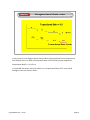
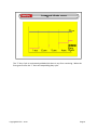
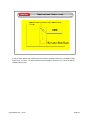
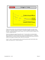
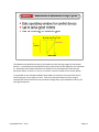
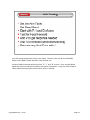
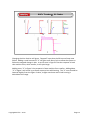
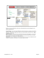
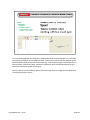
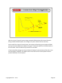
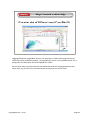
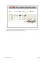
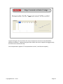
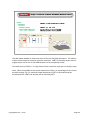
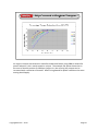
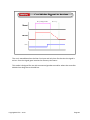
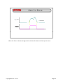
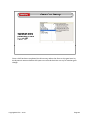
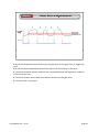
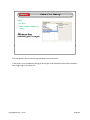
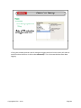
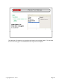
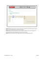
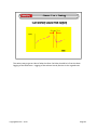
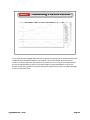
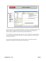
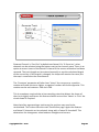
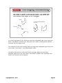
Copyright MoTeC – 2010
Page 1
Description of PID control will mainly be based around Duty Cycle control valves but the theory is still correct for stepper motors and DBW throttle bodies. Copyright MoTeC – 2010
Page 2
An open loop control system simply has a set operating state for various conditions, e.g. 50% at 5000rpm. If the system was for boost control 50% duty cycle at 5000rpm might produce a desired 1 bar of boost on the day of tuning. If 50% at 5000rpm is used on a day with cooler air temperature the boost might go to 1.1 bar. The error of 0.1 bar will not be taken into account and automatically used to change the duty cycle so that the desired 1 bar is achieved. Copyright MoTeC – 2010
Page 3
A closed loop control method is used when a set value is needed to be closely matched by an output. The closed loop system uses an Aim position set by the tuner and a feed back channel to monitor where the actual value is. How the output is controlled is based on the difference between the Aim and Actual positions, this is called the Error. The closed loop control system will vary the output to minimize the Error. Proportional, Integral and Derivative gains are tuned in a combination to give stable control of the output.
For the boost control example on the previous page this time the tuner would set 1 bar at 5000rpm. The duty cycle would still be roughly around 50% (if it is still the same physical system) but would be varied constantly to eliminate any potential errors.
A “Dead Band” can be set in the control setup. The Dead Band is a small range of error that is considered to be of any importance to the system, e.g. Idle Control Dead Band might be 50rpm above or below the Aim Idle. If the Dead Band is too small the PID control will work too hard and the system can be very sensitive and hard to tune.
Copyright MoTeC – 2010
Page 4
The Proportional Gain Produces a response that is directly proportional to the Error. If the output of a device was duty cycle, the response from an Error, if there is only Proportional Gain, would be: Duty = Proportional Gain x Error
Because the Proportional Gain Duty Cycle decreases as the Error decreases. There will be a point at which the error is small enough that any Proportional Duty Cycle it produces will not be enough to make any further difference and this small error will remain.
The amount of Proportional Gain is related to how quickly the system responds. If a small amount of “P” is used, the system will react slowly and is unlikely to remove a great deal of Error. A large amount of “P” is required if the system is to have fast response but too much can lead to over/undershooting of the Aim Position or “hunting”. Copyright MoTeC – 2010
Page 5
It can be seen in the diagram above that the Duty Cycle produced by the Proportional Gain follows the Error. With a Proportional Gain of 0.5 the Duty Cycle produced is:
Proportional Duty% = 0.5 x Error
It is possible that when the Error reaches 2, a Proportional Duty of 1% may not be enough to have any further effect.
Copyright MoTeC – 2010
Page 6
The Integral Gain (“I”) is used to remove any final Error when the “P” Duty gets too low to have any effect. While there is any error, the “I” Gain adds Duty Cycle proportional to the Error every second. As with “P” Gain, too much “I” Gain will result in instability and hunting. Copyright MoTeC – 2010
Page 7
The “I” Duty Cycle is continuously added while there is any Error remaining. When the Error goes to zero the “I” Gain will stop adding duty cycle.
Copyright MoTeC – 2010
Page 8
If Proportional Gain is thought of as an accelerator, the Derivative (“D”) Gain can be thought of as the brakes. When a large amount of “P” is used to give good system response, the “D” can be used to cure any slight over/undershoot hunting. Copyright MoTeC – 2010
Page 9
It can be seen above that while the Error remains constant there is no change in Duty Cycle from “D” Gain. As soon as there is any change in Error the “D” reacts to add or subtract Duty Cycle.
Copyright MoTeC – 2010
Page 10
All systems will have a Duty Cycle that will approximately produce the output needed. If the PID control system had a base Duty Cycle that would always be very close to what is needed, the PID control loop would have very little Error to correct and therefore be much easier to tune.
Some testing should be performed to determine the value that gives the smallest Error without any PID. Copyright MoTeC – 2010
Page 11
If there is some load on the controlled system that does not allow it to reach its aim value the “I” Duty will continue to increase. If the load is suddenly removed it is likely that the “I” duty will make the system’s position “flair” which can lead to instability. This is called “Integral Wind Up”. Positive and Negative Integral Clamp allow the “I” to only work in a narrow window above and below the Feed Forward Duty Cycle to avoid Integral Wind Up. The Positive Integral Clamp is an amount of Duty Cycle added to the Feed Forward (Normal Position) table and the Negative Integral Clamp is Duty Cycle subtracted.
If the “P” and “D” control is good any Error remaining will be small and therefore only need a small amount of “I” Duty to remove it. Copyright MoTeC – 2010
Page 12
The Maximum and Minimum Duty Cycle tables set the working range of the control device, i.e. the Maximum and Minimum Duty Cycle that the PID algorithm will calculate to. Generally these tables would be set based on the manufacturer’s data for the particular device so that it is not try to control a system outside of its normal ability.
It is possible to use the Max and Min Duty tables to clamp the control of the device which may give it less ability to hunt. Care must be taken because if the range is clamped too much the device may not have enough Duty Cycle available to do its job with good response. Copyright MoTeC – 2010
Page 13
Any PID tuning should start with an Aim value. The Aim value can be the Idle RPM, Boost Level, DBW Throttle Position, Cam Position, etc. Set Aim Table to desired value(s) and set “P”, “I” and “D” to zero. Set a sensible Dead Band with an Error that will not effect the system’s operation. Using the Feed Forward Table adjust the Duty Cycle until the Aim value is reached. Copyright MoTeC – 2010
Page 14
Changing the Aim Position will give a “Stepped” input that the PID control loop must follow. Adding a small amount of “P” will give some Duty Cycle to allow the system to follow the stepped change in Aim. It can be seen in figure 1 that the response is both slow and the Error, while smaller, is still quite large.
Adding more “P” in figure 2 the response is faster and the Error smaller. Adding More “P” in figure 3 will result in yet faster response but wild hunting. The “P” term should be lowered slightly from the figure 3 value, a slight overshoot and a little hunting is desirable at this stage.
Copyright MoTeC – 2010
Page 15
With an acceptable amount of overshoot and only a slight hunt, the response of the system at this stage should be quite fast. Adding some “D” in figure 4 will reduce the overshooting and reduce the amount of hunting. Care must be taken when adding “D” Gain as too much will lower the response as the error gets smaller, the “brakes” are put on too early. If the amount of “D” needed to reduce the overshoot and hunting to an acceptable level also causes a loss of response close to zero error, the “P” may need to be reduced for better overall system stability.
It should be noted that there is still a small Error in figure 4.
Copyright MoTeC – 2010
Page 16
Adding a small amount of “I” will remove any final error. In Figure 5 there is a small hunt followed by a small remaining error. The Error is removed by the “I” Duty Cycle.
Some more “I” may be added to reduce the remaining Error more quickly but as with the “P” gain adding too much will bring back hunting. Copyright MoTeC – 2010
Page 17
The Launch Control section of the Traction Control function simply monitors non‐driven wheel speed (Ground Speed) and uses a table to determine a lower RPM limit. The function should be made to stop just before the driver gets to the first gear change as an RPM limit is only relevant to one gear.
Copyright MoTeC – 2010
Page 18
Copyright MoTeC – 2010
Page 19
The Slip Calculation Mode is needed even if only the Launch Control section is to be used. If only the front wheel speeds are available, mode 1 should be used.
Copyright MoTeC – 2010
Page 20
There are two parts to the Launch Control RPM limiter: first is the cut where ignition events are randomly stopped, and the second is to reduce the ignition advance. Both the cut and the retard can be activated at different amounts of throttle position.
Copyright MoTeC – 2010
Page 21
Even though it is not directly used for the Launch part of the function, the Control Method still needs to be set. Anything other than 0 will work the same. Copyright MoTeC – 2010
Page 22
Similar to the main RPM limit, there are a few details that can be changed to suit different applications.
Control Range: Sets the range of RPM over which the limiter cut phases from 0% to 100% cut. The control range starts above the Launch RPM Limit table value. Bigger range gives softer cut.
RPM Limit Type: Allows the tuner to decide which part of the engine is cut to limit RPM. Ignition Cut is the most responsive but care must be taken that the exhaust system does not “load up” with unburned fuel.
Randomiser: Sets the pattern in which the cylinders are cut and can depend on the number of cylinders, trial and error is the best way to set this.
Copyright MoTeC – 2010
Page 23
It is recommended that the RPM Limit table be based on Ground Speed. It is a 3D table so another parameter can be added as well. The Launch Control will be stopped at the Ground Speed value at the end of the table, e.g. if the table axis goes to 45km/hr this is where Launch Control will stop. Maximum table axis value should correspond to just below the maximum speed in first gear.
Launch control is most effective when the wheel spin starts too high and the RPM limit is lowered just after launch.
Copyright MoTeC – 2010
Page 24
With the Launch Control function being related to RPM and the Slip Control function being related to Wheel Speed, the change over point needs to be set correctly. At the end of the Launch Control phase, the engine will be doing a set number of RPM (set by the Launch RPM Limit table) in first gear. The Drive Speed for this RPM needs to be calculated. Next the desired slip needs to be decided. If the Launch/Slip change over Ground Speed is 50Km/hr and the desired Slip (Set in the Aim Slip table) is 10Km/hr, the RPM at the end of the Launch Control phase needs to produce 60Km/hr of Drive Speed.
Copyright MoTeC – 2010
Page 25
The Ignition Retard table is used to reduce the timing advance during Launch Control. The Launch retard will stop at the same point the Launch RPM Limit table stops, i.e. Ground speed just before first gear change. Copyright MoTeC – 2010
Page 26
Slip Control takes over at the end of the Launch Control phase. Both Driven and Non‐
Driven (Ground) wheel speeds are compared to calculate Slip. A certain amount of slip is desirable to give maximum acceleration.
Copyright MoTeC – 2010
Page 27
The longitudinal force of a tyre is related to the slip, relative to the its speed along the ground. All tyres have a maximum amount of longitudinal force which will peak and begin to drop off until the wheel breaks into excessive spin. The idea of Traction Control is to keep the tyre speed at a high level of longitudinal force. Copyright MoTeC – 2010
Page 28
Slip Units: The calculated Slip in a direct speed measurement or in percentage of Ground Speed
Slip Filter: Filter for the calculated Slip
Driven Wheel Balance: A weighted average of the two Driven Wheel Speeds. Lower number gives more bias towards the slowest wheel.
TC Aim Slip Comp 1 and 2 Method: Is the compensation table base on a percentage change of Aim Slip or a direct addition of more Aim Slip
TC Aim Slip Filter: Filters the Aim Slip
Control Method: How is the engine’s power to be limited
P, I and D Gains: It is recommended that only P gain be used to start with
Copyright MoTeC – 2010
Page 29
It is possible to separately filter different parts of the Slip Control. The minimum values should always be used and these values should not be used to “band‐aid” other problems. Remember filtering a channel value will slow its response. Copyright MoTeC – 2010
Page 30
When the car is cornering, both driven wheels are turning at different speeds so can have different slip. The Driven Wheel Balance allows the tuner to have a Drive Speed channel calculated as a weighted average of both driven wheels. Copyright MoTeC – 2010
Page 31
The two Aim Slip Compensation tables can be set so that the number is either a percentage or straight additive.
Copyright MoTeC – 2010
Page 32
The gains for the Slip Control function. Best start with small values of P and use a Gain Compensation table and multi position switch to find an acceptable value of gain. The tuning of the PID can be very driver dependant so it is good to have a way that the drive can change the control on the fly. Copyright MoTeC – 2010
Page 33
The Aim Slip table sets how much difference is allowed between Drive Speed and Ground Speed. Copyright MoTeC – 2010
Page 34
Logging of Slip and Longitudinal G Force can be put on a scatter plot to get an idea of what slip is best at different speeds. If Longitudinal G Force is not available and i2 Pro is being used, the derivative of Ground Speed will suffice.
Be careful to note any points that do not follow the trend and investigate where they came from, e.g. the car hits an unusual bump at only one part of the track. Copyright MoTeC – 2010
Page 35
The Aim Slip table is 3D, giving good flexibility, but at times an extra axis or four could be needed. For example to have wet and dry settings.
Copyright MoTeC – 2010
Page 36
Compensating for Aim slip allows the tuner to adjust the amount of slip allowed for different conditions. Compensating the Gain allows the tuner to adjust how aggressively the ECU tries to control the Slip.
Gain compensation applies a % compensation to the P, I and D terms equally.
Copyright MoTeC – 2010
Page 37
The Max Power Reduction table sets the limit for the Slip (PID) calculation. This table is used to avoid excessive amounts of power reduction 100% in the table means that all engine power can be cut or the DBW throttle can be completely closed.
This table must be filled in. A single value can be entered to start with to simplify setup.
Note: When using DBW as the control method this table is in percentage of the current throttle reading, e.g. if a maximum Power Reduction of 50% is calculated and the throttle position is 60% the throttle will be closed by 30%. Copyright MoTeC – 2010
Page 38
The Retard Power Reduction table sets how much ignition retard to use based on a calculated Power Reduction. This table is only used if the Control Method is set to “retard” or “Retard then Cut”.
It is recommended that the effects of reduced ignition advance be tested first, preferably on a dyno. Copyright MoTeC – 2010
Page 39
If the Control Method is “Retard then Cut” the function will calculate a desired Power Reduction. Using that calculated Power Reduction the Retard Power Reduction table will be used to work out how will be from retard. If the maximum value of the Retard tables axis is less than the calculated Power Reduction the difference will be made up from cut.
Example: Calculated Power Reduction is 80% and the Retard Power Reduction table axis ends at 60%, 20% cut will be introduced. So in reality, the engine in this case will be retarded by 6 degrees and have 20% cut. Copyright MoTeC – 2010
Page 40
An engine’s torque characteristics should be understood when using DBW or Retard for power reduction, this is easily tested on a dyno. The example file above shows that in the case of throttle position at 2500rpm (engine is a low revving V8), torque can be increased with a reduction of throttle. When using Retard for power reduction the same testing should apply. Copyright MoTeC – 2010
Page 41
Copyright MoTeC – 2010
Page 42
When the ECU is instructed by the driver to cut the ignition system to reduce power so that the driver does not need to lift the throttle or use the clutch. Is only really relevant to dog engagement gearboxes, synchromesh systems do not allow for fast gear shifts.
Copyright MoTeC – 2010
Page 43
The simplest method to give the ECU a Gear Cut input is with a switch in the gear knob. Care must be taken to ensure the spring tension can be changed so that it can be setup for the particular gearbox and driver feel. You do not want it triggering too early or late.
Copyright MoTeC – 2010
Page 44
A strain gauge will measure the force the driver is putting on the gear lever and the ECU reads this as an analogue signal. The tuner can easily change the switching point for the Gear Cut in software based on data logging. It is also a good way to see exactly how the driver is using the gear lever.
Copyright MoTeC – 2010
Page 45
On most motorsport sequential gearboxes there will be a provision for a rotary potentiometer to measure the position of the selector barrel. The position sensor can be used to stop the cut when the gearbox is in the correct position, rather than relying on a best guess of how long the driver will take to change gears.
Calculated gear position uses the ratio of Engine RPM to gearbox output RPM to match to the closest known ratio in the ECU. The downside of a calculated gear is that if the Gear Cut is waiting for the next gear to be calculated before it can finish the cut there
Gear Cut is waiting for the next gear to be calculated before it can finish the cut there will be a noticeable delay in power recovery. Copyright MoTeC – 2010
Page 46
The cut mode offers three different methods of timing the amount of Gear Cut. These modes are basically indications for the ECU on when to both start and stop the cut.
Copyright MoTeC – 2010
Page 47
For Delay From Next Gear Stable the driver input is used to start the cut. The cut will continue until the ECU has detected that the gearbox has reached the next gear position without regard for what the driver is doing.
Once the next gear position is reached, there is a tuner‐defined delay time to make sure the gear is stable. This time is generally very small if anything at all.
After the delay time the power recover starts.
This mode is basically a closed loop system and can be used to help with inconsistent drivers’ gear changes.
Copyright MoTeC – 2010
Page 48
Delay From Cut signal uses the driver input to start the cut. The tuner‐defined delay time is used to decide how long the cut lasts without regard for the driver’s input or the actual gear position.
Once the delay has elapsed the recovery time will start.
This mode is an open loop system and is generally only used when there is no good way p
p y
g
y y
g
y
of measuring gear position.
Copyright MoTeC – 2010
Page 49
The cut is started based on the Gear Cut input and only lasts for the time the signal is active. Once the signal goes inactive the recovery time starts.
This mode is designed for use with an external gearbox controller where the controller decides how long the cut should last. Copyright MoTeC – 2010
Page 50
Apart from the normal switch or strain gauge on the gear lever, the ECU offers a few options for initiating the Gear Cut.
•Clutch Input: Use a digital input that is connected to the clutch pedal. This mean you still use the clutch but the driver does not lift. Only really used when the rules dictate that there is no specific gear change input from the lever.
•Change when RPM Limit Hit: Uses the RPM Limit status as the input. When the RPM Limit is hit this will start the cut.
•Throttle Position Reduction: Uses a throttle reduction rate of change to indicate an input. •Gear Shift Function: When there is full gearbox control and the up shift paddle is used to indicate a change for the gearbox control and the Gear Cut at the same time. Copyright MoTeC – 2010
Page 51
Like most functions in MoTeC ECUs, there are logical limits as to when the function needs to be on or off. For example, you probably don’t want the Gear Cut working while driving around the pits.
Drive education is essential so that they understand that if they are below these limits the function will not work.
Copyright MoTeC – 2010
Page 52
1: The driver begins to put force on the gear lever and this can also be seen in the voltage trace for the gear selector barrel (sequential gearbox). The selector barrel will rotate until all the mechanical tolerances are taken up. The force levels for the Gear Cut should be set high enough so that the driver is ready for the change, too early and the drive will not have enough force on the lever to accelerate it quickly enough.
2: The selector barrel starts to move rapidly between gears. The driver’s force on the lever will reduce because there is nothing to stop the barrel rotating.
3: The selector barrel reaches the next gear and the barrel stops rotating so the driver
3:
The selector barrel reaches the next gear and the barrel stops rotating so the driver’ss force will increase as the limits of the lever movement are reached, then the gear lever is released.
Copyright MoTeC – 2010
Page 53
The Gear Cut Forces set the level at which the function is triggered.
Copyright MoTeC – 2010
Page 54
When the force is above the High Level or below the Low Level the input is active.
Copyright MoTeC – 2010
Page 55
Once a shift has been completed, the drive must reduce the force on the gear lever by the Hysteresis amount before the input turns off and the driver can try for another gear change.
Copyright MoTeC – 2010
Page 56
1: Driver has requested a shift and has put enough force on the gear lever to trigger the input.
2: A shift has been completed but the driver leaves too much force on the lever 3: The driver requests another shift but this is ignored because the Hysteresis condition of force was not met
4: The driver realises the mistake and reduces the force on the gear lever
5: The next shift is successful Copyright MoTeC – 2010
Page 57
The Arm Delay is the minimum time between successive shifts. If the driver is not completely letting go of the gear lever between shifts there could be a false triggering on the Gear Cut.
Copyright MoTeC – 2010
Page 58
If using the throttle position rate of change to trigger the Gear Cut the tuner will need to work out what the driver is able to do consistently. This is best worked out from data logging.
Copyright MoTeC – 2010
Page 59
The Next Gear Terminate is only used for the Delay From Cut Signal mode. This will stop the cut if the next gear is reached before the delay time has elapsed. Copyright MoTeC – 2010
Page 60
Mode 1: Delay time once the next gear has been reached, e.g. for second gear it is the delay once the gearbox has moved to second gear.
Mode 2: Delay time started when a gear change is initiated, e.g. for second gear it is how long to delay when changing from second to third gear.
Mode 3: This is not used as the mode relies on the input being active only.
Copyright MoTeC – 2010
Page 61
The easiest way to get an idea of what the Gear Cut Delay should be is from the data logging of the RPM trace. Logging of the selector barrel position is also a good start. Copyright MoTeC – 2010
Page 62
The Recovery time allows the engine power to be slowly phased back into the engine to reduce the shock load on the drive train and to not shock the tyres either.
Too much recovery time will cause complaints from the driver as even a small amount too much will feel like seconds.
It is possible to lower the delay time in some instances so that the recovery time starts p
y
y
early before the next gear has been reached. Care must be taken when doing this if the driver has inconsistent shift times.
Copyright MoTeC – 2010
Page 63
When using Delay From Next Gear Stable mode it is possible for the driver to have a problem during the shift. Because the mode is supposed to finish the cut based on reaching the next gear, a missed shift will result in excessive cut times. The Timeout sets a maximum time a Gear Cut sequence can run for. It is important to remember that once the Timeout has been reached, the ECU will reinstate engine power regardless of where the gearbox is.
Copyright MoTeC – 2010
Page 64
The Gear Cut can be by way of simply cutting the spark events to a cylinder, reducing the amount of ignition timing or a combination of both.
The level of power reduction should be enough to reduce the engine load on the gear drive dogs and drop the RPM down enough for clean engagement with the next higher gear.
Cut is the most instantaneous method while retard can offer more control over the exact amount the power is reduced. Cut is the recommended and easiest way to get good results.
Copyright MoTeC – 2010
Page 65
Copyright MoTeC – 2010
Page 66
Copyright MoTeC – 2010
Page 67
There are two different ways to do lap timing. Using the standard infrared system with the BR2/BTX, which works with all MoTeC Dash Loggers, or using a GPS receiver, which also works with all MoTeC Dash Loggers (except for the first generation of ADLs).
The MoTeC Lap Beacon system consists of a Beacon Transmitter (BTX) and a Beacon Receiver (BR2). The Beacon Transmitter is mounted beside the track and the Beacon Receiver is mounted in the vehicle and connected to the Data Logging System or the Engine Management System The Lap Beacon system is used to mark the start of the lap
Engine Management System. The Lap Beacon system is used to mark the start of the lap. This can be used by a display system to show the driver lap times and lap number and can be used by a data logging system for lap time and start of lap information. The Lap Beacon may also be used to generate split times by placing multiple transmitters around the race circuit.
g
p
,
g
In order to get lap times, there must be a transmitting beacon on the side of the track. The car has a receiver which sees the infrared (invisible) light pulses. It then can display the lap time to the driver. It’s important for the data that the beacon transmitter be at the same spot on the track every time!
Copyright MoTeC – 2010
Page 68
Operation
The Beacon Transmitter emits a narrow infrared beam, which is encoded with a number that will only be detected by a receiver system with the same number. There must be no obstacles between the receiver and the transmitter.
Code Number
The MoTeC Lap Beacon has 1000 different code numbers. This number allows the beacon to ignore all transmitters, other than one with the correct code number. Range
The MoTeC Lap Beacon has a range of up to 40m (140 ft). Note: do not place the receiver behind window glass as this can reduce the range substantially. Polycarbonate (Lexan/Perspex) is acceptable.
Alignment
Both the transmitter and receiver must be aligned to within 5° of optimum (preferably 2°).
Receiver
The BR2 Beacon Receiver has two different connection methods: CAN Bus or Switched Output. The setup requirements of the receiver are different depending on which connection method is used.
Note: DO NOT remove the cover of the BR2, there are no switches inside.
As the beacon may be located on different sides of the car depending on track direction, check whether you need to swap the beacon from side to side as part of your pre race check before each race meeting.
Copyright MoTeC – 2010
Page 69
Transmitter
The code number is selected by setting the mode and ID (tens and units) switches inside the transmitter to the desired number as mentioned above. To access the switches, first disconnect the power then undo four screws and remove the front cover of the unit. You then access the switches. You can choose your mode and ID by rotating these switches with a screwdriver.
Spacing between Transmitters
The spacing between adjacent transmitters must be at least 6m (20ft) to avoid the (
)
signals from each transmitter conflicting with each other. This also includes other manufacturers’ beacons that emit an infrared beam.
Mounting
The beacon transmitter has 4 holes outside the sealing ring of the case; these holes may be used to mount the unit to a backing plate. Note that the backing plate should include a hole so that the LED is visible Any mounting system must ensure that the case
a hole so that the LED is visible. Any mounting system must ensure that the case remains watertight.
Power
The unit should be powered from a 12 V rechargeable battery. A small sealed lead acid battery is recommended as it can be easily charged and will operate the transmitter for several days. A capacity of 10AH or greater is recommended . Copyright MoTeC – 2010
Page 70
The easiest method to configure and the most popular is connecting the BR2 to your dash via CAN. Open Dash Manager, Select Lap Time and Number and then set the Beacon Type to BR2 (on CAN) and then set the Beacon number so that it matches your transmitter. Then use the BR2 CAN template, under Inputs‐>Communications and ensure that the following channels are being received as shown here, make sure you log them as they are good for troubleshooting.
CAN (Control Area Network) Bus connection method
This is the recommended method for use with the MoTeC Advanced Dash Logger (ADL). When the Receiver detects any Beacon Transmitter it sends the transmitter number to the connected device via the CAN Bus. The connected device (e.g. ADL) must be configured to use the same Mode and ID as the transmitter. All other beacon transmitters will be ignored. S it h d O t t C
Switched Output Connection Method
ti M th d
This method is used for older MoTeC devices that do not support the CAN Bus connection method (e.g. Older MoTeC ECUs). The BR2 is configured to recognise only a particular beacon. This is done using the BR2 Configuration program (there are no switches inside the BR2). When the BR2 detects a transmitter with a matching mode an ID a signal is sent to the connected device via the switched output. Copyright MoTeC – 2010
Page 71
Copyright MoTeC – 2010
Page 72
Copyright MoTeC – 2010
Page 73
Copyright MoTeC – 2010
Page 74
To setup GPS beacons you need a GPS receiver that transmits data via RS232 (NMEA messages RMC and GGA) at a minimum of 5 Hz.
RMC d GGA) t
i i
f5H
GPS receivers are becoming more popular in racing due to their ability to capture the global position of your vehicle as Latitude, Longitude and Altitude. Logging this data provides the line
driven around a race track, making it easy to overlay the driven lines from lap to lap and compare lines through a corner to, for example, entry and exit speeds.
To add to this further, the inside and outside edges of a track can be plotted by logging the GPS data while driving these lines. This data can be used later to show an actual track outline, overlaying the race lines then shows where on the track the vehicle is in relation to the edge and if the driver is using all of the available space to maximise corner speed.
Another use for GPS in motorsport is to create beacon points based on Latitude and Longitude for lap timing. The logging device is configured with one or more sets of coordinates and when the vehicle passes that point a beacon is triggered.
Vehicle speed must be above 20kmh to trigger a GPS beacon.
Copyright MoTeC – 2010
Page 75
The GPS unit has an integrated antenna and should be mounted on an external horizontal surface that has a clear view of the sky.
The unit should be mounted away from sources of interference including other antennas.
If mounting on a non metallic surface, it may be necessary to add a metallic ground g
y
y
g
plane under the unit to improve the signal level. The ground plane should be at least 150mm (6in) square and may be made of aluminium or steel.
The unit has a magnetic mounting base and includes an M3 thread in the centre.
Copyright MoTeC – 2010
Page 76
Edit Details Method:
1 O h Fil
1. On the File menu, click Edit Details
li k Edi D il
2. Click the Venue tab and then click Select
3. Choose the race track that you are going to and click Open. If the track does not exist in the list, click Cancel.
4. In the Details Editor, click New, enter a Venue Name and click OK.
It is good practice to fill in the other venue details, but this is not required for GPS Lap Beacons.
In the Venue Type box, ensure you select Loop or Cross Over if you are on a closed circuit.
5 If the numbers in the table are blank click Add to enter the correct Latitude and Longitude
5. If the numbers in the table are blank, click Add to enter the correct Latitude and Longitude coordinates for the beacon.
6. Once you have added the Latitude and Longitude Coordinates, click OK on the GPS Coordinates window, and then click OK on the GPS Coordinates Editor window to accept the
changes into the venue file.
Lap Time and Number Setup Method:
1. Select ‘Calculations – Lap Time and Number’ from the menu.
2. Select GPS as the beacon type and coordinate as the trigger.
3. Set the Detection Radius and Ignore time.
4. A number of points may be entered by pressing Add. Each venue includes Start and Stop point/s and optionally multiple split points.
5. Click OK and Send the configuration to the Dash.
Every time the vehicle comes within the detection radius of an entered point, a beacon is triggered as it passes the centre line, as long as the Beacon Ignore time has passed.
triggered
as it passes the centre line as long as the Beacon Ignore time has passed
Copyright MoTeC – 2010
Page 77
If you have previous logged data with a GPS, go to the relevant point and write down the Longitude and Latitude numbers at each point. The track map has been put on the screen so that the user can see where on the track the car is. The picture above shows the cursor positioned at a point on the track where a start/stop beacon is to be set. Simply record the numbers from the 2 positional channels and enter into Dash Manager as per the previous slide.
Copyright MoTeC – 2010
Page 78
Copyright MoTeC – 2010
Page 79
A track map provides a graphical representation of the venue at which the logged data was acquired. For this function to be available it is necessary for the following inputs to i d F thi f ti t b
il bl it i
f th f ll i i
t t
be logged: lateral G force, vehicle speed and a lap beacon. Or GPS data and a beacon. The software will then derive a map based upon the driving line of the fastest lap in the log file. The map allows the user to relate the data to the specific track position where an event has occurred.
In i2, track maps can be used to show a graphical representation of data logged in the log file. It can of course show the channels Throttle position, Brake Active and Gear, but log
file It can of course show the channels Throttle position Brake Active and Gear but
can also be used to show oil pressure across a lap, or braking pressures for instance, as shown in the rainbow track map examples above.
Select the workbook “User”, then add a new worksheet by right clicking on the worksheet name area
Call this sheet “Rainbow Track Map”, then right click on the page, then select “Add”, “rainbow track map”
Click on the button to the right of the “Colour Channel” box, and choose “G force long”
Click on the number of bands, and change it to 5, click the “reverse” button, then finish with “OK”
Copyright MoTeC – 2010
Page 80
The Track Editor is used to generate/regenerate a track map, create/modify sections and add new section categories. These can then be used to generate a time report or channel report, e.g. divide the track into 3 sectors for a time report.
The Track Editor can be accessed from the menu ‘Tools – Track Editor’, by right‐clicking on a track report and selecting ‘track editor’, or by right‐clicking on any track map and selecting ‘track editor’.
A track map will automatically be generated from data from the fastest lap that is selected on a venue for which no track map currently exists. Copyright MoTeC – 2010
Page 81
Distance Channel is ‘Corr Dist’ by default and lateral G is ‘G Force Lat’; other channels can be selected using the button next to the channel name. There is an option to use an invert of the lateral G channel if the sensor calibration had been reversed. The track length can be entered manually or use the calculated length of the current lap. If the length is changed, the shape will remain the same, but the map is rescaled to the new distance.
The ‘Curvature’ parameter will alter how “sharp” the corners are, a positive number will make the turns tighter, a negative number will do the opposite. This number can be set between –100 and +100.
This is sometimes required due to low sampling rates that distort the shape of the circuit slightly and hence this feature enables us to either ‘fatten’
the circuit slightly and hence this feature enables us to either fatten or or ‘thin’
thin the the
circuit down as required
Note that after regenerating a track map, the sections may need to be recalculated. This is done from the main Track Editor page. Again the distance and lateral G channels can be selected, along with a ‘lateral G threshold’. This determines the changeover value between straights and corners
determines the changeover value between straights and corners.
Copyright MoTeC – 2010
Page 82
It is not the right type of track: When the track map is displayed, right click on the track. Select “Track Editor” and then click “Generate Track” button, choose between Closed, Crossover Circuit or Open Circuit.
The orientation of the track is wrong: When the track map is displayed, right click on the track. Select “Track Editor”. Use “Rotate Model” slider.
The radius of the turns are either too small or too large: When the track map is displayed, right click on the track. Select “Track Editor” and then click “Generate Track” button, the curvature can be adjusted.
Copyright MoTeC – 2010
Page 83
Open the logging and display the Lateral G, Longitudinal G (if fitted) and Wheel Speed. If either of these will not display then they are probably not being logged and the map will not be drawn, check your Dash Manager setup and your sensor wiring
Copyright MoTeC – 2010
Page 84
The CAN (Controller Area Network) Bus consists of many devices all connected by the CAN Hi and CAN Lo wires. All devices on the CAN Bus exchange data. The CAN Bus allows a huge amount of flexibility when any device can use information from all other devices, e.g. engine control channels can be calculated in the Dash Logger from information coming from the expansion devices.
The wiring must consist of a main CAN Trunk with each end terminated with a 100 ohm resistor All branches must be less than 500mm The wires are twisted around each
resistor. All branches must be less than 500mm. The wires are twisted around each other and not twisted with any other wires. Copyright MoTeC – 2010
Page 85
Copyright MoTeC – 2010
Page 86