1
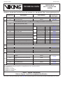
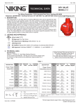
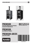
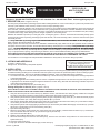
Firecycle 427a
January 12, 2007
TECHNICAL DATA
firecycle® III
multi-cycle deluge
system
The Viking Corporation, 210 N Industrial Park Road, Hastings MI 49058
Telephone: 269-945-9501 Technical Services 877-384-5464 Fax: 269-945-4495 Email: [email protected]
1. DESCRIPTION (Refer to Figures 1 and 2)
The Viking Firecycle® III Multi-Cycle Deluge System utilizes a Viking Model H or J Flow Control Valve (A.1) and a Firecycle® III Control
Panel (E.3) with additional valves, devices, and trim to form a unique operating system.
In addition to automatically detecting a fire and turning the system on, Firecycle® III has the added abilities to sense when the fire has
been controlled, and automatically turn off the water flow once a preprogrammed “Soak Timer” has been satisfied. If the fire rekindles,
Firecycle® III will initiate the sequence again. This unique cycling feature will repeat as long as power is available to the panel, helping
to minimize water usage, water damage, and the danger of pollution to surrounding areas.
Batteries are available to provide up to ninety (90) hours of emergency power. If the A.C. Power fails and the battery backup power
expires while the system is operating, the deluge system will “fail-safe”, and continue flowing until A.C. Power is restored or the system
is manually shut-off.
The ���������������
Firecycle® III ������������
Multi-Cycle �������������������������������������������������������������������������������������������������������
Deluge System������������������������������������������������������������������������������������������
has several fail-safe features, some of which are not available on other deluge systems.
Refer to Section B “System Operation” for details.
Deluge systems are commonly used where it is desirable to simultaneously spray water from all open sprinklers and/or nozzles on
the system when the system operates. Consult all Authorities Having Jurisdiction prior to installing a ����������������������������������
Firecycle® III Multi-Cycle Deluge
System����������������������������������������������������������������������������������������������������������������������������������
. The ����������������������������������������������������������������������������������������������������������������������������
Firecycle® III Multi-Cycle Deluge System������������������������������������������������������������������������������������
requires use of a Viking Flow Control Valve and trim kit with two electric Release
Solenoid Valves (E.1 and E.2) controlled by the Firecycle® III Control Panel (E.3), Firecycle® Detectors (E.4), and Detector Cable
(E.5). For proper location, spacing, and positioning of detectors, refer to Technical Data describing Viking Firecycle® Detectors.
NOTE: Firecycle® III is a complete system, and is listed as a unit. As such, it is normally not possible to modify
the components of the system controls or their inter-relation without compromising the listing.
For information on current approvals and permissible modifications to Firecycle® III, contact The Viking Corporation.
2. Listings and Approvals
UL Listed - Category VLLA
FM Approved - On-Off Multi-Cycle Sprinkler Systems
4. INSTALLATION
Viking Technical Data may be found on
The Viking Corporation’s Web site at
http://www.vikinggroupinc.com.
The Web site may include a more recent
edition of this Technical Data Page.
Refer to current Viking Technical Data describing individual components of the Viking Firecycle® III Multi-Cycle Deluge System. Technical Data describing the Viking Flow Control Valve and other system components are packed with product and in the Viking Engineering and Design Data book. Also refer to applicable installation standards, codes, and Authorities Having Jurisdiction.
1. The Flow Control Valve (A.1) and Trim must be installed only in areas where they will not be subjected to freezing temperatures
or mechanical damage.
2. All indicating appliances and releasing devices must be compatible and approved for use with the Firecycle® III System. Refer
to appropriate Fire Protection Equipment Approval Guides and current Viking Technical Data describing individual components
of the Viking Firecycle® III System.
3. Use only Firecycle® Detectors (E.4) and Cable (E.5).
Placing the System In Service (Refer to Figures 1 and 2)
Note: Refer to Firecycle® III Owner’s Manual and instructions provided in Technical Data describing the
Viking Flow Control Valve and other system components.
1. Verify that the Firecycle® III Control Panel (E.3), Detector Circuits, and Detectors have been properly installed and energized
according to instructions provided in Viking Technical Data and the Firecycle® III Owner’s Manual.
2. Verify that the system has been properly drained. (When plunger is depressed on drip check, (B.7) no water should flow.) System
Drain (D.3) should be open. Verify that Emergency Release (B.11) is closed.
3. Verify that the System Main Water Supply Control Valve (D.1) is closed and the Flow Control Valve (A.1) is trimmed according to
current Viking Trim Charts and schematic drawings for the system used.
4. Verify that the system water supply piping is pressurized up to the closed System Main Water Supply Control Valve (D.1) and the
priming line is pressurized up to the closed Priming Valve (B.1).
5. Open the Priming Valve (B.1).
6. Reset the Firecycle® III Control Panel (E.3) (Open panel and press “RESET”.) Release Solenoid Valve #1 (E.1) should close.
Flow from Release Solenoid Valve #1 (E.1) to Drain Cup (B.14) should stop.
7. Open the Flow Test Valve (B.15).
8. Partially open the Main Water Supply Control Valve (D.1).
9. When full flow develops from the Flow Test Valve (B.15), close the Flow Test Valve. Verify that there is no flow from the open
System Drain (D.3).
10. Close the System Drain (D.3).
11. Fully open and secure the Main Water Supply Control Valve (D.1)
Form No. F_081596
Revised page replaces page 427 a-d dated March 16, 2004
(Revised Format, added “Multi-Cycle”)
Firecycle 427b
January 12, 2007
TECHNICAL DATA
firecycle® III
multi-cycle deluge
system
The Viking Corporation, 210 N Industrial Park Road, Hastings MI 49058
Telephone: 269-945-9501 Technical Services 877-384-5464 Fax: 269-945-4495 Email: [email protected]
12. Verify that the Alarm Shut-off Valve (B.9) is open and that all other valves are in their normal operating position.
5. OPERATION (Refer to Figures 1 and 2)
In the SET condition:
System water supply pressure enters the priming chamber of the Flow Control Valve (A.1) through the 1/4” (8 mm) priming line, which
includes a normally open priming valve (B.1), strainer (B.2), restricted orifice (B.3) and check valve (B.4). In the SET condition, water supply pressure is trapped in the priming chamber by check valve (B.4), normally closed Release Solenoid Valve #1 (E.1), and
normally closed Pressure Operated Relief Valve (P.O.R.V.) (B.10), and the normally closed Emergency Release (B.11). Water supply
pressure in the priming holds the Flow Control Valve (A.1) clapper on the seat due to the differential design of the valve and spring
pressure. The clapper separates the inlet chamber from the outlet chamber, keeping the outlet chamber and system piping dry.
In fire conditions:
In fire conditions, when the Firecycle® III Detection System (E.4 and E.5) operates, the Firecycle® III Control Panel (E.3) activates a
piezo sounder and energizes normally closed Release Solenoid Valve #1 (E.1) open and normally open Release Solenoid Valve #2
(E.2) closed. Pressure is released from the priming chamber faster than it is supplied through the restricted orifice (B.3). The Flow
Control Valve (A.1) clapper opens to allow water to flow into the system piping and to alarm devices, causing Alarm Pressure Switch
(C.1) to activate. Water entering the system operates and hydraulically latches the P.O.R.V. (B.10) open. Water will flow from all sprinklers and/or spray nozzles attached to the system. Water discharges until all Firecycle® Detectors have reset, (cooled below their set
point). After all detectors have reset, the Firecycle® III Control Panel (E.3) activates the “Soak Timer”, allowing the system to continue
discharging water for a preset time period. When the “Soak Timer” has expired, the Firecycle® III Control Panel (E.3) de-energizes
normally closed Release Solenoid Valve #1 (E.1), allowing it to close. (The normally open Release Solenoid Valve #2 (E.2) remains
energized closed until the Firecycle® III Control Panel is manually reset, or both A.C. Power and battery backup have failed.) The Flow
Control Valve (A.1) re-primes and closes, stopping the flow of water through the system piping.
If a Firecycle® Detector goes into alarm, the Firecycle® III Control Panel (E.3) re-energizes normally closed Release Solenoid Valve
#1 (E.1) open, and the entire cycle repeats.
To return the system to “Normal” conditions, drain the system and relieve the pressure on the Pressure Operated Relief Valve (PORV)
(B.10) by draining the outlet chamber of the Flow Control Valve (A.1). Replace any Firecycle® Detectors that have been damaged,
and press the “System Reset” button on the Firecycle® III Control Panel (E.3) to clear all alarms.
Trouble conditions:
If the detection system is damaged or malfunctions, the Firecycle® III Control Panel will go into alarm and the Flow Control Valve will
open. Water will flow from all sprinklers and/or spray nozzles attached to the system. The cycling function of the Firecycle® III System
will not operate in this condition. All alarms will operate normally.
Loss of Power Prior to Operation:
If the AC power fails, the ���������������
Firecycle® III ������������
Multi-Cycle ���������������������������������������������������������������������������������
Deluge System��������������������������������������������������������������������
continues to operate on the standby batteries. If the AC power and
the standby batteries fail prior to the operation of the system, all alarms would be lost, and the system must be manually activated.
The cycling function of the system will not operate in this condition, and the system must be manually shut-off. Refer to Section D
“Emergency Instructions” for further information.
Loss of Power During Operation:
If all power fails while the system is flowing water, the normally open Release Solenoid #2 will fail open. The P.O.R.V. (B.10) is already
pressurized open, continually venting the priming chamber of the Flow Control Valve (A.1). The cycling function of the system will not
operate in this condition, and the system must be manually shut-off. Refer to Section D “Emergency Instructions” for further information.
Manual Operation:
Any time the handle inside Emergency Release (B.11) is pulled, pressure is released from the priming chamber faster than it can be
replaced through the priming line; the Flow Control Valve (A.1) will open. Water will flow from all sprinklers and/or spray nozzles attached to the system. The cycling function of the system will not operate in this condition, and the system must be manually shut-off.
After operating the Emergency Release (B.11), do not close the Emergency Release until the system is ready to be reset.
Emergency Instructions - �����������������������������
Taking System Out of Service� (Refer to Figures 1 and 2)
WARNING: Placing a control valve or detection system out of service may eliminate the fire protection
capabilities of the system. Prior to proceeding, notify all Authorities Having Jurisdiction. Consideration
should be given to employment of a fire patrol in the affected areas.
After a fire, verify that the fire is OUT and that placing the system out of service has been authorized by the appropriate Authority Having Jurisdiction.
Sprinkler systems that have been subjected to a fire must be returned to service as soon as possible. The entire system must be in-
Firecycle 427c
January 12, 2007
TECHNICAL DATA
firecycle® III
multi-cycle deluge
system
The Viking Corporation, 210 N Industrial Park Road, Hastings MI 49058
Telephone: 269-945-9501 Technical Services 877-384-5464 Fax: 269-945-4495 Email: [email protected]
spected for damage and repaired or replaced as necessary.
1. If All System Components Are Operational:
a. Open System Drain (D.3).
b. Silence alarms (optional):
i. To silence electric alarms controlled by Firecycle® III Control Panel (E.3), open panel, and press “ALARM SILENCE”
ii. To silence electric alarms not controlled by Firecycle® III Control Panel (E.1), close Alarm Shut-Off Valve (B.9).
Note: Electric Alarms controlled by a pressure switch installed in the ½” (15 mm) NPT connection for a
Non-interruptible Alarm Pressure Switch cannot be shut off until the Flow Control Valve is reset or
taken out of service.
c. To return to service immediately (when no maintenance or repairs are required) :
i. Close the System Drain (D.3), if opened in step 1-A.
ii. Open the Firecycle® III Control Panel (E.3) and press “RESET”.
iii. Open the Alarm Shut-Off Valve (B.9) (if it was closed in step B-2 above).
iv. Verify that all valves are secured in their normal operating position. (Refer to Figures 1 or 2 on page 427 d.)
2. If it is necessary to remove the Firecycle® III Multi-Cycle Deluge System from service:
a. Close the Main Water Supply control Valve (D.1).
b. Close the Priming Valve (B.1) (optional). If necessary, open the System Drain (D.3) to drain system and/or Test Valve (B.15)
to drain the inlet chamber of the Flow Control Valve (A.1).
c. Disconnect all power sources to the Firecycle® III Panel prior to performing any maintenance or repairs to the detection system (E.4, E.5), the panel (E.3), solenoid valves (E.1, E.2), or any electrical component of the system.
3. Perform all maintenance procedures recommended in Firecycle® III Owner’s Manual and Technical Data Pages for the individual
components of the system that has operated.
a. Replace any piping, detectors (E.4), or sections of detection cable (E.5) that have been damaged.
Note: The complete system operation must be tested after servicing, changing programming, addition or
deletion of system components, or after any modification, repair, or adjustment to system hardware
or wiring. All components, circuits, system operation, or software functions known to be affected by a
change must be 100% tested.
b. Replace any sprinklers and/or spray nozzles that have been damaged or exposed to fire conditions.
4. 4. Restore AC power to Firecycle® III Control Panel (E.3). Ensure that standby batteries are charged or charging. Always connect and turn on AC power source prior to connecting the standby batteries. Connecting the standby batteries to the Firecycle®
III Control Panel (E.3) before the AC power is connected and turned on may damage the panel.
5. 5. Return the system to service. Refer to Section E: “PLACING THE SYSTEM IN SERVICE”.
6. Inspections, Tests and Maintenance
Inspections and Tests
It is imperative that the system be inspected and tested on a regular basis. Refer to INSPECTIONS and TESTS recommended in current Viking Technical Data describing individual components of the Viking ���������������
Firecycle® III ������������
Multi-Cycle Deluge
��������������
System�.
Where difficulty in performance is experienced, the manufacturer or their authorized representative shall be contacted if any field
adjustment is to be made.
The frequency of the inspections may vary due to contaminated or corrosive water supplies or corrosive atmospheres. For minimum
maintenance and inspection requirements, refer to NFPA 25. In addition, the Authority Having Jurisdiction may have additional maintenance, testing, and inspection requirements that must be followed.
WARNING: Any system maintenance that involves placing a control valve or detection system out of service
may eliminate the fire protection capabilities of that system. Prior to proceeding, notify all Authorities
Having Jurisdiction. Consideration should be given to employment of a fire patrol in the affected areas.
Maintenance
NOTICE: The owner is responsible for maintaining the fire protection system and devices in proper operating condition.
To perform maintenance on Detection cable or Detectors without taking the entire system out of service, disable input zone #1. Disabling Input zone #1 disables the detection cable and detectors, leaving the ability to operate the Deluge System manually by use of
the Emergency Release or any manual pull stations (if provided) connected to input circuit 2.
Note: When zone #1 is disabled, if it is necessary to activate the system using the Emergency Release or a manual pull station connected to input circuit #2, do not reset the Emergency Release or manual pull station used or the system may cycle off.
When input zone #1 is disabled, the Firecycle® III Detector Cable remains charged with a maximum short circuit current of 40mA of 24
Firecycle 427d
January 12, 2007
TECHNICAL DATA
firecycle® III
multi-cycle deluge
system
The Viking Corporation, 210 N Industrial Park Road, Hastings MI 49058
Telephone: 269-945-9501 Technical Services 877-384-5464 Fax: 269-945-4495 Email: [email protected]
VDC. When disabled, an open circuit condition on input circuit #1 will cause the trouble relay to activate and the system trouble LED
to activate, but will not activate any output circuit associated with input #1.
To disable input circuits and associated output circuits for maintenance, refer to Firecycle® III Owner’s Manual and applicable Firecycle® III wiring diagram to determine which output circuits are activated by each input circuit.
1. Open the Firecycle® III Control Panel. (E.3)
2. Press and hold TONE SILENCE button
3. While holding the TONE SILENCE button, press the following buttons in sequence: ALARM SILENCE, ALARM ACTIVATE, and
SYSTEM RESET.
a. The zone #1 LED will flash indicating Zone #1 is selected. To disable zone #1, continue holding the TONE SILENCE button
and press SYSTEM RESET once (again). The yellow LED will flash indicating zone #1 is disabled.
b. To disable subsequent zones, continue holding the TONE SILENCE button and press the ALARM SILENCE button to select
the next zone (the LED will flash on the zone selected) or ALARM ACTIVATE button to select the previous zone. Continue to
holding ALARM SILENCE and press SYSTEM RESET to disable a selected zone. When disabled, the yellow LED will flash
indicating the zone is disabled.
4. When desired zones are disabled, release the TONE SILENCE button. The Piezo sounder will sound.
5. To silence the Piezo, press TONE SILENCE.
6. To re-enable a disabled zone, repeat the procedure.
Note: If any zone has been disabled, the Trouble Relay will activate and the System Trouble LED will flash.
If a zone has been disabled, an alarm that occurs on that zone will flash the red zone LED, but will not
sound the Piezo or activate any output circuit. If both power sources are removed from the system, all
zones will be re-enabled upon restoration of power. Disable status is lost.
Refer also to MAINTENANCE INSTRUCTIONS provided in current Viking Technical Data describing individual components of the
Viking �����������������������������������������
Firecycle® III Multi-Cycle Deluge System�.
7. AVAILABILITY
The Viking Firecycle® III Multi-Cycle Deluge System is available through a network of domestic and international distributors. See the
Viking Corp. Web site for closest distributor or contact The Viking Corporation.
8. GUARANTEE
For details of warranty, refer to Viking’s current list price schedule or contact Viking directly.
Firecycle 427e
January 12, 2007
firecycle® III
multi-cycle deluge
system
TECHNICAL DATA
The Viking Corporation, 210 N Industrial Park Road, Hastings MI 49058
Telephone: 269-945-9501 Technical Services 877-384-5464 Fax: 269-945-4495 Email: [email protected]
Component
A
Description
Part Numbers
Corresponding
Data Pages
Various
500 - 508
System Valve
A.1
Flow Control Valve
Firecycle® III Trim
(Trim and Flow Control Valve is included with the Package Part Numbers shown below)
B
C
B.1
Priming Valve (Normally Open)
B.2
Strainer
B.3
1/8” Restricted Orifice
Firecycle® III Valve and Trim Packages
1-1/2”
B.4
Spring Loaded Check Valve
B.5
Alarm Test Valve (Normally Closed)
B.6
Drip Check Valve
B.7
Drain Check Valve
B.8
Alarm Shut-Off Valve (Normally Open)
B.9
Pressure Operated Relief Valve (PORV)
2”
B.10
Emergency Release
B.11
Priming Pressure Water Gauge and Valve
B.12
Water Supply Pressure Gauge and Valve
B.13
Drain Cup
B.14
Flow Test Valve (Normally Closed)
C.1
Water Flow Alarm Pressure Switch
3”
4”
6”
8”
Angle
10100
Straight Through
126911
442 a-b
442 e-f
Angle
10101
445 a-b
Straight Through
126942
442 e-f
Angle
10102
448 a-b
Straight Through
126183
445 e-f
Angle
10103
448 a-b
Straight Through
123483
448 e-f
Angle
10104
448 a-b
Straight Through
123513
448 e-f
Straight Through
121004
448 e-f
Water Flow Alarm Equipment
09470
705 a-b
-
-
Riser
D
D.1
Water Supply Control Valve
D.2
System Drain (Recomended)
Sized according to NFPA 13
Release System
E
E.1
Release Solenoid Valve # 1 (Normally
Closed)
Various
E.2
Release Solenoid Valve # 2 (Normally
Open)
11595
E.3
Firecycle® III Control Panel
Various
433 a-h
E.4
Firecycle® Detector
Various
417 a-d
E.5
Firecycle® Detector Cable
Various
419 d-f
274 a-b
Footnotes: Add inlet and outlet designation to base part number for straight through style valves.
(TT - Threaded, FF - Flange X Flange, FG - Flange X Groove, GG - Groove X Groove)
1 Available in TT only
2 Available in TT and GG
3 Available in FF, FG and GG
4 Available in FF and GG
Table 1 - System Components
Refer to Figures 1 and 2 for component Identification
Note: When viewing this Data Page online, blue text represents hyper links and will open the desired data page when clicked.
Firecycle 427f
January 12, 2007
TECHNICAL DATA
firecycle® III
multi-cycle deluge
system
The Viking Corporation, 210 N Industrial Park Road, Hastings MI 49058
Telephone: 269-945-9501 Technical Services 877-384-5464 Fax: 269-945-4495 Email: [email protected]
Figure 1 - Angle Style Valve
Form No. F_081596
Figure 2 - Straight Through Valve
Revised page replaces page 427 a-d dated March 16, 2004
(Revised Format, added “Multi-Cycle”)