1
About This Guide
This section discusses the objectives, audience, organization, and conventions of the
Cisco 4000 Series Installation Guide publication. Use this publication to install and
maintain the Cisco 4000-M, Cisco 4500-M, and the Cisco 4700-M.
Cisco documentation and additional literature are available on a CD-ROM called Cisco
Connection Documentation, Enterprise Series. The CD is updated and shipped monthly, so
it might be more current than printed documentation. To order the Cisco Connection
Documentation, Enterprise Series CD, contact your local sales representative or call
Customer Service. The CD is available both as a single CD and as an annual
subscription.You can also access Cisco technical documentation on the World Wide Web
URL http://www.cisco.com.
Documentation for older modules in the Cisco 4000 series can also be found on the Cisco
Documentation CD.
Document Objectives
This publication contains the initial site preparation, installation, troubleshooting, and
selected upgrade and maintenance procedures.
Audience
This publication is for the router installer, who should be familiar with electronic circuitry
and wiring practices and have experience as an electronic or electromechanical technician.
For software configuration information, refer to the appropriate software publication. (See
the section “If You Need More Information“ in the chapter “Configuring Cisco 4000 Series
Software.”)
About This Guide xxiii
Document Organization
Document Organization
The major sections of this user guide are as follows:
•
Chapter 1, “Overview of the Cisco 4000 Series Routers,” contains an overview of the
Cisco 4000 series features and physical specifications.
•
Chapter 2, “Preparing to Install Cisco 4000 Series Routers,” includes safety
recommendations, site requirements, the Installation Checklist and Site Log, tools and
equipment, and instructions for inspecting the new system.
•
Chapter 3, “Configuring the Cisco 4000 Series Chassis,” describes how to access the
internal components of the router, replace network processor modules, and install the
component tray.
•
Chapter 4, “Making External Connections to Cisco 4000 Series Routers,” describes slot
numbering and unit numbering, console and auxiliary port connections, and each kind
of network connection: Ethernet, Token Ring, serial, G.703/G.704, Fiber Distributed
Data Interface (FDDI), Basic Rate Interface (BRI), channelized T1/Integrated Services
Digital Network (ISDN) Primary Rate Interface (PRI), channelized E1/ISDN PRI, and
Asynchronous Transfer Mode (ATM).
•
Chapter 5, “Configuring Cisco 4000 Series Software,” includes instructions for booting
the router for the first time, using the enable secret and enable password, configuring the
router, configuring interfaces, checking the router configuration, and saving the router
configuration.
•
Appendix A, “Troubleshooting the Initial Hardware Configuration,” discusses
recovering a lost enable password, troubleshooting, environmental reporting features,
and problem solving using the LEDs.
•
Appendix B, “Cabling Specifications for Cisco 4000 Series Routers,” provides cable
illustrations and pinouts for the console and auxiliary ports, and synchronous serial,
Ethernet, Token Ring, BRI, channelized T1 and channelized E1 cables.
•
Appendix C, “Replacing Memory in Cisco 4000 Series Routers,” provides instructions
for replacing single in-line memory modules (SIMMs) and boot ROM chips.
•
Appendix D, “Cisco 4000 Series Virtual Configuration Register,” describes the
Cisco 4000-M virtual configuration register and procedures for changing the
factory-default settings.
xxiv Cisco 4000 Series Installation Guide
Document Conventions
•
Appendix E, “Cisco 4000-M ROM Monitor,” describes the Cisco 4000-M ROM
monitor and to run the ROM monitor diagnostics.
•
Appendix F, “Cisco 4500-M and Cisco 4700-M ROM Monitor,” describes how to
enable the ROM monitor program and its commands and conventions.
•
Appendix G, “Translated Safety Warnings,” contains translations of the safety warnings
that appear in this user guide.
Document Conventions
This manual uses the following conventions to convey instructions and information:
Command descriptions use these conventions:
•
•
•
•
Commands and keywords are in boldface font.
Variables for which you supply values are in italic font.
Elements in square brackets ([ ]) are optional.
Alternative but required keywords are grouped in braces ({ }) and are separated by a
vertical bar ( | ).
Samples use these conventions:
•
•
•
•
Terminal sessions are printed in screen font.
Information you enter is in boldface
screen
font.
Nonprinting characters are shown in angle brackets (< >).
Information the system displays is in screen font, with default responses in square
brackets ([ ]).
Note Means reader take note. Notes contain helpful suggestions or references to materials
not contained in this manual.
About This Guide xxv
Document Conventions
Timesaver Means the described actions saves time. You can save time by performing the
action described in the paragraph.
Caution Means reader be careful. You are capable of doing something that might result
in equipment damage or loss of data.
Warning Means danger. You are in a situation that could cause bodily injury. Before you
work on any equipment, be aware of the hazards involved with electrical circuitry and
standard practices for preventing accidents. (To see translated versions of this warning,
refer to the appendix “Translated Safety Warnings.”)
xxvi Cisco 4000 Series Installation Guide
1
CHAPT E R
Overview of the Cisco 4000
Series Routers
The Cisco 4000 series consists of the Cisco 4000-M, the Cisco 4500-M, and the
Cisco 4700-M. All models provide a configurable modular router platform using network
processor modules—individual modules that when installed in the router are ready for
external network connections. Performance is the key distinction between the
Cisco 4000-M, Cisco 4500-M, and Cisco 4700-M.
For maximum performance in the Cisco 4000 series, the Cisco 4700-M contains a
133-MHz RISC microprocessor, 16 to 64 MB main memory, and a 512-KB secondary
cache. The faster speed of the Cisco 4700-M allows higher throughput for high-speed
interfaces. The 512-KB secondary cache is useful for process switching applications such
as compression and encryption.
The Cisco 4500-M contains a 100-MHz RISC microprocessor and 8 to 32 MB of main
memory. The Cisco 4000-M contains a 40-MHz CISC microprocessor and 4 to 32 MB of
main memory.
All Cisco 4000 series routers provide flexibility, allowing network managers to easily
reconfigure the router when needs change.
The Cisco 4000 series routers support up to three network processor modules at a time. The
following network processor modules are available at the publication date of this guide:
•
•
Single-port Fast Ethernet with 100BaseT and MII connectors provided for the port
•
•
Six-port Ethernet with 10BaseT connectors provided for each port
Single-port and dual-port Ethernet with 10BaseT and AUI connectors provided for each
port
Dual-port and four-port synchronous serial supporting EIA/TIA-232, EIA/TIA-449,
V.35, X.21, NRZ/NRZI, DTE/DCE, or EIA-530 DTE interfaces on each port
Overview of the Cisco 4000 Series Routers 1-13
•
Dual-port high-speed synchronous serial and 16-port low-speed
synchronous/asynchronous serial. The high-speed ports supports EIA/TIA-232,
EIA/TIA-449, V.35, X.21, NRZ/NRZI, DTE/DCE, or EIA-530 DTE interfaces. The
low-speed ports support EIA/TIA-232, V.35, or X.21 interfaces in DTE or DCE mode.
Each low-speed port can be individually configured for synchronous or asynchronous.
•
•
•
•
•
•
•
•
•
Single-port HSSI
Single-port and dual-port Token Ring
Dual attachment single-mode FDDI
Single attachment or dual attachment multimode FDDI
Four-port or eight-port ISDN BRI
Four-port balanced or unbalanced G.703/G.704
Single-port channelized T1/ISDN PRI
Single-port balanced or unbalanced channelized E1/ISDN PRI
Single-port ATM with single-mode OC-3 and long-reach capability, multimode OC-3,
DS-3, or E3 interfaces
Note For information about modules released after publication of this guide, see the
configuration note packet shipped with your router.
Note EIA/TIA-232 and EIA-TIA-449 were known as recommended standards RS-232
and RS-449 before their acceptance as standards by the Electronics Industries Association
(EIA) and Telecommunications Industry Association (TIA)
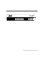
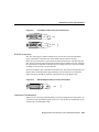
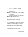
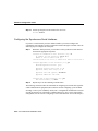
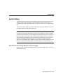
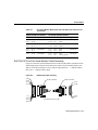
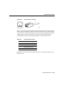
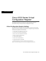
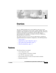
Figure 1-1 shows the front panel of a Cisco 4000 series router.
Figure 1-1
Cisco 4000 Series Chassis—Front Panel
1-14 Cisco 4000 Series Installation Guide
1
2
3
DATA
DATA
DATA
OK
OK
OK
OK
POWER
H3590
SERIES
Overview of the Cisco 4000 Series Routers 1-15
Series Specifications
Series Specifications
Design specifications for the Cisco 4000 series are as follows:
•
•
•
Modular router platform.
•
•
•
•
Hardware thermal alarm to warn of excessively high operating temperature.
Flash memory capability.
User-upgradable network processor modules, shared memory, and processor local
memory.
Can be rack-mounted in either a standard 19-inch rack or a telco rack.
Can be mounted on a wall or placed on a desk or table.
Support for up to three network processor modules at a time. Network processor
modules can be placed in any of the three available positions in almost any desired
combination. See the Cisco Product Catalog for complete configuration details.
The BRI four-port and eight-port network interface modules can not be used in the same
chassis with the channelized T1/ISDN PRI network interface module or the channelized
E1/ISDN PRI network interface module.
The Cisco 4000-M does not support Fast Ethernet, HSSI, 2T16S, ATM, or six-port Ethernet
network processor modules.The Cisco 4000-M can support only one FDDI network
processor module in combination with any two other types of network processor modules.
The Cisco 4500-M and Cisco 4700-M can support two FDDI network processor modules.
If you are only using one FDDI module, install it in the center slot for optimum heat
dissipation.
The Cisco 4500-M and Cisco 4700-M can support one ATM network processor module or
up to three six-port Ethernet network processor modules. The single-port Ethernet module
is not supported on the Cisco 4500-M or the Cisco 4700-M.
Note The Cisco 4500-M and Cisco 4700-M support all network processor modules
except the single-port Ethernet network processor module.
1-16 Cisco 4000 Series Installation Guide
Series Specifications
For complete configuration information, refer to the Cisco Product Catalog, which is
available on the Web at http://www.cisco.com.
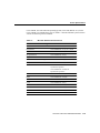
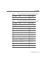
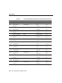
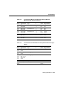
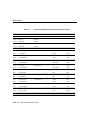
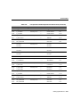
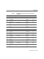
Table 1-1 lists the network processor module interface options available for the Cisco 4000
series when this guide was printed. For current modules, see the configuration note packet
that shipped with your router.
Interface Options
Port Options
Part Numbers
Ethernet
Single port, dual port, or six port
NP-1E=, NP-2E=, NP-6E=
Fast Ethernet
Single port
NP-1FE=
Synchronous serial
Dual port or four port
NP-2T=, NP-4T=
Synchronous/asynchronous
serial1
Dual high-speed ports and
16 low-speed ports
NP-2T16S=
HSSI
Single HSSI port
NP-1HSSI=
Token Ring
Dual port or single port
NP-1RV2=, NP-2R=
Multimode FDDI
Single attachment or dual attachment
NP-1F-D-MM=,
NP-1F-S-M=
Single-mode FDDI
Dual attachment
NP-1F-D-SS=
BRI
Four port or eight port
NP-4B=, NP-8B=
2
NP-4GB=, NP-4GU=
G.703
Four port (balanced or unbalanced)
Channelized T1/ISDN PRI
Single channelized T1/PRI port
NP-CT1=
Channelized E1/ISDN PRI
Single channelized E1/PRI port
NP-CE1=
ATM
Single ATM port
NP-1A-SM=,NP-1A-MM=
, NP-1A-DS3=,
NP-1A-E3=
1. Each low-speed port can be individually configured for synchronous or asynchronous.
2. For G.703 and G.704 connections, balanced or unbalanced ports must be matched with the corresponding
balanced or unbalanced cable.
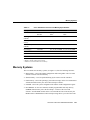
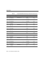
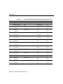
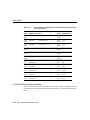
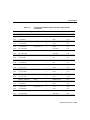
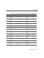
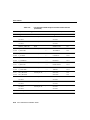
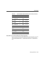
Table 1-1 lists the specifications of the Cisco 4000 series routers.
Overview of the Cisco 4000 Series Routers 1-17
Series Specifications
Table 1-1
System Specifications
Description
Specification
Dimensions (H x W x D)
3.4 x 17.6 x 17.7" (8.6 x 44.7 x 45 cm)
Weight
24 lb (10.9 kg) (including the chassis and network processor
modules)
Power
100–240 VAC, 50–60 Hz, 3.0–1.5A or 40–72 VDC, 5–2.8A
Wire gauge for DC-input
power connections
14 AWG1
Network interface options
Ethernet, serial, Token Ring, FDDI, BRI, G.703, channelized
T1/PRI, channelized E1/PRI, ATM
Serial interfaces
EIA/TIA-232, EIA/TIA-449, V.35, X.21, NRZ/NRZI, DTE/DCE,
EIA-530 DTE
Console port
EIA/TIA-232 DB-25 female connector
Auxiliary port
EIA/TIA-232 DB-25 male connector
Nonoperating temperature
– 40–185°F (– 40–85°C)
Operating humidity
5–95%, noncondensing
Operating temperature
32–104°F (0–40°C)
Regulatory compliance
FCC Class A, FCC Part 68, Canadian DOC Class A, CS-03, UL
1950 2nd edition, CAN/CSA 950-M93, EN60950 with
Amendments 1 and 2, AN/NZS 3260, NOM 019
Additional regulatory compliance is in the Cisco 4000 Series
Public Network Certification document that shipped with your
router.)
1. AWG = American Wire Gauge
Software Compatibility
Network processor modules must be supported by the appropriate level of system software.
The minimum system software version for the original Cisco 4000 was Software
Release 9.1; for the Cisco 4000-M, Software Release 9.14; for the Cisco 4500, and
1-18 Cisco 4000 Series Installation Guide
Series Specifications
Cisco 4500-M, Cisco Internetwork Operating System (Cisco IOS) Release 10.2; for the
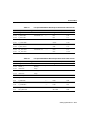
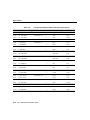
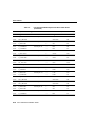
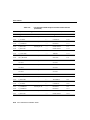
Cisco 4700-M, Cisco IOS Release 10.3(10). Table 1-2 lists the minimum system software
versions for network processor modules.
Table 1-2
Minimum Software Release Version
Network Processor Module Type
Minimum Software Release Version
Multimode FDDI
Software Release 9.14(1)
Fast Ethernet
Cisco IOS Release 11.1(5) or 11.2(2)P
Dual Ethernet
Software Release 9.14(2)
Six-port Ethernet
Cisco IOS Release 10.3(6)
Single-mode FDDI
Software Release 9.14(3)
Dual and Version 2 Token Ring
Software Release 9.14(5)
Four-port serial
Software Release 9.14(6)
2T16S-RS232 and 2T16S-V.35
Cisco IOS Release 11.2(3)P for
synchronous operation
Cisco IOS Release 11.2(4)P for
asynchronous operation
2T16S-X.21
Cisco IOS Release 11.2(5)P
HSSI
Cisco IOS Release 11.2(5)P
ISDN BRI
Cisco IOS Release 10.2
G.703
Cisco IOS Release 10.2(7)
Channelized T1/ISDN PRI
Cisco IOS Release 10.3(4)
Channelized E1/ISDN PRI
Cisco IOS Release 10.3(4)
ATM OC-3C
Cisco IOS Release 10.3(4)
ATM DS-3 and E3
Cisco IOS Release 11.0(5)
Overview of the Cisco 4000 Series Routers 1-19
Series Specifications
Note The Cisco 4000 can no longer be ordered, but Cisco IOS Releases 10.0, 10.2, and
10.3 are supported on installed Cisco 4000 routers. The Cisco 4500 can no longer be
ordered, but Cisco IOS Releases 10.1, 10.2, and 10.3 are supported on installed Cisco 4500
routers. The Cisco 4700 can no longer be ordered, but Cisco IOS Release 10.3 is supported
on installed Cisco 4700 routers.
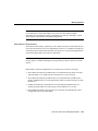
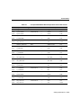
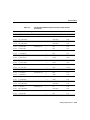
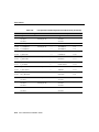
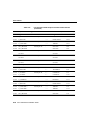
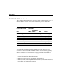
Table 1-3 lists the processor and memory specifications of the Cisco 4000 series routers.
1-20 Cisco 4000 Series Installation Guide
Memory Systems
Table 1-3
Cisco 4000 Series Processor and Memory Specifications
Description
Cisco 4000-M
Cisco 4500-M
Cisco 4700-M
Processor
40-MHz Motorola
68EC030
100-MHz IDT Orion
RISC1
133-MHz IDT Orion
RISC
Main memory
(DRAM)2
4, 8, 16, or 32 MB
8, 16, or 32 MB
16, 32, or 64 MB
Secondary cache
memory
None
None
512 KB
Shared memory
(DRAM)
4 or 16 MB
4, 8, or 16 MB
4, 8, or 16 MB
Flash memory
4 or 8 MB
4, 8, 16, 32, or 64 MB
4, 8, 16, 32, or 64 MB
128 KB
128 KB
128 KB
Boot ROM
128 KB–8 MB
128–512 KB
128–512 KB
Boot Flash
Not available
4–16 MB
4–16 MB
NVRAM
3
1. The Orion microprocessor is based on the MIPS R4400 and is pin-compatible.
2. DRAM = dynamic random-access memory.
3. NVRAM = nonvolatile random-access memory.
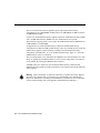
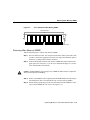
Memory Systems
The Cisco 4000 series memory systems (see Figure 1-2) have the following functions:
•
Main memory—Stores the running configuration and routing tables. The Cisco IOS
software executes from main memory.
•
•
Shared memory—Used for packet buffering by the router’s network interfaces.
•
•
NVRAM—Stores the system configuration file and the virtual configuration register.
Flash memory—Stores the operating system software image. In the Cisco 4500-M and
4700-M, the Flash memory also stores the boot helper software.
Boot EPROM—In the Cisco 4000-M, erasable programmable read-only memory
(EPROM)-based memory stores the boot helper—a subset of the Cisco IOS
software—and the ROM monitor. In the Cisco 4500-M and Cisco 4700-M, only the
ROM monitor is EPROM based. The boot helper image allows you to boot the router
Overview of the Cisco 4000 Series Routers 1-21
Memory Systems
when Flash memory does not contain a valid system image. In the Cisco 4500-M and
4700-M, the ROM monitor allows you to boot a system image from Flash memory if a
boot helper image is not present in boot Flash memory.
The differences between the memory systems in the Cisco 4000 series allows enhanced
software upgradability in the Cisco 4500-M and Cisco 4700-M.
Note See the appendixes “Cisco 4000 Series Virtual Configuration Register,”
“Cisco 4000-M ROM Monitor,” and “Cisco 4500-M and Cisco 4700-M ROM Monitor”
for more information on the ROM Monitor.
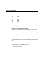
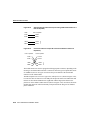
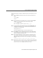
Figure 1-2
Cisco 4000 Series Memory Systems and Software Images
Cisco 4000 and Cisco 4000-M
EPROM-based
Boot helper
(xboot)
Flash-memory based
Cisco IOS
ROM monitor
Cisco 4500, Cisco 4500-M, Cisco 4700, and Cisco 4700-M
ROM monitor
1-22 Cisco 4000 Series Installation Guide
Flash-memory based
Boot helper
(xboot)
Cisco IOS
H3537
EPROM-based
Memory Systems
Memory Requirements in the Cisco 4000 Series
Each module in the Cisco 4000 series can change memory configurations to accommodate
internetworking demands. The memory requirements are affected by the following factors:
•
The number of Cisco IOS software images a system stores can be increase by adding
Flash memory.
•
Network expansion, the use of additional protocols or Cisco IOS services, or newer
Cisco IOS releases may require additional main memory
•
I/O performance or more physical or virtual interfaces may require additional shared
memory.
Shared Memory Requirements
The standard configuration for shared memory is 4 MB for the Cisco 4000 series. 4 MB of
memory is enough for most configurations with fewer than 24 physical or virtual interfaces.
Routers with multiple ISDN BRI network processor modules or with 24 or more physical
and virtual interfaces require 8 to 16 MB of shared memory.
Note The types and numbers of network processor modules installed in a system does not
affect main or flash memory requirements.
Overview of the Cisco 4000 Series Routers 1-23
Memory Systems
Table 1-4
Cisco 4000-M Shared Memory Requirements
Network Processor Module
Per-Module Shared Memory
Requirements
Single-port Ethernet
0.1 MB
Dual-port Ethernet and dual-port
serial
0.2 MB
Dual-port Token Ring, four-port
serial, and G.703/G.704 serial
0.4 MB
Eight-port BRI, CT1/PRI, and
CE1/PRI
1.0 MB
FDDI
2.0 MB
Table 1-5
Cisco 4500-M and Cisco 4700-M Shared Memory Requirements
Network Processor Module
Per-Module Shared
Memory Requirements
Dual-port Ethernet and dual-port serial
0.4 MB
Single-port Fast Ethernet
1.7 MB
Dual-port Token Ring, four-port serial, and G.703/G.704 serial 0.6 MB
Six-port Ethernet, Eight-port BRI, CT1/PRI, and CE1/PRI
ATM and one
Two
FDDI1
FDDI2
1.2 MB
2.0 MB
3.0 MB
Dual-port high-speed synchronous serial and 16-port
low-speed synchronous serial
0.6 MB
HSSI
1.0 MB
1. FDDI modules are an exception in that two FDDI modules do not require double the shared memory of one FDDI
module.
2. FDDI modules are an exception in that two FDDI modules do not require double the shared memory of one FDDI
module.
1-24 Cisco 4000 Series Installation Guide
Memory Systems
Note For more information, see product bulletin number 419, “Memory Options for
Cisco 4000 Series,” on the Web at http://www.cisco.com. This bulletin contains
information such as minimum memory requirements for each Cisco IOS image, current
shared memory requirements, and sample configurations.
Main Memory Requirements
The amount of main memory required by a Cisco 4000 series router is affected by the size
of the network and by the access list configurations. However, it is difficult to quantify the
exact main memory requirements based only on network size. Use the following guidelines
to determine approximate main memory requirements.
Note If your memory requirements fall near the upper end of one of the available main
memory options, consider installing the next larger memory option to allow for network
growth.
Main memory requirement guidelines for Cisco 4000 series routers are as follows:
•
The 4 MB of main memory standard in the Cisco 4000-M will only suffice on routers
with knowledge of very small networks and which run very few protocols.
•
The 8 MB of main memory standard in the Cisco 4500-M and the 16 MB of main
memory standard in the Cisco 4700-M generally suffices on routers running Cisco IOS
Release 10.2.
•
16 MB of main memory, optional in the Cisco 4500-M and standard in the Cisco
4700-M, generally suffices on routers using Cisco IOS Release 10.3 or later.
•
The 64 MB main memory option for the Cisco 4700-M is recommended for routers
using Border Gateway Protocol (BGP).
Overview of the Cisco 4000 Series Routers 1-25
Cisco RPS Support
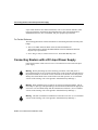
Cisco RPS Support
The Cisco 4000-M, 4500-M, or 4700-M router now supports connection to the Cisco
Redundant Power System (RPS). The router supports an RPS in two ways:
•
•
The chassis ships with an RPS adapter plate installed by the factory
The user installs an RPS adapter plate at the site
For more information, refer to the Cisco RPS Hardware Installation Guide and Installing
the Cisco RPS Adapter Plate in Cisco 4000 Routers. This section provides an overview of
the Cisco RPS and describes basic features.
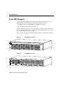
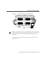
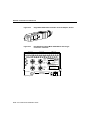
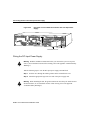
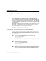
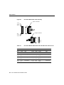
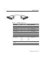
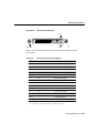
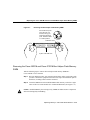
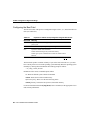
Figure 1-3 shows the front panel of the Cisco RPS, and Figure 1-4 shows the rear panel.
DC STATUS
1
2
3
4
FAN
Figure 1-4
AC INPUT 1
100-200 V~ 50/60 Hz
10-5 A 1000 W
AC INPUT 2
100-200 V~ 50/60 Hz
10-5 A 1000 W
TEMP
H9588
Cisco RPS Front Panel
Cisco RPS Rear Panel
DC OUTPUT 1
1-26 Cisco 4000 Series Installation Guide
DC OUTPUT 2
DC OUTPUT 3
DC OUTPUT 4
H9589
Figure 1-3
Cisco RPS Support
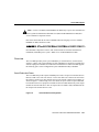
Caution Use the Cisco RPS (model PWR600-AC-RPS) only to power the external device.
Seul le système d’alimentation redondant Cisco (RPS modèle PWR600-AC-RPS) doit
servir à alimenter le dispositif externe.
Das externe Gerät darf nur mit einer redundanten Stromversorgung von Cisco, Modell
PWR600-AC-RPS, betrieben werden.
Para alimentar el dispositivo externo, usar exclusivamente el sistema de alimentación
redundante (redundant power system = RPS) Cisco, modelo PWR600-AC-RPS.
Overview
The Cisco RPS provides power system redundancy to external devices (such as routers,
switches, or hubs). The system includes two fully redundant AC input power modules and
four DC output power modules for connection to external devices. The Cisco RPS supports
the following power source configurations: quasi-redundant and fully redundant.
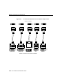
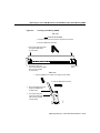
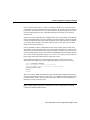
Quasi-Redundant Power
The Cisco RPS can provide a quasi-redundant power source for up to four external devices
that use 150W or less each. You can use a one-to-one cable (one connector at each end of
the cable) to connect up to four external devices to the four DC output power modules, as
shown in Figure 1-5. When using one-to-one cables, the power source is quasi-redundant
because there are two AC input power modules for the Cisco RPS and one DC power output
module for each external device. The AC input to the Cisco RPS is fully redundant, but the
DC output to the external devices is not.
Figure 1-5
Quasi-Redundant Configuration
Overview of the Cisco 4000 Series Routers 1-27
Cisco RPS Support
AC input
AC
NM3998
AC
DC
DC
DC
Cisco RPS
DC
DC output
External devices
150W or less
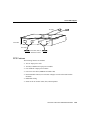
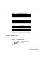
Fully Redundant Power
The Cisco RPS can provide a fully redundant power source for up to two Cisco 4000 series
routers. You can use a two-to-one cable to connect up to two external devices to the four
DC output power modules on the rear panel of the Cisco RPS, as shown in Figure 1-6. The
two-to-one cable is a Y-shaped cable with two connectors at one end of the cable and one
connector at the other end. Two connectors at one end of the Y-shaped cable connect to two
DC output power modules. The other end of the cable connects to one external device.
When using two-to-one cables, the power source is fully redundant because there are two
AC input modules and two DC output power modules connected to each external device. If
any power module fails, there is a full backup.
Figure 1-6
Fully Redundant Configuration
1-28 Cisco 4000 Series Installation Guide
Cisco RPS Support
AC input
AC
NM3999
AC
DC
DC
Cisco RPS
DC
DC
DC output
Cisco 2500, 3600, or
4000 series routers
RPS Features
The following features are standard:
•
•
•
•
•
Two AC input power cords
•
•
Redundant cooling
Two fully redundant AC input power modules
Four 150W DC output power modules
Four one-to-one cables (PWR600-AC-RPS-CAB)
Rack-mountable chassis (two rack units in height, 19-inch rack-mount brackets
included)
LEDs for the AC and DC status, fans, and temperature
Overview of the Cisco 4000 Series Routers 1-29
Cisco RPS Support
1-30 Cisco 4000 Series Installation Guide
2
CHAPT E R
Preparing to Install
Cisco 4000 Series Routers
This chapter includes information you need before you install your Cisco 4000 series
router. It includes the following sections:
•
•
•
•
•
•
Safety Recommendations
General Site Requirements
Installation Checklist
Site Log
Required Tools and Equipment
Inspecting the System
Safety Recommendations
The following guidelines will help to ensure your safety and protect the equipment.
•
•
Keep the chassis area clear and dust-free during and after installation.
Turn the power supply off and unplug the power cord before opening the chassis.
Warning Before working on a chassis or working near power supplies, unplug the power
cord on AC units; disconnect the power at the circuit breaker on DC units. (To see translated
versions of this warning, refer to the appendix “Translated Safety Warnings.”)
•
Keep tools and chassis components away from walk areas.
Preparing to Install Cisco 4000 Series Routers 2-1
Safety Recommendations
•
Do not wear loose clothing that could get caught in the chassis. Fasten your tie or scarf
and roll up your sleeves.
Warning Before working on equipment that is connected to power lines, remove jewelry
(including rings, necklaces, and watches). Metal objects will heat up when connected to
power and ground and can cause serious burns or weld the metal object to the terminals.
(To see translated versions of this warning, refer to the appendix “Translated Safety
Warnings.”)
•
Wear safety glasses when working under any conditions that might be hazardous to your
eyes.
•
Do not perform any action that creates a potential hazard to people or makes the
equipment unsafe.
Warning This equipment is intended to be grounded. Ensure that the host is connected to
earth ground during normal use. (To see translated versions of this warning, refer to the
appendix “Translated Safety Warnings.”)
Safety with Electricity
Follow these guidelines when working on equipment powered by electricity:
•
Locate the emergency power-off switch in the room in which you are working. Then, if
an electrical accident occurs, you can act quickly to shut the power off.
•
•
Before working on the system, turn off the power and unplug the power cord.
Disconnect all power before doing the following:
— Installing or removing a chassis
— Working near power supplies
•
Do not work alone if potentially hazardous conditions exist.
2-2 Cisco 4000 Series Installation Guide
Safety Recommendations
•
•
Never assume that power is disconnected from a circuit. Always check.
•
If an electrical accident occurs, proceed as follows:
Look carefully for possible hazards in your work area, such as moist floors, ungrounded
power extension cables, and missing safety grounds.
— Use caution; do not become a victim yourself.
— Turn off power to the system.
— If possible, send another person to get medical aid. Otherwise, assess the victim’s
condition and then call for help.
— Determine if the person needs rescue breathing or external cardiac compressions;
then take appropriate action.
In addition, use the guidelines that follow when working with any equipment that is
disconnected from a power source, but still connected to telephone wiring or other network
cabling.
•
Never install telephone wiring during a lightning storm.
Warning Do not work on the system or connect or disconnect cables during periods of
lightning activity. (To see translated versions of this warning, refer to the appendix
“Translated Safety Warnings.”)
•
Never install telephone jacks in wet locations unless the jack is specifically designed for
wet locations.
•
Never touch uninsulated telephone wires or terminals unless the telephone line is
disconnected at the network interface.
•
Use caution when installing or modifying telephone lines.
Preparing to Install Cisco 4000 Series Routers 2-3
General Site Requirements
Preventing Electrostatic Discharge Damage
Electrostatic discharge (ESD) can damage equipment and impair electrical circuitry. It
occurs when electronic printed circuit cards are improperly handled and can result in
complete or intermittent failures. Always follow ESD prevention procedures when
removing and replacing cards. Ensure that the router chassis is electrically connected to
earth ground. Wear an ESD-preventive wrist strap, ensuring that it makes good skin contact.
Connect the clip to an unpainted surface of the chassis frame to safely channel unwanted
ESD voltages to ground. To properly guard against ESD damage and shocks, the wrist strap
and cord must operate effectively. If no wrist strap is available, ground yourself by touching
the metal part of the chassis.
For the safety of your equipment, periodically check the resistance value of the
antistatic strap, which should be between 750 kilohm and 10 megohm.
Caution
General Site Requirements
This section describes the requirements your site must meet for safe installation and
operation of your system. Ensure that your site is properly prepared before beginning
installation.
The router can be placed on a desktop or rack-mounted in a data processing or lab
environment. The system can be mounted in either a standard or telco rack. Optional
rack-mount kits are available.
Site Environment
The location of individual chassis and the layout of your equipment rack or wiring room
are extremely important for proper system operation. Equipment placed too close together,
inadequate ventilation, and inaccessible panels can cause system malfunctions and
shutdowns, and can make system maintenance difficult.
When planning your site layout and equipment locations, use the precautions described in
the next section, “Site Configuration Precautions,” to help avoid equipment failures and
reduce the possibility of environmentally caused shutdowns. If you are currently
experiencing shutdowns or unusually high errors with your existing equipment, these
precautions will help you isolate the cause of failures and prevent future problems.
2-4 Cisco 4000 Series Installation Guide
General Site Requirements
Site Configuration Precautions
The following precautions will help you plan an acceptable operating environment for your
router and will help you avoid environmentally caused equipment failures:
•
Remember that electrical equipment generates heat. Ambient air temperature might not
be adequate to cool equipment to acceptable operating temperatures without adequate
circulation. Ensure that the room in which your system operates has adequate
circulation.
•
Never place chassis side by side because the heated exhaust air from one chassis can be
drawn into the intake port of the next.
•
Always follow the ESD-prevention procedures in the section “Preventing Electrostatic
Discharge Damage” earlier in this chapter to avoid damage to equipment. Damage from
static discharge can cause immediate or intermittent equipment failure.
•
Ensure that the chassis cover and network processor module rear panels are secure. The
chassis is designed to allow cooling air to flow within it. An open chassis allows air
leaks, which may in turn interrupt and redirect the flow of cooling air across internal
components.
•
Check the power at your site to ensure that you are receiving “clean” power (free of
spikes and noise). Install a power conditioner if necessary.
Warning The device is designed to work with TN power systems. (To see translated
versions of this warning, refer to the appendix “Translated Safety Warnings.”)
•
Install proper grounding to avoid damage from lightning and power surges.
Preparing to Install Cisco 4000 Series Routers 2-5
General Site Requirements
Equipment Racks
The following tips will help you plan an acceptable equipment rack configuration:
•
Enclosed racks must have adequate ventilation. Ensure that the rack is not overly
congested because each unit generates heat. An enclosed rack should have louvered
sides and a fan to provide cooling air.
•
When mounting a chassis in an open rack, ensure that the rack frame does not block the
intake or the exhaust ports. If the chassis is installed on slides, check the position of the
chassis when it is seated all the way into the rack.
•
In an enclosed rack with a ventilation fan in the top, excessive heat generated by
equipment near the bottom of the rack can be drawn upward and into the intake ports of
the equipment above.
•
Baffles can help to isolate exhaust air from intake air, which also helps to draw cooling
air through the chassis. The best placement of the baffles depends on the airflow patterns
in the rack, which can be found by experimenting with different configurations.
•
When equipment installed in a rack, particularly in an enclosed rack, fails, try operating
the equipment by itself, if possible. Turn off other equipment in the rack (and in adjacent
racks) to allow the unit under test a maximum of cooling air and clean power.
Power Supply Features
Following are features of the router power supply:
•
•
Autoranging power supply (200W, 100 to 240 VAC, 50 to 60 Hz, 40 to 72 VDC)
6-foot electrical power cord
Warning Do not touch the power supply when the power cord is connected. For systems
with a power switch, line voltages are present within the power supply even when the power
switch is off and the power cord is connected. For systems without a power switch, line
voltages are present within the power supply when the power cord is connected. (To see
translated versions of this warning, refer to the appendix “Translated Safety Warnings.”)
2-6 Cisco 4000 Series Installation Guide
Installation Checklist
Installation Checklist
The Installation Checklist lists the procedures for initial hardware installation of a new
router. Make a copy of this checklist and mark the entries as you complete each procedure.
Include a copy of the checklist for each system in your Site Log. (See the next section “Site
Log.”)
Installation checklist for site______________________________________________
Task
Verified by
Date
Installation checklist copied
Background information placed in Site Log
Site power voltages verified
Installation site prepower check completed
Required tools available
Additional equipment available
Cisco 4000 series router received
Cisco 4000 Series Installation Guide (this manual)
received
Cisco Information Packet received
Optional ordered CD or printed documentation
received
Chassis components verified
Initial electrical connections established
ASCII terminal attached to console port, or modem
attached to console port (for remote configuration)
Signal distance limits verified
Startup sequence steps completed
Initial system operation verified
Software image verified
Preparing to Install Cisco 4000 Series Routers 2-7
Site Log
Site Log
The Site Log provides a historical record of all actions relevant to the router. Keep it in an
accessible place near the chassis where anyone who performs tasks has access to it. Use the
Installation Checklist to verify steps in the installation and maintenance of your router. Site
Log entries might include the following:
•
Installation progress—Make a copy of the Installation Checklist and insert it into the
Site Log. Make entries as each procedure is completed.
•
Upgrades and removal or replacement procedures—Use the Site Log as a record of
ongoing router maintenance and expansion history. Each time a procedure is performed
on the router, update the Site Log to reflect the following:
— Additional network processor modules installed
— Removal or replacement of network processor modules
— Configuration changes
— Maintenance schedules and requirements
— Maintenance procedures performed
— Intermittent problems
— Related comments
Warning Ultimate disposal of this product should be handled according to all national
laws and regulations. (To see translated versions of this warning, refer to the appendix
“Translated Safety Warnings.”)
Required Tools and Equipment
You need the following tools and equipment to install the router:
•
•
•
ESD cord and wrist strap
Screwdrivers, Number 1 and Number 2 Phillips
One serial port adapter cable for each serial port to connect the port with the remote
device or network
2-8 Cisco 4000 Series Installation Guide
Inspecting the System
In addition, you might need the following additional external equipment:
•
•
Data service unit (DSU) to connect each serial port to an external network.
•
•
•
Ethernet transceiver.
To connect a serial port to a T1 network, you need a T1 channel service unit/data service
unit (CSU/DSU) that converts the High-Level Data Link Control (HDLC) synchronous
serial data stream into a T1 data stream with the correct framing and ones density.
(Some telephone systems require a minimum number of one bit per time unit in a data
stream, called ones density.) Several T1 CSU/DSU devices are available as additional
equipment, and most provide either a V.35, EIA/TIA-449, or EIA-530 electrical
interface.
Network Terminator 1 (NT1) for BRI connections in North America.
Before installing a G.703/G.704 network processor module, ensure that you have one
of the following adapter cables:
— 75-ohm, unbalanced adapter cable (CAB-E1-BNC-3M)
— 120-ohm, balanced adapter cable (CAB-E1-TWINAX-3M)
Inspecting the System
Before unpacking the system, make certain that you are ready to install it. If the final
installation site is not ready, keep the chassis in its shipping container to prevent accidental
damage. After determining where you want the system installed, proceed with the
unpacking.
The router, cables, publications, CD, and any optional equipment you ordered might be
shipped in more than one container. When you unpack each shipping container, check the
packing list to ensure that you received all of the following items:
•
•
•
•
Router
6-foot (1.8-meter) power cord
Bag of rubber feet for desktop mounting
Optional equipment (which might include network connection cables)
Preparing to Install Cisco 4000 Series Routers 2-9
Inspecting the System
•
•
•
This publication
Cisco Information Packet
Optional companion publications, or the Cisco Connection Documentation, Enterprise
Series CD, as specified on your order
Inspect all items for shipping damage. If anything appears damaged, or if you encounter
problems when installing or configuring your system, contact a customer service
representative. Also, please complete and mail your product registration (see the
publication Cisco Information Packet).
2-10 Cisco 4000 Series Installation Guide
3
CHAPT E R
Configuring the Cisco 4000
Series Chassis
This chapter describes the tasks that should be completed before you connect a Cisco 4000
series router to your network. It contains the following sections:
•
•
•
•
Accessing the Internal Components of the Router
Replacing Network Processor Modules
Replacing the Component Tray
Rack-Mount and Wall-Mount Installation
Accessing the Internal Components of the Router
You must open the chassis to gain access to the router’s internal components—the network
processor modules, boot ROMs, and jumpers.
Refer to the section “Required Tools and Equipment” in the chapter “Preparing to Install
Cisco 4000 Series Routers” for the tools needed to complete the procedures in this chapter.
Warning Before opening the chassis, disconnect the telephone-network cables to avoid
contact with telephone-network voltages. (To see translated versions of this warning, refer
to the appendix “Translated Safety Warnings.”)
Warning Do not work on the system or connect or disconnect cables during periods of
lightning activity. (To see translated versions of this warning, refer to the appendix
“Translated Safety Warnings.”)
Configuring the Cisco 4000 Series Chassis 3-1
Accessing the Internal Components of the Router
Warning Do not touch the power supply when the power cord is connected. For systems
with a power switch, line voltages are present within the power supply even when the power
switch is off and the power cord is connected. For systems without a power switch, line
voltages are present within the power supply when the power cord is connected. (To see
translated versions of this warning, refer to the appendix “Translated Safety Warnings.”)
Warning Before working on a chassis or working near power supplies, unplug the power
cord on AC units; disconnect the power at the circuit breaker on DC units. (To see translated
versions of this warning, refer to the appendix “Translated Safety Warnings.”)
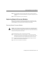
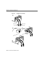
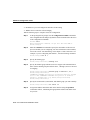
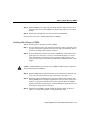
Removing the Component Tray
Some Cisco 4000 series routers have a safety latch tab on the chassis that affects removing
the component tray. (See Figure 3-1 and Figure 3-2.)
If you have a chassis with a safety latch tab, follow the procedure in the next section
“Removing the Component Tray from a Chassis with a Safety Latch.”
If you have a chassis without a safety latch tab, follow the procedure in the section
“Removing the Component Tray from a Chassis without a Safety Latch.”
Removing the Component Tray from a Chassis with a Safety Latch
Take the following steps to remove the component tray from a chassis with a safety latch:
Step 1 Turn OFF the system power.
Step 2 Put on your ESD-preventive wrist strap.
Step 3 Remove all network and power cables.
Step 4 Loosen the nonremovable chassis release screw on the rear panel of the chassis.
(See Figure 3-1.)
Step 5 Pull on the handle located on the upper right corner of the chassis to slide the
component tray out of the chassis shell until the safety latch catches. (See
Figure 3-1.)
3-2 Cisco 4000 Series Installation Guide
Accessing the Internal Components of the Router
Warning Before releasing the safety latch, support the component tray from underneath,
either on your work surface or with your hands, to prevent personal injury. (See Figure 3-1.)
Figure 3-1
Component Tray Removal for Chassis With a Safety Latch
Step 6 Support the component tray with one hand, push down on the safety latch tab, and
pull the component tray out the rest of the way.
Step 7 Set the component tray on your work surface.
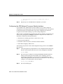
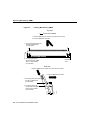
Removing the Component Tray from a Chassis without a Safety Latch
Take the following steps to remove the component tray from a chassis without a safety
latch:
Configuring the Cisco 4000 Series Chassis 3-3
Accessing the Internal Components of the Router
Step 1 Turn OFF the system power.
Step 2 Put on your ESD-preventive wrist strap.
Step 3 Remove all network and power cables.
Step 4 Loosen the nonremovable chassis release screw on the rear panel of the chassis.
(See Figure 3-2.)
Figure 3-2
Component Tray Removal for Chassis Without a Safety Latch
Caution Support the component tray from underneath, either on your work surface or
with your hands, to prevent it from falling. (To see translated versions of this warning, refer
to the appendix “Translated Safety Warnings.”)
3-4 Cisco 4000 Series Installation Guide
Replacing Network Processor Modules
Step 5 Pull on the handle located on the upper right corner of the chassis to slide the
component tray out of the chassis shell while you support the component tray with
one hand.
Step 6 Set the component tray on your work surface.
Replacing Network Processor Modules
When you have removed the component tray from the router, you can remove or add
network processor modules. If you are replacing shared memory single in-line memory
modules (SIMMs), you must first remove the network processor modules.
Removing Network Processor Modules
Caution Some network processor modules are secured to the rear of the chassis with two
external screws. On modules with external rear mounting screws, including multimode
Fiber-Distributed Data Interface (FDDI) modules, these screws must be removed before the
module can be safely lifted out of the chassis.
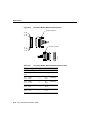
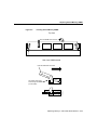
Take the following steps to remove a network processor module:
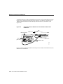
Step 1 Orient the component tray as shown in Figure 3-3, then remove the module
mounting screw from the top of the network processor module. Remove the two
external rear mounting screws if the module has them. Set the screws aside.
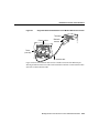
Step 2 Grasp the network processor module handle and pull it straight up to lift the
module out of its connector. (See Figure 3-4.)
Step 3 Place the removed module on an ESD mat.
Configuring the Cisco 4000 Series Chassis 3-5
Replacing Network Processor Modules
Figure 3-3
Cisco 4000-M Component Tray—Typical of Cisco 4000 Series
Caution Do not wiggle the handle when handling the network processor module, and do
not exert any side-to-side pressure because the handle might work loose and damage the
network processor module.
3-6 Cisco 4000 Series Installation Guide
Replacing Network Processor Modules
Figure 3-4
Network Processor Module Components
Caution If any of the network processor module cards have daughter cards projecting at
right angles to the module (see Figure 3-5), be careful not to cause the module to bow
during installation; otherwise the daughter cards can become disconnected. If this happens,
carefully reseat the daughter card connectors by handling the card by its edges without
touching any of the components on the card.
Configuring the Cisco 4000 Series Chassis 3-7
Replacing Network Processor Modules
Figure 3-5
Network Processor Module Daughter Card Installation
Note See the appendix “Cabling Specifications for Cisco 4000 Series Routers” for
network connection pinout information.
Installing Network Processor Modules
Take the following steps to install a network processor module:
Step 1 Hold the network processor module by its handle, align it with the grooves in the
chassis (not shown) and over its connector, and push the module lightly against the
chassis wall. (See Figure 3-4.)
Step 2 Push the network processor module gently into place without bending the
connector pins, inserting the male connector into the female connector on the
motherboard.
3-8 Cisco 4000 Series Installation Guide
Replacing the Component Tray
Step 3 Replace the module mounting screw in its place on the end of the network
processor module. (See Figure 3-4.)
Caution Do not overtighten the module mounting screw. The network processor module
or the underlying motherboard could be damaged. The maximum screw torque is 7 inch-lb.
Step 4 Replace the external rear mounting screws, if used, to attach the module to the rear
of the chassis.
Replacing the Component Tray
Take the following steps to replace the component tray in the chassis shell:
Step 1 Reinsert the component tray into the chassis shell, pushing on the back of the tray
while at the same time pressing on the chassis release screw with the thumb of
your right hand. (See Figure 3-2.)
Step 2 Retighten the chassis release screw.
Rack-Mount and Wall-Mount Installation
You can use optional rack-mount and wall-mount kits to install a Cisco 4000 series router
in a standard 19-inch rack, a 19-inch telco rack, or on a wall. The procedures for the
different installation options involve removing the front panel and component tray from the
chassis, fastening mounting brackets to the chassis, and then installing the empty chassis in
position. You then reinsert the component tray and replace the front panel.
The optional rack-mount and wall-mount kits ship with their own set of installation
instructions. If you are planning to rack-mount or wall-mount the router, do so before
making the network and power connections.
Configuring the Cisco 4000 Series Chassis 3-9
Rack-Mount and Wall-Mount Installation
3-10 Cisco 4000 Series Installation Guide
4
CHAPT E R
Making External Connections
to Cisco 4000 Series Routers
This chapter describes how to connect your Cisco 4000 series router to networks and
external devices, and contains the following sections:
•
•
•
•
•
Preparing to Make Connections
Console Port and Auxiliary Port Connection Considerations
Network Connection Considerations
Connecting Routers with a DC-Input Power Supply
Powering Up the Router
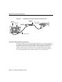
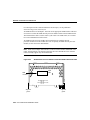
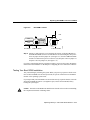
Preparing to Make Connections
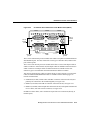
When viewed from the rear, the power cable and power switch appear on the right side of
the router chassis. The system console port, auxiliary port, and network processor module
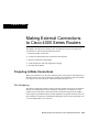
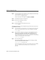
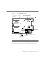
ports appear to the left of the power cable and switch. (See Figure 4-1.)
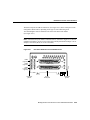
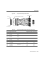
Slot Numbering
The chassis contains slots for three network processor modules. These slots correspond to
the three slot numbers printed on the front panel of the chassis. (See Figure 4-1.) Slot
numbers represent the order in which the system scans the network processor modules.
Network processor module location is not slot dependent. Any module can be moved to any
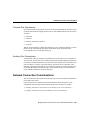
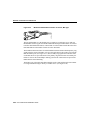
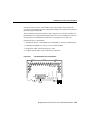
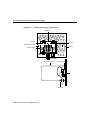
other available slot location. For optimum heat dissipation, use the center slot position, slot
2, for the FDDI module if one is present.
Making External Connections to Cisco 4000 Series Routers 4-45
Preparing to Make Connections
For information on how to remove and replace network processor modules, see the section
“Replacing Network Processor Modules” in the chapter “Configuring the Cisco 4000
Series Chassis.”
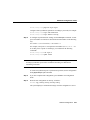
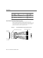
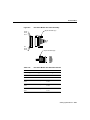
Figure 4-1
Slot 3
Router—Rear View Showing Slot Numbering and Interface Ports
10BaseT
ports
AUI
ports
BRI ports
ISDN
BRI
PORT-7
PORT-6
PORT-5
PORT-4
Chassis
Serial interface ports
release screw
Slot 1
TX
RX
AUI
LNK
POL
Serial
module
Slot 2
PORT-1
10BASE-T
5
PORT-1
4
PORT-0
3
2
1
0
TX
RX
AUI
LNK
POL
PORT-0
ETHERNET AUI
P-3 P-2
P-1 P-0
LP
CN
TD
TC
RD
RC
P-2
P-1`
P-0
H4596
P-3
LP
CN
TD
TC
RD
RC
PORT-2
6
LP
CN
TD
TC
RD
RC
7
LP
CN
TD
TC
RD
RC
PORT-3
Four port
LEDs
BRI
module
Ethernet module
Auxiliary port
Console port
Power
On/off switch
Unit Numbering
Unit numbering allows the system to distinguish between two interfaces of the same type.
As viewed from the rear of the chassis, the unit numbering of the network processor
modules increments from zero counting from the right to left. The system assigns unit
number addresses to these network modules by starting with zero for each module interface
type and numbering from right to left and from bottom to top. The lowest unit number of
that interface type is the module closest to the power supply. For example, the unit number
addresses for the modules in Figure 4-1 are listed in Table 4-1.
4-46 Cisco 4000 Series Installation Guide
Preparing to Make Connections
Table 4-1
Unit Numbering for Serial, Ethernet, and ISDN BRI Modules
Slot Number
Interface and Ports
Unit Address Number
1
Serial port (labeled port 3)
Serial port (labeled port 2)
Serial port (labeled port 1)
Serial port (labeled port 0)
3
2
1
0
2
Ethernet port (top)
Ethernet port (bottom)
1
0
3
BRI port (labeled port 3)
BRI port (labeled port 2)
BRI port (labeled port 1)
BRI port (labeled port 0)
3
2
1
0
If the BRI module in Figure 4-1 were replaced by a second Ethernet module, the unit
addresses would be as listed in Table 4-2.
Table 4-2
Unit Numbering for Serial and Two Ethernet Modules
Slot Number
Interface and Ports
Unit Address Number
1
Serial port (labeled port 3)
Serial port (labeled port 2)
Serial port (labeled port 1)
Serial port (labeled port 0)
3
2
1
0
2
Ethernet port (top)
Ethernet port (bottom)
1
0
3
Ethernet port (top)
Ethernet port (bottom)
3
2
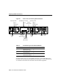
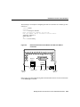
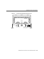
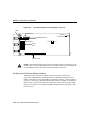
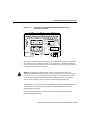
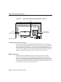
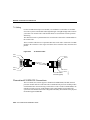
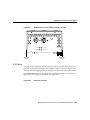
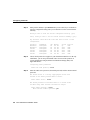
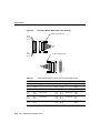
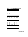
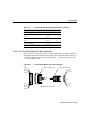
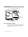
Figure 4-2 shows a chassis configured with three Ethernet modules.The unit numbering of
these modules would be as listed in Table 4-3.
Making External Connections to Cisco 4000 Series Routers 4-47
Preparing to Make Connections
Figure 4-2
100 MB Ethernet module
Ethernet module
Chassis
Slot 2
release screw
Slot 3
Slot 1
AUI ports
TX
RX
AUI
LNK
POL
AUI ports
TX
RX
AUI
LNK
POL
PORT-1
100 MB ETHERNET
RJ45(GRN)
MII (YEL)
10BASE-T
PORT-0
TX
RX
AUI
LNK
POL
LINK
ETHERNET AUI
RX
TX
(RJ45
ONLY)
(RJ45
ONLY)
100BaseTX
PORT-1
10BASE-T
MEDIUM INDEPENDENT INTERFACE
(MII)
TX
RX
AUI
LNK
POL
AUX
PORT-0
ETHERNET AUI
CONSOLE
INPUT 100-240VAC
100BaseTX
port with
RJ-45 connector
10BaseT
ports
Console port
10BaseT
ports
50/60HZ 3.0-1.5 AMPS
H4597
Ethernet module
Router—Rear View Showing Ethernet Modules
On/off
120 VAC switch
100BaseTX
port with
MII connector
Table 4-3
Unit Numbering for Three Ethernet Modules
Slot Number
Interface and Port
Unit Address Number
1
Ethernet port (top)
Ethernet port (bottom)
1
0
2
Fast Ethernet port
2
3
Ethernet port (top)
Ethernet port (bottom)
4
3
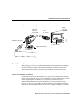
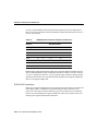
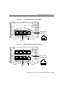
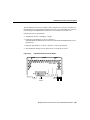
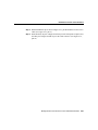
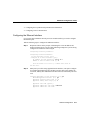
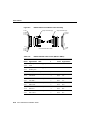
One final example involves two serial modules (NP-2T16S, each with dual high-speed
ports and 16 low-speed ports) and a dual Ethernet module.Figure 4-3 shows the router rear
view and Table 4-4 describes the slot numbers and unit number assignments.
4-48 Cisco 4000 Series Installation Guide
Preparing to Make Connections
Figure 4-3
Router—Rear View Showing Ethernet and Serial Modules
Slot 3
2T16S
serial
module
Slot 2
Slot 1
2T16S
serial
module
10BaseT Ethernet
module
ports
TX
RX
AUI
LNK
POL
PORT-1
10BASE-T
P1
P2
TX
RX
AUI
LNK
POL
PORT-0
P1
P2
SERIAL
AUX
CONSOLE
INPUT 100-240VAC
Auxiliary port
Table 4-4
Console port
50/60HZ 3.0-1.5 AMPS
H10587
SERIAL
On/off switch
Power
Unit Numbering for Ethernet and Serial Modules
Slot Number
Interface and Connector
Unit Address Number
1
Serial high-speed connector (right)
Serial high-speed connector (left)
Low-speed connector (middle)
Low-speed connector (top)
0
1
2–9
10-17
2
Ethernet connector (top)
Ethernet connector (bottom)
1
0
3
Serial high-speed connector (right)
Serial high-speed connector (left)
Low-speed connector (middle)
Low-speed connector (top)
18
19
20–27
28-35
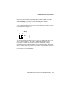
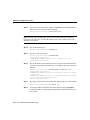
Use of the Slot Filler Panel
If the router is configured with fewer than three network processor modules, you must place
a slot filler panel in the open slot to ensure proper airflow. Figure 4-4 shows a slot filler
panel.
Making External Connections to Cisco 4000 Series Routers 4-49
Console Port and Auxiliary Port Connection Considerations
Figure 4-4
Slot Filler Panel
H1034a
Available Slot
Alignment
groove
Mounting
screw locations
Alignment
groove
Console Port and Auxiliary Port Connection
Considerations
This section describes the console and auxiliary ports found on all Cisco 4000 series
routers.
Warning The ports labeled “Ethernet,” “10BaseT,” “Token Ring,” “Console,” and “AUX”
are safety extra-low voltage (SELV) circuits. SELV circuits should only be connected to
other SELV circuits. Because the BRI circuits are treated like telephone-network voltage,
avoid connecting the SELV circuit to the telephone network voltage (TNV) circuits. (To see
translated versions of this warning, refer to the appendix “Translated Safety Warnings.”)
4-50 Cisco 4000 Series Installation Guide
Network Connection Considerations
Console Port Connections
Each router includes an asynchronous router console port (female DB-25 connector) wired
as a data communications equipment (DCE) device. The default parameters for this port are
as follows:
•
•
•
•
9600 baud
8 data bits
No parity generated or checked
2 stop bits
Table B-1 in the appendix “Cabling Specifications for Cisco 4000 Series Routers,” lists the
pinouts for the Cisco 4000-M console port and Table B-2 lists the pinouts for the
Cisco 4500-M and Cisco 4700-M console port.
Auxiliary Port Connections
A male DB-25 connector auxiliary port (labeled AUX on the chassis rear) is included on
all router units. The auxiliary port is a shared-memory data terminal equipment (DTE) port
to which you can attach an EIA/TIA-232 connector from a channel service unit/data service
unit (CSU/DSU), a modem, or protocol analyzer for network access. Table B-1 in the
appendix “Cabling Specifications for Cisco 4000 Series Routers,” lists the pinouts for the
Cisco 4000-M auxiliary port and Table B-3 lists the pinouts for the Cisco 4500-M and
Cisco 4700-M asynchronous serial auxiliary port.
Network Connection Considerations
This section describes the considerations for each type of network connection available for
Cisco 4000 series routers.
For network processor modules released after publication of this document, see the
configuration notes that ship with the chassis and the spare modules, for example
•
•
Installing Fast Ethernet Network Processor Modules in the Cisco 4000 Series
Installing 2T16S Network Processor Modules in the Cisco 4000 Series
Making External Connections to Cisco 4000 Series Routers 4-51
Network Connection Considerations
•
Installing and Configuring HSSI Network Processor Modules in Cisco 4000 Series
Routers
Ethernet Connections
This section describes the single-port, dual-port, and six-port Ethernet network processor
modules.
Warning The ports labeled “Ethernet,” “10BaseT,” “Token Ring,” “Console,” and “AUX”
are safety extra-low voltage (SELV) circuits. SELV circuits should only be connected to
other SELV circuits. Because the BRI circuits are treated like telephone-network voltage,
avoid connecting the SELV circuit to the telephone network voltage (TNV) circuits. (To see
translated versions of this warning, refer to the appendix “Translated Safety Warnings.”)
Note The single-port Ethernet network processor module is not supported on the
Cisco 4500-M and Cisco 4700-M. The six-port Ethernet network processor module is not
supported on the Cisco 4000-M.
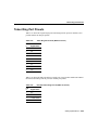
Single-Port Ethernet Module Connections
Each single-port Ethernet network processor module has an Ethernet attachment unit
interface (AUI) connector and a 10BaseT connector. (See Figure 4-5.) (Only one connector
on the module can be used at a time.) Use either an IEEE 802.3 AUI or a 10BaseT cable to
make the connection.
Selecting the Media Type
The media type connection, AUI or 10BaseT, is selected by the media-type command.
Enter the media-type command in the router’s configuration file to configure your selection
of AUI or 10BaseT on the desired interface. The syntax of the media-type command is as
follows:
media-type aui
media-type 10baset
4-52 Cisco 4000 Series Installation Guide
Network Connection Considerations
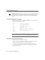
The following is an example of configuring the Ethernet 0 interface for a media type AUI
connection:
router> enable
Password:
router# configure terminal
Enter configuration commands, one per line.
Edit with DELETE, CTRL/W, and CTRL/U; end with CTRL/Z
interface ethernet 0
media-type aui
^z
router# write memory
Figure 4-5
Ethernet Network Processor Module with AUI and 10BaseT
Connectors
AUI
LEDs
AUI
TX
RX
LNK
POL
10BaseT port
Alignment
groove
H1043a
Ethernet
10BaseT
AUI port
Alignment
groove
Refer to the Cisco IOS configuration guides and command references for more information
on the media-type command.
Making External Connections to Cisco 4000 Series Routers 4-53
Network Connection Considerations
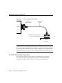
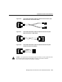
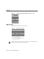
An Ethernet transceiver cable with thumbscrew connectors can be connected directly to the
router port by replacing the slide latch with a jackscrew (provided in a separate bag). A
10BaseT transition cable can connect directly from the router to your network. (See
Figure 4-6.)
Figure 4-6
Single-Port Ethernet Network Processor Module 10BaseT Port
Connection
10BaseT hub
Ethernet module
AUI
Router
(rear view)
10BASET
10BaseT cable
H1524a
AUX
Figure 4-7 shows a single-port Ethernet network processor module with an Ethernet (AUI)
connection to a transceiver.
4-54 Cisco 4000 Series Installation Guide
Network Connection Considerations
Figure 4-7
Single-Port Ethernet Network Processor Module AUI Port Connection
Ethernet module
Slide-latch
connector
H1525a
Transceiver
AUI
Router
(rear view)
AUX
18" transition cable
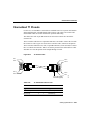
Figure 4-8 shows the transition cable used as a flexible extension of the Ethernet port
allowing an Ethernet transceiver cable with a slide-latch connector to mate with the female
end of the 18-inch transition cable.
Making External Connections to Cisco 4000 Series Routers 4-55
Network Connection Considerations
Extending the Transition Cable from the Ethernet Port
Slide-latch
connector
Router
(rear view)
Ethernet
module
TX
RX
AUI
LNK
POL
Slide-latch
connector
Ethernet (AUI)
transceiver
H4604
Figure 4-8
PORT-1
10BASE-T
TX
RX
AUI
LNK
POL
PORT-0
ETHERNET AUI
AUX
18" transition cable
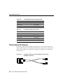
Dual-Port Ethernet Module Connections
The dual-port Ethernet network processor module has ports for two network connections.
(See Figure 4-9.) The top port is labeled PORT-1, and the lower port is labeled PORT-0. On
the dual-port Ethernet network processor module, either the Ethernet connector or the
10BaseT connector can be used, but not both. For example, Ethernet port 0 could be
attached to either a 10BaseT connector or to an AUI connector, and similarly, Ethernet
port 1 could be attached to either a 10BaseT connector or to an AUI connector.
4-56 Cisco 4000 Series Installation Guide
Network Connection Considerations
Figure 4-9
Dual-Port Ethernet Network Processor Module with AUI and 10BaseT
Connectors
TX
RX
AUI
LNK
POL
PORT-1
10BASE-T
PORT-0
ETHERNET AUI
LEDs
Alignment
groove
10BaseT ports
AUI ports
Alignment
groove
H1480a
TX
RX
AUI
LNK
POL
Six-Port Ethernet Module
The six-port Ethernet network processor module has ports for six network connections.
(See Figure 4-10.) The port numbering is as shown on the label on the lower right of the
module. Only 10BaseT connections are supported on the six-port Ethernet network
processor module.
Note The six-port Ethernet module is not supported on the Cisco 4000 and Cisco 4000-M.
Making External Connections to Cisco 4000 Series Routers 4-57
Network Connection Considerations
Six-Port Ethernet Network Processor Module
PORT-5
TX
TX
PORT-4
TX
RX
RX
RX
LK
LK
LK
PORT-2
TX
TX
PORT-1
TX
RX
RX
RX
LK
LK
LK
PORT-3
PORT-0
SIX
ETHERNET
PORTS
5 4 3
2 1 0
LEDs
LEDs
RJ-45
RJ-45
RJ-45
10BaseT ports 10BaseT ports 10BaseT ports
H3896
Figure 4-10
Port
numbering
LEDs
Alignment
groove
Alignment
groove
Token Ring Connections
The dual-port Token Ring network processor module has two standard 9-pin connectors.
(See Figure 4-11.) The single-port Token Ring network processor module has one standard
9-pin connector. (See Figure 4-12.)
Warning The ports labeled “Ethernet,” “10BaseT,” “Token Ring,” “Console,” and “AUX”
are safety extra-low voltage (SELV) circuits. SELV circuits should only be connected to
other SELV circuits. Because the BRI circuits are treated like telephone-network voltage,
avoid connecting the SELV circuit to the telephone network voltage (TNV) circuits. (To see
translated versions of this warning, refer to the appendix “Translated Safety Warnings.”)
4-58 Cisco 4000 Series Installation Guide
Network Connection Considerations
Figure 4-11
Dual-Port Token Ring Module Network Connector
RING A
H1980
IN-RING A
RING B
IN-RING B
Token Ring
16MBPS
LEDs
Token Ring port
Alignment
groove
DB-9 female
Token Ring port
Alignment
groove
Making External Connections to Cisco 4000 Series Routers 4-59
Network Connection Considerations
Alignment
groove
Token Ring
LEDs
Token Ring port
(2 green)
H1042a
IN-RING
Token Ring Module Network Connector
16MBPS
Figure 4-12
Alignment
groove
Use a standard 9-pin Token Ring lobe cable to connect the router directly to a media
attachment unit (MAU). (See Figure 4-13.)
4-60 Cisco 4000 Series Installation Guide
Network Connection Considerations
Figure 4-13
Token Ring Cable Connections
Router
(rear view)
9-pin
D connector
H1569a
Token Ring
lobe cable
(not included)
IEEE 802.5 connector
Token Ring port
Media attachment unit
Serial Connections
When setting up your router, consider distance limitations and potential electromagnetic
interference (EMI) as defined in the Electronic Industries Association’s (EIA) and
Telecommunications Industry Association (TIA) standards, such as EIA/TIA-232.
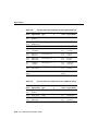
Serial Line Distance Limitations
Serial signals can travel a limited distance at any given bit rate; generally, the slower the
baud rate, the greater the distance. All serial signals are subject to distance limits, beyond
which a signal degrades significantly or is completely lost. Table 4-5 lists the
IEEE-recommended maximum speeds and distances for each serial interface type;
however, you may get good results at speeds and distances greater than those listed. For
instance, the recommended maximum rate for V.35 is 2 Mbps, but 4 Mbps is commonly
Making External Connections to Cisco 4000 Series Routers 4-61
Network Connection Considerations
used. If you understand the electrical problems that might arise and can compensate for
them, you can get good results with rates and distances greater than those shown. However,
do so at your own risk.
Table 4-5
IEEE Standard Transmission Speeds and Distances
EIA/TIA-232
Distance
EIA/TIA-449, X.21, V.35,
EIA-530 Distance
Rate (bps)
Feet
Meters
Feet
Meters
2400
200
60
4100
1250
4800
100
30
2050
625
9600
50
15
1025
312
19200
25
7.6
513
156
38400
12
3.7
256
78
56000
8.6
2.6
102
31
1544000 (T1)
N/A
N/A
50
15
Balanced drivers allow EIA/TIA-449 signals to travel greater distances than EIA/TIA-232.
The recommended distance limits for EIA/TIA-449 shown in Table 4-5 are also valid for
V.35, X.21, and EIA-530. However, you can get good results at distances and rates greater
than those shown in Table 4-5. Typically, EIA/TIA-449 and EIA-530 support 2-Mbps rates,
and V.35 can support 4-Mbps rates.
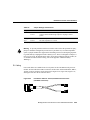
EIA/TIA-232 Connections
EIA/TIA-232 supports unbalanced circuits at signal speeds up to 64 kbps. The network end
of the adapter cable is a standard 25-pin D-shell connector known as a DB-25. (See
Figure 4-14.) The router console and auxiliary ports also use EIA/TIA-232 connections;
however, the serial module ports support synchronous connections, and the console and
auxiliary ports support asynchronous connections.
4-62 Cisco 4000 Series Installation Guide
Network Connection Considerations
Figure 4-14
EIA/TIA-232 Adapter Cable Connectors, Network End
DCE
H1343a
DTE
EIA/TIA-449 Connections
EIA/TIA-449, which supports balanced (EIA/TIA-422) and unbalanced (EIA/TIA-423)
transmissions, is a faster (up to 2 Mbps) version of EIA/TIA-232 that provides more
functions and supports transmissions over greater distances.
The EIA/TIA-449 standard was intended to replace the EIA/TIA-232 standard, but it was
not widely adopted primarily because of the large installed base of DB-25 hardware and
because of the larger size of the 37-pin EIA/TIA-449 connectors, which limited the number
of connections possible (fewer than possible with the smaller, 25-pin EIA/TIA-232
connector).
The network end of the EIA/TIA-449 adapter cable provides a standard 37-pin D-shell
connector. (See Figure 4-15.) EIA/TIA-449 cables are available as either DTE (DB-37
plug) or DCE (DB-37 receptacle).
EIA/TIA-449 Adapter Cable Connectors, Network End
DTE
DCE
H1344a
Figure 4-15
Making External Connections to Cisco 4000 Series Routers 4-63
Network Connection Considerations
V.35 Connections
The V.35 interface is recommended for speeds up to 48 kbps, although in practice it is used
successfully at 4 Mbps.
The network end of the V.35 adapter cable provides a standard 34-pin Winchester-type
connector. (See Figure 4-16.) V.35 cables are available with a standard V.35 plug or
receptacle in either DTE or DCE mode.
Figure 4-16
V.35 Adapter Cable Connectors, Network End
DCE
H1616a
DTE
X.21 Connections
The X.21 interface uses a 15-pin connection for balanced circuits and is commonly used in
the United Kingdom to connect public data networks. X.21 relocates some of the logic
functions to the DTE and DCE interfaces and, as a result, requires fewer circuits and a
smaller connector than EIA/TIA-232.
The network end of the X.21 adapter cable is a standard DB-15 connector.
(See Figure 4-17.) X.21 cables are available as either DTE (DB-15 plug) or DCE (DB-15
receptacle).
4-64 Cisco 4000 Series Installation Guide
Network Connection Considerations
Figure 4-17
X.21 Adapter Cable Connectors, Network End
1
8
15
9
DCE
H1346a
DTE
EIA-530 Connections
EIA-530, which supports balanced transmission, provides the increased functionality,
speed, and distance of EIA/TIA-449 on the smaller, DB-25 connector used for
EIA/TIA-232, instead of the 37-pin connectors used for EIA/TIA-449. Like EIA/TIA-449,
EIA-530 refers to the electrical specifications of EIA/TIA-422 and EIA/TIA-423. Although
the specification recommends a maximum speed of 2 Mbps, EIA-530 is used successfully
at 4 Mbps or faster speeds over short distances.
The EIA-530 adapter cable is available in DTE mode only. The network end of the EIA-530
adapter cable is a standard DB-25 plug commonly used for EIA/TIA-232 connections.
Figure 4-18 shows the DB-25 connector at the network end of the adapter cable.
EIA-530 Adapter Cable Connector, Network End
DTE
H1615a
Figure 4-18
Interference Considerations
When wires are run for any significant distance in an electromagnetic field, interference can
occur between the field and the signals on the wires. This fact has two implications for the
construction of terminal plant wiring:
Making External Connections to Cisco 4000 Series Routers 4-65
Network Connection Considerations
•
Plant cabling can emit radio frequency interference (RFI) if it is unshielded for a
distance exceeding those recommended by the standard.
•
Strong electromagnetic interference, especially as caused by lightning or radio
transmitters, can destroy the EIA/TIA-232 drivers and receivers in a router.
If you use twisted-pair cables in your plant wiring with a good distribution of grounding
conductors, the plant wiring is unlikely to emit radio interference. Ground the conductor
for each data signal when exceeding the distances listed in Table 4-5.
If you have cables exceeding the distances in Table 4-5, or if you have cables that pass
between buildings, then give special consideration to the effect of lightning strikes and
ground loops. The electromagnetic pulse caused by lightning and other high-energy
phenomena can couple enough energy into unshielded conductors to destroy electronic
devices; the potential existence of ground loops are also a threat to electrical components
and to safety. If your site has experienced these problems, then consult experts in lightning
suppression and shielding.
Most data centers cannot resolve the infrequent but potentially catastrophic problems just
described without pulse meters and other special equipment. Take precautions to avoid
these problems by providing a properly grounded and shielded environment, with special
attention to issues of electrical surge suppression. To predict and remedy strong
electromagnetic interference, consult experts in RFI.
Configuring Serial Connections
The four-port serial network processor module ports are DB-60 connectors; the dual serial
network processor module ports are DB-50 connectors. (See Figure 4-19 and Figure 4-21.)
These serial ports can be configured as DTE or DCE, depending on the special serial cable
used.
Figure 4-19 shows port numbering on the four-port serial module.
4-66 Cisco 4000 Series Installation Guide
Network Connection Considerations
Figure 4-19
60-Pin
ports
Four-Port Serial Network Processor Module Ports
PORT-3
PORT-2
PORT-1
PORT-0
60-Pin
ports
P-2
P-1 P-0
LP
CN
TD
TC
RD
RC
P-1`
P-0
H1981
P-3
LP
CN
TD
TC
RD
RC
LP
CN
TD
TC
RD
RC
LP
CN
TD
TC
RD
RC
P-3 P-2
LEDs
The connector on the four-port serial network processor module is upside down.
The cable should match that orientation. Ensure that the 60-pin connectors on the cable and
on the module match. Do not force the cable into the connector upside down. (See
Figure 4-19.)
Caution
Figure 4-20 shows the network connections of the four-port serial network processor
module adapter cables.
Making External Connections to Cisco 4000 Series Routers 4-67
Network Connection Considerations
Figure 4-20
Four-Port Serial Network Processor Module Adapter Cables
H2485
Router connections
EIA/TIA-232
EIA/TIA-449
V.35
X.21
Network connections at the modem or CSU/DSU
4-68 Cisco 4000 Series Installation Guide
EIA-530
Network Connection Considerations
The dual serial ports are DB-50 connectors. (See Figure 4-21.) These serial ports can be
configured as DTE or DCE, depending on the type of serial cable being used.
Two LED daughter cards are attached to the front of the dual serial module.
(See Figure 4-22.)
Note If the dual serial port module is labeled with V2, as shown in Figure 4-21, then for
optimum performance, use the version of the cable with the part number ending in -02: for
example, 72-0740-02 (DCE) or 72-0671-02 (DTE).
Dual Serial Network Processor Module Ports
LEDs
(4 green)
DO
TXC
DI
RXC
LEDs
(4 green)
DCD
RS
TS1
TS2
LEDs
(1 yellow,
1 green)
LP
DCE
P-0
Alignment
groove
PORT-1
SERIAL (V2)
PORT-0
P-1
50-Pin
serial ports
H1484a
Figure 4-21
Alignment
groove
Making External Connections to Cisco 4000 Series Routers 4-69
Network Connection Considerations
Figure 4-22
Dual Serial Network Processor Module—Top View
LEDs
Indicates port 0
Mounting
screw location
LED daughter cards
Indicates port 1
J5 J4
Port 1
Port 0
H1036a
Serial
ports
Module handle
Caution Hold the dual serial network processor module carefully by its handle or by the
module’s edge. To prevent damage from stress or from ESD, do not exert force against the
two LED daughter cards, and do not touch the components on the cards.
Configuring the Dual Serial Module Interfaces
The dual serial network processor module contains two jumpers, J4 and J5 (see
Figure 4-22), which determine whether the ports are configured for nonreturn to zero
(NRZ) or nonreturn to zero inverted (NRZI). J4 configures serial port 0, and J5 configures
serial port 1. The factory-configured (default) jumper setting is for NRZ. To configure for
NRZI mode on each port, the jumper must connect pins 1 and 2 of the respective jumper
locations. (See Figure 4-23.) For NRZ (not NRZI), the jumpers that connect pins 2 and 3
can be removed.
4-70 Cisco 4000 Series Installation Guide
Network Connection Considerations
If the network processor module is operating as DTE in NRZI mode, the sense of the
dte-invert-timing command must be manually changed. For instance, if the command
no dte-invert-timing was previously entered in the configuration file, then
dte-invert-timing must be configured for the module to operate as DTE in NRZI mode.
To set the jumpers for NRZI, move the jumpers to the position shown in Figure 4-23 using
the orientation shown in Figure 4-22.
Figure 4-23
J5
Dual Serial Network Processor Module Jumpers, J4 and J5—NRZI
Setting
J4
Port 1
Port 0
H1125a
Pin 1
You must use a special serial cable to connect the router to a modem, CSU/DSU, or other
device as shown in Figure 4-24. This cable, available from your customer service
representative, is normally ordered with the system. See the appendix, “Cabling
Specifications for Cisco 4000 Series Routers,” for more information. Nine different serial
cables are available for the two versions of serial modules: both DTE and DCE versions of
V.35, EIA/TIA-232, EIA/TIA-449, and X.21; and EIA-530 DTE. Note that the cables for
the two versions are not interchangeable.
Making External Connections to Cisco 4000 Series Routers 4-71
Network Connection Considerations
Figure 4-24
Router Serial Cable Connections
Serial port
50-pin connector
Serial transition
cable
H1037a
Chassis
EIA/TIA-232, EIA/TIA-449, V.35,
X.21, or EIA-530 connector
Modem
or
CSU/DSU
Note Serial ports configured as DCE must also be configured with the clockrate
command. An error message will be generated if there is a mismatch between the cable and
the software configuration of the port—for example, if the cable is DTE and the clock rate
is set, or if the cable is DCE and the clock rate is not configured. For more information on
software commands, refer to the Cisco IOS configuration guides and command references.
G.703/G.704 Interface Connections
The G.703/G.704 network processor module is configured at the factory with four
E1-G.703/G.704 interface ports. Each port provides one 15-pin, D-shell (DB-15)
receptacle, which supports only E1-G.703/G.704 interfaces. (See Figure 4-25.)
4-72 Cisco 4000 Series Installation Guide
Network Connection Considerations
Figure 4-25
G.703/G.704 Serial Network Processor Module Ports (DB-15)
E1
PORT-3
DB-15
female
ports
DB-15
female
ports
PORT-2
PORT-1
PORT-0
P-3
Alignment
groove
P-2
LEDs
P-1 P-0
LP
CN
TD
TC
RD
RC
LP
CN
TD
TC
RD
RC
LP
CN
TD
TC
RD
RC
LP
CN
TD
TC
RD
RC
P-3 P-2
P-1`
H2792
E1
P-0
Alignment
groove
The G.703/G.704 network processor module uses a DB-15 receptacle for both the balanced
and unbalanced ports. You must connect the correct type of interface cable; otherwise the
port will not operate.
The G.703/G.704 network processor module end of all E1-G.703/G.704 adapter cables is
a DB-15 connector. At the network end, the adapter cable for unbalanced connections uses
a BNC connector. The adapter cables for balanced mode are available with several
connector types to accommodate connection standards in different countries.
You must use the proprietary cables to connect the E1-G.703/G.704 port to your network.
Cables for balanced and unbalanced modes are available with the following types of
network-end connectors:
•
Unbalanced (75-ohm) coaxial cables with BNC connectors at the network end (used
primarily for connection in the United Kingdom), see Figure 4-26.
•
•
Balanced (120-ohm) with a DB-15 connector at the network end, see Figure 4-27.
Balanced (120-ohm) twinaxial split cable at the network end, with separate transmit and
receive cables, each with a twinax connector, see Figure 4-28.
In addition to these cables, some connections require bare-wire connections (directly to
terminal posts).
Making External Connections to Cisco 4000 Series Routers 4-73
Network Connection Considerations
Following are the available E1-G.703/G.704 module options:
•
•
•
•
•
Four port E1-G.703/G.704, 120-ohm, balanced
Four port E1-G.703/G.704, 75-ohm, unbalanced
E1 cable, TWINAX, 120-ohm, balanced, 5 meters
E1 cable, DB-15, 120-ohm, balanced, 5 meters
E1 cable, BNC, 75-ohm, unbalanced, 5 meters
G.703/G.704 Maximum Cable Lengths
Unbalanced G.703 interfaces allow for a longer maximum cable length than those specified
for balanced circuits. Table 4-6 lists the maximum cable lengths for each E1-G.703/G.704
cable type by the connector used at the network end (away from the network processor
module).
Table 4-6
E1-G.703/G.704 Maximum Cable Lengths
Connection Type
BNC
Twinax
Balanced
–
300 m
Unbalanced
600 m
–
G.703/G.704 Cable Connections
Figure 4-26, Figure 4-27, and Figure 4-28 show the unbalanced and balanced cables used
for connection between the E1-G.703/G.704 port and your network. The port adapter end
of each cable has a DB-15 connector.
4-74 Cisco 4000 Series Installation Guide
Network Connection Considerations
E1-G.703/G.704 Interface Cable for Unbalanced Connections (with
BNC Connectors and Coaxial Cables)
Figure 4-27
E1-G.703/G.704 Interface Cable for Balanced Connections (with
DB-15 Connectors on Both Ends)
Figure 4-28
E1-G.703/G.704 Interface Cable for Balanced Connections (with
Twinax Connectors and Cables)
H2424
H2476
H2421
Figure 4-26
Caution It is a requirement of the statutory approval of the E1-G.703/G.704 interface that
the jackscrews of the connector backshell are securely screwed down while the
E1-G.703/G.704 network processor module is operating.
Making External Connections to Cisco 4000 Series Routers 4-75
Network Connection Considerations
FDDI Connections
Multimode FDDI network processor modules provide either a dual-attachment station
(DAS) or a single-attachment station (SAS). Single-mode FDDI network processor
modules provide a DAS. Following are the available FDDI module options:
•
•
•
Multimode dual-attachment
Multimode single-attachment
Single-mode dual-attachment
The multimode FDDI network processor module consists of two cards, each with a
multimode transceiver, with one card fitting on top of the other. The bottom card is the SAS
and contains the physical sublayer (PHY)-A port. If the DAS option is included, the PHY-B
port is located on the module’s top card.
Distance Limitations for FDDI Connections
The distance limitations for single-mode and multimode FDDI stations are shown in
Table 4-7. If the distance between two connected stations is greater than the maximum
distance shown, significant signal loss can result. The single-mode transmitter and the
multimode transceiver each provide 11 decibels of optical power.
Table 4-7
FDDI Maximum Transmission Distances
Transceiver Type
Maximum Distance Between Stations
Single-mode
Up to 6 miles (10 kilometers)
Multimode
Up to 1.2 miles (1.9 kilometers)
FDDI Cable Connections
Older versions of the single-mode network processor module (version 2 or earlier as shown
using the show controller Cisco IOS command) use simplex FC-type connectors (see
Figure 4-29 and Figure 4-33) for the transmit and receive ports. Newer versions of the
single-mode network processor module use simplex SC-type connectors. (See Figure 4-30
4-76 Cisco 4000 Series Installation Guide
Network Connection Considerations
and Figure 4-34.) The connector accepts standard 8.7 to 10/125-micron single-mode
fiber-optic cable. The single-mode interface supports connections at distances up to
six miles (10 kilometers).
Older Version, Single-Mode FDDI Network Interface Connector, FC
Type
Figure 4-30
Newer Version, Single-Mode FDDI Network Interface Connector, SC
Type
H2399
H1348a
Figure 4-29
Newer versions of the single-mode network processor module are shipped with an
FC-to-SC adapter that allows the newer version of the single-mode network processor
module to be used with existing cables installed for the earlier version of the module. (See
Figure 4-31 and Figure 4-32.)
Single-Mode FDDI Network Interface FC-to-SC Adapter, FC End
H6080
Figure 4-31
Making External Connections to Cisco 4000 Series Routers 4-77
Network Connection Considerations
Single-Mode FDDI Network Interface FC-to-SC Adapter, SC End
Figure 4-33
Dual-Attachment Single-Mode FDDI Module with FC-type
Connectors—End View
H6081
Figure 4-32
PHY-B
FDDI WARNING
AVOID EXPOSURE–INVISIBLE
LASER RADIATION IS EMITTED
FROM THESE APERTURES.
1300 NM
PHY–B
RING OP
CLASS 1 LASER PRODUCT
LASERKLASSE 1
PHY-A
CISCO SYSTEMS, INC.
170 WEST TASMAN DRIVE
SAN JOSE, CA 95134-1706
RCVR
PHY–A
RING OP
DATE:
“Complies with FDA Radiation
Performance Standards, 21 CFR,
Subchapter J”
Mounting
screw locations
Alignment groove
4-78 Cisco 4000 Series Installation Guide
Alignment groove
H1614a
XMTR
Network Connection Considerations
Figure 4-34
Dual-Attachment Single-Mode FDDI Module with SC-type
Connectors—End View
PHY-B
FDDI WARNING
AVOID EXPOSURE–INVISIBLE
LASER RADIATION IS EMITTED
FROM THESE APERTURES.
1300 NM
PHY–B
RING OP
CLASS 1 LASER PRODUCT
LASERKLASSE 1
PHY-A
CISCO SYSTEMS, INC.
170 WEST TASMAN DRIVE
SAN JOSE, CA 95134-1706
RCVR
PHY–A
RING OP
DATE:
“Complies with FDA Radiation
Performance Standards, 21 CFR,
Subchapter J”
H6268
XMTR
Mounting
screw locations
Alignment groove
Alignment groove
The single-mode transmitter uses a small laser to transmit the light signal to the ring. Keep
the transmit port covered whenever a cable is not connected to it. Although multimode
transceivers typically use LEDs (not lasers) for transmission, keep open ports covered and
avoid staring into open ports or apertures.
Warning Invisible laser radiation may be emitted from the aperture ports of the
single-mode FDDI products when no fiber cable is connected. Avoid exposure and do not
stare into open apertures. This product meets the Class 1 Laser Emission Requirement
from Center for Devices and Radiological Health (CDRH) FDDI. (To see translated
versions of this warning, refer to the appendix “Translated Safety Warnings.”)
The multimode network processor module connectors are FDDI-standard PHY connectors.
The media interface connector (MIC) connects to FDDI standard 62.5/125-micron
multimode fiber-optic cable.
Figure 4-35 shows the MIC typically used for network and chassis connections in
multimode FDDI applications.
Making External Connections to Cisco 4000 Series Routers 4-79
Network Connection Considerations
Multimode FDDI Network Interface Connector, MIC Type
H1349a
Figure 4-35
The port labeled PHY-A is the bottom port (see Figure 4-33 and Figure 4-36), and port
labeled PHY-B is the top port on both the multimode and single-mode modules. To connect
to another dual-attachment station, connect PHY-A on the module to PHY-B on the other
DAS and PHY-B on the module to PHY-A on the other DAS.
The standard connection scheme for a dual-attachment station dictates that the primary ring
signal enters the router on the PHY-A receive port and returns to the primary ring from the
PHY-B transmit port. (See Figure 4-37.) The secondary ring signal comes into the router
on the PHY-B receive port and returns to the primary ring from the PHY-A transmit port.
Failure to observe this relationship in making your network connections will prevent the
FDDI interface from initializing.
The PHY-S port of the single-attachment module can be connected through a concentrator
to a single-attachment ring or directly to another device. (See Figure 4-38.)
4-80 Cisco 4000 Series Installation Guide
Network Connection Considerations
Figure 4-36
Dual-Attachment Multimode FDDI Module—End View
LEDs (2)
PHY-B
PHY-B
FDDI
PHY-B
RING OP
OPT-BYPASS
Multimode ports
PHY-A
H1400a
PHY-A
RING OP
PHY-A
Optical bypass
switch connector
Mounting
screw locations
Alignment groove
Alignment groove
Figure 4-37
Dual-Attachment FDDI Optical Bypass Switch and PHY Connections
Optical bypass
switch
To
ng
Dual-attachment
multimode
FDDI module
Optical bypass
interface cable
PHY-B
G
RIN
OP
FDDI
OPT-BY
PHY-A
PASS
G
RIN
OP
H1405a
PHY-A
PHY-B
Bypass operation
PHY-B
PHY-A
Mounting
screw locations
Optical
bypass switch
connector (DIN)
Making External Connections to Cisco 4000 Series Routers 4-81
Network Connection Considerations
Figure 4-38
Single-Attachment Multimode FDDI Module—End View
LED
FDDI
OPT-BYPASS
PHY-S
PHY-S
Multimode port
Optical bypass
switch connector
H1401a
PHY-S
RING OPT
Mounting
screw locations
Alignment groove
Alignment groove
Optical Bypass Switch Connections
Both the dual-attachment and single-attachment FDDI modules have an optical bypass
switch connector. An optical bypass switch is a passive optical device powered by the FDDI
module. If a fault in the router occurs, or if power is lost, the optical bypass switch is
enabled, and the ring will be unaffected. The optical bypass switch is automatically enabled
if power is lost. In addition, the system software can enable the optical bypass switch if a
problem is detected or if the operator chooses to take the router out of the ring.
BRI Connections
The Basic Rate Interface (BRI) network processor modules (see Figure 4-40 and
Figure 4-39) support either four or eight BRI ports. Each BRI port is an RJ-45 8-pin
connector. Use an appropriate cable to connect the BRI module directly to an Integrated
Services Digital Network (ISDN) through an ISDN channel service unit/digital service unit
(CSU/DSU) called the NT1. The common carrier will provide the NT1 connection, except
in North America, where the NT1 is customer owned.
4-82 Cisco 4000 Series Installation Guide
Network Connection Considerations
Figure 4-39
Four-Port BRI Network Processor Module
ISDN
BRI
PORT-7
PORT-6
PORT-5
PORT-4
Network hazardous
voltages may be
present in this area
7
PORT-2
6
5
PORT-1
4
PORT-0
3
1
0
LEDs
RJ-45
BRI ports
Figure 4-40
2
H2520
PORT-3
87654321
Eight-Port BRI Network Processor Module
ISDN
BRI
PORT-7
PORT-6
PORT-5
PORT-4
Network hazardous
voltages may be
present in this area
7
PORT-2
6
5
PORT-1
4
PORT-0
3
2
1
0
H2412
PORT-3
RJ-45
BRI ports
87654321
LEDs
Making External Connections to Cisco 4000 Series Routers 4-83
Network Connection Considerations
Warning Network hazardous voltages are accessible in the BRI cable. If you detach the
BRI cable, detach the end away from the router first to avoid possible electric shock.
Network hazardous voltages are also accessible on the BRI module in the area of the BRI
port (RJ-45 connector), even when power is turned OFF. (To see translated versions of this
warning, refer to the appendix “Translated Safety Warnings.”)
The specifications for the BRI cable are given in Table 4-8.
Table 4-8
BRI Cable Specifications
Parameter
1)
Resistance (@ 96 kHz
High-Capacitance Cable
Low-Capacitance Cable
160 ohms/km
160 ohms/km
2
30 nF/km
Capacitance (@ 1 kHz)
120 nF/km
Impedance (@ 96 kHz)
75 ohms
150 ohms
Wire diameter
0.024" (0.6 mm)
0.024" (0.6 mm)
Distance limitation
32.8' (10 m)
32.8' (10 m)
1. kHz = kilohertz.
2. nF = nanoFarad.
Note The multiport BRI network processor module requires that all its interfaces connect
to the same carrier or from carriers with synchronized master clocks. If the BRI module
connects to ISDN interfaces which have an unsynchronized master clock, the module’s
interfaces will occasionally lose some packets.
Channelized T1/ISDN PRI Connections
The Cisco 4000 series routers support a channelized T1/ISDN PRI (CT1/PRI) network
processor module with one T1 interface.The CT1/PRI module provides one channelized T1
connection via a serial cable to a channel service unit (CSU). On the CT1/PRI module, the
4-84 Cisco 4000 Series Installation Guide
Network Connection Considerations
controller provides up to 24 virtual channels. Each virtual channel is presented to the
system as a serial interface that can be configured individually. This interface is the physical
media that supports ISDN PRI.
The CT1/PRI network processor module, shown in Figure 4-41, provides a controller for
transmitting and receiving data bidirectionally at the T1 rate of 1.544 Mbps. For wide-area
networking, the CT1/PRI module can function as a concentrator for a remote site.
Following are the T1 specifications:
Transmission bit rate: 1.544 megabits per second (Mbps) ± 50 parts per million (ppm)
Output pulse amplitude: 3.0 volts (V) ± 0.6V measured at DSX
Output pulse width: 324 nanoseconds (ns) ± 54 ns
Complies with all AT&T Accunet TR 62411 specifications
CT1/PRI Network Processor Module
H3155
REMOTE ALARM
cT1 / PRI
LOCAL ALARM
Figure 4-41
LOOPBACK
•
•
•
•
DB-15
female
Making External Connections to Cisco 4000 Series Routers 4-85
Network Connection Considerations
T1 Cabling
For the CT1/PRI network processor module, two standard T1 serial cables are available
from Cisco Systems: null-modem and straight-through. A straight-through cable connects
your router to an external CSU. Null-modem cables are used for back-to-back operation
and testing.
The cables have male 15-pin DB connectors at each end to connect the CT1/PRI module to
the external CSU.
The T1 interface cable has two 15-pin DB connectors at each end to connect the CT1/PRI
module to the external T1 CSU. Figure 4-42 shows the T1 interface cable, connectors and
pinouts.
Figure 4-42
T1 Interface Cable
Pin 1
Pin 9
Pin 3
Pin 11
72-XXXX-01
MIP
Pin 11
Pin 3
T1 or null-modem
connector (typical)
H2385
Pin 9
Pin 1
Channelized E1/ISDN PRI Connections
The Cisco 4000 series routers support a channelized E1/ISDN PRI (CE1/PRI) network
processor module with one E1 interface.The CE1/PRI network processor module provides
one channelized E1 connection using a serial cable to a CSU. On the CE1/PRI module, the
controller provides up to 24 virtual channels. Each virtual channel is presented to the
system as a serial interface that can be configured individually. This interface is the physical
media that supports ISDN PRI.
4-86 Cisco 4000 Series Installation Guide
Network Connection Considerations
The CE1/PRI network processor module, shown in Figure 4-43, provides a controller for
transmitting and receiving data bidirectionally at the E1 rate of 2.048 Mbps. For wide-area
networking, the CE1/PRI module can function as a concentrator for a remote site.
Following are the E1 specifications:
•
•
Transmission bit rate: 2.048 Mbps ± 50 ppm
•
•
Input port specifications: see G.703 / Section 6.3 (ITU-T specification)
Output port specifications: see G.703 / Section 6.3
(International Telecommunication Union-Telecommunication Standardization Sector
specification)
Jitter attenuation starting at 6 Hz, which meets or exceeds G.823 for E1
CE1/PRI Network Processor Module
H3154
REMOTE ALARM
LOCAL ALARM
cE1 / PRI
LOOPBACK
Figure 4-43
DB-15
female
Making External Connections to Cisco 4000 Series Routers 4-87
Network Connection Considerations
CE1/PRI Network Processor Module Jumper Settings
The jumpers on the CE1/PRI network processor module set capacitive coupling between
the transmit or receive shield and chassis ground, and the cable resistance (120 ohm or
75 ohm).
By default, the CE1/PRI network processor module is set with capacitive coupling between
the receive (RX) shield and chassis ground. This provides direct current (DC) isolation
between the chassis and external devices, as stated in the G.703 specification. Jumper J2
(see Figure 4-44) controls this function. To set capacitive coupling between the transmit
(TX) shield and chassis ground, set jumper J2 as described in Table 4-9.
Figure 4-44 also shows the location of jumpers J1, J3, J4, J5, and J7. These jumpers set the
cable impedance to 120 ohm or 75 ohm. The figure shows the cable impedance set to
120 ohm.
Figure 4-44
Location of Jumpers on the CE1/PRI Network Processor Module
J1
J4
J2 J3
J5
H3146
J7
4-88 Cisco 4000 Series Installation Guide
Network Connection Considerations
Table 4-9
Jumper Settings and Functions
Jumper
Position
Function
J2
1 and 2
2 and 3
Connects the RX shield to chassis ground.
Connects the RX shield through capacitive coupling to chassis
ground.
J1, J3, J4,
J5, J71
1 and 2
2 and 3
Sets cable impedance to 120 ohms.
Sets cable impedance to 75 ohms.
1. All jumpers must be set to the same impedance.
Warning To prevent problems with the E1 interface and to reduce the potential for injury,
jumper J2 should be configured by trained service personnel only. For either impedance
option, a jumper installed at J2 bypasses the alternating current (AC)-decoupling capacitor
to ground, thereby coupling the interface directly to AC. This is a setting that could pose a
risk of severe injury. By default and for safety, J2 has been configured with no ground. (To
see translated versions of this warning, refer to the appendix “Translated Safety
Warnings.”)
E1 Cabling
Four serial cables are available from Cisco Systems for the CE1/PRI network processor
module. All four cables have DB-15 connectors on the router end and either BNC, DB-15,
Twinax, or RJ-45 connectors on the network end. Figure 4-45, Figure 4-46, Figure 4-47,
and Figure 4-48 show the E1 interface cables.
E1 Interface Cable for 75-Ohm, Unbalanced Connections
(with BNC Connectors)
H2421
Figure 4-45
Making External Connections to Cisco 4000 Series Routers 4-89
Network Connection Considerations
E1 Interface Cable for 120-Ohm, Balanced Connections
(with DB-15 Connector)
Figure 4-47
E1 Interface Cable for 120-Ohm, Balanced Connections
(with Twinax Connectors)
Figure 4-48
E1 Interface Cable for 120-Ohm, Balanced Connections
(with RJ-45 Connector)
H2422
H2424
H2476
Figure 4-46
ATM Connections
The ATM network processor module for Cisco 4500, Cisco 4500-M, and Cisco 4700-M
routers provides a User-Network Interface (UNI) between the router and an ATM network.
4-90 Cisco 4000 Series Installation Guide
Network Connection Considerations
The ATM modules provide an interface to ATM switching fabrics for transmitting and
receiving data at rates of up to 155 Mbps in each direction (RX and TX); the actual rate is
determined by the physical layer interface module (PLIM) and ATM network technology
(by the specific physical layer). Four ATM network processor modules are available that
support PLIMs connecting to the following physical layers:
•
Synchronous Optical Network (SONET)/Synchronous Digital Hierarchy (SDH)
155-Mbps single-mode fiber-optical—Synchronous Transport Signal level 3,
concatenated (STS-3c) or Synchronous Transport Module, level 1 (STM-1) (See
Figure 4-49)
Figure 4-49
ATM Network Processor Module with STS-3c/STM-1 Single Mode
PLIM
ATM
SM
DDI
nnector
XMTR
WARNING
AVOID EXPOSURE–INVISIBLE
LASER RADIATION IS EMITTED
FROM THESE APERTURES.
1300 NM
CLASS 1 LASER PRODUCT
LASERKLASSE 1
RCVR
BUSY
RX CELLS
DATE:
READY
RX ALARM
“Complies with FDA Radiation
Performance Standards, 21 CFR,
Subchapter J”
Alignment
groove
•
•
•
H3157
CISCO SYSTEMS, INC.
170 W. TASMAN DRIVE
SAN JOSE CA. 95134
Alignment
groove
SONET/SDH 155-Mbps multimode fiber-optical—STS-3c or STM-1 (See Figure 4-50)
E3 34-Mbps coaxial cable (See Figure 4-51)
Digital signal (DS)-3 45-Mbps coaxial cable (See Figure 4-51)
Making External Connections to Cisco 4000 Series Routers 4-91
Network Connection Considerations
For a description of the common ATM terms and acronyms, see the publication
Internetworking Terms and Acronyms.
All ATM interfaces are full-duplex. You must use the appropriate ATM interface cable and
accessories to connect the ATM network processor module with an external ATM network.
The ATM interface cable is used to connect your router to an ATM switch, or to connect
two router ATM interfaces back to back.
An ATM network processor module can be installed in any available network
processor module slot. If the middle slot is not occupied by an FDDI network processor
module, use this slot for the ATM module.
Note Traffic from multiple ATM interfaces could exceed the available bandwidth in the
router, causing packets to be dropped. Therefore the Cisco 4500-M and Cisco 4700-M
routers currently support only one ATM module.
ATM Network Processor Module with STS-3c/STM-1 Multimode PLIM
ATM
MM
FDDI
connector
XMTR
RCVR
BUSY
RX CELLS
READY
RX ALARM
Alignment
groove
4-92 Cisco 4000 Series Installation Guide
H3156
Figure 4-50
Alignment
groove
Network Connection Considerations
Figure 4-51
ATM Network Processor Module with DS-3/E3 PLIM
ATM
E3
XMTR
BUSY
RX CELLS
READY
RX ALARM
Alignment
groove
H5075
RCVR
Alignment
groove
ATM Cabling
For single-mode or multimode SONET connections, connect the fiber cable to the SC-style
receptacle on the module front panel. The SONET SC-duplex connector is shipped with a
dust plug. Remove the plug by pulling on the plug as you squeeze the sides of the connector.
For SONET/SDH multimode connections, use one multimode duplex SC connector (see
Figure 4-52) or two single SC connectors. (See Figure 4-53.)
Figure 4-52
Duplex SC Connector
Making External Connections to Cisco 4000 Series Routers 4-93
H2214
Network Connection Considerations
Simplex SC Connector
H2399
Figure 4-53
For SONET/SDH single-mode connections, use the single-mode (ST2) connector
(bayonet-style twist-lock). (See Figure 4-54.)
ST2 Connector
H2209
Figure 4-54
Note The ATM network processor module for the Cisco 4000 series router uses identical
duplex SC connectors for single-mode and multimode SONET connections. The front
panels are similar in appearance. The best way to tell the difference is by the yellow laser
warning label on the front panel of the single-mode module, or by the specific part number
visible on the upper surface of all PLIMs.
4-94 Cisco 4000 Series Installation Guide
Network Connection Considerations
Warning Invisible laser radiation can be emitted from the aperture ports of the
single-mode ATM products when no fiber-optic cable is connected. Avoid exposure and do
not stare into open apertures. This product meets the Class 1 Laser Emission Requirement
from CDRH FDDI. (To see translated versions of this warning, refer to the appendix
“Translated Safety Warnings.”)
For E3 and DS-3 connections, use the 75-ohm, RG-59, coaxial cable with bayonet-style,
twist-lock (BNC) connectors and ferrite beads. (See Figure 4-55.) The E3 and DS-3 PLIMs
both use the same cable. Ensure that the transmit and receive portions of the cable are
connected to the appropriate module connector.
Figure 4-55
Ferrite beads
White insulator
H2898
White insulator
DS3/E3 Cable—RG-59 Coaxial Cable with BNC Connectors
Connect the ATM network processor module interface cables as shown in Figure 4-56.
Making External Connections to Cisco 4000 Series Routers 4-95
Network Connection Considerations
Figure 4-56
ATM Module Connections
BNC to RCVR
ATM
E3
RCVR
BUSY
READ
Y
BNC to XMTR
XMTR
RX CE
LLS
RX AL
ARM
Simplex (2)
OP
ATM
MM
Duplex (1)
H6102
G
RIN
Caution To ensure compliance with electromagnetic interference (EMI) standards, the E3
PLIM connection requires an EMI filter clip (CLIP-E3-EMI) on the receive port (labeled
RCVR); the DS-3 PLIM connection does not require this clip. Figure 4-57 shows the EMI
filter clip assembly that is required for the E3 PLIM. Do not operate the E3 PLIM without
this assembly.
If you have an E3 PLIM, you must take the following steps to install the cable and EMI
filter assembly.
Step 1 Attach the cable to the transmit (XMTR) and receive (RCVR) ports on the E3
PLIM. (See Figure 4-57, part A.)
One portion of the cable has a white insulator on both ends to ensure that the
receive-to-transmit and transmit-to-receive relationship is maintained by the cable
between the E3 PLIM and the ATM switch.
4-96 Cisco 4000 Series Installation Guide
Network Connection Considerations
Step 2 Hold the EMI filter clip as shown in Figure 4-57, part B and attach it to the receive
cable. (See Figure 4-57, part C.)
Step 3 When attached, one pair of fingers should clip over the front panel receptacle, and
the other pair of fingers should clip over the cable connector. (See Figure 4-57,
part D.)
Making External Connections to Cisco 4000 Series Routers 4-97
Network Connection Considerations
Figure 4-57
E3 EMI Filter Clip Assembly
A
ATM
E3
XMTR
RCVR
LLS
RX CE
BUSY
ARM
RX AL
Y
READ
White insulator
Black insulator
To TX of switch
To RX of switch
C
EMI filter
clip
ATM
E3
XMTR
RCVR
BUSY
Y
READ
ATM
E3
D
XMTR
RCVR
LLS
RX CE
BUSY
Y
READ
4-98 Cisco 4000 Series Installation Guide
ARM
RX AL
LLS
RX CE
ARM
RX AL
H6692
B
Network Connection Considerations
ATM SONET Distance Limitations
The SONET specification for fiber-optic transmission defines two types of fiber: single
mode and multimode. Single-mode fiber is capable of higher bandwidth and greater cable
run distances than multimode fiber.
The typical maximum distances for single-mode and multimode transmissions, as defined
by SONET, are in Table 4-10. If the distance between two connected stations is greater than
these maximum distances, significant signal loss can result, making transmission
unreliable.
Table 4-10
SONET Maximum Fiber-Optic Transmission Distances
Transceiver Type
Maximum Distance between Stations1
Single-mode
Up to 9 miles (15 kilometers)
Multimode
Up to 1.5 miles (3 kilometers)
1. This table gives typical results. You should use the power budget calculations to
determine the actual distances.
Power Budget
To design an efficient optical data link, you must evaluate the power budget. The power
budget is the amount of light available to overcome attenuation in the optical link and to
exceed the minimum power that the receiver requires to operate within its specifications.
Proper operation of an optical data link depends on modulated light reaching the receiver
with enough power to be correctly demodulated.
Attenuation, caused by the passive media components (cables, cable splices, and
connectors), is common to both multimode and single-mode transmission.
The following variables reduce the power of the signal (light) transmitted to the receiver in
multimode transmission:
•
Chromatic dispersion (spreading of the signal in time because of the different speeds of
light wavelengths)
•
Modal dispersion (spreading of the signal in time because of the different propagation
modes in the fiber)
Making External Connections to Cisco 4000 Series Routers 4-99
Network Connection Considerations
Attenuation is significantly lower for optical fiber than for other media. For multimode
transmission, chromatic and modal dispersion reduce the available power of the system by
the combined dispersion penalty, measured in decibels (dB). The power lost over the data
link is the sum of the component, dispersion, and modal losses.
Table 4-11 lists the factors of attenuation and dispersion limit for typical fiber-optic cable.
Table 4-11
Typical Fiber-Optic Link Attenuation and Dispersion Limits
Limits
Single-Mode
Multimode
Attenuation
0.5 dB
1.0 dB/km
Dispersion
No limit
500
MHz/km1
1. The product of bandwidth and distance must be less than
500 MHz/km.
Approximating the Power Margin
The LED used for a multimode transmission light source creates multiple propagation
paths of light, each with a different path length and time requirement to cross the optical
fiber, causing signal dispersion (smear). Higher order mode loss results from light from the
LED entering the fiber and being radiated into the fiber cladding. A worst-case estimate of
power margin (M) for multimode transmissions assumes minimum transmitter power (T),
maximum link loss (LL), and minimum receiver sensitivity (PR). The worst-case analysis
provides a margin of error, although not all of the parts of an actual system will operate at
the worst-case levels.
The power budget (PB) is the maximum possible amount of power transmitted. The
following equation lists the calculation of the power budget:
PB = T – PR
PB = –18.5 decibels per milliwatt (dBm) – (–30 dBm )
PB = 11.5 dB
4-100 Cisco 4000 Series Installation Guide
Network Connection Considerations
The power margin calculation is derived from the power budget and subtracts the link loss,
as follows:
M = PB – LL
If the power margin is positive, as a rule, the link will work.
Table 4-12 lists the factors that contribute to link loss and the estimate of the link loss value
attributable to those factors.
After calculating the power budget minus the data link loss, the result should be greater than
zero. Results less than zero may have insufficient power to operate the receiver.
For SONET versions of the ATM module, the signal must meet the worst-case parameters
listed in Table 4-13.
Table 4-12
Estimating Link Loss
Link Loss Factor
Estimate of Link Loss Value
Higher order mode losses
0.5 dB
Clock recovery module
1 dB
Modal and chromatic dispersion
Dependent on fiber and wavelength used
Connector
0.5 dB
Splice
0.5 dB
Fiber attenuation
1 dB/km
Table 4-13
SONET Signal Requirements
Signal
Single-Mode
Multimode
T
–18.5
–15
PR
–30
–28
PB
–11.5
–13
Making External Connections to Cisco 4000 Series Routers 4-101
Network Connection Considerations
Multimode Power Budget Example
The following is an example multimode power budget, based on the following variables,
and calculated to ensure sufficient power for transmission:
Length of multimode link = 3 kilometers (km)
4 connectors
3 splices
Higher order loss (HOL)
Clock recovery module (CRM)
Estimate the power budget as follows:
PB = 11.5 dB – 3 km (1.0 dB/km) – 4 (0.5 dB) – 3 (0.5 dB) – 0.5 dB (HOL) – 1 dB
(CRM)
PB = 11.5 dB – 3 dB – 2 dB – 1.5 dB – 0.5 dB – 1 dB
PB = 2.5 dB
The value of 2.5 dB indicates that this link would have sufficient power for transmission.
Multimode Power Budget Example of Dispersion Limit
Following is an example with the same parameters as the previous example, but with a
multimode link distance of 4 km:
PB = 11.5 dB – 4 km (1.0 dB/km) – 4 (0.5 dB) – 3 (0.5 dB) – 0.5 dB (HOL) – 1 dB
(CRM)
PB = 11.5 dB – 4 dB – 2 dB – 1.5 dB – 0.5 dB – 1 dB
PB = 1.5 dB
The value of 1.5 dB indicates that this link would have sufficient power for transmission.
But, due to the dispersion limit on the link (4 km x 155.52 MHz > 500 MHz/km), this link
would not work with multimode fiber. In this case, single-mode fiber would be the better
choice.
4-102 Cisco 4000 Series Installation Guide
Network Connection Considerations
Single-Mode Transmission
The single-mode signal source is an injection laser diode. Single-mode transmission is
useful for longer distances, because there is a single transmission path within the fiber and
smear does not occur. In addition, chromatic dispersion is also reduced because laser light
is essentially monochromatic.
The maximum overload specification on the single-mode receiver is –14 decibels (dB). The
single-mode receiver can be overloaded when using short lengths of fiber because the
transmitter can transmit up to –8 dB, while the receiver could be overloaded at –14 dB, but
no damage to the receiver will result. To prevent overloading the receiver connecting short
fiber links, insert a 5 to 10 dB attenuator on the link between any single-mode SONET
transmitter and the receiver.
SONET Single-Mode Power Budget Example
The following example of a single-mode power budget is of two buildings, 11 kilometers
apart, connected through a patch panel in an intervening building with a total of 12
connectors.
Length of single-mode link = 11 km
12 connectors
Estimate the power budget as follows:
PB = 11.5 dB – 11 km (0.5 dB/km) – 12 (0.5 dB)
PB = 11.5 dB – 5.5 dB – 6 dB
PB = 2.5 dB
The value of 2.5 dB indicates that this link would have sufficient power for transmission
and is not in excess of the maximum receiver input power.
Using Statistics to Estimate the Power Budget
Statistical models more accurately determine the power budget than the worst-case method.
Determining the link loss with statistical methods requires accurate knowledge of
variations in the data link components. Statistical power budget analysis is beyond the
Making External Connections to Cisco 4000 Series Routers 4-103
Connecting Routers with a DC-Input Power Supply
scope of this document. For further information, refer to User-Network Interface (UNI)
Forum specifications, International Telecommunication Union Telecommunication
Standardization Sector (ITU-T) standards, and your equipment specifications.
For Further Reference
The following publications contain information on determining attenuation and the power
budget:
•
T1E1.2/92-020R2 ANSI, the Draft American National Standard for
Telecommunications entitled “Broadband ISDN Customer Installation Interfaces:
Physical Layer Specification”
•
Power Margin Analysis, AT&T Technical Note, TN89-004LWP, May 1989
Connecting Routers with a DC-Input Power Supply
Follow the directions in this section to wire a Cisco 4000 series router with a DC-input
power supply.
Warning Before performing any of the following procedures, ensure that power is
removed from the DC circuit. To ensure that all power is OFF, locate the circuit breaker on
the panel board that services the DC circuit, switch the circuit breaker to the OFF position,
and tape the switch handle of the circuit breaker in the OFF position. (To see translated
versions of this warning, refer to the appendix “Translated Safety Warnings.”)
Warning When stranded wiring is required, use approved wiring terminations, such as
closed-loop or spade-type with upturned lugs. These terminations should be the appropriate
size for the wires and should clamp both the insulation and conductor. (To see translated
versions of this warning, refer to the appendix “Translated Safety Warnings.”)
Warning This unit is intended for installation in restricted access areas. (To see translated
versions of this warning, refer to the appendix “Translated Safety Warnings.”)
4-104 Cisco 4000 Series Installation Guide
Connecting Routers with a DC-Input Power Supply
Warning Only trained and qualified personnel should be allowed to install or replace this
equipment. (To see translated versions of this warning, refer to the appendix “Translated
Safety Warnings.”)
Note The installation must comply with the 1993 National Electric Code (NEC) and other
applicable codes.
For identification purposes, the following drawings show the rear view of a Cisco 4000
series router with an AC power supply followed by a Cisco 4000 series router with a
DC-input power supply. (See Figure 4-58 and Figure 4-59.)
Rear View of a Cisco 4000 Series Router with an AC-Input Power
Supply
H2273
Figure 4-58
AC power supply
Making External Connections to Cisco 4000 Series Routers 4-105
Connecting Routers with a DC-Input Power Supply
Rear View of a Cisco 4000 Series Router with a DC-Input Power
Supply
H2274
Figure 4-59
DC power supply
Terminal block cover
Wiring the DC-Input Power Supply
Warning Read the installation instructions before you connect the system to its power
source. (To see translated versions of this warning, refer to the appendix “Translated Safety
Warnings.”)
Take the following steps to wire the DC-input power supply terminal block:
Step 1 Feed the wires through the rubber grommet in the terminal block cover.
Step 2 Attach the appropriate lugs at the wire end of the power supply cord.
Warning When installing the unit, the ground connection must always be made first and
disconnected last. (To see translated versions of this warning, refer to the appendix
“Translated Safety Warnings.”)
4-106 Cisco 4000 Series Installation Guide
Connecting Routers with a DC-Input Power Supply
Step 3 Wire the DC-input power supply to the terminal block as shown in Figure 4-60.
The proper wiring sequence is ground to ground, positive to positive, and negative
to negative.
Caution Do not overtorque the terminal block captive thumbscrew or terminal block
contact screws. The recommended torque is 8.2 ± 0.4 inch-lb.
Warning The illustration shows the DC power supply terminal block. Wire the DC power
supply using the appropriate lugs at the wiring end, as illustrated. The proper wiring
sequence is ground to ground, positive to positive (line to L), and negative to negative
(neutral to N). Note that the ground wire should always be connected first and disconnected
last. (To see translated versions of this warning, refer to the appendix “Translated Safety
Warnings.”)
Warning After wiring the DC-input power supply, replace the terminal block cover and
screw to ensure user safety. (To see translated versions of this warning, refer to the appendix
“Translated Safety Warnings.”)
Warning After wiring the DC power supply, remove the tape from the circuit breaker
switch handle and reinstate power by moving the handle of the circuit breaker to the ON
position. (To see translated versions of this warning, refer to the appendix “Translated
Safety Warnings.”)
Step 4 Remove the tape from the circuit breaker switch handle and restore power by
moving the circuit breaker handle to the ON position.
Caution To avoid damaging the power supply when returning the chassis to the
manufacturer (for example, if a failure occurs), remove the power supply terminal block
cover so that it will fit in the shipping container.
Making External Connections to Cisco 4000 Series Routers 4-107
Connecting Routers with a DC-Input Power Supply
Figure 4-60
DC-Input Power Supply Terminal Block
Negative
Ground
Positive
Terminal block cover
On/off
Terminal block
H2552
Captive screw
Grommet
Terminal block cover Terminal block
Grommet
4-108 Cisco 4000 Series Installation Guide
Powering Up the Router
Powering Up the Router
Caution Never operate the router unless the chassis is completely closed to ensure
adequate cooling.
Take the following steps to power up the router:
Step 1 If you have an AC-powered system, plug the system power cord into a 3-terminal,
single-phase power source that provides power within the acceptable range
(100–240 VAC, 50–60 Hz, 3.0–1.5A).
Step 2 If you have a DC-powered system, refer to the preceding section “Connecting
Routers with a DC-Input Power Supply” to connect the input power supply.
Warning This product relies on the building’s installation for short-circuit (overcurrent)
protection. Ensure that a fuse or circuit breaker no larger than 120 VAC, 15A U.S.
(240 VAC, 10A international) is used on the phase conductors (all current-carrying
conductors). (To see translated versions of this warning, refer to the appendix “Translated
Safety Warnings.”)
Step 3 Turn ON the system power switch. The LED labeled POWER on the front panel
should go on.
Step 4 Verify that the OK LED on the right side of the front panel goes ON after a few
seconds delay.
For more information on configuring the router software, refer to the chapter “Software
Configuration.”
Making External Connections to Cisco 4000 Series Routers 4-109
Powering Up the Router
4-110 Cisco 4000 Series Installation Guide
C H A PT E R
5
Software Configuration
This chapter describes the procedures for configuring Cisco IOS software for Cisco 4000
series routers, and it contains the following sections:
•
•
•
•
•
•
•
•
Powering Up the Router
Booting the Router for the First Time
Using the Enable Secret and the Enable Passwords
Configuring the Router
Additional Configuration Tasks
Checking the Router Configuration
Saving the Router Configuration
If You Need More Information
To configure your router, you need to connect a terminal or PC running terminal emulation
software to the router. Configuration requires access to the console port.
Powering Up the Router
Caution Never operate the router unless the chassis is completely closed to ensure
adequate cooling.
Software Configuration 5-1
Booting the Router for the First Time
Take the following steps to power up the router:
Step 1
If you have an AC-powered system, plug the system power cord into a
3-terminal, single-phase power source that provides power within the acceptable
range (100–240 VAC, 50–60 Hz, 3.0–1.5A).
Step 2
If you have a DC-powered system, make sure to connect the input power supply
as described in the section “DC-Input Power Supply Connection” in the chapter
“Router Installation.”
Warning This product relies on the building’s installation for short-circuit (overcurrent)
protection. Ensure that a fuse or circuit breaker no larger than 120 VAC, 15A U.S.
(240 VAC, 10A international) is used on the phase conductors (all current-carrying
conductors).
Step 3
Turn ON the system power switch. The LED labeled POWER on the front panel
should go on.
Step 4
Verify that the OK LED on the right side of the front panel goes ON after a few
seconds delay.
Booting the Router for the First Time
You configure Cisco 4000 series routers using the Cisco command interpreter, which is
called the EXEC. You must log in to the router before you can enter an EXEC command.
For security purposes, the EXEC has two levels of access to commands, user EXEC mode
and privileged EXEC mode.
To enter the privileged mode you must enter the enable secret password.
Using the Enable Secret and the Enable Passwords
The commands available in user EXEC mode are a subset of those available in privileged
EXEC mode. Because many privileged-level EXEC commands are used to set operating
parameters, you should password-protect these commands to prevent unauthorized use.
5-2 Cisco 4000 Series Installation Guide
Configuring the Router
You use two commands to do this:
•
•
enable secret password (which is a very secure, encrypted password)
enable password (which is a less secure, or nonencrypted password)
You must enter an enable secret password to gain access to privileged-level commands.
For maximum security, the passwords should be different. If you enter the same password
for both during the setup script, the system will accept it, but you will receive a warning
message indicating that you should enter a different password.
An enable secret password can contain from 1 to 25 uppercase and lowercase alphanumeric
characters; an enable password can contain any number of uppercase and lowercase
alphanumeric characters. In both cases, a number cannot be the first character. Spaces are
also valid password characters; for example, “two words” is a valid password. Leading
spaces are ignored; trailing spaces are recognized.
If you lose or forget your enable password, see the section “Recovering Lost Passwords” in
the chapter “Maintenance.”
Configuring the Router
You can configure the router following the procedures described in one of the following
sections:
•
•
•
Configuring the Router Using Configuration Mode
Configuring the Router Using AutoInstall
Configuring the Router Manually Using the Setup Facility
Follow the procedure that best fits the needs of your network configuration.
Note You will need to obtain the correct network addresses from your system
administrator or consult your network plan to determine correct addresses before you can
complete the router configuration.
Software Configuration 5-3
Configuring the Router
Before continuing the configuration process, check the current state of the router by
entering the show version command. The show version command will display the release
of Cisco IOS software that is available on the router.
Configuring the Router Using Configuration Mode
You can configure the router manually if you prefer not to use the setup facility or
AutoInstall. Take the following steps to configure the router manually:
Step 1
Connect a console terminal by following the instructions in the section “Console
Port and Auxiliary Port Connection Considerations” in the chapter “Cable
Connection” and then power up the router to the EXEC prompt (Router>).
Step 2
When you are asked if you would like to enter the initial dialog, answer no to go
into the normal operating mode of the router:
Would you like to enter the initial dialog? [yes]: no
Step 3
After a few seconds you will see the user EXEC prompt (Router>). Enter the
enable command to enter enable mode. You can only make configuration
changes in enable mode:
Router> enable
The prompt will change to the enable prompt, indicated by the “#” sign:
Router#
5-4 Cisco 4000 Series Installation Guide
Configuring the Router
Step 4
Enter the command config terminal at the enable prompt to enter configuration
mode:
Router# config terminal
You can now enter any changes to the configuration that you want to make. Press
Ctrl-Z to exit configuration mode.
To see the currently operating configuration, enter the command show running-config at
the enable prompt:
Router# show running-config
To see the configuration in nonvolatile random-access memory (NVRAM), enter the
command show config at the enable prompt.
Router# show config
To make your changes permanent, enter the command copy running-config
startup-config at the enable prompt:
Router# copy running-config startup-config
********
The results of the show running-config and show startup-config commands will differ if
you have made changes to the configuration but have not yet written them to NVRAM.
The router is now configured and will boot with the configuration you have entered.
Configuring the Router Using AutoInstall
The AutoInstall process is designed to configure the router automatically after connection
to your WAN. This process is useful when you must configure the router over serial 0.
In order for AutoInstall to work properly, a Transmission Control Protocol/Internet
Protocol (TCP/IP) host on your network must be preconfigured to provide the required
configuration files. The TCP/IP host may exist anywhere on the network as long as the
following conditions are maintained:
•
The host must be on the remote side of the router’s synchronous serial connection to the
WAN.
Software Configuration 5-5
Configuring the Router
•
User Datagram Protocol (UDP) broadcasts to and from the router and the TCP/IP host
must be enabled.
This functionality is coordinated by your system administrator at the site where the TCP/IP
host is located. You should not attempt to use AutoInstall unless the required files have been
installed on the TCP/IP host.
Take the following steps to prepare your router for the AutoInstall process:
Step 1
Attach the synchronous serial cable to the router.
Step 2
Turn ON power to the router.
The router will load the operating system image from Flash memory. If the
remote end of the WAN connection is connected and properly configured, the
AutoInstall process will begin.
If the AutoInstall completes successfully, you might want to write the
configuration data to the router’s NVRAM. Perform the next step to complete
this task.
Step 3
At the enable prompt, enter the copy running-config startup-config command:
Hostname# copy running-config startup-config
Taking this step will save the configuration settings that the AutoInstall process
created in the router. If you fail to do this, your configuration will be lost the next
time you reload the router.
Configuring the Router Manually Using the Setup Facility
If you do not plan to use AutoInstall, do not connect the router’s serial (WAN) cable to the
channel service unit/data service unit (CSU/DSU). The router will attempt to run
AutoInstall whenever you start it if the serial (WAN) connection is connected on both ends
and the router does not have a configuration stored in NVRAM. It can take several minutes
for the router to determine that AutoInstall is not set up to a remote TCP/IP host.
Once the router has determined that AutoInstall is not configured, it will default to the setup
facility. If the serial (WAN) cable is not connected, the router will boot from Flash memory
and go into the setup facility.
5-6 Cisco 4000 Series Installation Guide
Configuring the Router
Note You can run the setup facility any time you are at the enable prompt by entering the
setup command.
Configuring the Global Parameters
When you first start the setup program you must configure the global parameters, which are
used for controlling system-wide settings.
Note The screen displays shown in this section may vary from those displayed on your
console terminal, depending on the configuration of your router.
Take the following steps to enter the global parameters:
Step 1
Connect a console terminal by following the instructions in the section “Console
Port Connections” in the chapter “Cable Connection,” and then power up the
router to the EXEC prompt (Router>).
Step 2
When you have booted from Flash memory, copyright and router hardware
information will be displayed on the console screen after about 30 seconds.
After the router hardware information is displayed, you will see a message
similar to the following. When you see this information displayed, you have
successfully booted your router.
Notice: NVRAM invalid, possibly due to write erase.
--- System Configuration Dialog ---
At any point you may enter a question mark '?' for help.
Refer to the 'Getting Started' Guide for additional help.
Use ctrl-c to abort configuration dialog at any prompt.
Default settings are in square brackets '[]'.
Software Configuration 5-7
Configuring the Router
Step 3
Enter yes (the default) or press Return when you are asked if you would like to
enter the configuration dialog and if you would like to see the current interface
summary.
Would you like to enter the initial configuration dialog? [yes]:
First, would you like to see the current interface summary? [yes]:
Any interface listed with OK? value "NO" does not have a valid
configuration
Interface
Ethernet0
Ethernet1
Serial0
Serial1
Serial2
Serial3
Step 4
IP-Address
unassigned
unassigned
unassigned
unassigned
unassigned
unassigned
OK?
NO
NO
NO
NO
NO
NO
Method
not set
not set
not set
not set
not set
not set
Status
up
down
down
down
down
down
Protocol
down
down
down
down
down
down
Choose which protocols to support on your first Ethernet interface. For IP-only
installations, you can accept the default values for most of the questions. A
typical configuration using IP, Internetwork Packet Exchange (IPX), and
AppleTalk follows:
Configuring global parameters:
Enter host name [Router]: router
Step 5
Enter the enable secret password, the enable password, and the virtual terminal
password:
The enable secret is a one-way cryptographic secret used
instead of the enable password when it exists.
Enter enable secret : shovel
The enable password is used when there is no enable secret
and when using older software and some boot images.
Enter enable password : trowel
Enter virtual terminal password: pail
5-8 Cisco 4000 Series Installation Guide
Configuring the Router
Enter yes or no to accept or refuse Simple Network Management Protocol
(SNMP) management:
Configure SNMP Network Management? [no]:
SNMP is the most widely supported open standard for network management. It
provides a means to access and set configuration and run-time parameters of
routers and communication servers. SNMP defines a set of functions that can be
used to monitor and control network elements.
Step 6
If you are using IP routing, you must also select an interior routing protocol. You
can specify only one of two interior routing protocols to operate on your system
using the setup facility, Interior Gateway Routing Protocol (IGRP) or Routing
Information Protocol (RIP).
Enter yes (the default) or press Return to configure IP, and then select an interior
routing protocol for IP:
Configure IP? [yes]:
Configure IGRP routing? [yes]:
Your IGRP autonomous system number [1]: 15
Step 7
Respond to the prompts as follows to enable routing on IPX and AppleTalk; IP
has already been selected:
Configure IPX? [no]: yes
Configure AppleTalk? [no]: yes
Multizone networks? [no]: yes
Configure LAT? [yes]: no
Step 8
If your router has an ISDN network processor module installed, you will be
prompted to select the switch type for your router. The ISDN switch type
appropriate for your router depends on the ISDN provider’s equipment.
Table 5-1 lists the ISDN switch types.
Enter the ISDN switch type:
Enter ISDN BRI Switch Type [none]: basic-ni1
Software Configuration 5-9
Additional Configuration Tasks
Table 5-1
ISDN BRI Switch Types
ISDN Switch Type
Description
basic-1tr6
German 1TR6 ISDN switches
basic-5ess
AT&T basic rate switches
basic-dms100
NT DMS-100 basic rate switches
basic-net3
NET3 ISDN switches (U. K. and others)
basic-ni1
National ISDN-1 switches
basic-nwnet3
Norwegian NET3 ISDN switches (phase 1)
basic-nznet3
New Zealand NET3 ISDN switches
basic-ts013
Australian TS013 switches
none
Switch type not defined
ntt
Japanese NTT ISDN switches
vn2
French VN2 ISDN switches
vn3
French VN3 ISDN switches
This completes the procedure to configure the global parameters.
Additional Configuration Tasks
When you have completed the setup facility, you might need to complete some additional
configuration tasks. See the following sections:
•
•
•
•
•
•
Configuring the Ethernet Interface
Configuring the T1 Interface
Configuring the E1 Interface
Configuring the ISDN BRI Interface
Configuring the ATM Network Processor Module Interface
Configuring the Synchronous Serial Interfaces
5-10 Cisco 4000 Series Installation Guide
Additional Configuration Tasks
•
•
Configuring the Asynchronous/Synchronous Serial Interfaces
Configuring G.703/G.704 Interfaces
Configuring the Ethernet Interface
If your router has an Ethernet network processor module installed, you need to configure
the Ethernet ports.
Take the following steps to configure the Ethernet interfaces:
Step 1
Respond as follows to the prompts, substituting the correct IP address and
number of subnet bits for your site. In the following example, the system is being
configured for an Ethernet LAN using IP.
Configuring interface parameters:
Configuring interface Ethernet0:
Is this interface in use? [yes]:
Configure IP on this interface? [yes]:
IP address for this interface: 172.16.72.1
Number of bits in subnet field [0]: 8
Class B network is 172.16.0.0, 8 subnet bits; mask is
255.255.255.0
Step 2
Enter yes if you will be using AppleTalk on the interface, enter yes to configure
for extended AppleTalk networks, and then enter the cable range number, the
zone name, and any other additional zones that will be associated with your local
zone:
Configure AppleTalk on this interface? [no]: yes
Extended AppleTalk network? [no]: yes
AppleTalk starting cable range [0]: 1
AppleTalk ending cable range [1]: 2
AppleTalk zone name [myzone]:
AppleTalk additional zone name: otherzone
AppleTalk additional zone name:
Software Configuration 5-11
Additional Configuration Tasks
Step 3
If you are going to enable IPX on this interface, enter the unique IPX network
number:
Configure IPX on this interface? [no]: yes
IPX network number [1]: B001
Configure XNS on this interface? [no]
Step 4
Repeat Step 1 through Step 3 to configure each Ethernet interface in your router.
You must also select the type of media connection to the module by entering media-type
commands in the router’s configuration file. For NP-1E, NP-2E, or NP-6E modules, enter
one of the following for each Ethernet interface on the router:
media-type aui
or
media-type 10baset
For NP-FE modules, select one of the following for each Fast Ethernet interface on the
router
media-type 100baset
or
media-type mii
The following is an example of configuring the Ethernet 0 interface for an AUI connection:
router> ena
Password:
router# configure terminal
Enter configuration commands, one per line.
Edit with DELETE, CTRL/W, and CTRL/U; end with CTRL/Z
interface ethernet 0
media-type aui
^z
router# write memory
5-12 Cisco 4000 Series Installation Guide
Additional Configuration Tasks
For more information about the media-type command, refer to the Cisco IOS configuration
guides and command references.
Configuring the T1 Interface
If you installed a new channelized T1/ ISDN PRI (CT1/PRI) network processor module, or
if you want to change the configuration of an existing network processor module, you must
enter configuration mode to configure or reconfigure the interface. If you replaced a
CT1/PRI module that was previously configured, the system will recognize the new
CT1/PRI module and bring it up with the existing configuration.
When you have verified that the new CT1/PRI module is recognized by the router, use the
configure command to configure the new CT1/PRI module. Have the following
information ready when you begin your configuration:
•
•
•
•
•
T1 information—for example, clock source, line code, and framing type
Channel group and time-slot mapping
Protocols and encapsulations you plan to use on the new interfaces
Internet protocol (IP) addresses if you will configure the interfaces for IP routing
Whether the new interface will use bridging
Take the following steps to complete a basic T1 configuration:
Step 1
At the privileged-level prompt, enter the configuration terminal command to
enter configuration mode and specify that the console terminal will be the source
of the configuration commands:
Router# conf t
Enter configuration commands, one per line. End with CNTL/Z.
Router(config)#
Step 2
Enter the controller t1 command to specify the unit number of the network
processor module you are configuring. For more information on unit numbers,
refer to the section “Unit Numbering” in the chapter “Cable Connection.” For
example, if you are configuring unit number 1, enter the following command:
Router(config)# cont t1 1
Software Configuration 5-13
Additional Configuration Tasks
Step 3
Specify the clock source for the module. The clock source command determines
which end of the circuit provides the clocking:
Router(config-controller)# clock source line
Note The clock source should only be set to use the internal clocking for testing the
network or if the full T1 line is used as the channel group. Only one end of the T1 line
should be set to internal.
Step 4
Specify the framing type:
Router(config-controller)# framing esf
Step 5
Specify the line code format:
Router(config-controller)# linecode b8zs
Router(config-controller)#
%CONTROLLER-3-UPDOWN: Controller T1 1, changed state to up
Router(config-controller)#
Step 6
Specify the channel group and time slots to be mapped. The command shown
sets the channel group to 0 and time slots 1, 3 through 5, and 7 are selected for
mapping.
Router(config-controller)# channel-group 0 timeslots 1,3-5,7
Router(config-controller)#
%LINEPROTO-5-UPDOWN: Line protocol on Interface Serial1:0, changed
state to down
%LINEPROTO-5-UPDOWN: Line protocol on Interface Serial1:0, changed
state to up Router(config-controller)#
Router(config-controller)#
Step 7
Specify the serial interface, unit number, and channel group you want to modify:
Router(config-controller)# int serial 1:0
Step 8
Assign an IP address and subnet mask to the interface using the ip address
command as follows, substituting the appropriate IP address and subnet mask
for your site:
5-14 Cisco 4000 Series Installation Guide
Additional Configuration Tasks
Router(config-if)# ip address 10.1.15.1 255.255.255.0
Router(config-if)#
Step 9
Add any additional configuration commands required to enable routing
protocols and adjust the interface characteristics. Refer to the Cisco IOS
configuration guides and command references for more information on
configuration subcommands.
Step 10
When you have completed the configuration, press Ctrl-Z to exit configuration
mode.
Step 11
Write the new configuration to memory, as follows:
Router# write memory
The system displays a confirmation message when the configuration is saved.
Step 12
Enter the disable command to return to the user level:
Router# disable
Router>
Step 13
Enter the show commands to check the configuration of the interface.
This completes the procedure to configure a channelized T1 interface.
Configuring the E1 Interface
If you installed a new channelized E1/ISDN PRI (CE1/PRI) network processor module or
if you want to change the configuration of an existing network processor module, you must
enter configuration mode to configure or reconfigure the interface. If you replaced a
CE1/PRI module that was previously configured, the system will recognize the new
CE1/PRI module and bring it up with the existing configuration.
When you have verified that the new CE1/PRI module is recognized by the router, use the
configure command to configure the new CE1/PRI module. Have the following
information ready when you begin your configuration:
•
•
•
E1 information—for example, line code and framing type
Channel group and time-slot mapping
Protocols and encapsulations you plan to use on the new interfaces
Software Configuration 5-15
Additional Configuration Tasks
•
•
IP addresses if you will configure the interfaces for IP routing
Whether the new interface will use bridging
Take the following steps to complete a basic E1 configuration.
Step 1
At the privileged-level prompt, enter the configuration terminal command to
enter configuration mode and specify that the console terminal will be the source
of the configuration commands:
Router# conf t
Enter configuration commands, one per line. End with CNTL/Z.
Router(config)#
Step 2
Enter the controller e1 command to specify the unit number of the network
processor module you are configuring. For more information on unit numbers,
refer to the section “Unit Numbering” in the chapter “Cable Connection.” For
example, if you are configuring unit number 1, enter the following command:
Router(config)# cont e1 1
Step 3
Specify the framing type:
Router(config-controller)# framing crc4
Step 4
Specify the channel group and time slots to be mapped. The command shown
below sets the channel group to 0 and time slots 1, 3 through 5, and 7 are selected
for mapping:
Router(config-controller)# channel-group 0 timeslots 1,3-5,7
Router(config-controller)#
%LINEPROTO-5-UPDOWN: Line protocol on Interface Serial1:0, changed
state to down %LINEPROTO-5-UPDOWN: Line protocol on Interface
Serial1:0, changed state to up Router(config-controller)#
Router(config-controller)#
Step 5
Specify the serial interface, unit number, and channel group you want to modify:
Router(config-controller)# int serial 1:0
Step 6
Assign an IP address and subnet mask to the interface using the ip address
command as follows, substituting the appropriate IP address and subnet mask
for your site:
5-16 Cisco 4000 Series Installation Guide
Additional Configuration Tasks
Router(config-if)# ip address 10.1.15.1 255.255.255.0
Router(config-if)#
Step 7
Add any additional configuration subcommands required to enable routing
protocols and adjust the interface characteristics. Refer to the Cisco IOS
configuration guides and command references for more information on
configuration subcommands.
Step 8
When you have completed the configuration, press Ctrl-Z to exit configuration
mode.
Step 9
Write the new configuration to memory, as follows:
Router# write memory
The system displays a confirmation message when the configuration is saved.
Step 10
Enter the disable command to return to the user level:
Router# disable
Router>
Step 11
Enter the show commands to check the configuration of the interface.
This completes the procedure to configure a channelized E1 interface.
Configuring the ISDN BRI Interface
If your router has a ISDN BRI network processor module installed, you need to configure
the ISDN BRI ports.
The BRI interface is configured to allow connection to ISDN WANs through an NT1
device.
Take the following steps to configure the BRI interfaces:
Step 1
Respond as follows to the prompts, substituting the correct IP address and
number of subnet bits for your site:
Configuring interface BRI0:
Is this interface in use? [yes]:
Configure IP on this interface? [yes]:
IP address for this interface: 172.16.21.15
Number of bits in subnet field [0]:
Software Configuration 5-17
Additional Configuration Tasks
Class B network is 172.16.0.0, 8subnet bits; mask is
255.255.255.0
Step 2
Repeat Step 1 for each BRI interface installed in your router.
Configuring the ATM Network Processor Module Interface
If you installed a new ATM network processor module or if you want to change the
configuration of an existing module, you must enter the configuration mode. If you replaced
an ATM network processor module that was previously configured, the system will
recognize the new module and bring it up in the existing configuration.
When you have verified that the new ATM network processor module is recognized by the
router, use the privileged-level configure command to configure the new module. You
should have available the following information:
•
•
•
•
ATM transceiver framing type (STS-3c, STM-1, DS-3, or E3)
Network protocol addresses
Permanent virtual circuit (PVC) connections and their attributes
Static address mappings (address lists)
The following steps describe a basic ATM configuration using just PVCs. Press Return
after each step.
Step 1
At the privileged-level prompt (Router #), enter configuration mode and specify
that the console terminal will be the source of the configuration commands:
Router# conf t
Step 2
Specify the unit to configure by entering the int atm command and the unit
number of the network processor module you are configuring. For more
information on unit numbers, refer to the section “Unit Numbering” in the
chapter “Making External Connections to the Cisco 4000 Series.” The following
example is for an ATM module with unit number 0:
Router(config)# int atm 0
Step 3
Specify the framing type.
5-18 Cisco 4000 Series Installation Guide
Additional Configuration Tasks
If you are using a SONET interface, there is only one framing type, STM-1,
which is the default and need not be entered:
Router(config-if)# atm sonet stm-1
If you are specifying the framing type for an E3 interface, there are two framing
types: G.751 ADM (entered as g751adm) and G.832 ADM (entered as
g832adm).
Router(config-if)# atm framing g832adm
If you are specifying the framing type for a DS-3 interface, there are three
framing types: C-bit PLCP (entered as cbitplcp), M23 ADM (entered as
m23adm) and M23 PLCP (entered as m23plcp).
Router(config-if)# atm framing m23adm
Step 4
Assign protocol addresses to the interface:
Router(config-if)# ip address 10.1.15.1 255.255.255.0
Step 5
Create the PVCs. A PVC requires the whole path from source to destination to
be set up manually. If there are any switches in the path, they have to be properly
configured also. The command has the format atm pvc vc-id vpi vci encap
[peak-rate sustained-rate burst-size]:
Router(config-if)# atm pvc 1 1 32 aal5snap
Router(config-if)# atm pvc 2 1 33 aal5snap
Note Virtual channel identifier (VCI) values 0–31 are reserved by ITU-T and the ATM
Forum.
Step 6
Assign the appropriate map list to the interface:
Router(config-if)# map-group list1
Step 7
Enable the interface:
Router(config-if)# no shut
Software Configuration 5-19
Additional Configuration Tasks
Step 8
Create the mapping of protocol addresses to PVCs. Map lists are used to assign
protocol addresses to virtual circuits (VCs):
Router(config-if)# map-list list1
Router(config-map-list)# ip 1.1.1.2 atm-vc 1 broadcast
Router(config-map-list)# ip 1.1.1.3 atm-vc 2 broadcast
Step 9
Press Ctrl-Z to complete the configuration.
Step 10
Write the new configuration to memory:
Router# write memory
Step 11
Exit the privileged level and return to the user level:
Router# disable
The following example shows a basic configuration using switched virtual circuits (SVCs).
Press Return after each step.
Step 1
At the privileged-level prompt (Router #), enter configuration mode and specify
that the console terminal will be the source of the configuration commands:
Router# conf t
Step 2
Specify the unit to configure by entering the command int atm and the unit
number of the network processor module you are configuring. For more
information on unit numbers, refer to the section “Unit Numbering” in the
chapter “Making External Connections to the Cisco 4000 Series.” The following
example is for an ATM module with unit number 0:
Router(config)# int atm 0
Step 3
Specify the framing type.
If you are using a SONET interface, there is only one framing type, STM-1,
which is the default and need not be entered:
Router(config-if)# atm sonet stm-1
If you are specifying the framing type for an E3 interface, there are two framing
types: G.751 ADM (entered as g751adm) and G.832 ADM (entered as
g832adm).
5-20 Cisco 4000 Series Installation Guide
Additional Configuration Tasks
Router(config-if)# atm framing g832adm
If you are specifying the framing type for a DS-3 interface, there are three
framing types: C-bit PLCP (entered as cbitplcp), M23 ADM (entered as
m23adm) and M23 PLCP (entered as m23plcp).
Router(config-if)# atm framing m23adm
Step 4
Assign protocol addresses to the interface:
Router(config-if)# ip address 10.1.15.1 255.255.255.0
Step 5
Create the signaling PVC, which is required by the signaling software to
communicate with a switch in order to dynamically set up SVCs. In the
following example, signaling virtual channel 1 uses VPI 0 and VCI 5:
Router(config-if)# atm pvc 1 0 5 qsaal
Step 6
Configure the ATM network service access point (NSAP) address:
Router(config-if)# atm nsap-address nsap-addr
where nsap-addr could be:
AB.CDEF.01.234567.890A.BCDE.F012.3456.7890.1234.12
Step 7
Assign the appropriate map list to the interface:
Router(config-if)# map-group list2
Step 8
Enable the interface:
Router(config-if)# no shut
Step 9
Create the mapping of protocol addresses to ATM NSAP addresses, as follows:
Router(config-if)# map-list list2
Router(config-map-list)# ip 10.1.15.1 nsap-addr nsap-addr broadcast
Router(config-map-list)# ip 10.1.15.1 nsap-addr nsap-addr broadcast
Step 10
Press Ctrl-Z to complete the configuration.
Step 11
Write the new configuration to memory:
Router# write memory
Software Configuration 5-21
Additional Configuration Tasks
Step 12
Exit the privileged level and return to the user level:
Router# disable
Configuring the Synchronous Serial Interfaces
If you have a serial network processor module installed, you need to configure the
synchronous serial interfaces to allow connection to WANs through a CSU/DSU. Take the
following steps to configure the serial ports:
Step 1
Determine which protocols you will allow on the synchronous serial interface
and enter the appropriate responses:
Configure IP unnumbered on this interface? [no]: no
IP address for this interface: 172.16.73.1
Number of bits in subnet field [8]:
Class B network is 172.16.0.0, 8 subnet bits; mask is 255.255.255.0
Configure AppleTalk on this interface? [no]: yes
Extended AppleTalk network? [yes]:
AppleTalk starting cable range [2]: 3
AppleTalk ending cable range [3]: 3
AppleTalk zone name [myzone]: ZZ Serial
AppleTalk additional zone name:
Configure IPX on this interface? [no]: yes
IPX network number [2]: B000
Step 2
Repeat Step 1 for the remaining serial interfaces.
The following sections describe the commands for configuring an external clock signal for
a data communications equipment (DCE) interface and for configuring a port for NRZI
encoding or 32-bit cyclic redundancy check (CRC). Configuration commands are executed
from the privileged level of the EXEC command interpreter. (For G.703/G.704 interface
configuration, see the section “Configuring G.703/G.704 Interfaces” later in this chapter.)
5-22 Cisco 4000 Series Installation Guide
Additional Configuration Tasks
Configuring Timing (Clock) Signals for Serial Interfaces
All interfaces support both data terminal equipment (DTE) and DCE modes, depending on
the mode of the interface cable attached to the port. To use a port as a DTE interface,
connect a DTE adapter cable to the port. When the system detects the DTE mode cable, it
automatically uses the external timing signal. To use a port in DCE mode, you must connect
a DCE interface cable and set the clock speed with the clockrate command. This section
describes how to set the clock rate on a DCE port and, if necessary, how to invert the clock
to correct a phase shift between the data and clock signals.
Note Serial ports configured as DCE must also be configured with the clockrate
command. An error message will be generated if there is a mismatch between the cable and
the software configuration of the port—for example, if the cable is DTE and the clock rate
is set, or if the cable is DCE and the clock rate is not configured.
Setting the Clock Rate on Serial Interfaces
All DCE interfaces require a noninverted internal transmit clock signal, which is generated
by the serial module. The default operation on a DCE interface is for the DCE device to
generate its own transmit clock signal (TXC) and send it to the remote DTE. The remote
DTE device returns the clock signal to the DCE. The clockrate command specifies the rate
as a bits-per-second value. In the following example, the clock rate for the top serial
interface on a dual-port serial module is defined as 72 kbps:
interface serial 1
clockrate 72000
Software Configuration 5-23
Additional Configuration Tasks
Use the no clockrate command to remove the clock rate for DTE operation. Following are
the acceptable clock rate settings:
1200
2400
4800
9600
19200
38400
56000
64000
72000
125000
148000
500000
800000
1000000
1300000
2000000
4000000
Speeds above 64 kbps (64000) are not supported for EIA/TIA-232. On all interface types,
if your cable is too long, faster speeds might not work.
Inverting the Clock Signal on Serial Interfaces
Systems that use long cables may experience high error rates when operating at higher
transmission speeds. Slight variances in cable construction, temperature, and other factors
can cause the clock and data signals to shift out of phase. If a DCE port is reporting a high
number of error packets, the problem might be caused by a phase shift. Inverting the clock
can often correct this shift.
When a port is operating in DCE mode, the default operation is for the attached DTE device
to return the serial clock transmit external (SCTE) to the DCE port. The DCE sends serial
clock transmit (SCT) and serial clock receive (SCR) clock signals to the DTE, and the DTE
returns an SCTE clock signal to the DCE. If the DTE device does not return SCTE, you
must use the dce-terminal-timing-enable command to configure the DCE port to use its
own clock signal instead of the SCTE signal that would normally be returned from the DTE
device.
To configure an interface to accept the internal clock generated by the serial module instead
of the SCTE clock that is normally returned by the DTE device, specify the interface
followed by the dce-terminal-timing-enable command. In the example that follows, the
serial 0 port is configured to accept the internal clock signal:
interface serial 0
dce-terminal-timing-enable
5-24 Cisco 4000 Series Installation Guide
Additional Configuration Tasks
To turn off this command, use the no dce-terminal-timing-enable command.
When the serial port is a DTE, the invert-txc command inverts the TXC clock signal it
receives from the remote DCE. When the serial port is a DCE, this command inverts the
clock signal to the remote DTE port. Use the no invert-txc command to change the clock
signal back to its original phase. The no invert-txc command is redundant with the
four-port serial module because the module will automatically discover the polarity of the
clock and invert the signal.
If the network processor module is operating as DTE in NRZI mode, the sense of the
dte-invert-timing command must be manually changed. For instance, if the command
no dte-invert-timing was previously entered in the configuration file, then
dte-invert-timing must be configured for the module to operate as DTE in NRZI mode.
Configuring NRZI Format on Serial Interfaces
All interfaces support both nonreturn to zero (NRZ) and NRZI formats. Both formats use
two different voltage levels for transmission. NRZ signals maintain constant voltage levels
with no signal transitions (no return to a zero voltage level) during a bit interval and are
decoded using absolute values (0 and 1). NRZI uses the same constant signal levels but
interprets the presence of data at the beginning of a bit interval as a signal transition and the
absence of data as no transition. NRZI uses differential encoding to decode signals, rather
than determining absolute values.
NRZ format, the factory default on all interfaces, is the most common. NRZI format is
commonly used with EIA/TIA-232 connections in IBM environments. To enable NRZI
encoding on any interface, specify the port address of the interface followed by the
command nrzi-encoding. In the example that follows, serial port 0 is configured for NRZI
encoding:
router# configure terminal
interface serial 0
nrzi-encoding
^Z
To disable NRZI encoding on a port, specify the port and use the no nrzi-encoding
command. Refer to the Cisco IOS configuration guides and command references for
complete command descriptions and instructions.
Software Configuration 5-25
Additional Configuration Tasks
Calculating CRCs on Cisco 4000 Series Serial Interfaces
On Cisco 4000 series routers, all serial interfaces support CRC-ITU-T, a 16-bit cyclic
redundancy check (CRC). CRC is an error-checking technique that uses a calculated
numeric value to detect errors in transmitted data. The sender of a data frame divides the
bits in the frame by a predetermined number to calculate a remainder or frame check
sequence (FCS). Before it sends the frame, the sender appends the FCS value to the
message so that the frame contents are exactly divisible by the predetermined number. The
receiver divides the frame contents by the same predetermined number. If the result is not
0, the receiver assumes that a transmission error occurred and sends a request to the sender
to resend the frame.
The designator 16 indicates the number of check digits per frame that are used to calculate
the FCS. CRC-16, which transmits streams of 8-bit characters, generates a 16-bit FCS.
Both the sender and the receiver must use the same setting of 16.
The default for all serial interfaces is for 16-bit CRC.
Configuring the Asynchronous/Synchronous Serial Interfaces
If you have a NP-2T16S serial network processor module installed, the ports you plan to
use for asynchronous operation must be reconfigured after the initial setup. The following
steps provide an example of how to configure a synchronous serial port to be an
asynchronous serial port.
Step 1
Enter the command config terminal to enter configuration mode:
Router# config terminal
Router(config)#
The router enters global configuration mode, indicated by the Router(config)#
prompt.
Step 2
Select the serial interface to configure:
Router(config)# interface serial 2
Router(config-if)#
The prompt changes again to show that you are in interface configuration mode.
Step 3
Because all serial ports are initially configured as synchronous, you must change
the port to asynchronous operation by entering the physical-layer command:
5-26 Cisco 4000 Series Installation Guide
Additional Configuration Tasks
Router(config-if)# physical-layer async
Configure other asynchronous parameters according to your needs, for example:
Router(config-if)# async mode dedicated
Router(config-if)# async default routing
Step 4
To configure asynchronous line settings, use the line async command. A serial
port’s line number is related to its slot number and unit number in the following
way:
line-number = (16 x slot-number) + unit-number + 1
For example, serial port 1/2 corresponds to line number (16 x 1) + 2 + 1 = 19.
To set this port to a speed of 115200 bps, you would enter the following
commands:
Router(config-if)# line async 2
Router(config-if)# speed 115200
Note Future releases of Cisco IOS will support automatic line configuration.
Existing asynchronous ports will be renumbered according to a different line
numbering convention.
To return an asynchronous port to synchronous operation, use the configuration
mode physical-layer sync command.
Step 5
If you have completed the configuration, press Ctrl-Z to exit configuration
mode.
Step 6
Write the new configuration to memory, as follows:
Router# copy running-config startup-config
The system displays a confirmation message when the configuration is saved.
Software Configuration 5-27
Additional Configuration Tasks
Note For older versions of software, use the write mem command to write
the new configuration to memory.
Step 7
Enter the disable command to return to the user level:
Router# disable
Router>
Step 8
Enter the show commands to check the configuration of the interface.
Note On Step 2, the serial interface numbers for the low-speed ports can be 2–17 or 20–35
as previously described in Table 4-4.
Configuring G.703/G.704 Interfaces
This section describes how to configure individual interfaces for framed or unframed mode,
four-bit CRC, loopback, and for specifying a clock source.
When you have verified that the new G.703/G.704 network processor modules are installed
correctly (the enabled LED goes on), use the privileged-level configure command to
configure the new interfaces.
Be prepared with the information you will need, such as the following:
•
•
Timing source for each new interface (a line-derived or internal clock signal)
Whether you will use framed or unframed mode on E1-G.703/G.704 interfaces
The following are the default settings for all E1-G.703/G.704 interfaces; each can be
enabled or disabled:
•
•
•
•
Unframed mode
No CRC enabled
Time slot 16 is not used for payload
No loopback
5-28 Cisco 4000 Series Installation Guide
Additional Configuration Tasks
•
Clock source operation (line or internal)
Note Always enter the clear interface command after altering the configuration of an
interface, particularly after changing a time slot or CRC-4 setting.
Configuring Framed and Unframed Mode for E1-G.703/G.704 Interfaces
The E1-G.703/G.704 interfaces support both framed (G.704) and unframed (G.703) modes
of operation; the default is for unframed operation. To enable framed operation, you must
specify the start and stop slots. Following is a sample display of the timeslot command with
a start slot of 1 and a stop slot of 13:
router# timeslot 1-13
Invalid combinations of start and stop slots will be ignored and the interface will be left
unchanged.
The system default is not to use time slot 16 for data. To use slot 16 for data, use the
timeslot 16 command. To restore the system default, use the no timeslot 16 command.
Configuring Timing (Clock) Signals for E1-G.703/G.704 Interfaces
The E1-G.703/G.704 port operates either with an external clock signal that it recovers from
the received data stream (the default clocking) or with its own internal clock signal. To
specify the clock source, use the clock source {line | internal} command.
To change the default and use the internal clock, use the clock source internal command.
To return the interface to the default state, use the clock source line command. (You can
also negate either of these commands to change a setting; for example, the no clock source
internal command also returns the interface to the default state.) All E1-G.703/G.704
interfaces operate at a default clock rate of 2.048 Mbps; the clock rate cannot be configured.
Software Configuration 5-29
Checking the Router Configuration
Configuring CRC-4 for E1-G.703/G.704 Interfaces
CRC-4 is a 4-bit error checking technique that uses a calculated numeric value to perform
an ongoing data integrity check and detect errors in transmitted data. The E1-G.703/G.704
network processor module supports CRC in framed mode only. By default, CRC-4 is not
enabled.
To enable CRC-4 on the E1 interface, specify the port address of the interface followed by
the command crc4. Press Ctrl-Z after altering the configuration and before exiting the
configuration mode. In the example that follows, serial port 3 on an E1-G.703/G.704
network processor module is configured for CRC:
Router# configure terminal
Enter configuration commands, one per line.
Router (config)# interface serial 3
(config-if)# crc4
(config-if)# ^Z
End with CNTL/Z.
To disable CRC and return to the default of no CRC error checking, specify the port and
use the no crc4 command. For complete command descriptions and instructions refer to the
Cisco IOS configuration guides and command references.
Checking the Router Configuration
When you have configured the serial interfaces, use the show interface command to check
the network interface statistics. Options to the show interface command include the type
of interface (for example, serial), and the unit number of the interface. The following
example shows the output of show interface serial 0:
router> show interface serial 0
Serial 0 is up, line protocol is up
Hardware is HD64570
Internet address is 193.195.74.236, subnet mask is 255.255.255.248
MTU 1500 bytes, BW 1544 Kbit, DLY 20000 usec, rely 255/255, load 1/255
Encapsulation HDLC, loopback not set, keepalive not set
Last input 0:00:01, output 0:00:10, output hang never
Last clearing of "show interface" counters never
Output queue 0/40, 0 drops; input queue 0/75, 0 drops
Five minute input rate 0 bits/sec, 0 packets/sec
Five minute output rate 0 bits/sec, 0 packets/sec
2922 packets input, 5844 bytes, 0 no buffer
5-30 Cisco 4000 Series Installation Guide
Checking the Router Configuration
Received 0 broadcasts, 0 runts, 0 giants
0 input errors, 0 CRC, 0 frame, 0 overrun, 0 ignored, 0 abort
145 packets output, 185562 bytes, 0 underruns
0 output errors, 0 collisions, 1 interface resets, 0 restarts
880 carrier transitions
The field underrun in the output of the show interface command may be nonzero in
approximately one of 250,000 packets.
To display the current internal status of a network processor module, use the
show controller command with the interface type and unit number options. (Note in the
following example that universal serial means the four-port serial module.) The following
is the output of the show controller serial 2 command:
router# show controller s 2
HD unit 2, idb 0x246AAC, ds 0x248240
buffer size 2108 Universal Serial: No cable
DCD=0 DSR=0 DTR=0 RTS=0 CTS=0
cpb = 0x4, eda = 0xDA18, cda = 0xD798
RX ring with 32 entries at 0x604D798
00 bd_ptr=0xD798 pak=0x604E728 ds=0x604E87C status=80 pak_size=0
01 bd_ptr=0xD7AC pak=0x604EEAC ds=0x604F000 status=80 pak_size=0
02 bd_ptr=0xD7C0 pak=0x604F630 ds=0x604F784 status=80 pak_size=0
(some screen output deleted)
32 bd_ptr=0xDA18 pak=0x605D7A8 ds=0x605D8FC status=80 pak_size=0
cpb = 0x4, eda = 0xE1E0, cda = 0xE1E0
TX ring with 8 entries at 0x604E1E0
00 bd_ptr=0xE1E0 pak=0x000000 ds=0x000000 status=80 pak_size=0
01 bd_ptr=0xE1F4 pak=0x000000 ds=0x000000 status=80 pak_size=0
02 bd_ptr=0xE208 pak=0x000000 ds=0x000000 status=80 pak_size=0
03 bd_ptr=0xE21C pak=0x000000 ds=0x000000 status=80 pak_size=0
04 bd_ptr=0xE230 pak=0x000000 ds=0x000000 status=80 pak_size=0
05 bd_ptr=0xE244 pak=0x000000 ds=0x000000 status=80 pak_size=0
06 bd_ptr=0xE258 pak=0x000000 ds=0x000000 status=80 pak_size=0
07 bd_ptr=0xE26C pak=0x000000 ds=0x000000 status=80 pak_size=0
08 bd_ptr=0xE280 pak=0x000000 ds=0x000000 status=80 pak_size=0
0 missed datagrams, 0 overruns, 0 bad frame addresses
0 bad datagram encapsulations, 0 memory errors
0 transmitter underruns
Note that the cable type is shown as no cable. If a cable is attached to the port, the cable
type would be shown, as in the following example:
buffer size 2108
Universal Serial: DTE V.24 (RS-232) cable
Software Configuration 5-31
Saving the Router Configuration
If the cable is DCE, the output of the show controller command displays the clock rate.
For complete command descriptions and instructions, refer to the Cisco IOS configuration
guides and command references.
Saving the Router Configuration
To store the configuration or changes to your startup configuration, enter the command
copy running-config startup-config at the enable prompt (#):
Hostname# copy running-config startup-config
Entering this command will save the configuration settings that the setup process created in
the router. If you fail to do this, your configuration will be lost the next time you reload the
router.
If You Need More Information
The Cisco IOS software running your router contains extensive features and functionality.
The effective use of many of these features is easier if you have more information at hand.
The complete Cisco IOS documentation set is included on the Dcoumentation CD-ROM
shipped with the router. The same information is also available on the World Wide Web at
http://www.cisco.com.
The Documentation CD is updated and shipped monthly, so it might be more current than
printed documentation. To order the Documentation CD, contact your local sales
representative or call Customer Service. The CD is available both as a single CD and as an
annual subscription.
5-32 Cisco 4000 Series Installation Guide
A P PEN D I X
A
Cabling Specifications
This appendix provides cable pinout descriptions for the Cisco 4000 series routers.
Note All pins not listed are not connected.
Following are the signal summaries contained in this appendix:
•
EIA/TIA-232 console and auxiliary cable
— Console and Auxiliary Port Pinouts on page 3
•
Serial DTE and DCE EIA/TIA-232 cables
— EIA/TIA-232 Dual Serial Module Cable Assembly on page 5
— EIA/TIA-232 Four-Port Serial Module Cable Assembly on page 7
— EIA/TIA232 Octal Serial Cable Assembly on page 10
•
Serial DTE and DCE EIA/TIA-449 cables
— EIA/TIA-449 Dual Serial Module Cable Assembly on page 23
— EIA/TIA-449 Four-Port Serial Module Cable Assembly on page 25
•
Serial DTE and DCE V.35 cables
— V.35 Dual Serial Module Cable Assembly on page 28
— V.35 Four-Port Serial Module Cable Assembly on page 32
— V.35 Octal Serial Cable Assembly on page 36
Cabling Specifications A-1
•
Serial DTE and DCE X.21 cables
— X.21 Dual Serial Module Cable Assembly on page 50
— X.21 Four-Port Serial Module Cable Assembly on page 53
— X.21 Octal Serial Cable Assembly on page 55
•
Serial DTE EIA-530 cables
— EIA-530 Dual Serial Module Cable Assembly on page 69
— EIA-530 Four-Port Serial Module Cable Assembly on page 71
•
HSSI cables
— HSSI Interface Cable on page 75
— HSSI Null- Modem Cable on page 76
•
Ethernet cables
— Ethernet (AUI) Cable Pinouts on page 78
— 10BaseT Connector Pinouts on page 79
— 100BaseT Connector Pinouts on page 80
•
Token Ring cables
— Token Ring Port Pinouts on page 85
•
BRI cables
— BRI Pinouts on page 86
•
Channelized T1 cable
— Channelized T1 Pinouts on page 87
•
Channelized E1 cable
— Channelized E1 Pinouts on page 88
The cables available from Cisco meet Federal Communications Commission (FCC)
part 15J Class A requirements and Verband Deutscher Electrotechniker (VDE) 0871 Limit
B levels. When constructing your own cables, refer to the appropriate documentation
regarding interference considerations and cable length limitations.
A-2 Cisco 4000 Series Installation Guide
Console and Auxiliary Port Pinouts
Console and Auxiliary Port Pinouts
Refer to Table A-1 when assembling an EIA/TIA-232 console cable or auxiliary port cable
for the Cisco 4000-M and to Table A-2 when assembling an EIA/TIA-232 console cable or
auxiliary port cable for the Cisco 4500-M, Cisco 4700-M, or Cisco 4800-M.
Table A-1
Cisco 4000-M Console and Auxiliary Port Signals
Console Port
Auxiliary Port
DCE DB-25 Connector
DCE DB-25 Connector
Pin
Signal Name
1
Input/Output
Pin
Signal Name
Input/Output
1
Frame GND
–
1
Frame GND
–
2
TXD
Input
2
TXD
Output
3
RXD
Output
3
RXD
Input
4
RTS
Shorted to pin 5
4
RTS
Output
5
CTS
Shorted to pin 4
5
CTS
Input
6
Shorted to pin 8
Output
7
GND
–
7
GND
–
8
CD
Input
2
8
CD
Output
20
DTR
Output
20
DTR
Input
22
Ring Indicator
Input
1. GND = Ground
2. CD = Carrier Detect
Table A-2
Cisco 4500-M, Cisco 4700-M, or Cisco 4800-M Console Port Signals
Console Port
DCE DB-25 Connector
Pin
Signal Name
Direction
1
Frame Ground
–
2
Received Data
Input
Cabling Specifications A-3
Console and Auxiliary Port Pinouts
Table A-2
Cisco 4500-M, Cisco 4700-M, or Cisco 4800-M Console Port Signals
Console Port
DCE DB-25 Connector
Pin
Signal Name
Direction
3
Transmitted Data
Output
4
Request To Send
Looped to Clear To Send
5
Clear To Send
Looped to Request To Send
6
Connected to Pin 8
Output
7
Signal Ground
–
8
Data Carrier Detect
Output
20
Data Terminal Ready
Input
Table A-3
Cisco 4500-M and Cisco 4700-M Auxiliary Port Signals
Auxiliary Port
DCE DB-25 Connector
Pin
Signal Name
Direction
1
Frame Ground
–
2
Transmitted Data
Output
3
Received Data
Input
4
Request To Send
Output
5
Clear To Send
Input
7
Signal Ground
–
8
Data Carrier Detect
Input
20
Data Terminal Ready
Output
A-4 Cisco 4000 Series Installation Guide
Serial Cables
Serial Cables
All interface types except EIA-530 are available in DTE or DCE format: DTE with a plug
connector at the network end and DCE with a receptacle at the network end. V.35 is
available in either mode with either gender at the network end. EIA-530 is available in DTE
only.
The tables that follow list the signal pinouts for both the DTE-mode and DCE-mode serial
port adapter cables for each serial interface type.
Note All four-port serial network processor modules use a universal high-density, 60-pin
receptacle; all of the older dual serial network processor modules use a 50-pin receptacle.
Each universal port requires a serial port adapter cable that determines the port’s electrical
interface type and mode: DTE or DCE. Although all port adapter cables use a universal
plug at the quad serial module end, the network end of each cable type uses the physical
connectors commonly used for the interface. (For example, the network end of the
EIA/TIA-232 port adapter cable is a DB-25 connector, the most widely used EIA/TIA-232
connector.) The dual serial and four-port serial module pinouts are listed separately.
EIA/TIA-232 Dual Serial Module Cable Assembly
Figure A-1 shows the dual serial module EIA/TIA-232 cable assembly. Table A-4 lists the
DTE and DCE pinouts.
Cabling Specifications A-5
Serial Cables
Figure A-1
Dual Serial EIA/TIA-232 Cable Assembly
50-pin connector
J1-50
J1-33
J1-17
25-pin connector
H1026a
J1-1
J1-18
J1-34
Table A-4
Dual Serial Module EIA/TIA-232 DTE and DCE Serial Cable Pinouts
72-0670-01 DTE Connections
72-0736-01 DCE Connections
50 Pin
25 Pin
50 Pin
25 Pin
Signal
J1-3
J1-36
J1-3
J1-36
MUX
J1-39
J1-40
J2-5
J2-4
Twisted pair
J1-47
J1-17
J2-24
J1-38
SCTE
DCE
Twisted pair
J1-9
J1-42
J2-8
J2-6
Twisted pair
J1-40
J1-39
J2-5
J2-4
CTS
RTS
Twisted pair
J1-11
J1-44
J2-2
J2-7
Twisted pair
J1-14
J1-30
J2-8
J2-6
DCD
DSR
Twisted pair
Type
A-6 Cisco 4000 Series Installation Guide
Type
Serial Cables
Table A-4
Dual Serial Module EIA/TIA-232 DTE and DCE Serial Cable Pinouts
(Continued)
72-0670-01 DTE Connections
72-0736-01 DCE Connections
50 Pin
25 Pin
Type
50 Pin
25 Pin
Signal
Type
J1-46
J1-30
J2-3
J2-20
Twisted pair
J1-46
J1-44
J2-2
J2-7
TXD
GND
Twisted pair
J1-14
J1-47
J2-18
J2-17
Twisted pair
J1-11
J1-42
J2-3
J2-20
RXD
DTR
Twisted pair
J1-31
J1-15
J2-15
J2-1
Twisted pair
J1-9
J1-23
J2-18
J2-17
LTST
RXC
Twisted pair
J1-16
J2-24
Twisted pair
J1-16
J1-15
J2-15
J2-1
TXC
Chassis ground
Twisted pair
EIA/TIA-232 Four-Port Serial Module Cable Assembly
Figure A-2 shows the serial module EIA/TIA-232 cable assembly that is used on the NP-4T
and the high-speed serial ports on the NP-2T16S; Table A-5 lists the DTE pinouts; and
Table A-6 lists the DCE pinouts. Arrows indicate signal direction: —> indicates DTE to
DCE, and <— indicates DCE to DTE.
Figure A-2
60-pin connector
25-pin connector
J2-13
J2-25
H1972
J1-46
J1-45
J1-16
J1-15
EIA/TIA-232 Cable Assembly
J1-1
J1-30
J1-31
J1-60
J2-14
J2-1
Connectors are not to scale
Cabling Specifications A-7
Serial Cables
Table A-5
Four-Port Serial EIA/TIA-232 DTE Cable Pinouts (DB-60 to DB-25)
60 Pin
Signal
Note
Directio
n
25 Pin
Signal
J1-50
J1-51
J1-52
MODE_0
GND
MODE_DC
E
Shorting group
–
–
–
J1-46
Shield GND
Single
–
J2-1
Shield GND
J1-46
Shield GND
Single
–
J2-1
Shield GND
J1-41
Shield
TXD/RXD
–
Twisted pair no. 5
—>
–
J2-2
Shield
TXD
–
J1-36
Shield
RXD/TXD
–
Twisted pair no. 9
<—
–
J2-3
Shield
RXD
–
J1-42
Shield
RTS/CTS
–
Twisted pair no. 4
—>
–
J2-4
Shield
RTS
–
J1-35
Shield
CTS/RTS
–
Twisted pair no. 10
<—
–
J2-5
Shield
CTS
–
J1-34
Shield
DSR/DTR
–
Twisted pair no. 11
<—
–
J2-6
Shield
DSR
–
J1-45
Shield
Circuit GND
–
Twisted pair no. 1
–
–
J2-7
Shield
Circuit GND
–
J1-33
Shield
DCD/LL
–
Twisted pair no. 12
<—
–
J2-8
Shield
DCD
–
J1-37
Shield
TXC/NIL
–
Twisted pair no. 8
<—
–
J2-15
Shield
TXC
–
J1-38
Shield
RXC/TXCE
–
Twisted pair no. 7
<—
–
J2-17
Shield
RXC
–
J1-44
Shield
LL/DCD
–
Twisted pair no. 2
—>
–
J2-18
Shield
LTST
–
J1-43
Shield
DTR/DSR
–
Twisted pair no. 3
—>
–
J2-20
Shield
DTR
–
A-8 Cisco 4000 Series Installation Guide
Serial Cables
Table A-5
Four-Port Serial EIA/TIA-232 DTE Cable Pinouts (DB-60 to DB-25)
60 Pin
Signal
Note
J1-39
Shield
TXCE/TXC
–
Twisted pair no. 6
Table A-6
Directio
n
25 Pin
Signal
—>
–
J2-24
Shield
TXCE
–
Four-Port Serial EIA/TIA-232 DCE Cable Pinouts (DB-60 to DB-25)
60 Pin
Signal
Note
Directio
n
25 Pin
Signal
J1-50
J1-51
MODE_0
GND
Shorting group
–
–
–
J1-36
Shield
RXD/TXD
–
Twisted pair no. 9
<—
–
J2-2
Shield
TXD
–
J1-41
Shield
TXD/RXD
–
Twisted pair no. 5
—>
–
J2-3
Shield
RXD
–
J1-35
Shield
CTS/RTS
–
Twisted pair no. 10
<—
–
J2-4
Shield
RTS
–
J1-42
Shield
RTS/CTS
–
Twisted pair no. 4
—>
–
J2-5
Shield
CTS
–
J1-43
Shield
DTR/DSR
–
Twisted pair no. 3
—>
–
J2-6
Shield
DSR
–
J1-45
Shield
Circuit GND Twisted pair no. 1
–
–
–
J2-7
Shield
Circuit GND
J1-44
Shield
LL/DCD
–
Twisted pair no. 2
—>
–
J2-8
Shield
DCD
–
J1-39
Shield
TXCE/TXC
–
Twisted pair no. 7
—>
–
J2-15
Shield
TXC
–
J1-40
Shield
NIL/RXC
–
Twisted pair no. 6
—>
–
J2-17
Shield
RXC
–
J1-33
Shield
DCD/LL
–
Twisted pair no. 12
<—
–
J2-18
Shield
LTST
–
Cabling Specifications A-9
Serial Cables
Directio
n
25 Pin
Signal
Twisted pair no. 11
<—
–
J2-20
Shield
DTR
–
Twisted pair no. 8
<—
–
J2-24
Shield
TXCE
–
60 Pin
Signal
Note
J1-34
Shield
DSR/DTR
–
J1-38
Shield
RXC/TXCE
–
EIA/TIA232 Octal Serial Cable Assembly
Figure A-3 shows the compact octal cable used on the NP-2T and
NP-2T16S-RS232 module low-speed ports.Table A-7 lists connector pinouts
for the DTE serial cable, CAB-OCT-232-MT. Table A-8 lists connector
pinouts for the DCE serial cable, CAB-OCT-232-FC.
Figure A-3
Low-Speed EIA/TIA-232 Compact Octal Serial Cable
EIA/TIA-232 connectors
Molex LFH 200-pin connector
Pin 161
Pin 1
Pin 200
A-10 Cisco 4000 Series Installation Guide
H7381
Pin 60
Serial Cables
Table A-7
Low-Speed EIA/TIA-232 DTE Compact Octal Serial Cable Pinouts
Router End (200-Position Plug)
Network End (25-Pin Connectors)
Pin
Signal
Note
Direction
J8-175
MODE_0
Shorting
–
J8-176
GROUND
Group
J8-26
MODE_DCE
Shorting
J8-25
GROUND
Group
SHIELD_GROUND
Braid
O_TXD/RXD+
Twisted pair # 1
J8-1
Signal
Pin
SHIELD GND
J0-1
TXD
J0-2
Not used
J0-7
RXD
J0-3
Not used
J0-7
—>
RTS
J0-4
—>
DTR
J0-20
<—
CTS
J0-5
<—
DSR
J0-6
–
—>
Not used
J8-5
I_RXD/TXD+
Twisted pair #3
<—
Not used
J8-16
O_RTS/CTS+
J8-14
O_DTR/DSR+
J8-23
I_CTS/RTS+
J8-21
I_DSR/DTR+
J8-12
IO_DCD/DCD+
J8-11
SIG_GROUND
J8-9
IO_TXC/TXC+
Twisted pair #7
Twisted pair #8
Twisted pair #6
Twisted pair #5
<—
<—
Not used
J8-7
I_RXC/TXCE+
Twisted pair #4
<—
Not used
J8-19
O_LL/NIL+
J8-18
SIG_GROUND
J8-3
O_TXCE/RXC+
Twisted pair #9
Twisted pair #2
Not used
SHIELD_GROUND
Braid
—>
—>
DCD
J0-8
SIG GND
J0-7
TXC
J0-15
Not used
J0-7
RXC
J0-17
Not used
J0-7
LTST
J0-18
SIG GND
J0-7
TXCE
J0-24
Not used
J0-7
SHIELD GND
J1-1
Cabling Specifications A-11
Serial Cables
Table A-7
Low-Speed EIA/TIA-232 DTE Compact Octal Serial Cable Pinouts
Router End (200-Position Plug)
Network End (25-Pin Connectors)
Pin
Signal
Note
Direction
Signal
Pin
J8-50
O_TXD/RXD+
Twisted pair # 1
—>
TXD
J1-2
Not used
J1-7
RXD
J1-3
Not used
J1-7
Not used
J8-46
I_RXD/TXD+
Twisted pair #3
<—
Not used
J8-35
O_RTS/CTS+
J8-37
O_DTR/DSR+
J8-28
I_CTS/RTS+
J8-30
I_DSR/DTR+
J8-39
IO_DCD/DCD+
J8-40
SIG_GROUND
J8-42
IO_TXC/TXC+
Twisted pair #7
Twisted pair #8
Twisted pair #6
Twisted pair #5
—>
RTS
J1-4
—>
DTR
J1-20
<—
CTS
J1-5
<—
DSR
J1-6
<—
DCD
J1-8
SIG GND
J1-7
TXC
J1-15
Not used
J1-7
<—
Not used
J8-44
I_RXC/TXCE+
Twisted pair #4
<—
Not used
J8-32
O_LL/NIL+
J8-33
SIG_GROUND
J8-48
O_TXCE/RXC+
Twisted pair #9
Twisted pair #2
—>
—>
Not used
J8-51
SHIELD_GROUND
Braid
O_TXD/RXD+
Twisted pair # 1
—>
Not used
J8-55
I_RXD/TXD+
Twisted pair #3
<—
O_RTS/CTS+
J8-64
O_DTR/DSR+
Twisted pair #7
A-12 Cisco 4000 Series Installation Guide
J1-17
J1-7
LTST
J1-18
SIG GND
J1-7
TXCE
J1-24
Not used
J1-7
SHIELD GND
J2-1
TXD
J2-2
Not used
J2-7
RXD
J2-3
Not used
J2-7
—>
RTS
J2-4
—>
DTR
J2-20
Not used
J8-66
RXC
Not used
Serial Cables
Table A-7
Low-Speed EIA/TIA-232 DTE Compact Octal Serial Cable Pinouts
Router End (200-Position Plug)
Network End (25-Pin Connectors)
Pin
Signal
Note
Direction
Signal
Pin
J8-73
I_CTS/RTS+
Twisted pair #8
<—
CTS
J2-5
J8-71
I_DSR/DTR+
<—
DSR
J2-6
J8-62
IO_DCD/DCD+
<—
DCD
J2-8
J8-61
SIG_GROUND
SIG GND
J2-7
J8-59
IO_TXC/TXC+
Twisted pair #6
Twisted pair #5
<—
Not used
J8-57
I_RXC/TXCE+
Twisted pair #4
<—
NOT USED
J8-69
O_LL/NIL+
J8-68
SIG_GROUND
J8-53
O_TXCE/RXC+
Twisted pair #9
Twisted pair #2
—>
—>
Not used
J8-100
SHIELD_GROUND
Braid
O_TXD/RXD+
Twisted pair # 1
—>
I_RXD/TXD+
Twisted pair #3
O_RTS/CTS+
J8-87
O_DTR/DSR+
J8-78
I_CTS/RTS+
J8-80
I_DSR/DTR+
J8-89
IO_DCD/DCD+
J8-90
SIG_GROUND
J8-92
IO_TXC/TXC+
Not used
Twisted pair #7
Twisted pair #8
Twisted pair #6
Twisted pair #5
J2-7
RXC
J2-17
Not used
J2-7
LTST
J2-18
SIG GND
J2-7
TXCE
J2-24
Not used
J2-7
SHIELD GND
J3-1
TXD
J3-2
J3-7
RXD
J3-3
Not used
J3-7
—>
RTS
J3-4
—>
DTR
J3-20
<—
CTS
J3-5
<—
DSR
J3-6
<—
Not used
J8-85
J2-15
Not used
Not used
J8-96
TXC
Not used
<—
<—
DCD
J3-8
SIG GND
J3-7
TXC
J3-15
Not used
J3-7
Cabling Specifications A-13
Serial Cables
Table A-7
Low-Speed EIA/TIA-232 DTE Compact Octal Serial Cable Pinouts
Router End (200-Position Plug)
Network End (25-Pin Connectors)
Pin
Signal
Note
Direction
Signal
Pin
J8-94
I_RXC/TXCE+
Twisted pair #4
<—
RXC
J3-17
Not used
J3-7
LTST
J3-18
SIG GND
J3-7
Not used
J8-82
O_LL/NIL+
J8-83
SIG_GROUND
J8-98
O_TXCE/RXC+
Twisted pair #9
Twisted pair #2
—>
—>
TXCE
J3-24
Not used
J3-7
SHIELD GND
J4-1
TXD
J4-2
Not used
J4-7
RXD
J4-3
Not used
J4-7
—>
RTS
J4-4
—>
DTR
J4-20
Not used
J8-101
SHIELD_GROUND
Braid
O_TXD/RXD+
Twisted pair # 1
—>
Not used
J8-105
I_RXD/TXD+
Twisted pair #3
<—
Not used
J8-116
O_RTS/CTS+
J8-114
O_DTR/DSR+
J8-123
I_CTS/RTS+
J8-121
I_DSR/DTR+
J8-112
IO_DCD/DCD+
J8-111
SIG_GROUND
J8-109
IO_TXC/TXC+
Twisted pair #7
Twisted pair #8
Twisted pair #6
Twisted pair #5
<—
CTS
J4-5
<—
DSR
J4-6
<—
DCD
J4-8
SIG GND
J4-7
TXC
J4-15
NOT USED
J4-7
RXC
J4-17
Not used
J4-7
<—
Not used
J8-107
I_RXC/TXCE+
Twisted pair #4
<—
Not used
J8-119
O_LL/NIL+
J8-118
SIG_GROUND
J8-103
O_TXCE/RXC+
Twisted pair #9
Twisted pair #2
Not used
A-14 Cisco 4000 Series Installation Guide
—>
—>
LTST
J4-18
SIG GND
J4-7
TXCE
J4-24
Not used
J4-7
Serial Cables
Table A-7
Low-Speed EIA/TIA-232 DTE Compact Octal Serial Cable Pinouts
Router End (200-Position Plug)
Pin
Network End (25-Pin Connectors)
Signal
Note
SHIELD_GROUND
Braid
J8-135
O_RTS/CTS+
Twisted Pair # 7
J8-137
O_DTR/DSR+
J8-128
I_CTS/RTS+
J8-130
I_DSR/DTR+
J8-139
IO_DCD/DCD+
J8-140
SIG_GROUND
J8-132
O_LL/NIL+
J8-133
SIG_GROUND
J8-150
O_TXD/RXD+
J8-149
O_TXD/RXD-
J8-146
I_RXD/TXD+
J8-145
I_RXD/TXD-
J8-148
O_TXCE/RXC+
J8-147
O_TXCE/RXC-
J8-144
I_RXC/TXCE+
J8-143
I_RXC/TXCE-
J8-142
IO_TXC/TXC+
J8-141
IO_TXC/TXC-
Twisted Pair # 8
Twisted Pair # 6
Twisted Pair # 9
Twisted Pair # 1
Twisted Pair # 3
Twisted Pair # 2
Twisted Pair # 4
Twisted Pair # 5
SHIELD_GROUND
Braid
J8-166
O_RTS/CTS+
Twisted Pair # 7
J8-164
O_DTR/DSR+
J8-173
I_CTS/RTS+
J8-171
I_DSR/DTR+
Twisted Pair # 8
Direction
Signal
Pin
SHIELD GND
J5-A
RTS
J5-C
DTR
J5-H
CTS
J5-D
DSR
J5-E
—>
RLSD
J5-F
—>
SIG GND
J5-B
<—
LT
J5-K
<—
SIG GND
J5-B
<—
SD+
J5-P
SD-
J5-S
RD+
J5-R
RD-
J5-T
SCTE+
J5-U
SCTE-
J5-W
SCR+
J5-V
SCR-
J5-X
SCT+
J5-Y
SCT-
J5-AA
SHIELD GND
J6-A
RTS
J6-C
DTR
J6-H
CTS
J6-D
DSR
J6-E
—>
<—
<—
<—
—>
—>
—>
<—
Cabling Specifications A-15
Serial Cables
Table A-7
Low-Speed EIA/TIA-232 DTE Compact Octal Serial Cable Pinouts
Router End (200-Position Plug)
Network End (25-Pin Connectors)
Pin
Signal
Note
Direction
Signal
Pin
J8-162
IO_DCD/DCD+
Twisted Pair # 6
—>
RLSD
J6-F
J8-161
SIG_GROUND
—>
SIG GND
J6-B
J8-169
O_LL/NIL+
<—
LT
J6-K
J8-168
SIG_GROUND
<—
SIG GND
J6-B
J8-151
O_TXD/RXD+
<—
SD+
J6-P
J8-152
O_TXD/RXD-
SD-
J6-S
J8-155
I_RXD/TXD+
RD+
J6-R
J8-156
I_RXD/TXD-
RD-
J6-T
J8-153
O_TXCE/RXC+
SCTE+
J6-U
J8-154
O_TXCE/RXC-
SCTE-
J6-W
J8-157
I_RXC/TXCE+
SCR+
J6-V
J8-158
I_RXC/TXCE-
SCR-
J6-X
J8-159
IO_TXC/TXC+
SCT+
J6-Y
J8-160
IO_TXC/TXC-
SCT-
J6-AA
SHIELD GND
J7-A
RTS
J7-C
DTR
J7-H
CTS
J7-D
DSR
J7-E
—>
RLSD
J7-F
—>
SIG GND
J7-B
<—
LT
J7-K
<—
SIG GND
J7-B
<—
SD+
J7-P
SD-
J7-S
Twisted Pair # 9
Twisted Pair # 1
Twisted Pair # 3
Twisted Pair # 2
Twisted Pair # 4
Twisted Pair # 5
SHIELD_GROUND
Braid
J8-185
O_RTS/CTS+
Twisted Pair # 7
J8-187
O_DTR/DSR+
J8-178
I_CTS/RTS+
J8-180
I_DSR/DTR+
J8-189
IO_DCD/DCD+
J8-190
SIG_GROUND
J8-182
O_LL/NIL+
J8-183
SIG_GROUND
J8-200
O_TXD/RXD+
J8-199
O_TXD/RXD-
Twisted Pair # 8
Twisted Pair # 6
Twisted Pair # 9
Twisted Pair # 1
A-16 Cisco 4000 Series Installation Guide
<—
<—
—>
—>
—>
<—
Serial Cables
Table A-7
Low-Speed EIA/TIA-232 DTE Compact Octal Serial Cable Pinouts
Router End (200-Position Plug)
Network End (25-Pin Connectors)
Pin
Signal
Note
Direction
Signal
Pin
J8-196
I_RXD/TXD+
Twisted Pair # 3
<—
RD+
J7-R
J8-195
I_RXD/TXD-
RD-
J7-T
J8-198
O_TXCE/RXC+
SCTE+
J7-U
J8-197
O_TXCE/RXC-
SCTE-
J7-W
J8-194
I_RXC/TXCE+
SCR+
J7-V
J8-193
I_RXC/TXCE-
SCR-
J7-X
J8-192
IO_TXC/TXC+
SCT+
J7-Y
J8-191
IO_TXC/TXC-
SCT-
J7-AA
Table A-8
Twisted Pair # 2
Twisted Pair # 4
Twisted Pair # 5
<—
—>
—>
Low-Speed EIA/TIA-232 DCE Compact Octal Serial Cable Pinouts
Router End (200-Position Plug)
Network End (25-Pin Connectors)
Pin
Signal
Note
Direction
J8-126
MODE_1
Shorting
–
J8-125
GROUND
Group
J8-175
MODE_0
Shorting
J8-176
GROUND
Group
SHIELD_GROUND
Braid
J8-23
I_CTS/RTS+
Twisted Pair # 8
J8-21
I_DSR/DTR+
J8-16
O_RTS/CTS+
J8-14
O_DTR/DSR+
J8-12
IO_DCD/DCD+
J8-11
SIG_GROUND
Twisted Pair # 7
Twisted Pair #6
Signal
Pin
SHIELD GND
J0-A
<—
RTS
J0-C
<—
DSR
J0-H
—>
CTS
J0-D
—>
DTR
J0-E
—>
RLSD
J0-F
SIG GND
J0-B
–
Cabling Specifications A-17
Serial Cables
Table A-8
Low-Speed EIA/TIA-232 DCE Compact Octal Serial Cable Pinouts
Router End (200-Position Plug)
Network End (25-Pin Connectors)
Pin
Signal
Note
Direction
Signal
Pin
J8-20
I_NIL/LL+
Twisted Pair #9
<—
LT
J0-K
J8-18
SIG_GROUND
SIG GND
J0-B
J8-5
I_RXD/TXD+
<—
SD+
J0-P
J8-6
I_RXD/TXD-
<—
SD-
J0-S
J8-1
O_TXD/RXD+
—>
RD+
J0-R
J8-2
O_TXD/RXD-
—>
RD-
J0-T
J8-7
I_RXC/TXCE+
<—
SCTE+
J0-U
J8-8
I_RXC/TXCE-
<—
SCTE-
J0-W
J8-3
O_TXCE/RXC+
—>
SCR+
J0-V
J8-4
O_TXCE/RXC-
—>
SCR-
J0-X
J8-9
IO_TXC/TXC+
—>
SCT+
J0-Y
J8-10
IO_TXC/TXC-
—>
SCT-
J0-AA
SHIELD GND
J1-A
<—
RTS
J1-C
<—
DSR
J1-H
—>
CTS
J1-D
—>
DTR
J1-E
—>
RLSD
J1-F
SIG GND
J1-B
LT
J1-K
SIG GND
J1-B
<—
SD+
J1-P
<—
SD-
J1-S
—>
RD+
J1-R
—>
RD-
J1-T
Twisted Pair #3
Twisted Pair #1
Twisted Pair #4
Twisted Pair #2
Twisted Pair #5
SHIELD_GROUND
Braid
J8-28
I_CTS/RTS+
Twisted Pair # 8
J8-30
I_DSR/DTR+
J8-35
O_RTS/CTS+
J8-37
O_DTR/DSR+
J8-39
IO_DCD/DCD+
J8-40
SIG_GROUND
J8-31
I_NIL/LL+
J8-33
SIG_GROUND
J8-46
I_RXD/TXD+
J8-45
I_RXD/TXD-
J8-50
O_TXD/RXD+
J8-49
O_TXD/RXD-
Twisted Pair # 7
Twisted Pair #6
Twisted Pair #9
Twisted Pair #3
Twisted Pair #1
A-18 Cisco 4000 Series Installation Guide
<—
Serial Cables
Table A-8
Low-Speed EIA/TIA-232 DCE Compact Octal Serial Cable Pinouts
Router End (200-Position Plug)
Network End (25-Pin Connectors)
Pin
Signal
Note
Direction
Signal
Pin
J8-44
I_RXC/TXCE+
Twisted Pair #4
<—
SCTE+
J1-U
J8-43
I_RXC/TXCE-
<—
SCTE-
J1-W
J8-48
O_TXCE/RXC+
—>
SCR+
J1-V
J8-47
O_TXCE/RXC-
—>
SCR-
J1-X
J8-42
IO_TXC/TXC+
—>
SCT+
J1-Y
J8-41
IO_TXC/TXC-
—>
SCT-
J1-AA
SHIELD GND
J2-A
<—
RTS
J2-C
<—
DSR
J2-H
—>
CTS
J2-D
—>
DTR
J2-E
—>
RLSD
J2-F
SIG GND
J2-B
LT
J2-K
SIG GND
J2-B
<—
SD+
J2-P
<—
SD-
J2-S
—>
RD+
J2-R
—>
RD-
J2-T
<—
SCTE+
J2-U
<—
SCTE-
J2-W
—>
SCR+
J2-V
—>
SCR-
J2-X
—>
SCT+
J2-Y
—>
SCT-
J2-AA
Twisted Pair #2
Twisted Pair #5
SHIELD_GROUND
Braid
J8-73
I_CTS/RTS+
Twisted Pair # 8
J8-71
I_DSR/DTR+
J8-66
O_RTS/CTS+
J8-64
O_DTR/DSR+
J8-62
IO_DCD/DCD+
J8-61
SIG_GROUND
J8-70
I_NIL/LL+
J8-68
SIG_GROUND
J8-55
I_RXD/TXD+
J8-56
I_RXD/TXD-
J8-51
O_TXD/RXD+
J8-52
O_TXD/RXD-
J8-57
I_RXC/TXCE+
J8-58
I_RXC/TXCE-
J8-53
O_TXCE/RXC+
J8-54
O_TXCE/RXC-
J8-59
IO_TXC/TXC+
J8-60
IO_TXC/TXC-
Twisted Pair # 7
Twisted Pair #6
Twisted Pair #9
Twisted Pair #3
Twisted Pair #1
Twisted Pair #4
Twisted Pair #2
Twisted Pair #5
<—
Cabling Specifications A-19
Serial Cables
Table A-8
Low-Speed EIA/TIA-232 DCE Compact Octal Serial Cable Pinouts
Router End (200-Position Plug)
Pin
Network End (25-Pin Connectors)
Signal
Note
SHIELD_GROUND
Braid
J8-78
I_CTS/RTS+
Twisted Pair # 8
J8-80
I_DSR/DTR+
J8-85
O_RTS/CTS+
J8-87
O_DTR/DSR+
J8-89
IO_DCD/DCD+
J8-90
SIG_GROUND
J8-81
I_NIL/LL+
J8-83
SIG_GROUND
J8-96
I_RXD/TXD+
J8-95
I_RXD/TXD-
J8-100
O_TXD/RXD+
J8-99
O_TXD/RXD-
J8-94
I_RXC/TXCE+
J8-93
I_RXC/TXCE-
J8-98
O_TXCE/RXC+
J8-97
O_TXCE/RXC-
J8-92
IO_TXC/TXC+
J8-91
IO_TXC/TXC-
Twisted Pair # 7
Twisted Pair #6
Twisted Pair #9
Twisted Pair #3
Twisted Pair #1
Twisted Pair #4
Twisted Pair #2
Twisted Pair #5
SHIELD_GROUND
Braid
J8-123
I_CTS/RTS+
Twisted Pair # 8
J8-121
I_DSR/DTR+
J8-116
O_RTS/CTS+
J8-114
O_DTR/DSR+
Twisted Pair # 7
A-20 Cisco 4000 Series Installation Guide
Direction
Signal
Pin
SHIELD GND
J3-A
<—
RTS
J3-C
<—
DSR
J3-H
—>
CTS
J3-D
—>
DTR
J3-E
—>
RLSD
J3-F
SIG GND
J3-B
LT
J3-K
SIG GND
J3-B
<—
SD+
J3-P
<—
SD-
J3-S
—>
RD+
J3-R
—>
RD-
J3-T
<—
SCTE+
J3-U
<—
SCTE-
J3-W
—>
SCR+
J3-V
—>
SCR-
J3-X
—>
SCT+
J3-Y
—>
SCT-
J3-AA
SHIELD GND
J4-A
<—
RTS
J4-C
<—
DSR
J4-H
—>
CTS
J4-D
—>
DTR
J4-E
<—
Serial Cables
Table A-8
Low-Speed EIA/TIA-232 DCE Compact Octal Serial Cable Pinouts
Router End (200-Position Plug)
Network End (25-Pin Connectors)
Pin
Signal
Note
Direction
Signal
Pin
J8-112
IO_DCD/DCD+
Twisted Pair #6
—>
RLSD
J4-F
J8-111
SIG_GROUND
SIG GND
J4-B
J8-120
I_NIL/LL+
LT
J4-K
J8-118
SIG_GROUND
SIG GND
J4-B
J8-105
I_RXD/TXD+
<—
SD+
J4-P
J8-106
I_RXD/TXD-
<—
SD-
J4-S
J8-101
O_TXD/RXD+
—>
RD+
J4-R
J8-102
O_TXD/RXD-
—>
RD-
J4-T
J8-107
I_RXC/TXCE+
<—
SCTE+
J4-U
J8-108
I_RXC/TXCE-
<—
SCTE-
J4-W
J8-103
O_TXCE/RXC+
—>
SCR+
J4-V
J8-104
O_TXCE/RXC-
—>
SCR-
J4-X
J8-109
IO_TXC/TXC+
—>
SCT+
J4-Y
J8-110
IO_TXC/TXC-
—>
SCT-
J4-AA
SHIELD GND
J5-A
<—
RTS
J5-C
<—
DSR
J5-H
—>
CTS
J5-D
—>
DTR
J5-E
—>
RLSD
J5-F
SIG GND
J5-B
LT
J5-K
SIG GND
J5-B
<—
SD+
J5-P
<—
SD-
J5-S
Twisted Pair #9
Twisted Pair #3
Twisted Pair #1
Twisted Pair #4
Twisted Pair #2
Twisted Pair #5
SHIELD_GROUND
Braid
J8-128
I_CTS/RTS+
Twisted Pair # 8
J8-130
I_DSR/DTR+
J8-135
O_RTS/CTS+
J8-137
O_DTR/DSR+
J8-139
IO_DCD/DCD+
J8-140
SIG_GROUND
J8-131
I_NIL/LL+
J8-133
SIG_GROUND
J8-146
I_RXD/TXD+
J8-145
I_RXD/TXD-
Twisted Pair # 7
Twisted Pair #6
Twisted Pair #9
Twisted Pair #3
<—
<—
Cabling Specifications A-21
Serial Cables
Table A-8
Low-Speed EIA/TIA-232 DCE Compact Octal Serial Cable Pinouts
Router End (200-Position Plug)
Network End (25-Pin Connectors)
Pin
Signal
Note
Direction
Signal
Pin
J8-150
O_TXD/RXD+
Twisted Pair #1
—>
RD+
J5-R
J8-149
O_TXD/RXD-
—>
RD-
J5-T
J8-144
I_RXC/TXCE+
<—
SCTE+
J5-U
J8-143
I_RXC/TXCE-
<—
SCTE-
J5-W
J8-148
O_TXCE/RXC+
—>
SCR+
J5-V
J8-147
O_TXCE/RXC-
—>
SCR-
J5-X
J8-142
IO_TXC/TXC+
—>
SCT+
J5-Y
J8-141
IO_TXC/TXC-
—>
SCT-
J5-AA
SHIELD GND
J6-A
<—
RTS
J6-C
<—
DSR
J6-H
—>
CTS
J6-D
—>
DTR
J6-E
—>
RLSD
J6-F
SIG GND
J6-B
LT
J6-K
SIG GND
J6-B
<—
SD+
J6-P
<—
SD-
J6-S
—>
RD+
J6-R
—>
RD-
J6-T
<—
SCTE+
J6-U
<—
SCTE-
J6-W
—>
SCR+
J6-V
—>
SCR-
J6-X
Twisted Pair #4
Twisted Pair #2
Twisted Pair #5
SHIELD_GROUND
Braid
J8-173
I_CTS/RTS+
Twisted Pair # 8
J8-171
I_DSR/DTR+
J8-166
O_RTS/CTS+
J8-164
O_DTR/DSR+
J8-162
IO_DCD/DCD+
J8-161
SIG_GROUND
J8-170
I_NIL/LL+
J8-168
SIG_GROUND
J8-155
I_RXD/TXD+
J8-156
I_RXD/TXD-
J8-151
O_TXD/RXD+
J8-152
O_TXD/RXD-
J8-157
I_RXC/TXCE+
J8-158
I_RXC/TXCE-
J8-153
O_TXCE/RXC+
J8-154
O_TXCE/RXC-
Twisted Pair # 7
Twisted Pair #6
Twisted Pair #9
Twisted Pair #3
Twisted Pair #1
Twisted Pair #4
Twisted Pair #2
A-22 Cisco 4000 Series Installation Guide
<—
Serial Cables
Table A-8
Low-Speed EIA/TIA-232 DCE Compact Octal Serial Cable Pinouts
Router End (200-Position Plug)
Network End (25-Pin Connectors)
Pin
Signal
Note
Direction
Signal
Pin
J8-159
IO_TXC/TXC+
Twisted Pair #5
—>
SCT+
J6-Y
J8-160
IO_TXC/TXC-
—>
SCT-
J6-AA
SHIELD GND
J7-A
<—
RTS
J7-C
<—
DSR
J7-H
—>
CTS
J7-D
—>
DTR
J7-E
—>
RLSD
J7-F
SIG GND
J7-B
LT
J7-K
SIG GND
J7-B
<—
SD+
J7-P
<—
SD-
J7-S
—>
RD+
J7-R
—>
RD-
J7-T
<—
SCTE+
J7-U
<—
SCTE-
J7-W
—>
SCR+
J7-V
—>
SCR-
J7-X
—>
SCT+
J7-Y
—>
SCT-
J7-AA
SHIELD_GROUND
Braid
J8-178
I_CTS/RTS+
Twisted Pair # 8
J8-180
I_DSR/DTR+
J8-185
O_RTS/CTS+
J8-187
O_DTR/DSR+
J8-189
IO_DCD/DCD+
J8-190
SIG_GROUND
J8-181
I_NIL/LL+
J8-183
SIG_GROUND
J8-196
I_RXD/TXD+
J8-195
I_RXD/TXD-
J8-200
O_TXD/RXD+
J8-199
O_TXD/RXD-
J8-194
I_RXC/TXCE+
J8-193
I_RXC/TXCE-
J8-198
O_TXCE/RXC+
J8-197
O_TXCE/RXC-
J8-192
IO_TXC/TXC+
J8-191
IO_TXC/TXC-
Twisted Pair # 7
Twisted Pair #6
Twisted Pair #9
Twisted Pair #3
Twisted Pair #1
Twisted Pair #4
Twisted Pair #2
Twisted Pair #5
<—
EIA/TIA-449 Dual Serial Module Cable Assembly
Figure A-4 shows the dual serial module EIA/TIA-449 cable assembly for cable
CAB-NP449T and CAB-NP449T. Table A-9 lists the DTE and DCE pinouts and signal
descriptions.
Cabling Specifications A-23
Serial Cables
Figure A-4
Dual Serial Module EIA/TIA-449 Cable Assembly
50-pin connector (J1)
J1-50
J1-33
J1-17
J1-1
J1-18
J1-34
H1027A
37-pin connector (J2)
Table A-9
Dual Serial Module EIA/TIA-449 DTE and DCE Cable Pinouts
72-0672-01 DTE Connection Table
72-0738-01 DCE Connection Table
50 Pin
37 Pin
50 Pin
37 Pin
J1-5
J1-38
J1-5
J1-38
MUX
J1-7
J2-10
J1-13
J2-10
LL
J1-1
J1-34
J2-4
J2-22
Twisted pair
J1-35
J1-19
J2-4
J2-22
Twisted pair
TXD+
TXD–
J1-2
J1-18
J2-5
J2-23
Twisted pair
J1-43
J1-27
J2-5
J2-23
Twisted pair
SCT+
SCT–
J1-35
J1-19
J2-6
J2-24
Twisted pair
J1-1
J1-34
J2-6
J2-24
Twisted pair
RXD+
RXD–
Type
A-24 Cisco 4000 Series Installation Guide
Type
Signal Name
Serial Cables
Table A-9
Dual Serial Module EIA/TIA-449 DTE and DCE Cable Pinouts
72-0672-01 DTE Connection Table
72-0738-01 DCE Connection Table
50 Pin
37 Pin
Type
50 Pin
37 Pin
Type
Signal Name
J1-4
J1-20
J2-7
J2-25
Twisted pair
J1-6
J1-22
J2-7
J2-25
Twisted pair
RTS+
RTS–
J1-37
J1-21
J2-8
J2-26
Twisted pair
J1-49
J1-50
J2-8
J2-26
Twisted pair
SCR+
SCR–
J1-17
J1-44
DCE
J1-22
J1-6
J2-27
J2-9
Twisted pair
J1-20
J1-4
J2-27
J2-9
Twisted pair
CTS–
CTS+
J1-8
J1-24
J2-11
J2-29
Twisted pair
J1-41
J1-25
J2-11
J2-29
Twisted pair
DSR+
DSR–
J1-41
J1-25
J2-12
J2-30
Twisted pair
J1-8
J1-24
J2-12
J2-30
Twisted pair
DTR+
DTR–
J1-10
J1-26
J2-13
J2-31
Twisted pair
J1-10
J1-26
J2-13
J2-31
Twisted pair
RLSD+
RLSD–
J1-43
J1-27
J2-17
J2-35
Twisted pair
J1-37
J1-21
J2-17
J2-35
Twisted pair
SCTE+
SCTE–
J1-36
J1-15
J2-19
J2-1
Twisted pair
J1-36
J1-15
J2-19
J2-1
Twisted pair
Ground
Chassis ground
J1-44
J1-48
J2-37
J2-20
Twisted pair
J1-44
J1-48
J2-37
J2-20
Twisted pair
Ground
Ground
EIA/TIA-449 Four-Port Serial Module Cable Assembly
Figure A-5 shows the four-port EIA/TIA-449 cable assembly that is used on the NP-4T and
the high-speed serial ports on the NP-2T16S; Table A-10 lists the DTE pinouts; Table A-11
lists the DCE pinouts. Arrows indicate signal direction: —> indicates DTE to DCE, and
<— indicates DCE to DTE.
Cabling Specifications A-25
Serial Cables
Figure A-5
EIA/TIA-449 Four-Port Module Cable Assembly
60-pin connector (J1)
37-pin connector (J2)
J2-19
J2-37
H1973
J1-46
J1-45
J1-16
J1-15
J1-1
J1-30
J1-31
J1-60
J2-20
J2-1
Connectors are not to scale
Table A-10
EIA/TIA-449 DTE Cable Pinouts (DB-60 to DB-37)
60 Pin
Signal Name
Note
Directio
n
37 Pin
Signal Name
J1-49
J1-48
MODE_1
GND
Shorting group
–
–
–
J1-51
J1-52
GND
MODE_DCE
Shorting group
–
–
–
J1-46
Shield_GND
Single
_
J2-1
Shield GND
J1-11
J1-12
TXD/RXD+
TXD/RXD–
Twisted pair no. 6
—>
—>
J2-4
J2-22
SD+
SD–
J1-24
J1-23
TXC/RXC+
TXC/RXC–
Twisted pair no. 9
<—
<—
J2-5
J2-23
ST+
ST–
J1-28
J1-27
RXD/TXD+
RXD/TXD–
Twisted pair no. 11
<—
<—
J2-6
J2-24
RD+
RD–
J1-9
J1-10
RTS/CTS+
RTS/CTS–
Twisted pair no. 5
—>
—>
J2-7
J2-25
RS+
RS–
J1-26
J1-25
RXC/TXCE+
RXC/TXCE–
Twisted pair no. 10
<—
<—
J2-8
J2-26
RT+
RT–
A-26 Cisco 4000 Series Installation Guide
Serial Cables
Table A-10
EIA/TIA-449 DTE Cable Pinouts (DB-60 to DB-37) (Continued)
Directio
n
37 Pin
Signal Name
Twisted pair no. 1
<—
<—
J2-9
J2-27
CS+
CS–
LL/DCD
Circuit_GND
Twisted pair no. 12
—>
_
J2-10
J2-37
LL
SC
J1-3
J1-4
DSR/DTR+
DSR/DTR–
Twisted pair no. 2
<—
<—
J2-11
J2-29
DM+
DM–
J1-7
J1-8
DTR/DSR+
DTR/DSR–
Twisted pair no. 4
—>
—>
J2-12
J2-30
TR+
TR–
J1-5
J1-6
DCD/DCD+
DCD/DCD–
Twisted pair no. 3
<—
<—
J2-13
J2-31
RR+
RR–
J1-13
J1-14
TXCE/TXC+
TXCE/TXC–
Twisted pair no. 7
—>
—>
J2-17
J2-35
TT+
TT–
J1-15
J1-16
Circuit_GND
Circuit_GND
Twisted pair no. 9
–
–
J2-19
J2-20
SG
RC
60 Pin
Signal Name
Note
J1-1
J1-2
CTS/RTS+
CTS/RTS–
J1-44
J1-45
Table A-11
EIA/TIA-449 DCE Four-Port Cable Pinouts (DB-60 to DB-37)
60 Pin
Signal Name
Note
Directio
n
37 Pin
Signal Name
J1-49
J1-48
MODE_1
GND
Shorting group
–
–
–
J1-46
Shield_GND
Single
–
J2-1
Shield GND
J1-28
J1-27
RXD/TXD+
RXD/TXD–
Twisted pair no. 11
<—
<—
J2-4
J2-22
SD+
SD–
J1-13
J1-14
TXCE/TXC+
TXCE/TXC–
Twisted pair no. 7
—>
—>
J2-5
J2-23
ST+
ST–
J1-11
J1-12
TXD/RXD+
TXD/RXD–
Twisted pair no. 6
—>
—>
J2-6
J2-24
RD+
RD–
Cabling Specifications A-27
Serial Cables
Table A-11
EIA/TIA-449 DCE Four-Port Cable Pinouts (DB-60 to DB-37)
Directio
n
37 Pin
Signal Name
Twisted pair no. 1
<—
<—
J2-7
J2-25
RS+
RS–
TXC/RXC+
TXC/RXC–
Twisted pair no. 9
—>
—>
J2-8
J2-26
RT+
RT–
J1-9
J1-10
RTS/CTS+
RTS/CTS–
Twisted pair no. 5
—>
—>
J2-9
J2-27
CS+
CS–
J1-29
J1-30
NIL/LL
Circuit_GND
Twisted pair no. 12
—>
–
J2-10
J2-37
LL
SC
J1-7
J1-8
DTR/DSR+
DTR/DSR–
Twisted pair no. 4
—>
—>
J2-11
J2-29
DM+
DM–
J1-3
J1-4
DSR/DTR+
DSR/DTR–
Twisted pair no. 2
<—
<—
J2-12
J2-30
TR+
TR–
J1-5
J1-6
DCD/DCD+
DCD/DCD–
Twisted pair no. 3
—>
—>
J2-13
J2-31
RR+
RR–
J1-26
J1-25
RXC/TXCE+
RXC/TXCE–
Twisted pair no. 10
<—
<—
J2-17
J2-35
TT+
TT–
J1-15
J1-16
Circuit_GND
Circuit_GND
Twisted pair no. 8
_
_
J2-19
J2-20
SG
RC
60 Pin
Signal Name
Note
J1-1
J1-2
CTS/RTS+
CTS/RTS–
J1-24
J1-23
V.35 Dual Serial Module Cable Assembly
Figure A-6 shows the dual serial module V.35 cable assembly with the resistor (1/4 watt,
±1%, 301 ohms). Table A-12 lists the DTE pinouts; Table A-13 lists the DCE pinouts.
Arrows indicate signal direction: —> indicates DTE to DCE, and <— indicates DCE to
DTE.
A-28 Cisco 4000 Series Installation Guide
Serial Cables
Figure A-6
Dual Serial Module V.35 Cable Assembly
Shrink tubing
50-pin connector (J1)
J1-50
J1-33
J1-17
Resistor
1/4W, +
– 1%
301 ohms
34-pin connector (J2)
H1479a
J1-1
J1-18
J1-34
Table A-12
Dual Serial Module V.35 DTE Cable Pinouts
72-0671-02 DTE Connections
50 Pin
34 Pin
Type
Signal Name
Direction
J1-3
J1-36
Jumper
MUX
To ground
J1-5
J1-38
Jumper
MUX
To ground
J1-14
J1-Shiel
d
J2-K
J2-Shiel
d
Twisted pair
LTST
Not used
—>
Cabling Specifications A-29
Serial Cables
Table A-12
Dual Serial Module V.35 DTE Cable Pinouts (Continued)
72-0671-02 DTE Connections
50 Pin
34 Pin
Type
Signal Name
Direction
J1-2
J1-18
J2-Y
J2-AA
Twisted pair
SCT+
SCT-
<—
<—
J1-12
J1-28
J2-P
J2-S
Twisted pair
TXD+
TXD-
—>
—>
J1-35
J1-19
J2-R
J2-T
Twisted pair
RXD+
RXD–
<—
<—
J1-37
J1-21
J2-V
J2-X
Twisted pair
SCR+
SCR–
<—
<—
J1-45
J1-29
J2-U
J2-W
Twisted pair
SCTE+
SCTE–
—>
—>
J1-42
J1-Shiel
d
J2-E
J2-Shiel
d
Twisted pair
DSR
Not used
<—
J1-9
J1-48
J2-F
J2-A
Twisted pair
RLSD
Ground
<—
<—
J1-40
J1-Shiel
d
J2-C
J2-Shiel
d
Twisted pair
RTS
Not used
—>
J1-2
J1-18
J1-3
J1-5
Resistor
Resistor
SCT+
SCT–
R to
Ground
J1-35
J1-19
J1-36
J1-38
Resistor
Resistor
RXD+
RXD–
R to
Ground
J1-37
J1-21
J1-44
J1-48
Resistor
Resistor
SCR+
SCR–
R to
Ground
J1-30
J1-44
J2-H
J2-B
Twisted pair
DTR
Ground
—>
—>
J1-39
J1-Shiel
d
J2-D
J2-Shiel
d
Twisted pair
CTS
Not used
—>
A-30 Cisco 4000 Series Installation Guide
Serial Cables
Table A-12
Dual Serial Module V.35 DTE Cable Pinouts (Continued)
72-0671-02 DTE Connections
50 Pin
34 Pin
Type
Signal Name
J1-Shiel
d
J1-Shiel
d
J2-Shiel
d
J2-Shiel
d
Twisted pair
Not used
Not used
J1-Shiel
d
J2-Shiel
d
Single
Not used
Table A-13
Direction
Dual Serial Module V.35 DCE Cable Pinouts
72-0740-02 DCE Connections
50 Pin
34 Pin
Type
Signal Name
Direction
J1-3
J1-36
Jumper
MUX
To ground
J1-5
J1-38
Jumper
MUX
To ground
J1-9
J1-Shiel
d
J2-K
J2-Shiel
d
Twisted pair
LTST
<—
J1-45
J1-29
J2-Y
J2-AA
Twisted pair
SCT+
SCT–
—>
—>
J1-35
J1-19
J2-P
J2-S
Twisted pair
TXD+
TXD–
<—
<—
J1-12
J1-28
J2-R
J2-T
Twisted pair
RXD +
RXD–
—>
—>
J1-32
J1-33
J2-V
J2-X
Twisted pair
SCR+
SCR–
—>
—>
J1-37
J1-21
J2-U
J2-W
Twisted pair
SCTE+
SCTE–
<—
<—
J1-30
J1-Shiel
d
J2-E
J2-Shiel
d
Twisted pair
DSR
—>
Cabling Specifications A-31
Serial Cables
Table A-13
Dual Serial Module V.35 DCE Cable Pinouts (Continued)
72-0740-02 DCE Connections
50 Pin
34 Pin
Type
Signal Name
Direction
J1-14
J1-48
J2-F
J2-A
Twisted pair
RLSD
Ground
—>
—>
J1-39
J1-Shiel
d
J2-C
J2-Shiel
d
Twisted pair
RTS
Not used
<—
J1-17
J1-5
Jumper
DCE Mode
To ground
J1-Shiel
d
J2-Shiel
d
Single
Not used
J1-351
J1-19
J1-36
J1-38
Resistor
Resistor
TXD+
TXD–
R to ground
J1-37
J1-21
J1-44
J1-48
Resistor
Resistor
SCTE+
SCTE–
R to ground
J1-42
J1-44
J2-H
J2-B
Twisted pair
DTR
Ground
<—
<—
J1-40
J1-Shiel
d
J2-D
J2-Shiel
d
Twisted pair
CTS
Not used
—>
J1-Shiel
d
J1-Shiel
d
J2-Shiel
d
J2-Shiel
d
Twisted pair
1. See Figure A-6. Resistor = 1/4W, ±1%, 301 ohms.
V.35 Four-Port Serial Module Cable Assembly
Figure A-7 shows the V.35 cable assembly that is used on the NP-4T and the high-speed
serial ports on the NP-2T16S; Table A-13 lists the DTE pinouts; Table A-15 lists the DCE
pinouts. Arrows indicate signal direction: —> indicates DTE to DCE, and <— indicates
DCE to DTE.
A-32 Cisco 4000 Series Installation Guide
Serial Cables
Four-Port Serial Module V.35 Cable Assembly
60-pin connector (J1)
J1-46
J1-45
J1-16
J1-15
J1-1
J1-30
J1-31
J1-60
15-pin connector (J2)
J2-B
J2-D
J2-A
J2-C
J2-KK
J2-MM
J2-LL
J2-NN
Connectors are not to scale
Table A-14
H1975
Figure A-7
Four-Port Serial Module V.35 DTE Cable Pinouts (DB-60 to
Winchester-Type 34 Pin)
60 Pin
Signal Name
Type
Directio
n
34 Pin
Signal Name
J1-49
J1-48
MODE_1
GND
Shorting group
–
–
–
J1-50
J1-51
J1-52
MODE_0
GND
MODE_DCE
Shorting group
–
–
–
J1-53
J1-54
J1-55
J1-56
TXC/NIL
RXC_TXCE
RXD/TXD
GND
Shorting group
–
–
–
J1-46
Shield_GND
Single
–
J2-A
Frame GND
J1-45
Shield
Circuit_GND
–
Twisted pair no. 12
–
–
J2-B
Shield
Circuit GND
–
J1-42
Shield
RTS/CTS
–
Twisted pair no. 9
—>
–
J2-C
Shield
RTS
–
Cabling Specifications A-33
Serial Cables
Table A-14
Four-Port Serial Module V.35 DTE Cable Pinouts (DB-60 to
Winchester-Type 34 Pin) (Continued)
Directio
n
34 Pin
Signal Name
Twisted pair no. 8
<—
–
J2-D
Shield
CTS
–
DSR/DTR
–
Twisted pair no. 7
<—
–
J2-E
Shield
DSR
–
J1-33
Shield
DCD/LL
–
Twisted pair no. 6
<—
–
J2-F
Shield
RLSD
–
J1-43
Shield
DTR/DSR
–
Twisted pair no. 10
—>
–
J2-H
Shield
DTR
–
J1-44
Shield
LL/DCD
–
Twisted pair no. 11
—>
–
J2-K
Shield
LT
–
60 Pin
Signal Name
Type
J1-35
Shield
CTS/RTS
–
J1-34
Shield
A-34 Cisco 4000 Series Installation Guide
Serial Cables
Table A-14
Four-Port Serial Module V.35 DTE Cable Pinouts (DB-60 to
Winchester-Type 34 Pin) (Continued)
Directio
n
34 Pin
Signal Name
Twisted pair no. 1
—>
—>
J2-P
J2-S
SD+
SD–
RXD/TXD+
RXD/TXD–
Twisted pair no. 5
<—
<—
J2-R
J2-T
RD+
RD–
J1-20
J1-19
TXCE/TXC+
TXCE/TXC–
Twisted pair no. 2
—>
—>
J2-U
J2-W
SCTE+
SCTE–
J1-26
J1-25
RXC/TXCE+
RXC/TXCE–
Twisted pair no. 4
<—
<—
J2-V
J2-X
SCR+
SCR–
J1-24
J1-23
TXC/RXC+
TXC/RXC–
Twisted pair no. 3
<—
<—
J2-Y
J2-AA
SCT+
SCT–
60 Pin
Signal Name
Type
J1-18
J1-17
TXD/RXD+
TXD/RXD–
J1-28
J1-27
Table A-15
Four-Port Serial V.35 DCE Cable Pinouts (DB-60 to Winchester-Type
34 Pin)
60 Pin
Signal Name
Type
Directio
n
34 Pin
Signal Name
J1-49
J1-48
MODE_1
GND
Shorting group
–
–
–
J1-50
J1-51
MODE_0
GND
Shorting group
–
–
–
J1-53
J1-54
J1-55
J1-56
TXC/NIL
RXC_TXCE
RXD/TXD
GND
Shorting group
–
–
–
J1-46
Shield_GND
Single
–
J2-A
Frame GND
J1-45
Shield
Circuit_GND
–
Twisted pair no. 12
–
–
J2-B
Shield
Circuit GND
–
Cabling Specifications A-35
Serial Cables
Table A-15
Four-Port Serial V.35 DCE Cable Pinouts (DB-60 to Winchester-Type
34 Pin) (Continued)
Directio
n
34 Pin
Signal Name
Twisted pair no. 8
<—
–
J2-C
Shield
RTS
–
RTS/CTS
–
Twisted pair no. 9
—>
–
J2-D
Shield
CTS
–
J1-43
Shield
DTR/DSR
–
Twisted pair no. 10
—>
–
J2-E
Shield
DSR
–
J1-44
Shield
LL/DCD
–
Twisted pair no. 11
—>
–
J2-F
Shield
RLSD
–
J1-34
Shield
DSR/DTR
–
Twisted pair no. 7
<—
–
J2-H
Shield
DTR
–
J1-33
Shield
DCD/LL
–
Twisted pair no. 6
<—
–
J2-K
Shield
LT
–
J1-28
J1-27
RXD/TXD+
RXD/TXD–
Twisted pair no. 5
<—
<—
J2-P
J2-S
SD+
SD–
J1-18
J1-17
TXD/RXD+
TXD/RXD–
Twisted pair no. 1
—>
—>
J2-R
J2-T
RD+
RD–
J1-26
J1-25
RXC/TXCE+
RXC/TXCE–
Twisted pair no. 4
<—
<—
J2-U
J2-W
SCTE+
SCTE–
J1-22
J1-21
NIL/RXC+
NIL/RXC–
Twisted pair no. 3
—>
—>
J2-V
J2-X
SCR+
SCR–
J1-20
J1-19
TXCE/TXC+
TXCE/TXC–
Twisted pair no. 2
—>
—>
J2-Y
J2-AA
SCT+
SCT–
60 Pin
Signal Name
Type
J1-35
Shield
CTS/RTS
–
J1-42
Shield
V.35 Octal Serial Cable Assembly
Figure A-8 shows the compact octal cable used on the NP-2T16S-V.35 module low-speed
ports. Table A-16 lists pinouts for the DTE cable, and Table A-17 lists pinouts for the DCE
cable.
A-36 Cisco 4000 Series Installation Guide
Serial Cables
Figure A-8
Low-Speed V.35 Compact Serial Cable
V.35 connectors
Molex LFH 200-pin connector
Pin 151
H7379
Pin 50
Pin 1
Pin 200
Table A-16
Low-Speed V.35 DTE Compact Octal Serial Cable Pinouts
Router End (200-Position Plug)
Network End (34-Pin Connectors)
Pin
Signal
Note
Direction
J8-126
MODE_1
Shorting
–
J8-125
GROUND
Group
J8-175
MODE_0
Shorting
J8-176
GROUND
Group
J8-26
MODE_DCE
Shorting
J8-25
GROUND
Group
SHIELD_GROUND
Braid
J8-16
O_RTS/CTS+
Twisted pair # 7
J8-14
O_DTR/DSR+
J8-23
I_CTS/RTS+
J8-21
I_DSR/DTR+
Twisted pair # 8
Signal
Pin
SHIELD GND
J0-A
—>
RTS
J0-C
—>
DTR
J0-H
<—
CTS
J0-D
<—
DSR
J0-E
–
–
Cabling Specifications A-37
Serial Cables
Table A-16
Low-Speed V.35 DTE Compact Octal Serial Cable Pinouts
Router End (200-Position Plug)
Network End (34-Pin Connectors)
Pin
Signal
Note
Direction
Signal
Pin
J8-12
IO_DCD/DCD+
Twisted pair # 6
<—
RLSD
J0-F
J8-11
SIG_GROUND
SIG GND
J0-B
J8-19
O_LL/NIL+
LT
J0-K
J8-18
SIG_GROUND
SIG GND
J0-B
J8-1
O_TXD/RXD+
J8-2
O_TXD/RXD-
J8-5
I_RXD/TXD+
J8-6
I_RXD/TXD-
J8-3
O_TXCE/RXC+
J8-4
O_TXCE/RXC-
J8-7
I_RXC/TXCE+
J8-8
I_RXC/TXCE-
J8-9
IO_TXC/TXC+
J8-10
IO_TXC/TXC-
Twisted pair # 9
Twisted pair # 1
Twisted pair # 3
Twisted pair # 2
Twisted pair # 4
Twisted pair # 5
SHIELD_GROUND
Braid
J8-35
O_RTS/CTS+
Twisted pair # 7
J8-37
O_DTR/DSR+
J8-28
I_CTS/RTS+
J8-30
I_DSR/DTR+
J8-39
IO_DCD/DCD+
J8-40
SIG_GROUND
J8-32
O_LL/NIL+
J8-33
SIG_GROUND
J8-50
O_TXD/RXD+
J8-49
O_TXD/RXD-
Twisted pair # 8
Twisted pair # 6
Twisted pair # 9
Twisted pair # 1
A-38 Cisco 4000 Series Installation Guide
—>
—>
SD+
J0-P
—>
SD-
J0-S
<—
RD+
J0-R
<—
RD-
J0-T
—>
SCTE+
J0-U
—>
SCTE-
J0-W
<—
SCR+
J0-V
<—
SCR-
J0-X
<—
SCT+
J0-Y
<—
SCT-
J0-AA
SHIELD GND
J1-A
—>
RTS
J1-C
—>
DTR
J1-H
<—
CTS
J1-D
<—
DSR
J1-E
<—
RLSD
J1-F
SIG GND
J1-B
—>
LT
J1-K
SIG GND
J1-B
—>
SD+
J1-P
—>
SD-
J1-S
Serial Cables
Table A-16
Low-Speed V.35 DTE Compact Octal Serial Cable Pinouts
Router End (200-Position Plug)
Network End (34-Pin Connectors)
Pin
Signal
Note
Direction
Signal
Pin
J8-46
I_RXD/TXD+
Twisted pair # 3
<—
RD+
J1-R
J8-45
I_RXD/TXD-
<—
RD-
J1-T
J8-48
O_TXCE/RXC+
—>
SCTE+
J1-U
J8-47
O_TXCE/RXC-
—>
SCTE-
J1-W
J8-44
I_RXC/TXCE+
J8-43
I_RXC/TXCE-
J8-42
IO_TXC/TXC+
J8-41
IO_TXC/TXC-
Twisted pair # 2
Twisted pair # 4
Twisted pair # 5
SHIELD_GROUND
Braid
J8-66
O_RTS/CTS+
Twisted pair # 7
J8-64
O_DTR/DSR+
J8-73
I_CTS/RTS+
J8-71
I_DSR/DTR+
J8-62
IO_DCD/DCD+
J8-61
SIG_GROUND
J8-69
O_LL/NIL+
J8-68
SIG_GROUND
J8-51
O_TXD/RXD+
J8-52
O_TXD/RXD-
J8-55
I_RXD/TXD+
J8-56
I_RXD/TXD-
J8-53
O_TXCE/RXC+
J8-54
O_TXCE/RXC-
J8-57
I_RXC/TXCE+
J8-58
I_RXC/TXCE-
Twisted pair # 8
Twisted pair # 6
Twisted pair # 9
Twisted pair # 1
Twisted pair # 3
Twisted pair # 2
Twisted pair # 4
<—
SCR+
J1-V
<—
SCR-
J1-X
<—
SCT+
J1-Y
<—
SCT-
J1-AA
SHIELD GND
J2-A
—>
RTS
J2-C
—>
DTR
J2-H
<—
CTS
J2-D
<—
DSR
J2-E
<—
RLSD
J2-F
SIG GND
J2-B
LT
J2-K
SIG GND
J2-B
—>
SD+
J2-P
—>
SD-
J2-S
<—
RD+
J2-R
<—
RD-
J2-T
—>
—>
SCTE+
J2-U
—>
SCTE-
J2-W
<—
SCR+
J2-V
<—
SCR-
J2-X
Cabling Specifications A-39
Serial Cables
Table A-16
Low-Speed V.35 DTE Compact Octal Serial Cable Pinouts
Router End (200-Position Plug)
Network End (34-Pin Connectors)
Pin
Signal
Note
Direction
Signal
Pin
J8-59
IO_TXC/TXC+
Twisted pair # 5
<—
SCT+
J2-Y
J8-60
IO_TXC/TXC-
<—
SCT-
J2-AA
SHIELD GND
J3-A
—>
RTS
J3-C
—>
DTR
J3-H
SHIELD_GROUND
Braid
J8-85
O_RTS/CTS+
Twisted pair # 7
J8-87
O_DTR/DSR+
J8-78
I_CTS/RTS+
J8-80
I_DSR/DTR+
J8-89
IO_DCD/DCD+
J8-90
SIG_GROUND
J8-82
O_LL/NIL+
J8-83
SIG_GROUND
J8-100
O_TXD/RXD+
J8-99
O_TXD/RXD-
J8-96
I_RXD/TXD+
J8-95
I_RXD/TXD-
J8-98
O_TXCE/RXC+
J8-97
O_TXCE/RXC-
J8-94
I_RXC/TXCE+
J8-93
I_RXC/TXCE-
J8-92
IO_TXC/TXC+
J8-91
IO_TXC/TXC-
Twisted pair # 8
Twisted pair # 6
Twisted pair # 9
Twisted pair # 1
Twisted pair # 3
Twisted pair # 2
Twisted pair # 4
Twisted pair # 5
SHIELD_GROUND
Braid
J8-116
O_RTS/CTS+
Twisted pair # 7
J8-114
O_DTR/DSR+
A-40 Cisco 4000 Series Installation Guide
<—
CTS
J3-D
<—
DSR
J3-E
<—
RLSD
J3-F
SIG GND
J3-B
LT
J3-K
SIG GND
J3-B
—>
SD+
J3-P
—>
SD-
J3-S
—>
<—
RD+
J3-R
<—
RD-
J3-T
—>
SCTE+
J3-U
—>
SCTE-
J3-W
<—
SCR+
J3-V
<—
SCR-
J3-X
<—
SCT+
J3-Y
<—
SCT-
J3-AA
SHIELD GND
J4-A
—>
RTS
J4-C
—>
DTR
J4-H
Serial Cables
Table A-16
Low-Speed V.35 DTE Compact Octal Serial Cable Pinouts
Router End (200-Position Plug)
Network End (34-Pin Connectors)
Pin
Signal
Note
Direction
Signal
Pin
J8-123
I_CTS/RTS+
Twisted pair # 8
<—
CTS
J4-D
J8-121
I_DSR/DTR+
<—
DSR
J4-E
J8-112
IO_DCD/DCD+
<—
RLSD
J4-F
J8-111
SIG_GROUND
SIG GND
J4-B
J8-119
O_LL/NIL+
J8-118
SIG_GROUND
J8-101
O_TXD/RXD+
J8-102
O_TXD/RXD-
J8-105
I_RXD/TXD+
J8-106
I_RXD/TXD-
J8-103
O_TXCE/RXC+
J8-104
O_TXCE/RXC-
J8-107
I_RXC/TXCE+
J8-108
I_RXC/TXCE-
J8-109
IO_TXC/TXC+
J8-110
IO_TXC/TXC-
Twisted pair # 6
Twisted pair # 9
Twisted pair # 1
Twisted pair # 3
Twisted pair # 2
Twisted pair # 4
Twisted pair # 5
SHIELD_GROUND
Braid
J8-135
O_RTS/CTS+
Twisted pair # 7
J8-137
O_DTR/DSR+
J8-128
I_CTS/RTS+
J8-130
I_DSR/DTR+
J8-139
IO_DCD/DCD+
J8-140
SIG_GROUND
J8-132
O_LL/NIL+
J8-133
SIG_GROUND
Twisted pair # 8
Twisted pair # 6
Twisted pair # 9
—>
LT
J4-K
SIG GND
J4-B
—>
SD+
J4-P
—>
SD-
J4-S
<—
RD+
J4-R
<—
RD-
J4-T
—>
SCTE+
J4-U
—>
SCTE-
J4-W
<—
SCR+
J4-V
<—
SCR-
J4-X
<—
SCT+
J4-Y
<—
SCT-
J4-AA
SHIELD GND
J5-A
—>
RTS
J5-C
—>
DTR
J5-H
<—
CTS
J5-D
<—
DSR
J5-E
<—
—>
RLSD
J5-F
SIG GND
J5-B
LT
J5-K
SIG GND
J5-B
Cabling Specifications A-41
Serial Cables
Table A-16
Low-Speed V.35 DTE Compact Octal Serial Cable Pinouts
Router End (200-Position Plug)
Network End (34-Pin Connectors)
Pin
Signal
Note
Direction
Signal
Pin
J8-150
O_TXD/RXD+
Twisted pair # 1
—>
SD+
J5-P
J8-149
O_TXD/RXD-
—>
SD-
J5-S
J8-146
I_RXD/TXD+
<—
RD+
J5-R
J8-145
I_RXD/TXD-
<—
RD-
J5-T
J8-148
O_TXCE/RXC+
J8-147
O_TXCE/RXC-
J8-144
I_RXC/TXCE+
J8-143
I_RXC/TXCE-
J8-142
IO_TXC/TXC+
J8-141
IO_TXC/TXC-
Twisted pair # 3
Twisted pair # 2
Twisted pair # 4
Twisted pair # 5
SHIELD_GROUND
Braid
J8-166
O_RTS/CTS+
Twisted pair # 7
J8-164
O_DTR/DSR+
J8-173
I_CTS/RTS+
J8-171
I_DSR/DTR+
J8-162
IO_DCD/DCD+
J8-161
SIG_GROUND
J8-169
O_LL/NIL+
J8-168
SIG_GROUND
J8-151
O_TXD/RXD+
J8-152
O_TXD/RXD-
J8-155
I_RXD/TXD+
J8-156
I_RXD/TXD-
J8-153
O_TXCE/RXC+
J8-154
O_TXCE/RXC-
Twisted pair # 8
Twisted pair # 6
Twisted pair # 9
Twisted pair # 1
Twisted pair # 3
Twisted pair # 2
A-42 Cisco 4000 Series Installation Guide
—>
SCTE+
J5-U
—>
SCTE-
J5-W
<—
SCR+
J5-V
<—
SCR-
J5-X
<—
SCT+
J5-Y
<—
SCT-
J5-AA
SHIELD GND
J6-A
—>
RTS
J6-C
—>
DTR
J6-H
<—
CTS
J6-D
<—
DSR
J6-E
<—
RLSD
J6-F
SIG GND
J6-B
LT
J6-K
SIG GND
J6-B
—>
SD+
J6-P
—>
SD-
J6-S
—>
<—
RD+
J6-R
<—
RD-
J6-T
—>
SCTE+
J6-U
—>
SCTE-
J6-W
Serial Cables
Table A-16
Low-Speed V.35 DTE Compact Octal Serial Cable Pinouts
Router End (200-Position Plug)
Network End (34-Pin Connectors)
Pin
Signal
Note
Direction
Signal
Pin
J8-157
I_RXC/TXCE+
Twisted pair # 4
<—
SCR+
J6-V
J8-158
I_RXC/TXCE-
<—
SCR-
J6-X
J8-159
IO_TXC/TXC+
<—
SCT+
J6-Y
J8-160
IO_TXC/TXC-
<—
SCT-
J6-AA
SHIELD GND
J7-A
Twisted pair # 5
SHIELD_GROUND
Braid
J8-185
O_RTS/CTS+
Twisted pair # 7
J8-187
O_DTR/DSR+
J8-178
I_CTS/RTS+
J8-180
I_DSR/DTR+
J8-189
IO_DCD/DCD+
J8-190
SIG_GROUND
J8-182
O_LL/NIL+
J8-183
SIG_GROUND
J8-200
O_TXD/RXD+
J8-199
O_TXD/RXD-
J8-196
I_RXD/TXD+
J8-195
I_RXD/TXD-
J8-198
O_TXCE/RXC+
J8-197
O_TXCE/RXC-
J8-194
I_RXC/TXCE+
J8-193
I_RXC/TXCE-
J8-192
IO_TXC/TXC+
J8-191
IO_TXC/TXC-
Twisted pair # 8
Twisted pair # 6
Twisted pair # 9
Twisted pair # 1
Twisted pair # 3
Twisted pair # 2
Twisted pair # 4
Twisted pair # 5
—>
RTS
J7-C
—>
DTR
J7-H
<—
CTS
J7-D
<—
DSR
J7-E
<—
RLSD
J7-F
SIG GND
J7-B
LT
J7-K
SIG GND
J7-B
—>
—>
SD+
J7-P
—>
SD-
J7-S
<—
RD+
J7-R
<—
RD-
J7-T
—>
SCTE+
J7-U
—>
SCTE-
J7-W
<—
SCR+
J7-V
<—
SCR-
J7-X
<—
SCT+
J7-Y
<—
SCT-
J7-AA
Cabling Specifications A-43
Serial Cables
Table A-17
Low-Speed V.35 DCE Compact Octal Serial Cable Pinouts
Router End (200-Position Plug)
Network End (34-Pin Connectors)
Pin
Signal
Note
Direction
J8-126
MODE_1
Shorting
–
J8-125
GROUND
Group
J8-175
MODE_0
Shorting
J8-176
GROUND
Group
SHIELD_GROUND
Braid
J8-23
I_CTS/RTS+
Twisted pair # 8
J8-21
I_DSR/DTR+
J8-16
O_RTS/CTS+
J8-14
O_DTR/DSR+
J8-12
IO_DCD/DCD+
J8-11
SIG_GROUND
J8-20
I_NIL/LL+
J8-18
SIG_GROUND
J8-5
I_RXD/TXD+
J8-6
I_RXD/TXD-
J8-1
O_TXD/RXD+
J8-2
O_TXD/RXD-
J8-7
I_RXC/TXCE+
J8-8
I_RXC/TXCE-
J8-3
O_TXCE/RXC+
J8-4
O_TXCE/RXC-
J8-9
IO_TXC/TXC+
J8-10
IO_TXC/TXCSHIELD_GROUND
Twisted pair # 7
Twisted pair #6
Twisted pair #9
Twisted pair #3
Twisted pair #1
Twisted pair #4
Twisted pair #2
Twisted pair #5
Braid
A-44 Cisco 4000 Series Installation Guide
Signal
Pin
SHIELD GND
J0-A
<—
RTS
J0-C
<—
DSR
J0-H
—>
CTS
J0-D
—>
DTR
J0-E
—>
RLSD
J0-F
SIG GND
J0-B
–
<—
LT
J0-K
SIG GND
J0-B
<—
SD+
J0-P
<—
SD-
J0-S
—>
RD+
J0-R
—>
RD-
J0-T
<—
SCTE+
J0-U
<—
SCTE-
J0-W
—>
SCR+
J0-V
—>
SCR-
J0-X
—>
SCT+
J0-Y
—>
SCT-
J0-AA
SHIELD GND
J1-A
Serial Cables
Table A-17
Low-Speed V.35 DCE Compact Octal Serial Cable Pinouts
(Continued)
Router End (200-Position Plug)
Network End (34-Pin Connectors)
Pin
Signal
Note
Direction
Signal
Pin
J8-28
I_CTS/RTS+
Twisted pair # 8
<—
RTS
J1-C
J8-30
I_DSR/DTR+
<—
DSR
J1-H
J8-35
O_RTS/CTS+
J8-37
O_DTR/DSR+
J8-39
IO_DCD/DCD+
J8-40
SIG_GROUND
J8-31
I_NIL/LL+
J8-33
SIG_GROUND
J8-46
I_RXD/TXD+
J8-45
I_RXD/TXD-
J8-50
O_TXD/RXD+
J8-49
O_TXD/RXD-
J8-44
I_RXC/TXCE+
J8-43
I_RXC/TXCE-
J8-48
O_TXCE/RXC+
J8-47
O_TXCE/RXC-
J8-42
IO_TXC/TXC+
J8-41
IO_TXC/TXC-
Twisted pair # 7
Twisted pair #6
Twisted pair #9
Twisted pair #3
Twisted pair #1
Twisted pair #4
Twisted pair #2
Twisted pair #5
SHIELD_GROUND
Braid
J8-73
I_CTS/RTS+
Twisted pair # 8
J8-71
I_DSR/DTR+
J8-66
O_RTS/CTS+
J8-64
O_DTR/DSR+
J8-62
IO_DCD/DCD+
J8-61
SIG_GROUND
Twisted pair # 7
Twisted pair #6
—>
CTS
J1-D
—>
DTR
J1-E
—>
RLSD
J1-F
SIG GND
J1-B
LT
J1-K
SIG GND
J1-B
<—
SD+
J1-P
<—
SD-
J1-S
<—
—>
RD+
J1-R
—>
RD-
J1-T
<—
SCTE+
J1-U
<—
SCTE-
J1-W
—>
SCR+
J1-V
—>
SCR-
J1-X
—>
SCT+
J1-Y
—>
SCT-
J1-AA
SHIELD GND
J2-A
<—
RTS
J2-C
<—
DSR
J2-H
—>
CTS
J2-D
—>
DTR
J2-E
—>
RLSD
J2-F
SIG GND
J2-B
Cabling Specifications A-45
Serial Cables
Table A-17
Low-Speed V.35 DCE Compact Octal Serial Cable Pinouts
(Continued)
Router End (200-Position Plug)
Network End (34-Pin Connectors)
Pin
Signal
Note
Direction
Signal
Pin
J8-70
I_NIL/LL+
Twisted pair #9
<—
LT
J2-K
J8-68
SIG_GROUND
SIG GND
J2-B
J8-55
I_RXD/TXD+
J8-56
I_RXD/TXD-
J8-51
O_TXD/RXD+
J8-52
O_TXD/RXD-
J8-57
I_RXC/TXCE+
J8-58
I_RXC/TXCE-
J8-53
O_TXCE/RXC+
J8-54
O_TXCE/RXC-
J8-59
IO_TXC/TXC+
J8-60
IO_TXC/TXC-
Twisted pair #3
Twisted pair #1
Twisted pair #4
Twisted pair #2
Twisted pair #5
SHIELD_GROUND
Braid
J8-78
I_CTS/RTS+
Twisted pair # 8
J8-80
I_DSR/DTR+
J8-85
O_RTS/CTS+
J8-87
O_DTR/DSR+
J8-89
IO_DCD/DCD+
J8-90
SIG_GROUND
J8-81
I_NIL/LL+
J8-83
SIG_GROUND
J8-96
I_RXD/TXD+
J8-95
I_RXD/TXD-
J8-100
O_TXD/RXD+
J8-99
O_TXD/RXD-
Twisted pair # 7
Twisted pair #6
Twisted pair #9
Twisted pair #3
Twisted pair #1
A-46 Cisco 4000 Series Installation Guide
<—
SD+
J2-P
<—
SD-
J2-S
—>
RD+
J2-R
—>
RD-
J2-T
<—
SCTE+
J2-U
<—
SCTE-
J2-W
—>
SCR+
J2-V
—>
SCR-
J2-X
—>
SCT+
J2-Y
—>
SCT-
J2-AA
SHIELD GND
J3-A
<—
RTS
J3-C
<—
DSR
J3-H
—>
CTS
J3-D
—>
DTR
J3-E
—>
RLSD
J3-F
SIG GND
J3-B
<—
LT
J3-K
SIG GND
J3-B
<—
SD+
J3-P
<—
SD-
J3-S
—>
RD+
J3-R
—>
RD-
J3-T
Serial Cables
Table A-17
Low-Speed V.35 DCE Compact Octal Serial Cable Pinouts
(Continued)
Router End (200-Position Plug)
Network End (34-Pin Connectors)
Pin
Signal
Note
Direction
Signal
Pin
J8-94
I_RXC/TXCE+
Twisted pair #4
<—
SCTE+
J3-U
J8-93
I_RXC/TXCE-
<—
SCTE-
J3-W
J8-98
O_TXCE/RXC+
J8-97
O_TXCE/RXC-
J8-92
IO_TXC/TXC+
J8-91
IO_TXC/TXC-
Twisted pair #2
Twisted pair #5
SHIELD_GROUND
Braid
J8-123
I_CTS/RTS+
Twisted pair # 8
J8-121
I_DSR/DTR+
J8-116
O_RTS/CTS+
J8-114
O_DTR/DSR+
J8-112
IO_DCD/DCD+
J8-111
SIG_GROUND
J8-120
I_NIL/LL+
J8-118
SIG_GROUND
J8-105
I_RXD/TXD+
J8-106
I_RXD/TXD-
J8-101
O_TXD/RXD+
J8-102
O_TXD/RXD-
J8-107
I_RXC/TXCE+
J8-108
I_RXC/TXCE-
J8-103
O_TXCE/RXC+
J8-104
O_TXCE/RXC-
J8-109
IO_TXC/TXC+
J8-110
IO_TXC/TXC-
Twisted pair # 7
Twisted pair #6
Twisted pair #9
Twisted pair #3
Twisted pair #1
Twisted pair #4
Twisted pair #2
Twisted pair #5
—>
SCR+
J3-V
—>
SCR-
J3-X
—>
SCT+
J3-Y
—>
SCT-
J3-AA
SHIELD GND
J4-A
<—
RTS
J4-C
<—
DSR
J4-H
—>
CTS
J4-D
—>
DTR
J4-E
—>
RLSD
J4-F
SIG GND
J4-B
LT
J4-K
SIG GND
J4-B
<—
SD+
J4-P
<—
SD-
J4-S
—>
RD+
J4-R
—>
RD-
J4-T
<—
<—
SCTE+
J4-U
<—
SCTE-
J4-W
—>
SCR+
J4-V
—>
SCR-
J4-X
—>
SCT+
J4-Y
—>
SCT-
J4-AA
Cabling Specifications A-47
Serial Cables
Table A-17
Low-Speed V.35 DCE Compact Octal Serial Cable Pinouts
(Continued)
Router End (200-Position Plug)
Pin
Network End (34-Pin Connectors)
Signal
Note
SHIELD_GROUND
Braid
J8-128
I_CTS/RTS+
Twisted pair # 8
J8-130
I_DSR/DTR+
J8-135
O_RTS/CTS+
J8-137
O_DTR/DSR+
J8-139
IO_DCD/DCD+
J8-140
SIG_GROUND
J8-131
I_NIL/LL+
J8-133
SIG_GROUND
J8-146
I_RXD/TXD+
J8-145
I_RXD/TXD-
J8-150
O_TXD/RXD+
J8-149
O_TXD/RXD-
J8-144
I_RXC/TXCE+
J8-143
I_RXC/TXCE-
J8-148
O_TXCE/RXC+
J8-147
O_TXCE/RXC-
J8-142
IO_TXC/TXC+
J8-141
IO_TXC/TXC-
Twisted pair # 7
Twisted pair #6
Twisted pair #9
Twisted pair #3
Twisted pair #1
Twisted pair #4
Twisted pair #2
Twisted pair #5
SHIELD_GROUND
Braid
J8-173
I_CTS/RTS+
Twisted pair # 8
J8-171
I_DSR/DTR+
J8-166
O_RTS/CTS+
J8-164
O_DTR/DSR+
Twisted pair # 7
A-48 Cisco 4000 Series Installation Guide
Direction
Signal
Pin
SHIELD GND
J5-A
<—
RTS
J5-C
<—
DSR
J5-H
—>
CTS
J5-D
—>
DTR
J5-E
—>
RLSD
J5-F
SIG GND
J5-B
LT
J5-K
SIG GND
J5-B
<—
SD+
J5-P
<—
SD-
J5-S
<—
—>
RD+
J5-R
—>
RD-
J5-T
<—
SCTE+
J5-U
<—
SCTE-
J5-W
—>
SCR+
J5-V
—>
SCR-
J5-X
—>
SCT+
J5-Y
—>
SCT-
J5-AA
SHIELD GND
J6-A
<—
RTS
J6-C
<—
DSR
J6-H
—>
CTS
J6-D
—>
DTR
J6-E
Serial Cables
Table A-17
Low-Speed V.35 DCE Compact Octal Serial Cable Pinouts
(Continued)
Router End (200-Position Plug)
Network End (34-Pin Connectors)
Pin
Signal
Note
Direction
Signal
Pin
J8-162
IO_DCD/DCD+
Twisted pair #6
—>
RLSD
J6-F
J8-161
SIG_GROUND
SIG GND
J6-B
J8-170
I_NIL/LL+
J8-168
SIG_GROUND
J8-155
I_RXD/TXD+
J8-156
I_RXD/TXD-
J8-151
O_TXD/RXD+
J8-152
O_TXD/RXD-
J8-157
I_RXC/TXCE+
J8-158
I_RXC/TXCE-
J8-153
O_TXCE/RXC+
J8-154
O_TXCE/RXC-
J8-159
IO_TXC/TXC+
J8-160
IO_TXC/TXC-
Twisted pair #9
Twisted pair #3
Twisted pair #1
Twisted pair #4
Twisted pair #2
Twisted pair #5
SHIELD_GROUND
Braid
J8-178
I_CTS/RTS+
Twisted pair # 8
J8-180
I_DSR/DTR+
J8-185
O_RTS/CTS+
J8-187
O_DTR/DSR+
J8-189
IO_DCD/DCD+
J8-190
SIG_GROUND
J8-181
I_NIL/LL+
J8-183
SIG_GROUND
J8-196
I_RXD/TXD+
J8-195
I_RXD/TXD-
Twisted pair # 7
Twisted pair #6
Twisted pair #9
Twisted pair #3
<—
LT
J6-K
SIG GND
J6-B
<—
SD+
J6-P
<—
SD-
J6-S
—>
RD+
J6-R
—>
RD-
J6-T
<—
SCTE+
J6-U
<—
SCTE-
J6-W
—>
SCR+
J6-V
—>
SCR-
J6-X
—>
SCT+
J6-Y
—>
SCT-
J6-AA
SHIELD GND
J7-A
<—
RTS
J7-C
<—
DSR
J7-H
—>
CTS
J7-D
—>
DTR
J7-E
—>
RLSD
J7-F
SIG GND
J7-B
LT
J7-K
SIG GND
J7-B
<—
SD+
J7-P
<—
SD-
J7-S
<—
Cabling Specifications A-49
Serial Cables
Table A-17
Low-Speed V.35 DCE Compact Octal Serial Cable Pinouts
(Continued)
Router End (200-Position Plug)
Network End (34-Pin Connectors)
Pin
Signal
Note
Direction
Signal
Pin
J8-200
O_TXD/RXD+
Twisted pair #1
—>
RD+
J7-R
J8-199
O_TXD/RXD-
—>
RD-
J7-T
J8-194
I_RXC/TXCE+
J8-193
I_RXC/TXCE-
J8-198
O_TXCE/RXC+
J8-197
O_TXCE/RXC-
J8-192
IO_TXC/TXC+
J8-191
IO_TXC/TXC-
Twisted pair #4
Twisted pair #2
Twisted pair #5
<—
SCTE+
J7-U
<—
SCTE-
J7-W
—>
SCR+
J7-V
—>
SCR-
J7-X
—>
SCT+
J7-Y
—>
SCT-
J7-AA
X.21 Dual Serial Module Cable Assembly
Figure A-9 shows the dual serial module X.21 cable assembly. Table A-18 lists the DTE
pinouts; Table A-18 lists the DCE pinouts. Arrows indicate signal direction: —> indicates
DTE to DCE, and <— indicates DCE to DTE.
A-50 Cisco 4000 Series Installation Guide
Serial Cables
Figure A-9
Dual Serial Module X.21 Cable Assembly
50-pin connector (J1)
J1-50
J1-33
J1-17
J1-1
J1-18
J1-34
H1029a
15-pin connector (J2)
Table A-18
Dual Serial Module X.21 DTE Cable Pinouts
72-0683-02 DTE Connections
From
Signal Name
J1-5
Type
To
Signal Name
MUX SEL
J1-38
GND
J1-36
449 GND
J2-8
X.21 GND
J1-41
J1-25
449 DTR
Jumper
J1-6
J1-22
449 CTS
J1-41
J1-25
449 DTR
Jumper
J1-8
J1-24
449 DSR
J1-43
J1-27
449 SCTE
Jumper
J1-37
J1-21
449 SCR
Cabling Specifications A-51
Serial Cables
Table A-18
Dual Serial Module X.21 DTE Cable Pinouts (Continued)
72-0683-02 DTE Connections
From
Signal Name
Type
To
Signal Name
J1-1
J1-34
449 TXD
Twisted pair
J2-2
J2-9
X.21 TXD
J1-4
J1-20
449 RTS
Twisted pair
J2-3
J2-10
X.21 CTL
J1-35
J1-19
449 RXD
Twisted pair
J2-4
J2-11
X.21 RXD
J1-10
J1-26
449 RLSD
Twisted pair
J2-5
J2-12
X.21 IND
J1-2
J1-18
449 SCT
Twisted pair
J2-6
J2-13
X.21 CLK
Table A-19
Dual Serial Module X.21 DCE Cable Pinouts
72-0737-01 DCE Connections
From
Signal Name
J1-5
Type
To
Signal Name
MUX SEL
J1-38
GND
J1-36
449 GND
J2-8
X.21 GND
J1-41
J1-25
449 DSR
Jumper
J1-8
J1-24
449 DTR
J1-35
J1-19
449 TXD
Twisted pair
J2-2
J2-9
X.21 TXD
J1-6
J1-22
449-RTS
Twisted pair
J2-3
J2-10
X.21 CTL
J1-1
J1-34
449 RXD
Twisted pair
J2-4
J2-11
X.21 RXD
A-52 Cisco 4000 Series Installation Guide
Serial Cables
Table A-19
Dual Serial Module X.21 DCE Cable Pinouts (Continued)
72-0737-01 DCE Connections
From
Signal Name
Type
To
Signal Name
J1-10
J1-26
449 RLSD
Twisted pair
J2-5
J2-12
X.21 IND
J1-43
J1-27
449 SCT
Twisted pair
J2-6
J2-13
X.21 CLK
J1-17
DCE SEL
J1-44
J1-15
Chassis GND
J2-1
X.21 Four-Port Serial Module Cable Assembly
Figure A-10 shows the four-port serial X.21 cable assembly that is used on the NP-4T and
the high-speed serial ports on the NP-2T16S; Table A-20 lists the DTE pinouts; Table A-21
lists the DCE pinouts. Arrows indicate signal direction: —> indicates DTE to DCE, and
<— indicates DCE to DTE.
Figure A-10
60-pin connector (J1)
15-pin connector (J2)
J2-8
J2-15
H1974
J1-46
J1-45
J1-16
J1-15
Four-Port Serial Module X.21 Cable Assembly
J1-1
J1-30
J1-31
J1-60
Connectors are not to scale
J2-9
J2-1
Cabling Specifications A-53
Serial Cables
Table A-20
Four-Port Serial X.21 DTE Cable Pinouts (DB-60 to DB-15)
60 Pin
Signal Name
Type
Directio
n
15 Pin
Signal Name
J1-48
J1-47
GND
MODE_2
Shorting group
-
–
–
J1-51
J1-52
GND
MODE_DCE
Shorting group
–
–
–
J1-46
Shield_GND
Single
–
J2-1
Shield GND
J1-11
J1-12
TXD/RXD+
TXD/RXD–
Twisted pair no. 3
—>
—>
J2-2
J2-9
Transmit+
Transmit–
J1-9
J1-10
RTS/CTS+
RTS/CTS–
Twisted pair no. 2
—>
—>
J2-3
J2-10
Control+
Control–
J1-28
J1-27
RXD/TXD+
RXD/TXD–
Twisted pair no. 6
<—
<—
J2-4
J2-11
Receive+
Receive–
J1-1
J1-2
CTS/RTS+
CTS/RTS–
Twisted pair no. 1
<—
<—
J2-5
J2-12
Indication+
Indication–
J1-26
J1-25
RXC/TXCE+
RXC/TXCE–
Twisted pair no. 5
<—
<—
J2-6
J2-13
Timing+
Timing–
J1-15
Shield
Control_GND
–
Twisted pair no. 4
–
–
J2-8
Shield
Control GND
–
Table A-21
Four-Port Serial X.21 DCE Cable Pinouts (DB-60 to DB-15)
60 Pin
Signal Name
Type
Directio
n
15 Pin
Signal Name
J1-48
J1-47
GND
MODE_2
Shorting group
–
–
–
J1-46
Shield_GND
Single
–
J2-1
Shield GND
J1-28
J1-27
RXD/TXD+
RXD/TXD–
Twisted pair no. 6
<—
<—
J2-2
J2-9
Transmit+
Transmit–
A-54 Cisco 4000 Series Installation Guide
Serial Cables
Table A-21
Four-Port Serial X.21 DCE Cable Pinouts (DB-60 to DB-15)
(Continued)
Directio
n
15 Pin
Signal Name
Twisted pair no. 1
<—
<—
J2-3
J2-10
Control+
Control–
TXD/RXD+
TXD/RXD–
Twisted pair no. 3
—>
—>
J2-4
J2-11
Receive+
Receive–
J1-9
J1-10
RTS/CTS+
RTS/CTS–
Twisted pair no. 2
—>
—>
J2-5
J2-12
Indication+
Indication–
J1-24
J1-23
TXC/RXC+
TXC/RXC–
Twisted pair no. 4
—>
—>
J2-6
J2-13
Timing+
Timing–
J1-15
Shield
Control_GND
–
Twisted pair no. 5
–
–
J2-8
Shield
Control GND
–
60 Pin
Signal Name
Type
J1-1
J1-2
CTS/RTS+
CTS/RTS–
J1-11
J1-12
X.21 Octal Serial Cable Assembly
Figure A-11 shows the compact octal cable used on the NP-2T16S-X21 module.
Table A-22 lists pinouts for the DTE cable, and Table A-23 lists pinouts for the DCE cable.
Cabling Specifications A-55
Serial Cables
Figure A-11
Low-Speed X.21 Compact Serial Cable
X.21 connectors
Molex LFH 200-pin connector
Pin 161
H7380
Pin 60
Pin 1
Pin 200
Table A-22
Low-Speed X.21 DTE Compact Serial Cable Pinouts
Router End (200-Position Plug)
Network End (15-Pin Connectors)
Pin
Signal
Note
Direction
J8-75
MODE_2
Shorting
–
J8-76
GROUND
Group
J8-26
MODE_DCE
Shorting
J8-25
GROUND
Group
SHIELD_GROUND
Braid
J8-1
O_TXD/RXD+
Twisted pair #1
J8-2
O_TXD/RXD-
J8-16
O_RTS/CTS+
J8-17
O_RTS/CTS-
J8-5
I_RXD/TXD+
J8-6
I_RXD/TXD-
Twisted pair #4
Twisted pair #2
A-56 Cisco 4000 Series Installation Guide
Signal
Pin
SHIELD GND
J0-1
—>
TRANSMIT+
J0-2
—>
TRANSMIT-
J0-9
—>
CONTROL+
J0-3
—>
CONTROL-
J0-10
<—
RECEIVE+
J0-4
<—
RECEIVE-
J0-11
–
Serial Cables
Table A-22
Low-Speed X.21 DTE Compact Serial Cable Pinouts (Continued)
Router End (200-Position Plug)
Network End (15-Pin Connectors)
Pin
Signal
Note
Direction
Signal
Pin
J8-23
I_CTS/RTS+
Twisted pair #5
<—
INDICATION+
J0-5
J8-24
I_CTS/RTS-
<—
INDICATION-
J0-12
J8-7
I_RXC/TXCE+
<—
TIMING+
J0-6
J8-8
I_RXC/TXCE-
<—
TIMING-
J0-13
J8-11
SIG_GROUND
J8-18
SIG_GROUND
–
Not used
Twisted pair #3
Twisted pair #6
Twisted pair #7
–
–
Not used
–
Not used
Not used
J0-8
J0-8
Not used
–
Not used
Twisted pair #8
–
Not used
–
SIG GND
SIG GND
Not used
–
Not used
Twisted pair #9
–
Not used
Not used
–
Not used
SHIELD_GROUND
Braid
J8-50
O_TXD/RXD+
Twisted pair #1
J8-49
O_TXD/RXD-
J8-35
O_RTS/CTS+
J8-34
O_RTS/CTS-
J8-46
I_RXD/TXD+
J8-45
I_RXD/TXD-
J8-28
I_CTS/RTS+
J8-27
I_CTS/RTS-
J8-44
I_RXC/TXCE+
J8-43
I_RXC/TXCE-
J8-40
SIG_GROUND
J8-33
SIG_GROUND
Twisted pair #4
Twisted pair #2
Twisted pair #5
Twisted pair #3
Twisted pair #6
SHIELD GND
J1-1
—>
TRANSMIT+
J1-2
—>
TRANSMIT-
J1-9
—>
CONTROL+
J1-3
—>
CONTROL-
J1-10
<—
RECEIVE+
J1-4
<—
RECEIVE-
J1-11
<—
INDICATION+
J1-5
<—
INDICATION-
J1-12
<—
TIMING+
J1-6
<—
TIMING-
J1-13
–
SIG GND
J1-8
SIG GND
J1-8
Cabling Specifications A-57
Serial Cables
Table A-22
Low-Speed X.21 DTE Compact Serial Cable Pinouts (Continued)
Router End (200-Position Plug)
Network End (15-Pin Connectors)
Pin
Signal
Note
Direction
Signal
Pin
–
Not used
Twisted pair #7
–
Not used
–
Not used
–
Not used
Not used
Twisted pair #8
–
Not used
–
Not used
Twisted pair #9
–
Not used
Braid
J8-51
O_TXD/RXD+
Twisted pair #1
J8-52
O_TXD/RXD-
J8-66
O_RTS/CTS+
J8-67
O_RTS/CTS-
J8-55
I_RXD/TXD+
J8-56
I_RXD/TXD-
J8-73
I_CTS/RTS+
J8-74
I_CTS/RTS-
J8-57
I_RXC/TXCE+
J8-58
I_RXC/TXCE-
J8-61
SIG_GROUND
J8-68
SIG_GROUND
–
Not used
Not used
–
Twisted pair #4
Twisted pair #2
Twisted pair #5
Twisted pair #3
Twisted pair #6
Twisted pair #7
J2-1
—>
TRANSMIT+
J2-2
—>
TRANSMIT-
J2-9
—>
CONTROL+
J2-3
—>
CONTROL-
J2-10
<—
RECEIVE+
J2-4
<—
RECEIVE-
J2-11
<—
INDICATION+
J2-5
<—
INDICATION-
J2-12
<—
TIMING+
J2-6
<—
TIMING-
J2-13
–
SIG GND
J2-8
SIG GND
J2-8
Not used
–
–
Not used
Twisted pair #8
–
Not used
–
Not used
SHIELD GND
Not used
Not used
–
Not used
SHIELD_GROUND
–
Not used
Not used
Not used
–
Not used
Twisted pair #9
Not used
A-58 Cisco 4000 Series Installation Guide
–
Not used
Not used
–
Serial Cables
Table A-22
Low-Speed X.21 DTE Compact Serial Cable Pinouts (Continued)
Router End (200-Position Plug)
Pin
Network End (15-Pin Connectors)
Signal
Note
SHIELD_GROUND
Braid
J8-100
O_TXD/RXD+
Twisted pair #1
J8-99
O_TXD/RXD-
J8-85
O_RTS/CTS+
J8-84
O_RTS/CTS-
J8-96
I_RXD/TXD+
J8-95
I_RXD/TXD-
J8-78
I_CTS/RTS+
J8-77
I_CTS/RTS-
J8-94
I_RXC/TXCE+
J8-93
I_RXC/TXCE-
J8-90
SIG_GROUND
J8-83
SIG_GROUND
–
Not used
Twisted pair #4
Twisted pair #2
Twisted pair #5
Twisted pair #3
Twisted pair #6
Twisted pair #7
Direction
Signal
Pin
SHIELD GND
J3-1
—>
TRANSMIT+
J3-2
—>
TRANSMIT-
J3-9
—>
CONTROL+
J3-3
—>
CONTROL-
J3-10
<—
RECEIVE+
J3-4
<—
RECEIVE-
J3-11
<—
INDICATION+
J3-5
<—
INDICATION-
J3-12
<—
TIMING+
J3-6
<—
TIMING-
J3-13
–
SIG GND
J3-8
SIG GND
J3-8
Not used
–
–
Not used
–
Not used
Not used
Twisted pair #8
–
Not used
–
Not used
Not used
–
Not used
Twisted pair #9
–
Not used
Not used
–
Not used
SHIELD_GROUND
Braid
J8-101
O_TXD/RXD+
Twisted pair #1
J8-102
O_TXD/RXD-
J8-116
O_RTS/CTS+
J8-117
O_RTS/CTS-
Twisted pair #4
SHIELD GND
J4-1
—>
TRANSMIT+
J4-2
—>
TRANSMIT-
J4-9
—>
CONTROL+
J4-3
—>
CONTROL-
J4-10
Cabling Specifications A-59
Serial Cables
Table A-22
Low-Speed X.21 DTE Compact Serial Cable Pinouts (Continued)
Router End (200-Position Plug)
Network End (15-Pin Connectors)
Pin
Signal
Note
Direction
Signal
Pin
J8-105
I_RXD/TXD+
Twisted pair #2
<—
RECEIVE+
J4-4
J8-106
I_RXD/TXD-
<—
RECEIVE-
J4-11
J8-123
I_CTS/RTS+
<—
INDICATION+
J4-5
J8-124
I_CTS/RTS-
<—
INDICATION-
J4-12
J8-107
I_RXC/TXCE+
J8-108
I_RXC/TXCE-
J8-111
SIG_GROUND
J8-118
SIG_GROUND
–
Not used
Twisted pair #5
Twisted pair #3
Twisted pair #6
Twisted pair #7
<—
TIMING+
J4-6
<—
TIMING-
J4-13
–
SIG GND
J4-8
SIG GND
J4-8
Not used
–
–
Not used
–
Not used
Not used
Twisted pair #8
–
Not used
–
Not used
Not used
–
Not used
Twisted pair #9
–
Not used
Not used
–
Not used
SHIELD_GROUND
Braid
J8-150
O_TXD/RXD+
Twisted pair #1
J8-149
O_TXD/RXD-
J8-135
O_RTS/CTS+
J8-134
O_RTS/CTS-
J8-146
I_RXD/TXD+
J8-145
I_RXD/TXD-
J8-128
I_CTS/RTS+
J8-127
I_CTS/RTS-
J8-144
I_RXC/TXCE+
J8-143
I_RXC/TXCE-
Twisted pair #4
Twisted pair #2
Twisted pair #5
Twisted pair #3
A-60 Cisco 4000 Series Installation Guide
SHIELD GND
J5-1
—>
TRANSMIT+
J5-2
—>
TRANSMIT-
J5-9
—>
CONTROL+
J5-3
—>
CONTROL-
J5-10
<—
RECEIVE+
J5-4
<—
RECEIVE-
J5-11
<—
INDICATION+
J5-5
<—
INDICATION-
J5-12
<—
TIMING+
J5-6
<—
TIMING-
J5-13
Serial Cables
Table A-22
Low-Speed X.21 DTE Compact Serial Cable Pinouts (Continued)
Router End (200-Position Plug)
Network End (15-Pin Connectors)
Pin
Signal
Note
Direction
Signal
Pin
J8-140
SIG_GROUND
Twisted pair #6
–
SIG GND
J5-8
J8-133
SIG_GROUND
SIG GND
J5-8
–
Not used
Not used
–
Twisted pair #7
–
Not used
–
Not used
Not used
Twisted pair #8
–
Not used
–
Not used
Twisted pair #9
–
Not used
Braid
J8-151
O_TXD/RXD+
Twisted pair #1
J8-152
O_TXD/RXD-
J8-166
O_RTS/CTS+
J8-167
O_RTS/CTS-
J8-155
I_RXD/TXD+
J8-156
I_RXD/TXD-
J8-173
I_CTS/RTS+
J8-174
I_CTS/RTS-
J8-157
I_RXC/TXCE+
J8-158
I_RXC/TXCE-
J8-161
SIG_GROUND
J8-168
SIG_GROUND
Not used
Not used
Not used
Not used
–
Twisted pair #4
Twisted pair #2
Twisted pair #5
Twisted pair #3
Twisted pair #6
Twisted pair #7
SHIELD GND
J6-1
—>
TRANSMIT+
J6-2
—>
TRANSMIT-
J6-9
—>
CONTROL+
J6-3
—>
CONTROL-
J6-10
<—
RECEIVE+
J6-4
<—
RECEIVE-
J6-11
<—
INDICATION+
J6-5
<—
INDICATION-
J6-12
<—
TIMING+
J6-6
<—
TIMING-
J6-13
–
SIG GND
J6-8
SIG GND
J6-8
Not used
–
–
Not used
–
–
Not used
SHIELD_GROUND
–
Not used
Not used
Not used
Twisted pair #8
–
Not used
–
Not used
Cabling Specifications A-61
Serial Cables
Table A-22
Low-Speed X.21 DTE Compact Serial Cable Pinouts (Continued)
Router End (200-Position Plug)
Network End (15-Pin Connectors)
Pin
Signal
Note
Direction
Signal
Pin
–
Not used
Twisted pair #9
–
Not used
–
Not used
Not used
SHIELD_GROUND
Braid
J8-200
O_TXD/RXD+
Twisted pair #1
J8-199
O_TXD/RXD-
J8-185
O_RTS/CTS+
J8-184
O_RTS/CTS-
J8-196
I_RXD/TXD+
J8-195
I_RXD/TXD-
J8-178
I_CTS/RTS+
J8-177
I_CTS/RTS-
J8-194
I_RXC/TXCE+
J8-193
I_RXC/TXCE-
J8-190
SIG_GROUND
J8-183
SIG_GROUND
–
Not used
Twisted pair #4
Twisted pair #2
Twisted pair #5
Twisted pair #3
Twisted pair #6
Twisted pair #7
SHIELD GND
J7-1
—>
TRANSMIT+
J7-2
—>
TRANSMIT-
J7-9
—>
CONTROL+
J7-3
—>
CONTROL-
J7-10
<—
RECEIVE+
J7-4
<—
RECEIVE-
J7-11
<—
INDICATION+
J7-5
<—
INDICATION-
J7-12
<—
TIMING+
J7-6
<—
TIMING-
J7-13
–
–
Not used
–
Not used
Not used
J7-8
J7-8
Not used
–
Not used
Twisted pair #8
–
Not used
–
SIG GND
SIG GND
Not used
–
Not used
Twisted pair #9
Not used
A-62 Cisco 4000 Series Installation Guide
–
Not used
Not used
–
Serial Cables
Table A-23
Low-Speed X.21 DCE Compact Octal Serial Cable Pinouts
Router End (200-Position Plug)
Network End (15-Pin Connectors)
Pin
Signal
Note
Direction
J8-75
MODE_2
Shorting
–
J8-76
GROUND
Group
SHIELD_GROUND
Braid
J8-5
I_RXD/TXD+
Twisted pair #1
J8-6
I_RXD/TXD-
J8-23
I_CTS/RTS+
J8-24
I_CTS/RTS-
J8-1
O_TXD/RXD+
J8-2
O_TXD/RXD-
J8-16
O_RTS/CTS+
J8-17
O_RTS/CTS-
J8-3
O_TXCE/RXC+
J8-4
O_TXCE/RXC-
J8-11
SIG_GROUND
J8-18
SIG_GROUND
–
Not used
Twisted pair #4
Twisted pair #2
Twisted pair #5
Twisted pair #3
Twisted pair #6
Twisted pair #7
Signal
Pin
SHIELD GND
J0-1
<—
TRANSMIT+
J0-2
<—
TRANSMIT-
J0-9
<—
CONTROL+
J0-3
<—
CONTROL-
J0-10
—>
RECEIVE+
J0-4
—>
RECEIVE-
J0-11
—>
INDICATION+
J0-5
—>
INDICATION-
J0-12
—>
TIMING+
J0-6
—>
TIMING-
J0-13
–
SIG GND
J0-8
SIG GND
J0-8
Not used
–
–
Not used
–
Not used
Not used
Twisted pair #8
–
Not used
–
Not used
Not used
–
Not used
Twisted pair #9
–
Not used
Not used
–
Not used
SHIELD_GROUND
Braid
J8-46
I_RXD/TXD+
Twisted pair #1
J8-45
I_RXD/TXD-
SHIELD GND
J1-1
<—
TRANSMIT+
J1-2
<—
TRANSMIT-
J1-9
Cabling Specifications A-63
Serial Cables
Table A-23
Low-Speed X.21 DCE Compact Octal Serial Cable Pinouts
(Continued)
Router End (200-Position Plug)
Network End (15-Pin Connectors)
Pin
Signal
Note
Direction
Signal
Pin
J8-28
I_CTS/RTS+
Twisted pair #4
<—
CONTROL+
J1-3
J8-27
I_CTS/RTS-
<—
CONTROL-
J1-10
J8-50
O_TXD/RXD+
J8-49
O_TXD/RXD-
J8-35
O_RTS/CTS+
J8-34
O_RTS/CTS-
J8-48
O_TXCE/RXC+
J8-47
O_TXCE/RXC-
J8-40
SIG_GROUND
J8-33
SIG_GROUND
–
Not used
Twisted pair #2
Twisted pair #5
Twisted pair #3
Twisted pair #6
Twisted pair #7
—>
RECEIVE+
J1-4
—>
RECEIVE-
J1-11
—>
INDICATION+
J1-5
—>
INDICATION-
J1-12
—>
TIMING+
J1-6
—>
TIMING-
J1-13
–
SIG GND
J1-8
SIG GND
J1-8
Not used
–
–
Not used
–
Not used
Not used
Twisted pair #8
–
Not used
–
Not used
Not used
–
Not used
Twisted pair #9
–
Not used
Not used
–
Not used
SHIELD_GROUND
Braid
J8-55
I_RXD/TXD+
Twisted pair #1
J8-56
I_RXD/TXD-
J8-73
I_CTS/RTS+
J8-74
I_CTS/RTS-
J8-51
O_TXD/RXD+
J8-52
O_TXD/RXD-
J8-66
O_RTS/CTS+
J8-67
O_RTS/CTS-
Twisted pair #4
Twisted pair #2
Twisted pair #5
A-64 Cisco 4000 Series Installation Guide
SHIELD GND
J2-1
<—
TRANSMIT+
J2-2
<—
TRANSMIT-
J2-9
<—
CONTROL+
J2-3
<—
CONTROL-
J2-10
—>
RECEIVE+
J2-4
—>
RECEIVE-
J2-11
—>
INDICATION+
J2-5
—>
INDICATION-
J2-12
Serial Cables
Table A-23
Low-Speed X.21 DCE Compact Octal Serial Cable Pinouts
(Continued)
Router End (200-Position Plug)
Network End (15-Pin Connectors)
Pin
Signal
Note
Direction
Signal
Pin
J8-53
O_TXCE/RXC+
Twisted pair #3
—>
TIMING+
J2-6
J8-54
O_TXCE/RXC-
—>
TIMING-
J2-13
J8-61
SIG_GROUND
J8-68
SIG_GROUND
–
Not used
Twisted pair #6
Twisted pair #7
–
–
Not used
–
Not used
Not used
Twisted pair #8
J2-8
Not used
–
–
Not used
–
Not used
Twisted pair #9
–
Not used
Not used
–
Not used
SHIELD_GROUND
Braid
J8-96
I_RXD/TXD+
Twisted pair #1
J8-95
I_RXD/TXD-
J8-78
I_CTS/RTS+
J8-77
I_CTS/RTS-
J8-100
O_TXD/RXD+
J8-99
O_TXD/RXD-
J8-85
O_RTS/CTS+
J8-84
O_RTS/CTS-
J8-98
O_TXCE/RXC+
J8-97
O_TXCE/RXC-
J8-90
SIG_GROUND
J8-83
SIG_GROUND
–
Not used
Not used
J2-8
Not used
Not used
–
SIG GND
SIG GND
Twisted pair #4
Twisted pair #2
Twisted pair #5
Twisted pair #3
Twisted pair #6
Twisted pair #7
SHIELD GND
J3-1
<—
TRANSMIT+
J3-2
<—
TRANSMIT-
J3-9
<—
CONTROL+
J3-3
<—
CONTROL-
J3-10
—>
RECEIVE+
J3-4
—>
RECEIVE-
J3-11
—>
INDICATION+
J3-5
—>
INDICATION-
J3-12
—>
TIMING+
J3-6
—>
TIMING-
J3-13
–
SIG GND
J3-8
SIG GND
J3-8
Not used
–
–
Not used
Cabling Specifications A-65
Serial Cables
Table A-23
Low-Speed X.21 DCE Compact Octal Serial Cable Pinouts
(Continued)
Router End (200-Position Plug)
Network End (15-Pin Connectors)
Pin
Signal
Note
Direction
Signal
Pin
–
Not used
Twisted pair #8
–
Not used
–
Twisted pair #9
–
Not used
–
Not used
Not used
Not used
Braid
J8-105
I_RXD/TXD+
Twisted pair #1
J8-106
I_RXD/TXD-
J8-123
I_CTS/RTS+
J8-124
I_CTS/RTS-
J8-101
O_TXD/RXD+
J8-102
O_TXD/RXD-
J8-116
O_RTS/CTS+
J8-117
O_RTS/CTS-
J8-103
O_TXCE/RXC+
J8-104
O_TXCE/RXC-
J8-111
SIG_GROUND
J8-118
SIG_GROUND
–
Not used
Twisted pair #4
Twisted pair #2
Twisted pair #5
Twisted pair #3
Twisted pair #6
Twisted pair #7
SHIELD GND
J4-1
<—
TRANSMIT+
J4-2
<—
TRANSMIT-
J4-9
<—
CONTROL+
J4-3
<—
CONTROL-
J4-10
—>
RECEIVE+
J4-4
—>
RECEIVE-
J4-11
—>
INDICATION+
J4-5
—>
INDICATION-
J4-12
—>
TIMING+
J4-6
—>
TIMING-
J4-13
–
SIG GND
J4-8
SIG GND
J4-8
Not used
–
–
Not used
Not used
Not used
Twisted pair #8
–
Not used
–
Not used
Not used
–
Not used
Twisted pair #9
Not used
SHIELD_GROUND
–
Not used
SHIELD_GROUND
–
Not used
–
Not used
–
Not used
Braid
A-66 Cisco 4000 Series Installation Guide
SHIELD GND
J5-1
Serial Cables
Table A-23
Low-Speed X.21 DCE Compact Octal Serial Cable Pinouts
(Continued)
Router End (200-Position Plug)
Network End (15-Pin Connectors)
Pin
Signal
Note
Direction
Signal
Pin
J8-146
I_RXD/TXD+
Twisted pair #1
<—
TRANSMIT+
J5-2
J8-145
I_RXD/TXD-
<—
TRANSMIT-
J5-9
J8-128
I_CTS/RTS+
J8-127
I_CTS/RTS-
J8-150
O_TXD/RXD+
J8-149
O_TXD/RXD-
J8-135
O_RTS/CTS+
J8-134
O_RTS/CTS-
J8-148
O_TXCE/RXC+
J8-147
O_TXCE/RXC-
J8-140
SIG_GROUND
J8-133
SIG_GROUND
–
Not used
Twisted pair #4
Twisted pair #2
Twisted pair #5
Twisted pair #3
Twisted pair #6
Twisted pair #7
<—
CONTROL+
J5-3
<—
CONTROL-
J5-10
—>
RECEIVE+
J5-4
—>
RECEIVE-
J5-11
—>
INDICATION+
J5-5
—>
INDICATION-
J5-12
—>
TIMING+
J5-6
—>
TIMING-
J5-13
–
–
Not used
–
Not used
Not used
J5-8
J5-8
Not used
–
Not used
Twisted pair #8
–
Not used
–
SIG GND
SIG GND
Not used
–
Not used
Twisted pair #9
–
Not used
Not used
–
Not used
SHIELD_GROUND
Braid
J8-155
I_RXD/TXD+
Twisted pair #1
J8-156
I_RXD/TXD-
J8-173
I_CTS/RTS+
J8-174
I_CTS/RTS-
J8-151
O_TXD/RXD+
J8-152
O_TXD/RXD-
Twisted pair #4
Twisted pair #2
SHIELD GND
J6-1
<—
TRANSMIT+
J6-2
<—
TRANSMIT-
J6-9
<—
CONTROL+
J6-3
<—
CONTROL-
J6-10
—>
RECEIVE+
J6-4
—>
RECEIVE-
J6-11
Cabling Specifications A-67
Serial Cables
Table A-23
Low-Speed X.21 DCE Compact Octal Serial Cable Pinouts
(Continued)
Router End (200-Position Plug)
Network End (15-Pin Connectors)
Pin
Signal
Note
Direction
Signal
Pin
J8-166
O_RTS/CTS+
Twisted pair #5
—>
INDICATION+
J6-5
J8-167
O_RTS/CTS-
—>
INDICATION-
J6-12
J8-153
O_TXCE/RXC+
J8-154
O_TXCE/RXC-
J8-161
SIG_GROUND
J8-168
SIG_GROUND
–
Not used
Twisted pair #3
Twisted pair #6
Twisted pair #7
—>
TIMING+
J6-6
—>
TIMING-
J6-13
–
SIG GND
J6-8
SIG GND
J6-8
Not used
–
–
Not used
–
Not used
Not used
Twisted pair #8
–
Not used
–
Not used
Not used
–
Not used
Twisted pair #9
–
Not used
Not used
–
Not used
SHIELD_GROUND
Braid
J8-196
I_RXD/TXD+
Twisted pair #1
J8-195
I_RXD/TXD-
J8-178
I_CTS/RTS+
J8-177
I_CTS/RTS-
J8-200
O_TXD/RXD+
J8-199
O_TXD/RXD-
J8-185
O_RTS/CTS+
J8-184
O_RTS/CTS-
J8-198
O_TXCE/RXC+
J8-197
O_TXCE/RXC-
J8-190
SIG_GROUND
J8-183
SIG_GROUND
Twisted pair #4
Twisted pair #2
Twisted pair #5
Twisted pair #3
Twisted pair #6
A-68 Cisco 4000 Series Installation Guide
SHIELD GND
J7-1
<—
TRANSMIT+
J7-2
<—
TRANSMIT-
J7-9
<—
CONTROL+
J7-3
<—
CONTROL-
J7-10
—>
RECEIVE+
J7-4
—>
RECEIVE-
J7-11
—>
INDICATION+
J7-5
—>
INDICATION-
J7-12
—>
TIMING+
J7-6
—>
TIMING-
J7-13
–
SIG GND
J7-8
SIG GND
J7-8
Serial Cables
Table A-23
Low-Speed X.21 DCE Compact Octal Serial Cable Pinouts
(Continued)
Router End (200-Position Plug)
Network End (15-Pin Connectors)
Pin
Signal
Note
Direction
Signal
Pin
–
Not used
Twisted pair #7
–
Not used
–
Twisted pair #8
–
Not used
–
Not used
Not used
Not used
–
Not used
Not used
–
Not used
Twisted pair #9
–
Not used
Not used
–
Not used
EIA-530 Dual Serial Module Cable Assembly
Figure A-12 shows the dual serial module EIA-530 cable assembly and Table A-24 lists the
EIA-530 DTE serial cable pinouts. Arrows indicate signal direction: —> indicates DTE to
DCE, and <— indicates DCE to DTE.
Cabling Specifications A-69
Serial Cables
Figure A-12
Dual Serial Module EIA-530 Cable Assembly
50-pin connector
J1-50
J1-33
J1-17
25-pin connector
H1026a
J1-1
J1-18
J1-34
Table A-24
Dual Serial Module EIA-530 DTE Serial Cable Pinouts
72-0732-01 Connections
50 Pin
Signal Name
J1-5
J1–38
Looped
J1-1
J1-34
TXD+
TXD–
J1-35
J1-19
Direction
25 Pin
Type
NC
Jumper
—>
—>
J2-2
J2-14
Twisted pair
RXD+
RXD–
<—
<—
J2-3
J2-16
Twisted pair
J1-4
J1-20
RTS+
RTS–
—>
—>
J2-4
J2-19
Twisted pair
J1-6
J1-22
CTS+
CTS–
<—
<—
J2-5
J2-13
Twisted pair
A-70 Cisco 4000 Series Installation Guide
Serial Cables
Table A-24
Dual Serial Module EIA-530 DTE Serial Cable Pinouts (Continued)
72-0732-01 Connections
50 Pin
Signal Name
Direction
25 Pin
Type
J1-10
J1-26
RLSD+ (RR+)
RLSD– (RR–)
<—
<—
J2-8
J2-10
Twisted pair
J1-2
J1-18
SCT+
SCT–
<—
<—
J2-15
J2-12
Twisted pair
J1-37
J1-21
SCR+
SCR–
<—
<—
J2-17
J2-9
Twisted pair
J1-43
J1-27
SCTE+ (TT+)
SCTE– (TT–)
<—
<—
J2-24
J2-11
Twisted pair
J1-7
LL
—>
J2-18
Twisted pair
J1-48
J1-36
Ground
J2-23
J2-7
Twisted pair
J1-15
Shield
J2-1
Single wire
J1-8
J1-24
DCE Ready
Ground
<—
J2-6
J2-23
Twisted pair
J1-41
DTE Ready
—>
J2-20
Twisted pair
EIA-530 Four-Port Serial Module Cable Assembly
Figure A-13 shows the four-port serial module EIA-530 cable assembly that is used on the
NP-4T and the high-speed serial ports on the NP-2T16S, Table A-25 lists the pinouts.
Arrows indicate signal direction: —> indicates DTE to DCE, and <— indicates DCE to
DTE.
Cabling Specifications A-71
Serial Cables
Figure A-13
Four-Port Serial Module EIA-530 Cable Assembly
J1-46
J1-45
J1-16
J1-15
60-pin connector
25-pin connector
H1972
J2-13
J2-25
J2-14
J2-1
J1-1
J1-30
J1-31
J1-60
Connectors are not to scale
Table A-25
Four-Port Serial EIA-530 DTE Cable Pinouts (DB-60 to DB-25)
60 Pin
Signal Name
25 Pin
Signal Name
Direction
DTE DCE1
J1-11
J1-12
TXD/RXD+
TXD/RXD–
J2-2
J2-14
BA(A), TXD+
BA(B), TXD–
—>
—>
J1-28
J1-27
RXD/TXD+
RXD/TXD–
J2-3
J2-16
BB(A), RXD+
BB(B), RXD–
<—
<—
J1-9
J1-10
RTS/CTS+
RTS/CTS–
J2-4
J2-19
CA(A), RTS+
CA(B), RTS–
—>
—>
J1-1
J1-2
CTS/RTS+
CTS/RTS–
J2-5
J2-13
CB(A), CTS+
CB(B), CTS–
<—
<—
J1-3
J1-4
DSR/DTR+
DSR/DTR–
J2-6
J2-22
CC(A), DSR+
CC(B), DSR–
<—
<—
J1-46
J1-47
Shield_GND
MODE_2
J2-1
–
Shield
–
Shorted
J1-48
J1-49
GND
MODE_1
–
–
–
–
Shorted
A-72 Cisco 4000 Series Installation Guide
Serial Cables
Table A-25
Four-Port Serial EIA-530 DTE Cable Pinouts (DB-60 to DB-25)
(Continued)
60 Pin
Signal Name
25 Pin
Signal Name
Direction
DTE DCE1
J1-5
J1-6
DCD/DCD+
DCD/DCD–
J2-8
J2-10
CF(A), DCD+
CF(B), DCD–
<—
<—
J1-24
J1-23
TXC/RXC+
TXC/RXC–
J2-15
J2-12
DB(A), TXC+
DB(B), TXC–
<—
<—
J1-26
J1-25
RXC/TXCE+
RXC/TXCE–
J2-17
J2-9
DD(A), RXC+
DD(B), RXC–
<—
<—
J1-44
J1-45
LL/DCD
Circuit_GND
J2-18
J2-7
LL
Circuit_ GND
—>
–
J1-7
J1-8
DTR/DSR+
DTR/DSR–
J2-20
J2-23
CD(A), DTR+
CD(B), DTR–
—>
—>
J1-13
J1-14
TXCE/TXC+
TXCE/TXC–
J2-24
J2-11
DA(A),
TXCE+
DA(B),
TXCE–
—>
—>
J1-51
J1-52
GND
MODE_DCE
–
–
–
–
Shorted
1. The EIA-530 interface cannot be operated in DCE mode. A DCE cable is not
available for the EIA-530 interface.
Cabling Specifications A-73
Serial Cables
E1-G.703/G.704 Cable Pinouts
Table A-26 shows the signal pinouts for each type of E1-G.703/G.704 interface cable. All
cables use a DB-15 connector at the G.703/G.704 network processor module end.
Table A-26
E1-G.703/G.704 Adapter Cable Connector Pinouts
E1-G.703/G.704 Network
Processor Module End
Network End
DB-151
DB-15
Null Modem
DB-15
BNC
Twinax
2
Pin
Signal
Pin
Pin
Signal
Pin
Signal
9
TX Tip
1
3
TX Tip
Tip
Signal
2
TX Ring
9
11
TX Shield
Ring
Signal
10
TX Shield
2
4
–
Shield
Shield
8
RX Tip
3
1
RX Tip
Tip
Signal
15
RX Ring
11
9
RX Shield
Ring
Signal
7
RX Shield
4
2
–
Shield
Shield
1. Any pins not described in this table are not connected.
2. TX = transmit; RX = receive.
The adapter cables for balanced mode are available with several connector types to
accommodate connection standards in different countries. You must use the proprietary
cables to connect the E1-G.703/G.704 port to your network. Cables for balanced and
unbalanced modes are available with the following types of network-end connectors:
•
Unbalanced (75-ohm) coaxial cables with BNC connectors at the network end (used
primarily for connection in the United Kingdom).
•
•
Balanced (120-ohm) with a DB-15 connector at the network end.
Balanced (120-ohm) twinaxial split cable at the network end, with separate transmit and
receive cables, each with a twinax connector.
A-74 Cisco 4000 Series Installation Guide
HSSI Cable Pinouts
In addition to these cables, some connections require bare-wire connections (directly to
terminal posts). See the E1-G.703/G.704 network processor module configuration note for
complete information.
HSSI Cable Pinouts
Two types of cables are available for use with an HSSI network processor module:
•
CAB-HSI1=, an HSSI cable used to connect your router to an external DSU (and the
HSSI network)
•
CAB-HNUL=, a null-modem HSSI cable used to connect two routers back-to-back.
The Cisco 4000 series router can connect a Cisco 7000 family HIP, PA-H, or PA-2H.
HSSI Interface Cable
Figure A-14 shows the HSSI cable (product number CAB-HSI1= and part number
72-0710-xx). Table A-27 provides pinouts. The cable has a male DB-50 (SCSI) connector
on each end.
HSSI Interface Cable Connectors
Table A-27
HSSI Interface Cable Pinouts
H5691
Figure A-14
Pin No. – Side
(DSU End)
Pin No. + Side
(Router End)
Direction
Signal Name
SG (Signal Ground)
1
—
26
RT (Receive Timing)
2
<—
27
1
Cabling Specifications A-75
HSSI Cable Pinouts
Table A-27
HSSI Interface Cable Pinouts (Continued)
Pin No. – Side
(DSU End)
Pin No. + Side
(Router End)
Direction
Signal Name
CA (DCE Available)
3
<—
28
RD (Receive Data
Reserved)
4
<—
29
LC (Loopback circuit C)
5
<—
30
ST (Send Timing)
6
<—
31
SG (Signal Ground)
7
—
32
TA (DTE Available)
8
—>
33
TT (Terminal Timing)
9
—>
34
LA (Loopback Circuit A)
10
—>
35
SD (Send Data)
11
—>
36
LB (Loopback Circuit B)
12
—>
37
SG (Signal Ground)
13
—
38
5 (Ancillary to DCE)
14–18
—>
39–43
SG (Signal Ground)
19
—
44
5 (Ancillary from DCE)
20–24
<—
45–49
SG (Signal Ground)
25
—
50
1
1. Router is + side (DTE). DSU is – side (DCE).
HSSI Null- Modem Cable
Figure A-14 shows the HSSI null-modem cable (product number CAB-HNUL= and part
number 72-0727-xx). Table A-28 provides pinouts. The cable has a male DB-50 (SCSI)
connector on each end.Null Modem Cable Connectors
A-76 Cisco 4000 Series Installation Guide
H5692
HSSI Cable Pinouts
Table A-28
Null Modem Cable Pinouts
Signal Name
From
Pins
Directio
n
To Pins
Signal Name
RT (Receive Timing)
2, 27
—>
9, 34
TT (Terminal Timing)
CA (DCE Available)
3, 28
—>
8, 33
TA (DTE Available)
RD (Receive Data)
4, 29
—>
11, 36
SD (Send Data)
LC (Loopback C)
5, 30
—>
10, 35
LA (Loopback A)
ST (Send Timing)
6, 31
—>
6, 31
ST (Send Timing)
TA (DTE Available)
8, 33
—>
3, 28
CA (DCE Available)
TT (Terminal Timing)
9, 34
—>
2, 27
RT (Receive Timing)
LA (Loopback A)
10, 35
—>
5, 30
LC (Loopback C)
SD (Send Data)
11, 36
—>
4, 29
RD (Receive Data)
GND (Ground)
1, 26,
7, 32,
13, 38,
19, 44,
25, 50
1, 26,
7, 32,
13, 38,
19, 44,
25, 50
GND (Ground)
Loopback (not
connected)
12, 37
12, 37
Loopback (not connected)
Cabling Specifications A-77
Ethernet Cable Pinouts
Table A-28
Null Modem Cable Pinouts (Continued)
Signal Name
Not used
From
Pins
Directio
n
14–18,
20–24,
39–43,
45–49
To Pins
Signal Name
14–18,
20–24,
39–43,
45–49
Not used
Ethernet Cable Pinouts
The following figures and tables provide the pinouts and signal descriptions for the
Ethernet (AUI) cable and RJ-45 connector.
Ethernet (AUI) Cable Pinouts
Figure A-15 shows the Ethernet (AUI) cable assembly, and Table A-29 lists the pinouts.
Figure A-15
Ethernet (AUI) Cable Assembly
J1-1
J1-9
J1
J2
-15
J1-8
H1031a
J2-1
J2-9
J2-15
J2-8
Table A-29
Ethernet (AUI) Pinouts
Pin1
Ethernet Circuit
Signal Name
3
DO-A
Data Out Circuit A
10
DO-B
Data Out Circuit B
A-78 Cisco 4000 Series Installation Guide
Ethernet Cable Pinouts
Table A-29
Ethernet (AUI) Pinouts (Continued)
Pin1
Ethernet Circuit
Signal Name
11
DO-S
Data Out Circuit Shield
5
DI-A
Data In Circuit A
12
DI-B
Data In Circuit B
4
DI-S
Data In Circuit Shield
7
CO-A
Control Out Circuit A (not connected)
15
CO-B
Control Out Circuit B (not connected)
8
CO-S
Control Out Circuit Shield (not connected)
2
CI-A
Control In Circuit A
9
CI-B
Control In Circuit B
1
CI-S
Control In Circuit Shield
6
VC
Voltage Common
13
VP
Voltage Plus
14
VS
Voltage Shield (L25 and M25)
Shel
l
PG
Protective Ground
1. Any pin not referenced on a connector is not connected.
10BaseT Connector Pinouts
Figure A-16 shows the RJ-45 10BaseT connector, and Table A-30 lists the pinouts.
Figure A-16
RJ-45 10BaseT Connector
Pin 1
Pin 8
H1567a
RJ-45 (both ends)
Cabling Specifications A-79
Ethernet Cable Pinouts
Table A-30
RJ-45 10BaseT Connector Pinouts
Pin1
Description
1
TX+
2
TX–
3
RX+
4
–
5
–
6
RX–
7
–
8
–
1. Any pin not shown is not
connected.
100BaseT Connector Pinouts
The two interface receptacles on the Fast Ethernet network processor module are a single
MII, 40-pin, D-shell type, and a single RJ-45. Each connection supports IEEE 802.3u
interfaces that are compliant with the 100BaseX and 100BaseT standards. Only one can be
used at a time.
The RJ-45 connection does not require an external transceiver. The MII connection requires
an external physical sublayer (PHY) and an external transceiver. Figure A-17 shows the
RJ-45 connectors.
A-80 Cisco 4000 Series Installation Guide
Ethernet Cable Pinouts
RJ-45 Connector and Plug
H2936
Figure A-17
87654321
RJ-45 connector
Table A-31 lists the pinouts and signals for the RJ-45 connectors. Refer to the RJ-45 pinout
in Table 5 when selecting proper common-mode line terminations for the unused Category
5, UTP cable pairs 4/5 and 7/8. Wire pairs 4/5 and 7/8 are actively terminated in the RJ-45,
100BaseTX port circuitry in the 100E module. Common-mode termination reduces
electromagnetic interference (EMI) and susceptibility to common-mode sources.
Table A-31
RJ-45 Connector Pinout
Pin
Description
1
Receive Data + (RxD+)
2
RxD–
3
Transmit Data + (TxD+)
6
TxD–
Depending on your RJ-45 interface cabling requirements, use the pinouts in Figure A-18
and Figure A-19.
Cabling Specifications A-81
Ethernet Cable Pinouts
Figure A-18
Straight-Through Cable Pinout (Connecting 100E RJ-45 Interface to a
Hub or Repeater)
Hub or repeater
3 TxD+
3 RxD+
6 TxD–
6 RxD–
1 RxD+
1 TxD+
2 RxD–
2 TxD–
Figure A-19
H7050
100E
Crossover Cable Pinout (RJ-45 Connections Between Hubs and
Repeaters)
Hub or repeater
3 TxD+
3 TxD+
6 TxD–
6 TxD–
1 RxD+
1 RxD+
2 RxD–
2 RxD–
H3138
Hub or repeater
The module transceiver must be equipped with the appropriate connector, depending on the
media type used for the MII connection. Connectors can be ST-type for optical fiber, RJ-45
for 100BaseT4, and so on. Figure A-20 shows the pin orientation of the female MII
connector on the 100E module.
The MII receptacle uses 2-56 screw-type locks, called jackscrews (shown in Figure A-20),
to secure the cable or transceiver to the MII port and provide strain relief. MII cables and
transceivers have knurled thumbscrews (tightened with the fingers) that fasten to the
jackscrews on the module’s MII connector (shown in Figure A-20). In contrast, the RJ-45
modular plug has strain relief functionality incorporated into the design of its standard
plastic connector.
A-82 Cisco 4000 Series Installation Guide
Ethernet Cable Pinouts
Figure A-20
MII Connection (Female)
Jackscrew
H7057
Pin 1
Pin 21
Table A-32 lists the MII connector pinouts and signals. MII cables are available
commercially.
Table A-32
MII Connector Pinouts and Signals
Pin1
In
Out
In/Out
Description
14–17
–
Yes
–
Transmit Data (TxD)
12
Yes
–
–
Transmit Clock (Tx_CLK)2
11
–
Yes
–
Transmit Error (Tx_ER)
13
–
Yes
–
Transmit Enable (Tx_EN)
3
–
Yes
–
MII Data Clock (MDC)
4–7
Yes
–
–
Receive Data (RxD)
9
Yes
–
–
Receive Clock (Rx_CLK)
10
Yes
–
–
Receive Error (Rx_ER)
8
Yes
–
–
Receive Data Valid (Rx_DV)
18
Yes
–
–
Collision (COL)
19
Yes
–
–
Carrier Sense (CRS)
2
–
–
Yes
MII Data Input/Output (MDIO)
22–39
–
–
–
Common (ground)
1, 20, 21, 40
–
–
–
+5.0 volts (V)
1. Any pins not indicated are not used.
2. Tx_CLK and Rx_CLK are generated by the external transceiver.
Cabling Specifications A-83
Ethernet Cable Pinouts
See the NP-FE module configuration note for additional cabling information such as
specifications for 100-Mbps 100BaseT transmission over UTP and STP cables and IEEE
802.3u 100BaseT physical characteristics.
A-84 Cisco 4000 Series Installation Guide
Token Ring Port Pinouts
Token Ring Port Pinouts
Table A-33 shows the original single-port Token Ring network processor module (Cisco
product number NP-1R) port pinouts.
Table A-33
Token Ring Port Pinouts (DB-9 Connector)
9-Pi
n
Signal Name
1
RX–
2
NC1
3
NC
4
NC
5
TX–
6
RX+
7
NC
8
NC
9
TX+
1. NC = not connected.
Table A-34 shows the dual-port and newer single-port (Cisco product numbers NP-2R and
NP-1RV2) Token Ring network processor module port pinouts:
Table A-34
Dual-Port Token Ring Pinouts (DB-9 Connector)
9-Pi
n
Signal Name
1
RX–
2
Ground
3
+5 Volt, fused
4
Ground
Cabling Specifications A-85
BRI Pinouts
Table A-34
Dual-Port Token Ring Pinouts (DB-9 Connector) (Continued)
9-Pi
n
Signal Name
5
TX–
6
+RX
7
Ground
8
Ground
9
+TX
BRI Pinouts
The BRI interface port pinouts are shown in Table A-35.
Table A-35
BRI Port Pinouts (RJ-45)
8 Pin1
TE2
NT3
Polarity
3
Transmit
Receive
+
4
Receive
Transmit
+
5
Receive
Transmit
–
6
Transmit
Receive
–
1. Pins 1, 2, 7, and 8 are not used.
2. TE refers to terminal terminating layer 1 aspects of
TE1, TA, and NT2 functional groups.
3. NT refers to network terminating layer 1 aspects of
NT1 and NT2 functional groups.
Caution To prevent damage to the system, make certain you connect the BRI cable to the
BRI connector only and not to any other RJ-45 connector.
A-86 Cisco 4000 Series Installation Guide
Channelized T1 Pinouts
Channelized T1 Pinouts
For the CT1, two standard T1 serial cables are available from Cisco Systems: null-modem
and straight-through. A straight-through cable connects your router to an external CSU.
Null-modem cables are used for back-to-back operation and testing.
The cables have male 15-pin DB connectors at each end to connect the CT1with the
external CSU.
The T1 interface cable has two 15-pin DB connectors at each end to connect the CT1with
the external T1 CSU. Figure A-21 shows the T1 interface cable, connectors and pinouts.
The T1 interface cables have two, male, 15-pin DB connectors (one at each end) to connect
the CT1 with the external CSU. Table A-36 lists the pinouts for the null-modem T1 cable
and Table A-37 lists the pinouts for the straight-through T1 cable.
Figure A-21
T1 Interface Cable
Pin 1
Pin 9
Pin 3
Pin 11
72-XXXX-01
MIP
Pin 11
Pin 3
T1 or null-modem
connector (typical)
Table A-36
H2385
Pin 9
Pin 1
T1 Null-Modem Cable Pinouts
15-Pin DB Connector
15-Pin DB Connector
Signal
Pin
Pin
Signal
Transmit Tip
1
3
Receive Tip
Receive Tip
3
1
Transmit Tip
Cabling Specifications A-87
Channelized E1 Pinouts
Table A-36
T1 Null-Modem Cable Pinouts (Continued)
15-Pin DB Connector
15-Pin DB Connector
Signal
Pin
Pin
Signal
Transmit Ring
9
11
Receive Ring
Receive Ring
11
9
Transmit Ring
Table A-37
T1 Straight-Through Cable Pinouts
15-Pin DB Connector
15-Pin DB Connector
Signal
Pin
Pin
Signal
Transmit Tip
1
1
Transmit Tip
Transmit Ring
9
9
Transmit Ring
Receive Tip
3
3
Receive Tip
Receive Ring
11
11
Receive Ring
Channelized E1 Pinouts
For the CE1 module, four serial cables are available from Cisco Systems. All three have
DB-15 connectors on the CE1 end and either BNC, DB-15, twinax, or RJ-45 connectors on
the network end. Figure A-22, Figure A-23, Figure A-24, and Figure A-25 show the E1
interface cables.
E1 Interface Cable for 75-Ohm, Unbalanced Connections
(with BNC Connectors)
H2421
Figure A-22
A-88 Cisco 4000 Series Installation Guide
Channelized E1 Pinouts
E1 Interface Cable for 120-Ohm, Balanced Connections
(with DB-15 Connector)
Figure A-24
E1 Interface Cable for 120-Ohm, Balanced Connections
(with Twinax Connectors)
Figure A-25
E1 Interface Cable for 120-Ohm, Balanced Connections
(with RJ-45 Connector)
H2422
H2424
H2476
Figure A-23
The E1 interface cables have two, male, 15-pin DB connectors (one at each end) to connect
the CE1with the external CSU. Table A-39 lists the pinouts for the E1 interface cables
available from Cisco Systems.
Cabling Specifications A-89
Channelized E1 Pinouts
Table A-38
CE1 End
E1 Interface Cable Pinouts
Network End
1
BNC
DB-15
Pin
Signal4
Signal
Pin
Signal
Pin
Signal
Pin
Signal
Pin
Signal
9
TX Tip
TX Tip
1
TX Tip
TX-1
TX Tip
4
RX Tip
1
TX Tip
2
TX Ring
TX Shield
9
TX Ring
TX-2
TX Ring
5
RX Ring
2
TX Ring
10
TX Shield
–
2
TX Shield
Shiel
d
TX Shield
6
RX Shield
3
TX Shield
8
RX Tip
RX Tip
3
RX Tip
RX-1
RX Tip
1
TX Tip
4
RX Tip
15
RX Ring
RX Shield
11
RX Ring
RX-2
RX Ring
2
TX Ring
5
RX Ring
7
RX Shield
–
4
RX Shield
Shiel
d
RX Shield
3
TX Shield
6
RX Shield
DB-15
RJ-452
Twinax
1. Any pins not described in this table are not connected.
2. Connected as a network interface.
3. Connected as a network terminal.
4. TX = transmit; RX = receive.
A-90 Cisco 4000 Series Installation Guide
RJ-45/NT3
Channelized E1 Pinouts
Table A-39
CE1 End
E1 Interface Cable Pinouts
Network End
1
BNC
DB-15
RJ-45 2
RJ-45/NT3
Pin
Signal4
Signal
Pin
Signal
Pin
Signal
Pin
Signal
Pin
Signal
9
TX Tip
TX Tip
1
TX Tip
TX-1
TX Tip
4
RX Tip
1
TX Tip
2
TX Ring
TX Shield
9
TX Ring
TX-2
TX Ring
5
RX Ring
2
TX Ring
10
TX Shield
–
2
TX Shield
Shiel
d
TX Shield
6
RX Shield
3
TX Shield
8
RX Tip
RX Tip
3
RX Tip
RX-1
RX Tip
1
TX Tip
4
RX Tip
15
RX Ring
RX Shield
11
RX Ring
RX-2
RX Ring
2
TX Ring
5
RX Ring
7
RX Shield
–
4
RX Shield
Shiel
d
RX Shield
3
TX Shield
6
RX Shield
DB-15
Twinax
1. Any pins not described in this table are not connected.
2. Connected as a network interface.
3. Connected as a network terminal.
4. TX = transmit; RX = receive.
Cabling Specifications A-91
Channelized E1 Pinouts
A-92 Cisco 4000 Series Installation Guide
C
APPEND IX
Replacing Memory in
Cisco 4000 Series Routers
This appendix describes how to replace or upgrade memory in a Cisco 4000 series router
and contains the following sections:
•
•
•
•
Replacing Main Memory SIMMs
Replacing Shared-Memory SIMMs
Replacing the Cisco 4500-M and Cisco 4700-M Boot Helper Flash Memory SIMM
Replacing Boot ROMs in the Cisco 4000-M
There are two dynamic random-access memory (DRAM) systems in Cisco 4000 series
routers. One is the shared memory, which is the interface that the network processor
modules send data to or transmit data from, and the other is the primary or main memory,
which is reserved for the CPU. In addition, the Cisco 4000-M has Flash memory for storing
the system software image; the Cisco 4500-M and Cisco 4700-M have Flash memory for
the system software image and for the boot helper image.
Caution To avoid damaging ESD-sensitive components, observe all ESD precautions. To
avoid damaging the underlying system card, avoid using excessive force when you remove
or replace SIMMs.
The Cisco 4000-M main memory upgrade requires replacing the main memory
configuration of 4 MB (one 4-MB SIMM) with one 8, 16, or 32-MB SIMM. The
Cisco 4500-M main memory upgrade requires replacing the main memory configuration of
8 MB (two 4-MB SIMMs) with two 8-MB SIMMs or two 16-MB SIMMs.
Replacing Memory in Cisco 4000 Series Routers C-1
The Cisco 4700-M main memory upgrade requires replacing the main memory
configuration of two 8-MB SIMMs(16 MB) with two 16-MB SIMMs (32 MB) or with two
32-MB SIMMs (64 MB).
For the Cisco 4000-M shared-memory upgrade, replace the 4-MB shared-memory SIMM
with a 16-MB shared-memory SIMM. The Cisco 4500-M and Cisco 4700-M
shared-memory upgrade permits you to replace the 4-MB shared-memory SIMM with an
8-MB SIMM or a 16-MB SIMM.
To upgrade the Cisco 4000-M Flash memory, replace the standard Flash memory
configuration of 2 MB with 4 MB of Flash memory. The Cisco 4500-M and Cisco 4700-M
Flash memory upgrade requires replacing or adding to the standard Flash memory
configuration of 4 MB with 8, 16, 32, or 64 MB of Flash memory. Figure C-1 shows the
SIMM locations in the Cisco 4000-M.
The Cisco 4000 and the Cisco 4000-M use boot ROMs to store the boot helper Cisco IOS
image. To upgrade the boot ROM software to a new software image in the Cisco 4000 or
Cisco 4000-M, the existing boot ROMs must be replaced.
NVRAM in the Cisco 4000 series uses an internal lithium battery to maintain data.
Although this is not a field-serviceable component, we are required to provide the following
safety warning:
Warning There is the danger of explosion if the battery is replaced incorrectly. Replace
the battery only with the same or equivalent type recommended by the manufacturer.
Dispose of used batteries according to the manufacturer’s instructions. (To see translated
versions of this warning, refer to the appendix “Translated Safety Warnings.”)
C-2 Cisco 4000 Series Installation Guide
Figure C-1
Shared-memory
SIMM socket
Cisco 4000-M SIMM Locations
Main memory SIMM socket
with proper SIMM orientation
Motherboard
Front of the chassis
U3
J1
U44
J7 J8
Pin 1
J4
J6
Flash memory
SIMM sockets
U114
U110
J7
FW2
Pin 1
J8
H5981
FW1
Boot ROM jumpers (J7 and J8)
J6
Boot ROMs
J6 write-enable
jumper position
Note Configure the J5 jumper as shown in Figure C-1 to permit writing to Flash memory.
Figure C-2 shows the Cisco 4500-M and Cisco 4700-M SIMM and jumper locations.
Replacing Memory in Cisco 4000 Series Routers C-3
Replacing Main Memory SIMMs
Figure C-2
Motherboard
Cisco 4500-M and Cisco 4700-M SIMM Locations
Shared-memory
SIMM and socket
Main memory SIMM sockets
with correct SIMM orientation
J1
Jump pins 1 and 2
Front of chassis
System Flash memory 1
System Flash memory 0
RxBoot Flash memory
J6
J5
U78
Jump pins
1 and 2
H6665
NVRAM
ROM monitor
Jumper in place enables
writing to Flash memory
Replacing Main Memory SIMMs
SIMMs are manufactured with a polarization notch to prevent them from being installed
backward. Figure C-3 shows the polarization notch and locations of the alignment holes on
a main memory SIMM card. The main memory SIMM cards are installed with the
connector edge down and the component side facing in, as shown in the upper right of
Figure C-1 and Figure C-2.
C-4 Cisco 4000 Series Installation Guide
Replacing Main Memory SIMMs
Figure C-3
Cisco 4000 Series Main Memory SIMM
H2407
Alignment holes
Connector edge
Polarization notch
Removing Main Memory SIMMS
Take the following steps to remove main memory SIMMs:
Step 1 Put on an ESD-preventive wrist strap and ensure that it makes good contact with
your skin. Connect the equipment end of the wrist strap to the metal back plate of
the chassis, avoiding contact with the connectors.
Step 2 On the motherboard, locate the main memory SIMM card sockets shown in the
upper right corner of Figure C-1 (for the Cisco 4000-M) and Figure C-2 (for the
Cisco 4500-M and Cisco 4700-M).
Caution Handle SIMMs by the card edges only. SIMMs are ESD-sensitive components
and can be damaged by mishandling.
Step 3 Remove one SIMM at a time, beginning with the SIMM farthest from the edge of
the motherboard. (The Cisco 4000-M has only one main memory SIMM.)
Step 4 Pull the locking spring clips on both sides outward and tilt the SIMM free of the
clips to lift the SIMM out of its socket. (See Figure C-4.)
Replacing Memory in Cisco 4000 Series Routers C-5
Replacing Main Memory SIMMs
Figure C-4
Removing Main Memory SIMMs
Top view
Front of the chassis
2. Push the SIMM down and forward.
3. The socket guide posts
release through the SIMM
holes (on both sides).
SIMM
polarization
notch
1. Pull the locking spring clips
(on both sides) outward to
enable the SIMM to rock
forward. The SIMM will
not release unless
the clips have cleared
the back of the SIMM.
Side view
2. Push the SIMM down and forward.
1. Pull the locking spring clips
outward to enable the SIMM
to rock forward. The SIMM will
not release unless the clips have
cleared the back of the SIMM.
C-6 Cisco 4000 Series Installation Guide
H1153
3. The socket guide posts release
through the SIMM holes
(on both sides).
Replacing Main Memory SIMMs
Step 5 Hold the SIMM by the edges with your thumb and index finger and lift it out of
the socket. Place the removed SIMM in an antistatic bag to protect it from ESD
damage.
Step 6 Repeat Step 2 through Step 5 for each main memory SIMM card.
Proceed to the next section, “Installing Main Memory SIMMs.”
Installing Main Memory SIMMs
Take the following steps to install main memory SIMMs:
Step 1 Put on an ESD-preventive wrist strap and ensure that it makes good contact with
your skin. Connect the equipment end of the wrist strap to the metal back plate of
the chassis, avoiding contact with the connectors.
Step 2 On the motherboard, locate the main memory SIMM card sockets shown in the
upper right corner of Figure C-1 for the Cisco 4000-M and Figure C-2 for the
Cisco 4500-M and Cisco 4700-M. All of the sockets should be empty. If not,
follow the steps in the section “Removing Main Memory SIMMS” earlier in this
chapter.
Caution Handle SIMMs by the card edges only. SIMMs are ESD-sensitive components
and can be damaged by mishandling.
Step 3 Hold the SIMM with the polarization notch on the right and the component side
away from you with the connector edge at the bottom. (See Figure C-3.)
Step 4 Beginning with the SIMM nearest the edge of the motherboard, insert the main
memory SIMM card at a 45-degree angle and rock it into its vertical position (see
Figure C-5), using the minimum amount of force required. When the SIMM is
properly seated, the socket guide posts will insert through the alignment holes, and
the connector springs will click into place.
Step 5 Ensure that each SIMM is straight and that the alignment holes (as shown in
Figure C-5) line up with the plastic socket guides on the socket.
Replacing Memory in Cisco 4000 Series Routers C-7
Replacing Main Memory SIMMs
Figure C-5
Installing Main Memory SIMMs
Top view
Front of the chassis
1. Insert the SIMM into the socket at an angle 45° from vertical.
2. Push the SIMM down and back.
3. The socket guide posts insert
through the SIMM holes
(on both sides).
4. The locking spring will
clip the back of the SIMM
when it is fully installed
(on both sides).
Polarization
notch
Side view
1. Insert the SIMM into the socket at an angle 45° from vertical.
2. Push the SIMM down and back.
3. The socket guide posts insert
through the SIMM holes
(on both sides).
H1152
4. The locking spring will
clip the back of the SIMM
when it is fully installed
(on both sides).
C-8 Cisco 4000 Series Installation Guide
Replacing Shared-Memory SIMMs
Caution You will feel some resistance, but do not use excessive force on the SIMM and
do not touch the surface components to avoid damaging them.
Step 6 Repeat Step 2 through Step 5 for each main memory SIMM.
If you are done with all SIMM replacement procedures, proceed to the section “Replacing
Network Processor Modules” in the chapter “Configuring the Cisco 4000 Series Chassis.”
Replacing Shared-Memory SIMMs
Use the following procedures to replace shared-memory SIMMs in a Cisco 4000-M,
Cisco 4500-M, or Cisco 4700-M.
Removing Shared-Memory SIMMs
Take the following steps to remove the shared-memory SIMMs:
Step 1 Unplug the chassis power cord and network connections.
Step 2 Put on an ESD-preventive wrist strap and ensure that it makes good contact with
your skin. Connect the equipment end of the wrist strap to the metal back plate of
the chassis, avoiding contact with the connectors.
Step 3 Remove the chassis cover as described in the section “Accessing the Internal
Components of the Router” in the chapter “Configuring the Cisco 4000 Series
Chassis.”
Step 4 Remove and safely store all the network processor modules present as described
in the “Replacing Network Processor Modules” section in the chapter
“Configuring the Cisco 4000 Series Chassis.”
Step 5 Locate the shared-memory SIMM card socket shown on the left of the
motherboard as shown in Figure C-1 (for the Cisco 4000-M) and Figure C-2 (for
the Cisco 4500-M and Cisco 4700-M).
Step 6 Turn the chassis so that the rear of the chassis is closest to you.
Replacing Memory in Cisco 4000 Series Routers C-9
Replacing Shared-Memory SIMMs
Step 7 The SIMMs are held in place at each end by small metal spring clasps. To remove
a shared memory SIMM, push the two metal clasps apart. Angle the SIMM
upward and pull it out. (See Figure C-5.)
Caution Do not exert pressure on the components on the SIMM surface because it might
damage them. The sides of the SIMM must clear the metal clasps before the SIMM can be
safely removed.
Step 8 Place the removed SIMM in an antistatic bag to protect it from ESD damage.
Step 9 Repeat Step 7 and Step 8 for each SIMM.
Step 10 Proceed to the next section, “Installing Shared-Memory SIMMs.”
Installing Shared-Memory SIMMs
Take the following steps to install shared-memory SIMMs:
Step 1 Unplug the chassis power cord and network connections.
Step 2 Put on an ESD-preventive wrist strap and ensure that it makes good contact with
your skin. Connect the equipment end of the wrist strap to the metal back plate of
the chassis, avoiding contact with the connectors.
Step 3 Remove the chassis cover as described in the section “Accessing the Internal
Components of the Router” in the chapter “Configuring the Cisco 4000 Series
Chassis.”
Step 4 Find the shared-memory SIMM card socket locations on the left of the
motherboard (as aligned in Figure C-1 and Figure C-2). All the sockets should be
empty. If not, remove the shared-memory SIMMs following the procedures in the
previous section “Removing Shared-Memory SIMMs.”
Step 5 Turn the chassis so that the side with the shared-memory SIMM cards is closest to
you.
Step 6 Hold the SIMM with the connector edge at the bottom, with the component side
facing you, and the polarization notch on the left. (See Figure C-6.)
C-10 Cisco 4000 Series Installation Guide
Replacing Shared-Memory SIMMs
Figure C-6
Inserting Shared-Memory SIMMs
Top view
Push the SIMM down and back
Polarization notch
Side view, SIMM inserted
Push the SIMM down and back
H1052a
The socket guide posts
insert through the SIMM holes
(on both sides)
Replacing Memory in Cisco 4000 Series Routers C-11
Replacing the Cisco 4500-M and Cisco 4700-M Boot Helper Flash Memory SIMM
Caution Handle SIMMs by the card edges only. SIMMs are sensitive components and can
be shorted by mishandling.
Step 7 To insert a SIMM, angle it into position, then carefully push down and back on the
edges, holding each edge so that it securely snaps into place. (See Figure C-6.)
When it snaps into place, the two metal holders clip over the edge of the SIMM,
and it sits horizontally.
Caution Avoid damage to the SIMMs and SIMM socket by handling them gently. The
SIMMs are also sensitive to ESD damage.
Step 8 Check that the SIMM is straight and that the holes are aligned with the socket
guide posts on the socket. (See Figure C-6.)
If you are done with all SIMM replacement procedures, proceed to the section “Replacing
Network Processor Modules” in the chapter “Configuring the Cisco 4000 Series Chassis.”
Replacing the Cisco 4500-M and Cisco 4700-M Boot
Helper Flash Memory SIMM
The boot helper image (Rxboot image) is stored in Flash memory on the Cisco 4500-M and
Cisco 4700-M. (See Figure C-7.)
You upgrade boot helper Flash memory by replacing the existing SIMM (labeled
SYSTEM FLASH MEMORY 0), or by adding a second SIMM to the empty socket
(labeled SYSTEM FLASH MEMORY 1).
C-12 Cisco 4000 Series Installation Guide
Replacing the Cisco 4500-M and Cisco 4700-M Boot Helper Flash Memory SIMM
Figure C-7
Removing the Boot Helper Flash Memory SIMM
Pull the tabs away from
each other with your
thumbs, bracing your
forefingers against the
posts. Raise the SIMM
to a vertical position.
Polarization notch
H2462
System-code SIMM card
Removing the Cisco 4500-M and Cisco 4700-M Boot Helper Flash Memory
SIMM
Take the following steps to remove the boot helper Flash memory SIMM in a
Cisco 4500-M or Cisco 4700-M:
Step 1 Put on an ESD-preventive wrist strap and ensure that it makes good contact with
your skin. Connect the equipment end of the wrist strap to the metal back plate of
the chassis, avoiding contact with the connectors.
Step 2 Locate the SIMM card socket labeled RxBoot Flash memory on the lower right
corner of the Cisco 4500-M and Cisco 4700-M motherboard. (See Figure C-2.)
Caution Handle SIMMs by the card edges only. SIMMs are ESD-sensitive components
and can be damaged by mishandling.
Replacing Memory in Cisco 4000 Series Routers C-13
Replacing the Cisco 4500-M and Cisco 4700-M Boot Helper Flash Memory SIMM
Step 3 Pull the locking spring clips on both sides outward and tilt the SIMM free of the
clips to lift the SIMM out of its socket. (See Figure C-7.)
Proceed to the next section, “Installing Flash-Memory SIMMs.”
Installing Flash-Memory SIMMs
Take the following steps to add Flash memory SIMMs:
Step 1 On the motherboard, locate the Flash-memory SIMM sockets shown in
Figure C-1 and Figure C-2.
Caution Handle SIMMs by the edges only. SIMMs are ESD-sensitive components and
can be damaged by mishandling.
Step 2 Hold the SIMM with the polarization notch on the right and the component side
away from you with the connector edge at the bottom.
Step 3 Referring to Figure C-8, insert the Flash-memory SIMM at a 45-degree angle and
rock it into its vertical position. (See Figure C-1 and Figure C-2.) When the SIMM
is properly seated, the socket guide posts will insert through the alignment holes,
and the locking springs will click into place. Use the minimum amount of force
required.
Caution You will feel some resistance, but do not use excessive force on the SIMM and
do not touch the surface components to avoid damaging them.
Step 4 Check the alignment of each SIMM to make sure that it is straight and that the
alignment holes are lined up with the plastic socket guides.
If you have completed all memory upgrade procedures, proceed to the section “Replacing
Network Processor Modules” in the chapter “Configuring the Cisco 4000 Series Chassis.”
C-14 Cisco 4000 Series Installation Guide
Replacing the Cisco 4500-M and Cisco 4700-M Boot Helper Flash Memory SIMM
Figure C-8
Inserting Flash-Memory SIMMs
Top view
Front of the chassis
1. Insert the SIMM into the socket at an angle 45° from vertical.
2. Push the SIMM down and back.
3. The socket guide posts insert
through the SIMM holes
(on both sides).
4. The locking spring will
clip the front side of the SIMM
when it is fully installed
(on both sides).
Polarization
notch
Side view
1. Insert the SIMM into the socket at an angle 45° from vertical.
2. Push the SIMM down and back.
3. The socket guide posts insert
through the SIMM holes
(on both sides).
H2474
4. The locking spring will
clip the front side of the SIMM
when it is fully installed
(on both sides).
Replacing Memory in Cisco 4000 Series Routers C-15
Replacing Boot ROMs in the Cisco 4000-M
Replacing Boot ROMs in the Cisco 4000-M
To upgrade the boot read-only memory (ROM) software to a new software image, the
existing boot ROMs must be replaced.
Take the following steps to replace boot ROMs in a Cisco 4000-M.
Step 1 Remove the chassis cover and expose the boot ROMs following the procedures in
the section “Accessing the Internal Components of the Router” in the chapter
“Configuring the Cisco 4000 Series Chassis.”
Step 2 After the boot ROMs labeled FW1 and FW2 on the system card are exposed (see
Figure C-1), follow the procedures in this section to replace the boot ROMs.
Note It is not necessary to remove the Flash EPROM card for this upgrade procedure.
Caution The correct placement of the boot ROMs is crucial. If improperly positioned, the
new components could be damaged when the system is powered on. Read all of the
instructions before proceeding. To prevent damage to the ROMs from ESD (when handling
the system and its components), follow the ESD procedures described earlier. Also, be
careful not to damage or scratch the printed circuit card under the ROMs.
Step 3 Locate the boot ROMs, FW1 and FW2, on the motherboard. (See Figure C-9.)
Step 4 Gently extract the old ROMs with an ROM extraction tool or a small flat-blade
screwdriver, and set the old boot ROMs aside.
Step 5 Insert the new boot ROMs in their respective sockets in the orientation shown in
Figure C-9, being careful not to bend or crush any of the bottom pins. To
straighten out a bent pin, use needlenose pliers. Align the notch in the new ROM
with the notch in the ROM socket, ignoring the orientation of the label.
C-16 Cisco 4000 Series Installation Guide
Replacing Boot ROMs in the Cisco 4000-M
Figure C-9
Boot ROM Locations
LED
FW1
FW2
J7
J7
Pin 1
J8
Boot ROMs
8 MB boot ROMs
4 MB boot ROMs
H6202
J8
Step 6 Jumpers J7 and J8 must be set to designate the capacity of the Boot ROMs. For
the 8 MB boot ROMs used in Cisco IOS Release 10.2(8) and higher, short pins 2
and 3 on jumper J7 and on jumper J8. (See Figure C-9.) For the 4 MB boot ROMs
used in Cisco IOS releases prior to version 10.2(8), short pins 2 and 3 on jumper J7
and pins 1 and 2 on jumper J8. (See Figure C-9.)
If you have completed all memory upgrade procedures, proceed to the section “Replacing
Network Processor Modules” in the chapter “Configuring the Cisco 4000 Series Chassis.”
Testing Your Boot ROM Installation
Test your installing by rebooting the system. When you power up a system in which one or
more of the boot ROMs was incorrectly inserted, the system will not boot into the ROM
monitor or the operating system mode.
If you suspect that your boot ROMs were inserted incorrectly, reopen the chassis, locate the
affected boot ROM and remove it, straighten its pins, reinsert the boot ROM, and try
booting the system again.
Caution The notch on the ROM must match the notch on the socket on the card. Installing
the components backward will damage them.
Replacing Memory in Cisco 4000 Series Routers C-17
Replacing Boot ROMs in the Cisco 4000-M
C-18 Cisco 4000 Series Installation Guide
D
APPEND IX
Cisco 4000 Series Virtual
Configuration Register
This appendix describes the Cisco 4000 series virtual configuration register, the
factory-default settings, and the procedures for changing those settings.
Virtual Configuration Register Settings
The Cisco 4000 series has a 16-bit virtual register, which is written into the nonvolatile
random access memory (NVRAM). Use the processor configuration register information
contained in this appendix to do the following:
•
•
•
•
•
•
•
•
Set and display the configuration register value
Force the system into the bootstrap program
Select a boot source and default boot filename
Enable or disable the Break function
Control broadcast addresses
Set the console terminal baud rate
Load operating software from ROM
Enable booting from a Trivial File Transfer Protocol (TFTP) server
Table D-1 lists the meaning of each of the virtual configuration memory bits.
Cisco 4000 Series Virtual Configuration Register D-1
Virtual Configuration Register Settings
Table D-1
Virtual Configuration Bit Meanings
Bit No.
Hex
Meaning
00–03
0x0000–0x000
F
Boot field (see Table D-2)
06
0x0040
Causes system software to ignore nonvolatile memory contents
07
0x0080
OEM bit enabled
08
0x0100
Break disabled
10
0x0400
IP broadcast with all zeros
11–12
0x0800–0x1000
Console line speed
13
0x2000
Boots default ROM software if network boot fails
14
0x4000
IP broadcasts do not have net numbers
15
0x8000
Enables diagnostic messages and ignores NVRAM contents
Changing Configuration Register Settings
Some common reasons to modify the value of the virtual configuration register follow:
•
•
•
•
•
Recover a lost password
Change the console baud rate
Enable or disable the Break function
Manually boot the operating system using the b command at the ROM monitor prompt
Force the router to boot automatically its system image in Flash memory, or boot as per
any boot system commands that are stored in its configuration file in NVRAM
Note If the router finds no boot system commands, it uses the configuration register value
to form a filename from which to boot a default system image stored on a network server.
(See Table D-3.)
D-2 Cisco 4000 Series Installation Guide
Virtual Configuration Register Settings
Take the following steps to change the configuration register while running the Cisco IOS
software:
Step 1 Enter the enable command and your password to enter the privileged level, as
follows:
router> enable
Password:
router#
Step 2 At the privileged-level system prompt (router #), enter the command configure
terminal. You will be prompted as shown in the following example:
router# configure term
Enter configuration commands, one per line.
Edit with DELETE, CTRL/W, and CTRL/U; end with CTRL/Z
Step 3 To set the contents of the configuration register, enter the config-register value
configuration command where value is a hexadecimal number preceded by 0x
(see Table D-3), as in the following:
config-register 0xvalue
(The virtual configuration register is stored in nonvolatile memory.)
Step 4 Press CTRL-Z to exit the configuration mode. The new value settings will be
saved to memory; however, the new settings do not take effect until the system
software is reloaded by rebooting the router.
Step 5 Enter the show version EXEC command to display the configuration register
value currently in effect and the value that will be used at the next reload. The
value will be displayed on the last line of the screen display as in the following
example:
Configuration register is 0x142 (will be 0x102 at next reload)
Step 6 Reboot the router. The new value takes effect. Configuration register changes take
effect only when the server restarts, for example, when you switch the power OFF
and ON or when you issue a reload command from the console.
Cisco 4000 Series Virtual Configuration Register D-3
Virtual Configuration Register Settings
Configuring the Boot Field
The lowest four bits of the processor configuration register (bits 3, 2, 1, and 0) form the boot
field. (See Table D-2.)
Table D-2
Explanation of Boot Field (Configuration Register Bits 00–03)
Boot Field
Meaning
00
Stays at the system bootstrap prompt (ROM monitor) on a reload or
power cycle
01
Boots the boot helper image as a system image
02-F
Specifies a default netboot filename
Enables default booting from system Flash memory
Enables boot system commands that override the default netboot
filename1
1. Values of the boot field are 2–15 in the form cisco<n>-processor_name, where 2 < n < 15.
The boot field specifies a number in binary. If you set the boot field value to 0, you must
have console port access to boot the operating system manually. Boot the operating system
manually by entering the b command at the bootstrap prompt as follows:
> b [tftp] flash
filename
Definitions of the various command options follow:
b—Boots the default system software from ROM
b flash—Boots the first file in Flash memory
b filename [host]—Boots over the network using TFTP
b flash [filename]—Boots the file (filename) from Flash memory
For more information about the b [tftp] flash filename command, see the appropriate Cisco
IOS software publications.
D-4 Cisco 4000 Series Installation Guide
Virtual Configuration Register Settings
If you set the boot field value to a value of 2 through F, and there is a valid system boot
command stored in the configuration file, the router boots the system software as directed
by that value. (See Table D-3.) If you set the boot field to any other bit pattern, the router
uses the resulting number to form a default boot filename for booting from a network
(TFTP) server.
If there are no boot commands in the configuration file, the router attempts to boot the first
file in system Flash memory. If no file is found in system Flash memory, the router attempts
to netboot a default file whose name is derived from the value of the boot field (for example:
cisco2-4500). If the attempt to boot from a network (TFTP) server fails, the boot helper
image in boot Flash will boot up.
If boot commands are in the configuration file, the router software processes each boot
command in sequence until the process is successful or the end of the list is reached. If the
end of the list is reached without a file being successfully booted, the router will retry the
netboot commands up to six times unless the boot default ROM software if netboot fails bit
(bit 13 of the virtual configuration register) is set. If bit 13 is set, the system boots the boot
helper image found in boot Flash memory without any retries.
In the following example, the virtual configuration register is set to boot the router
automatically from Flash memory and to ignore Break at the next reboot of the router:
router# configure terminal
Enter configuration commands, one per line.
Edit with DELETE, CTRL/W, and CTRL/U; end with CTRL/Z
config-register 0x102
Ctrl-Z
router#
The server creates a default boot filename as part of the automatic configuration processes.
To form the boot filename, the server starts with cisco and links the octal equivalent of the
boot field number, a dash, and the processor-type name. Table D-3 lists the default boot
filenames or actions for the processor.
Note A boot system configuration command in the router configuration in NVRAM
overrides the default netboot filename.
Cisco 4000 Series Virtual Configuration Register D-5
Virtual Configuration Register Settings
Table D-3
Default Boot Filenames
Action/File Name
Bit 3
Bit 2
Bit 1
Bit 0
bootstrap mode
0
0
0
0
ROM software
0
0
0
1
cisco2-4000
or cisco2-4500
0
0
1
0
cisco3-4000
or cisco3-4500
0
0
1
1
cisco4-4000
or cisco4-4500
0
1
0
0
cisco5-4000
or cisco5-4500
0
1
0
1
cisco6-4000
or cisco6-4500
0
1
1
0
cisco7-4000
or cisco7-4500
0
1
1
1
cisco10-4000
or cisco10-4500
1
0
0
0
cisco11-4000
or cisco11-4500
1
0
0
1
cisco12-4000
or cisco12-4500
1
0
1
0
cisco13-4000
or cisco13-4500
1
0
1
1
cisco14-4000
or cisco14-4500
1
1
0
0
cisco15-4000
or cisco15-4500
1
1
0
1
cisco16-4000
or cisco16-4500
1
1
1
0
cisco17-4000
or cisco17-4500
1
1
1
1
D-6 Cisco 4000 Series Installation Guide
Virtual Configuration Register Settings
Bit 8 controls the console Break key. Setting bit 8 (the factory default) causes the processor
to ignore the console Break key. Clearing bit 8 causes the processor to interpret Break as a
command to force the system into the bootstrap monitor, halting normal operation. A Break
can be sent in the first 60 seconds while the system reboots, regardless of the configuration
settings.
Bit 10 controls the host portion of the Internet broadcast address. Setting bit 10 causes the
processor to use all zeros; clearing bit 10 (the factory default) causes the processor to use
all ones. Bit 10 interacts with bit 14, which controls the network and subnet portions of the
broadcast address. Table D-4 shows the combined effect of bits 10 and 14.
Table D-4
Configuration Register Settings for Broadcast Address Destination
Bit 14
Bit 10
Address (<net> <host>)
Off
Off
<ones> <ones>
Off
On
<zeros> <zeros>
On
On
<net> <zeros>
On
Off
<net> <ones>
Bit 13 determines the server response to a bootload failure. Setting bit 13 causes the server
to load operating software from ROM after five unsuccessful attempts to load a boot file
from the network. Clearing bit 13 causes the server to continue indefinitely to attempt
loading a boot file from the network. By factory default, bit 13 is cleared to 0.
Bits 11 and 12 in the configuration register determine the baud rate of the console terminal.
Table D-5 shows the bit settings for the four available baud rates. (The factory-default baud
rate is 9600.)
Cisco 4000 Series Virtual Configuration Register D-7
Virtual Configuration Register Settings
Table D-5
System Console Terminal Baud Rate Settings
Baud
Bit 12
Bit 11
9600
0
0
4800
0
1
1200
1
0
2400
1
1
Enabling Booting from Flash Memory
To enable booting from Flash memory, set bits 3, 2, 1, and 0 to a value between 2 through
15. To specify a filename to boot, enter the system software configuration
boot system flash filename command in the configuration file.
To enter the configuration mode while in the system software image, enter the configure
command at the enable prompt as follows:
Gateway# configure
Configuring from terminal, memory, or network [terminal]? term
Enter configuration commands, one per line.
Edit with DELETE, CTRL/W, and CTRL/U; end with CTRL/Z
boot system flash filename
To disable Break and enable the boot system flash command, enter the config-register
command with a value as follows:
config-reg 0x102
CTRL/Z
If you set the configuration register value to 0x102, as in the example, it is not necessary to
enter the boot system flash command unless there is more than one image in Flash
memory.
D-8 Cisco 4000 Series Installation Guide
APPEND IX
E
Cisco 4000-M ROM Monitor
This appendix describes the Cisco 4000-M ROM monitor, which is also known as the
bootstrap program. The ROM monitor can help you isolate or rule out hardware problems
encountered when installing your router. A summary of the ROM monitor diagnostic tests
and command options is provided.
Entering the Cisco 4000-M ROM Monitor Program
The ROM monitor diagnostics help initialize the processor hardware and boot the main
operating system software. If you set the software configuration register (bits 3, 2, 1, and
0) to zero, you can start the server in the standalone ROM monitor. The ROM monitor
prompt is an angle bracket (>).
Enter the following command at the ROM monitor prompt (>) to enable the Break key and
to default to booting in the ROM monitor:
o/r 0x0
See Table E-1 for an explanation of the o/r command.
While running the system software, you can reset the configuration register to 0x0 by
entering configuration mode, and then entering the following configuration command:
config-register 0x0
The new configuration register value, 0x0, takes effect after the router is rebooted. If you
set the configuration to 0x0, you must manually boot the system each time you reboot the
router.
Cisco 4000-M ROM Monitor E-1
Entering the Cisco 4000-M ROM Monitor Program
Timesaver Break (system interrupt) is always enabled for 60 seconds after rebooting the
system, regardless of whether Break is configured to be off by setting the configuration
register. During the 60-second window, you can use Break to get to the ROM monitor
prompt.
Available ROM Monitor Commands
At the ROM monitor prompt, enter a question mark (?) at the > prompt to display a list of
available commands and options, as follows:
?
$
Toggle cache state
B [filename] [TFTP Server IP address | TFTP Server Name]
Load and execute system image from ROM or from TFTP server
C [address] Continue [optional address]
D /S M L V
Deposit value V of size S into location L with modifier M
E /S M L
Examine location L with size S with modifier M
G [address] Begin execution
H
Help for commands
I
Initialize
K
Displays Stack trace
L [filename] [TFTP Server IP address | TFTP Server Name]
Load system image from ROM or from TFTP server, but do not
begin execution
O
Show software configuration register option settings
P
Set break point
S
Single step next instruction
T function
Test device (? for help)
Deposit and Examine sizes may be B (byte), L (long) or S (short).
Modifiers may be R (register) or S (byte swap).
Register names are: D0-D7, A0-A7, SS, US, SR, and PC.
The following Cisco 4000-M ROM monitor commands are among the most useful:
•
Boot—The b command with no argument reboots the system and boots the default
software from ROM as defined by the lower four bits of the configuration register, which
form the boot field. You can include an argument, filename, to specify a file to be booted
E-2 Cisco 4000 Series Installation Guide
Entering the Cisco 4000-M ROM Monitor Program
over the network using the TFTP. You can also include a second argument, host, which
is the Internet address or name of a particular server host. You must enter i and press
Return before entering b. The various forms of the b command follow:
b—Boots the default system software from ROM.
b filename [host]—Boots from a network server (netboots) using TFTP.
b flash—Boots the first file in Flash memory
b flash [filename]—Boots the file (filename) from Flash memory
To prevent the router from automatically booting over the network, enter the o/r 0x0
command as follows:
> o/r 0x0
•
Continue—The c command allows you to exit the ROM monitor without rebooting the
router after you press the Break key while running the system software image.
•
Help—The h command prints a summary of the ROM monitor commands to the
console screen.This is the same output as entering ?.
•
Initialize—The i command causes the ROM monitor to reinitialize the hardware, clear
the contents of memory, and boot the system if so directed by the boot field in the virtual
configuration register. (It is best to use the i command before running any tests or
booting software.)
•
Display Stack Trace—The k command displays a stack trace of the last running system
software. This will be useful as a diagnostic reading if a problem occurs, such as an
unexpected system crash.
•
Display/Reset Virtual Configuration Register—The o command displays the virtual
configuration register. The o command used with the /r option will reset the
configuration register to the default and cause the system software image to ignore the
configuration register information (sets the ignore NVRAM contents bit, 0x0040). To
reset to the default, enter the following at the > prompt:
o/r
Enter the i command after entering the o/r command to automatically reboot the router.
Table E-1 lists additional o command options.
Cisco 4000-M ROM Monitor E-3
Entering the Cisco 4000-M ROM Monitor Program
Table E-1
Monitor
Command
o Command Options
Function
o
Displays the virtual configuration register currently in effect, with a
description of the bits
o/r
Resets the virtual configuration register to the defaults as follows:
9600-baud console UART1 speed
Break/abort has no effect
Ignore the system configuration
Boot from ROM
o/r 0xvalue
Sets the virtual configuration register to the (hex) value, value
1. UART= Universal Asynchronous Receiver/Transmitter.
Note To enable the router to read the configuration file in nonvolatile RAM, clear the
ignore NVRAM contents bit (0x0040) with the config-register command after using the
o/r command.
•
Memory/Bus Diagnostic—The t m command runs the memory test. By default, the
memory test examines processor main memory.
Caution Save the configuration in a file on a host in your network as a backup before
testing because the file could be lost.
To test memory, enter the t command with the m option at the > prompt, as follows:
> t m
To use the default addresses and select the default tests, press Return after each prompt
appears.
E-4 Cisco 4000 Series Installation Guide
Entering the Cisco 4000-M ROM Monitor Program
The time to run a diagnostic is memory-size dependent. It will take a minimum of ten
minutes. If the program encounters memory problems, it will display appropriate error
messages on the console terminal. Be sure to reinitialize the processor before booting the
system by entering i at the ROM monitor prompt.
Running the Diagnostics
Take the following steps to run the ROM monitor diagnostics:
Step 1 Turn OFF the unit.
Step 2 Restart the router.
Step 3 Within 60 seconds, press the Break key on the console terminal to force the server
into the ROM monitor. Wait for the server to print the two-line banner message
and for the (>) prompt to appear.
Cisco 4000-M ROM Monitor E-5
Entering the Cisco 4000-M ROM Monitor Program
E-6 Cisco 4000 Series Installation Guide
APPEND IX
F
Cisco 4500-M and
Cisco 4700-M ROM Monitor
This appendix describes the Cisco 4500-M and Cisco 4700-M ROM monitor, the first
software to run when the router is powered up or reset. The Cisco 4500-M and
Cisco 4700-M ROM monitor supports more features than the familiar Cisco 4000-M ROM
monitor. The ROM Monitor can help you isolate or rule out hardware problems
encountered when installing your router. A summary of the ROM monitor diagnostic tests
and command options is provided.
Entering the ROM Monitor Program
The ROM monitor diagnostics help initialize the processor hardware and boot the main
operating system software. If you set the software configuration register (bits 3, 2, 1, and
0) to zero, you can start the router in the standalone ROM monitor. An example of the
Cisco 4500-M and Cisco 4700-M ROM monitor prompt follows:
rommon 1 >
To enable Break and to default to booting at the ROM monitor while running the system
software, reset the configuration register to 0x0 by entering configuration mode, then enter
the following configuration command:
config-reg 0x0
The new configuration register value, 0x0, takes effect after the router is rebooted when you
enter the reload command. If you set the configuration to 0x0, you will have to manually
boot the system from the console each time you reload the router.
Cisco 4500-M and Cisco 4700-M ROM Monitor F-1
Entering the ROM Monitor Program
Timesaver Break (system interrupt) is always enabled for 60 seconds after rebooting the
system, regardless of whether Break is configured to be off by setting the configuration
register. During the 60-second window, you can use Break to get to the ROM monitor
prompt.
Available ROM Monitor Commands
At the ROM monitor prompt, enter ? or help at the rommon 1 > prompt to display a list of
available commands and options, as follows:
rommon 1 > ?
help
boot
dir
dev
confreg
reset
stack
context
frame
sysret
meminfo
rommon 2 >
monitor builtin command help
boot up an external process
list files in file system
list the device table
configuration register utility
system reset
produce a stack trace
display the context of a loaded image
print out a selected stack frame
print out info from last system return
main memory information
Note Further information about a command can be displayed by entering the command
name with a -? option, which will cause the command usage message to be printed.
ROM Monitor Command Conventions
Following are ROM monitor command conventions:
•
Brackets [ ] denote an optional field. If a minus option is followed by a colon (for
example: [-s:]) the user must provide an argument for the option.
•
•
A word in italics means that the user must fill in the appropriate information.
All of the built-in commands can be aborted (user interrupt signal) by pressing the
Break key at the console.
F-2 Cisco 4000 Series Installation Guide
Entering the ROM Monitor Program
The following case-sensitive ROM monitor commands are among the most useful:
•
help—The help command prints a summary of the ROM monitor commands to the
console screen.This is the same output as entering ?.
•
boot or b—Boot an image. The boot command with no arguments will boot the first
image in boot Flash memory. You can include an argument, filename, to specify a file
to be booted over the network using the Trivial File Transfer Protocol (TFTP). The local
device (see the description of the b device command following) can be specified by
entering the device specifier (devid). If the specified device name is not recognized by
the ROM monitor, the system will attempt to boot the image (imagename) from a
network TFTP server. Do not insert a space between devid and imagename. Options to
the boot command are -x, load image but do not execute, and -v, verbose. The form of
the boot command follows:
boot
[-xv] [devid][imagename]
b—Boots the default system software from ROM.
b filename [host]—Boots using a network TFTP server. When a host is specified, either
by name or IP address, the boot command will boot from that source.
b flash:—Boots the first file in Flash memory.
b device:—Boots the first file found in the Flash device. The Flash device specified can
be either flash:, to boot the Cisco Internetwork Operating System (Cisco IOS) software,
or bootflash:, to boot the boot image in Flash memory.
b device:name—An extension of the above command, allows you to specify a particular
filename in the flash memory.
•
•
reset or i—Resets and initializes the system, similar to power on.
dev—Lists boot device identifications on the router.
For example:
rommon 10 > dev
Devices in device table:
id name
flash: flash
bootflash: boot flash
eprom: eprom
Cisco 4500-M and Cisco 4700-M ROM Monitor F-3
Entering the ROM Monitor Program
•
dir—Lists the files on the named device, dir device, where the device is flash or
bootflash; lists the available files on that device.
For example:
rommon 11 > dir flash:
File size
Checksum
File name
2229799 bytes (0x220627)
0x469e
C4500-k
Debugging Commands
Most of the debugging commands are functional only when the Cisco IOS software has
crashed or is aborted. If you enter the debug commands and Cisco IOS crash information
is not available, the screen will display the following error message:
“xxx: kernel context state is invalid, can not proceed."
•
•
•
•
stack or k—Produces a stack trace.
context—Displays the processor context.
frame—Displays an individual stack frame.
sysret—Displays the return information from the last booted system image. This
includes the reason for terminating the image, a stack dump of up to eight frames, and
if an exception is involved, the address where the exception occurred.
For example:
rommon 8 > sysret
System Return Info:
count: 19, reason: user break
pc:0x60043754, error address: 0x0
Stack Trace:
FP: 0x80007e78, PC: 0x60043754
FP: 0x80007ed8, PC: 0x6001540c
FP: 0x80007ef8, PC: 0x600087f0
FP: 0x80007f18, PC: 0x80008734
F-4 Cisco 4000 Series Installation Guide
Entering the ROM Monitor Program
•
meminfo—Displays the size in bytes, the starting address, the available range of the
main memory, the starting point and size of packet memory, and the size of nonvolatile
random-access memory (NVRAM).
rommon 9 > meminfo
Main memory size: 8 MB. Packet memory size: 4 MB
Available main memory starts at 0xa000e001, size 0x7f1fff
Packet memory starts at 0xa8000000
NVRAM size: 0x20000
Configuration Register
The configuration register resides in NVRAM. The configuration register is identical in
operation to other Cisco routers. Enter the confreg command for the menu-driven system,
or enter the new value of the register in hexadecimal.
Note The value is always interpreted as hex. The confreg command will print a before and
after view of the configuration register when used in menu-driven mode.
•
confreg [hexnum]—Executing the confreg command with the argument hexnum will
change the virtual configuration register to match the hex number specified. Without the
argument, confreg will dump the contents of the virtual configuration register in
English and allow the user to alter the contents. The user is prompted to change or keep
the information held in each bit of the virtual configuration register. In either case the
new virtual configuration register value is written into NVRAM and does not take effect
until the user resets or power cycles the platform.
For example:
rommon 7 > confreg
Configuration Summary
enabled are:
console baud: 9600
boot: the ROM Monitor
Cisco 4500-M and Cisco 4700-M ROM Monitor F-5
Entering the ROM Monitor Program
do you wish to change the configuration? y/n [n]:
enable “diagnostic mode”? y/n [n]: y
enable “use net in IP bcast address”? y/n [n]:
enable “load rom after netboot fails”? y/n [n]:
enable “use all zero broadcast”? y/n [n]:
enable “break/abort has effect”? y/n [n]:
enable “ignore system config info”? y/n [n]:
change console baud rate? y/n [n]: y
enter rate: 0 = 9600, 1 = 4800, 2 = 1200, 3 = 2400
change the boot characteristics? y/n [n]: y
enter to boot:
0 = ROM Monitor
1 = the boot helper image
2-15 = boot system
[0]: 0
y
[0]:
0
Configuration Summary
enabled are:
diagnostic mode
console baud: 9600
boot: the ROM Monitor
do you wish to change the configuration? y/n
[n]:
You must reset or power cycle for new config to take effect
F-6 Cisco 4000 Series Installation Guide