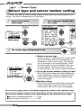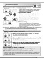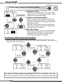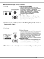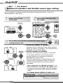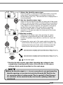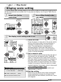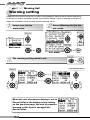
1
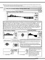
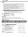
A’PEX SUPER AIRFLOW CONVERTER
SUPER
AIRFLOW CONVERTER
INSTRUCTION MANUAL
Thank you for purchasing the A’PEX
Super Airflow Converter. Please read
through this Instruction Manual to
operate this product correctly and keep
it near the product so that you may
refer to it whenever necessary.
If you transfer the product to another
customer, be sure to attach this
Instruction Manual and the warranty to
the product.
Product name
Product code
Applicable car models
Application
SUPER
AIRFLOW CONVERTER
SUPER AFCⅡ
401-A911 / 401-A913
Car models mentioned in the wiring diagram by model
Airflow / pressure sensor signal adjustment
A’PEX Chasing Our Dreams - A complete line of customized car and
automotive parts developed with state of the art technology and new
ideas. Our company is A'PEX which means the highest in quality.
A’PEX CO., LTD
1
Contents
Chapter 1 Introduction
Safety Precautions _____________________________________________________________________ 4
Features of this Product _______________________________________________________________ 6
Names and Functions of Parts ________________________________________________________ 8
Parts list ............................................................................................................... 8
Names of parts .................................................................................................... 9
Meanings of operation symbols appearing in this document ................................. 9
Chapter 2 Initial Setup
Procedure before Using This Product ________________________________________________ 12
Perform initial setup ___________________________________________________________________ 13
Setting the sensor type and sensor number 【Sensor Type】 ............................... 13
Setting the number of cylinders 【Car Select】 ...................................................... 13
Checking the throttle sensor voltage【Sensor chk】............................................... 13
Setting the throttle sensor type 【Car Select】 ....................................................... 13
Learning the throttle opening .............................................................................. 13
Correcting the knocking signal 【Knk Set】............................................................ 13
Chapter 3 Outline of Operating Method
Outline of Functions and Operating Method ___________________________________________ 16
Functions and Operations in monitor mode ___________________________________________ 18
Functions and Operations in the setting mode ________________________________________ 19
Functions and Operations in the etc, mod _____________________________________________ 19
Chapter 4 Monitor Mode 【Monitor Menu】
Channel Select 【1Channel】∼【4Channel】 ____________________________________________ 22
A plot display is made by using the RPM for the axis. 【Rev.-[Y]】 ______________________ 27
Chapter 5 Setting Mode 【Setting Menu】
Air correction factor setting (Throttle opening, large) 【Hi-Thrtl】 ________________________ 30
Air correction factor setting (Throttle opening, small) 【Lo-Thrtl】 _______________________ 30
Throttle opening setting 【TH-Point】 ___________________________________________________ 32
Air correction engine RPM setting 【Ne-Point】_________________________________________ 34
Deceleration air upper limit setting 【Dec.-Air】 _________________________________________ 36
Knocking signal correction 【Knk Set】 _________________________________________________ 38
Data file 【Data File】 _________________________________________________________________ 40
Chapter 6 Etceteras (etc.) Mode 【etc.Menu】
Sensor type and sensor number setting 【Sensor Type】 _______________________________ 44
Number-of-cylinders and throttle sensor type setting 【Car Select】 ____________________ 50
Sensor check 【Sensor chk】 _________________________________________________________ 52
Display scale setting 【Disp Scale】 ____________________________________________________ 53
Warning setting 【Waning Set】 ________________________________________________________ 54
Password setting and change 【Pass Lock】 ___________________________________________ 56
VFD brightness adjustment 【VFD Bright】 _____________________________________________ 58
Program version check 【Program Ver.】 _______________________________________________ 59
All data initialization 【Initialize】 ________________________________________________________ 60
Troubleshooting _______________________________________________________________________ 62
2
Chapter 1
Introduction
Safety Precautions ____________________________________ 4
Features of this Product ____________________________ 6
Names and Functions of Parts _____________________ 8
Parts list...........................................................8
Names of parts ................................................9
Meanings of operation symbols appearing in this
document ........................................................9
3
Safety Precautions
■Explanation of indications
Indication
Please read “Safety Precautions” carefully to operate
the product with safety.
Keep the Instruction Manual
in hand and refer to it
whenever needed.
The Instruction Manual
describes the items that you
must observe to operate the
product without giving any
injury to you, other people
and damage to property.
The meanings of pictorial
indications (signal words)
are as shown on right.
Please understand their
contents correctly before
starting to read the text.
Meaning
! WARNING
This indicates the existence of
potential hazard that will result
in death or serious injury of the
operator or a third person if the
product is wrongly operated in
disregard of this indication.
! CAUTION
This indicates the existence of
potential hazard that will result in
slight injury or medium damage to
the operator or a third person, and
that will result in only physical
damage if the product is wrongly
operated in disregard of this
indication.
REQUEST
This indicates the contents of a
failure in obtaining the full
performance of the product, or a
product failure or faulty function
item if the product is wrongly
operated in disregard of this
indication.
! WARNING
●Do not use this product for any application other than applicable
vehicles or applicable goods .
We shall disclaim the responsibility for operations in an application other than the
applicable vehicles or applicable goods. It will result in an unexpected accident.
●If this product gives out any abnormal noise or offensive smell, stop
operating the product immediately.
Using the product in this status will result in an electric shock, fire, or damage of
electric parts. Consult the distributor or your nearest business office for information.
●Do not use this product and its accessories in any way other than
specified by A’PEX.
In this case, we shall disclaim all responsibility for any damage or loss to the customer
and third persons.
●Do not turn on and/or off immediately during and after operating the key
Set/recorded data may be lost.
4
! WARNING
●The driver must not operate this product during driving
This may interfere with driving operations, resulting in an accident.
●Mount this product securely. Do not install it in an unstable place
that may interfere with driving
This may interfere with driving, resulting in an accident.
●When installing the product, remove the negative terminal of the
battery beforehand
A fire may be caused by short circuit or electric parts may be damaged or burnt out.
●When removing a coupler, be sure to hold the coupler without pulling
the harness
If the harness is pulled, a fire may be caused by short circuit or electric parts may be
damaged or burnt out.
●Be sure to perform wiring in accordance with the contents described
in the Instruction Manual
Incorrect wiring will result in a fire or other accidents.
●If any adjustment must be made during actual driving, take special
care not to interfere with other traffic, observing the traffic laws and
regulations
It will interfere with driving, resulting in an accident.
! CAUTION
●Regarding the installation of this product, be sure that it is installed
by an experienced professional
Installing the product requires technical knowledge and skill. Be sure that the installer
installs the unit securely.
●Do not tamper, disassemble, or modify this product
This may cause an accident, fire, electric shock, or electric parts will be damaged or
burnt out.
●Do not drop this product or expose it to strong shock
This may cause a malfunction, thereby giving damage to the product and the vehicle.
●Do not operate this product under direct sunlight or in high-temperature
vehicle interiors that are not air-conditioned in the summer season
A malfunction will be caused, thereby giving damage to the product and the vehicle.
●Do not install the product in a high-temperature place or in a place
exposed to direct water
It will cause an electric shock or fire, or electric parts will be damaged. The malfunction
may damage the vehicle.
5
Features of this product
The SUPER AFC II is a fuel adjustment controller in which the airflow sensor signal or the
pressure sensor signal can be modified in a 12 point RPM range by 1% increments to
increase/decrease fuel in a range of +50% to –50%. The RPM to be corrected can be
optionally set in 200 RPM increments, and corrections can be made according to throttle
opening amounts. In a turbo equipped vehicle with a hot wire type airflow meter, this
controller provides a preventive function for engine stall due to blow-back during throttle
return. The controller, which includes a knocking meter, allows the monitoring of knock
levels check keeping the engine under its optimum condition at all times. (Vehicle must
have a factory knock sensor)
■Unconventional large screen monitor using a high-brightness VFD
The futuristic front face of this unit uses the large screen, high-brightness and easy to
read VFD (Vacuum Fluorescent Display)
Use of the dot-matrix large screen monitor allows the displaying several types of
information simultaneously. Display variations are not limited to only numeric value
display, but also graph display, analog display, and other various displays are shown.
This allows the driver to recognize important information in an instant.
■Utilizes a thin case and single button
A thin case of 52 mm(L) x 126 mm(W) x 18 mm (D) (Minimum) has been achieved by
optimization of the circuit board and case design. The product can be easily installed
on the steering column or dash board. Since there is no separate unit besides the
main unit, it is not necessary to secure a place for installing any separate unit. Using a
4-direction switch with a center pushbutton and a rotary switch gets rid of the buttonto-button distance and permits quick operations, thereby providing efficient operation
of the unit.
■Battery-less memory that can keep initial setup data in the memory
even if the vehicle battery is disconnected
With the use of the EEPROM, the initial setup data is not lost unless initialization is
performed, even if the power supply is turned off or the vehicle battery is
disconnected. The setting data, such as peak value and correction value, is never
lost. Accordingly, if the vehicle battery is disconnected for service inspection, initial
setup and settings do not need to be performed again and the data history is not lost.
! CAUTION
●This product cannot be used for any application other than the
vehicles mentioned in the separate Vehicle Specific Application
Charts.
●Note that noise interference may be caused to radio, TV, etc.
depending on the mounting location of this product and the routing
of the signal harness.
●This product generates heat in the power ON status. This is not
abnormal.
6
■Storing two patterns of setting data in the memory
Two patterns of setting data including air correction factor, throttle opening, air
correction engine revolution speed, deceleration air upper limit, etc, can be stored
in the memory. There are two files that can be stored in the memory. The setting data
can be selected in an instant according to each driving stage such as circuit driving,
town driving, and winding driving. When driving on the same stage, two patterns of
setting data can be compared. These patterns of setting data can be used for various
purpose.
■Setting disable function by password
If the setting data or initial set points are changed by disoperation or mischief, the car
condition may be deteriorated, or in the worst case, the engine may be damaged. In
the SAFC II, when the user sets a password optionally, changing the setting data or
initial setup items is disabled.
■Warning function to make hazard known
It is possible to set warning values for the airflow using ratio, suction tube pressure,
Karman swirl sensor frequency, knocking, and engine revolution speed.
When each item is set, the car condition can be precisely judged. The setting for the
engine speed can also be used as a shift timing point.
◆Knocking
Spontaneous ignition is caused by the heat and pressure of mixed air in the burning
portion of non-combustion gas which is far from the plug and the heat of combustion
chamber wall, so that the gas in the whole combustion chamber generates highpressure waves momentarily. In this phenomenon, strong metallic noise is output from
the engine unlike car knocking by which the car body becomes jerky, with the result
that the valve is damaged and the piston is seized, thereby giving fatal damage to the
engine.
As countermeasures, fuel adjustment, ignition timing adjustment, compression ratio
adjustment, improvement of intake-side squish area, use of mirror type combustion
room wall, and profile improvement of the exhaust-side cam shaft can be mentioned.
! WARNING
●During driving, the driver must not operate this product in any case.
It will interfere with driving operations or result in an accident.
●On general public roads, observe the road and traffic law to drive
the car carefully.
7
Names and Functions of Parts
■Parts list
Before installing this product, be sure to check the parts list to confirm that there are not
any foreign or missing parts. If any difference is found between the actual parts and the
parts list, please contact the dealer of purchase.
2.Instruction manual(Operation part)
1.Main unit
3.Wiring diagram by model
4.Operation transition diagram
1volume
1sheet
SUPER
AIRFLOW CONVERTER
1unit 1volume (this document)
5.Warranty
6.Signal harness
1sheet
9.Plug
1sheet
10.Male sleeve
4pieces
13.Mounting stay
1pieces
8
4pieces
7.Splitting harness
1piece
11.Plug receptacle
4pieces
8.Splice
6pieces
12.Female sleeve
4pieces
■Names of parts
Optical sensor
(CDS sensor)
VFD display section
SUPER
AIRFLOW CONVERTER
4-direction switch with
a center pushbutton
Rotary switch
■Meanings of operation symbols appearing in this document
※Press the upper part of the center
switch
※Press the lower part of the
center switch
※Press the left part of the center
switch
※Press the right part of the
center switch
※Press the center pushbutton
※Turn the rotary switch counterclockwise or clockwise
When the rotary switch is turned clockwise, the numeric value shifts in the
positive direction or the cursor moves upward.
When the rotary switch is turned counterclockwise, the numeric value shifts in
the negative direction and the cursor moves downward. The upper/lower part
of the center switch has the same function as the rotary switch.
●Popup menu
When you press the center pushbutton, the popup menu shown at
right appears. The selected portion will appear as a reverse
display. Make a selection by the upper/lower/left/right part of the
center switch and decide the selection by pushing the center push
button.
Example)
Nx
Press the center pushbutton and select [Nx]
in the popup menu.
The meanings of alphabetic characters are as follows;
Tp[TOP] ......... Go back to the main menu
Nx[NEXT] ........ Go to the next
Pr[PREVIOUS] ... Go back to the previous
Cn[CANCEL] ..... Cancel the popup menu
9
10
第2章
Chapter 2
Initial Setup
Procedure before Using This Product _____ 12
Perform initial setup ___________________ 13
Setting the sensor type and sensor number 13
Setting the number of cylinders ................... 13
Checking the throttle sensor voltage ............ 13
Setting the throttle sensor type .................... 13
Learning the throttle opening ....................... 13
Correcting the knocking signal ..................... 13
11
Procedure before Using This Product
Install this product
The details of the installation procedure are described in the separate “Vehicle Specific Wiring
Diagram.” Install the product securely referring to the “Vehicle Specific Wiring Diagram” in a
separate document.
Turn on the ignition switch
Make sure that any abnormal noise or offensive smell is not produced from the SAFC II and the
Vehicle.
Perform initial setup
Perform initial setup securely by referring to page 13.
Turn the ignition switch off
The setting data is stored in the memory.
Start the engine
! CAUTION
●If no display appears, or any abnormal noise or offensive smell is
produced from this product despite proper installation, discontinue
operation of the product immediately and contact the dealer of
purchase.
12
Perform initial setup
To operate this product, you must set several items during initial setup.
After making sure that the SAFC II is securely installed, turn on the ignition switch and
select the ETC. (etc. mode) in the main menu.
Table of initial setup items
1.Setting the sensor type and sensor number (P.44 [Sensor Type])
Select Sensor Type and set the sensor type and sensor number
For vehicles equipped with a hot wire sensor, set the sensor output calculation
method.
2.Setting the number of cylinders (P.50 [Car Select])
Select Sensor Type and set the number of cylinders.
You can select it in the range of 1 to 16 cylinders.
Rotary engine car: Number of rotors ×2
Toyota V8 engine car: 4
Nissan Fairlady Z (Z33) Skyline (CPV35): 1
Mazda Atenza (GG#S/P, GY#W): 2
※For a car without throttle sensor signal, start operations from 6.
3.Checking the throttle sensor voltage (P.52 [Sensor chk])
Select Sensor chk and check the throttle sensor voltage with the throttle fully closed
and once with the throttle fully open.
4.Setting the throttle sensor type (P.50 [Car Select])
Select Car Select. When the throttle sensor voltage is 0 V to 1 V fully closed in the
previous step, set the arrow to the upward direction. When the throttle voltage is 3 V
to 5 V, set the arrow to the downward direction. When the arrow is set to the ※※
mark, no correction is performed by throttle opening.
5.Self learning the throttle opening
Self learn the throttle opening. Hold the throttle fully closed for about 10 seconds.
After that, hold the throttle fully open for about 10 seconds.
6.Turn off the ignition switch
When the ignition switch is turned off, the set items are stored in the memory
※After this, the initial setup is completed for a car without any knocking signal. For,
a car with a knocking signal, perform setting 7.
7.Correcting the knocking signal (P.38 [Knk Set])
Start the engine and perform warming-up. After completion of warming-up, select
Setting (setting mode) in the SAFC II main menu and select the knocking signal
correction mode. Correct the knocking signal.
With this, the initial setup is completed.
! WARNING
● Do not start the engine before starting the initial setup
If the engine is started without initial setup, the engine may be damaged.
13
14
Chapter 3
Outline of Operating Method
Outline of Functions and Operating Method ____16
What to be performed in the monitor mode _____18
What to be performed in the setting mode ______19
What to be performed in the etc. mode _________19
15
Outline of Functions
and Operating Method
Main menu
Monitor mode
The data obtained from the sensor is
displayed
The airflow usage
ratio, intake pressure, Karman
sensor frequency,
throttle opening,
engine RPM, air
correction factor,
knocking level, and
battery voltage are
displayed.
The SAFCⅡ consists
mainly of 3 menus;
Setting mode
This mode is used for the user to perform
settings
The air correction
factor, throttle open
ing, air correction,
engine RPM, and
the upper limit for
deceleration air is
set. Knocking
signal correction
and data file are
also controlled.
etc. mode
This mode is used to perform various
settings including initial setup
The initial setup,
display scale
setting, and
warning settings
are set according
to the vehicle
specifications, and
the pass word
setting/change,
VFD brightness
adjustment, and
initialization are
Performed.
16
■[Channel 1 to Channel 4] display items
1. Afl ........................Airflow (Hot wire/Flap) usage ratio
2. Prs ..................... Intake pressure
3. Kar.......................Karman sensor frequency
4. Thr ..................... Throttle opening
5. Rev .................... Engine RPM
6. Cor ..................... Air correction factor
7. Knk .................... Knocking level
8. Bat ..................... Battery voltage
■Rev. - [Y] display item
A plot display is made by using the engine RPM for the axis
■Setup items
1. Hi-Thrtl ................Air correction factor setting (throttle opening, large)
2. Lo-Thrtl .............. Air correction factor setting (throttle opening, small)
3. TH-Point............. Throttle opening setting
4. Ne-Point ............. Air correction engine RPM setting
5. Dec.-Air.............. Deceleration Air upper limit setting
6. Knk Set................Knocking signal correction
7. Data File ............ Data file control
■Setup items
1. Sensor Type....... Sensor type and sensor number setting
2. Car Select ...........Number-of-cylinders and throttle type setting
3. Sensor chk ..........Sensor check
4. Disp Scale.......... Display scale setting
5. Warning Set ....... Warning output setting
6. Pass Lock............Password setting/change
7. VFD Bright ......... VFD brightness adjustment
8. Program Ver....... Program version check
9. Initialize.............. All data initialization
17
Main menu 【Monitor】
Functions and Operations in the monitor mode
【One of items 1 to 4 is selected and displayed】
P22.【Monitor】→【1Channel】∼【4Channel】
[Contents of items]
1. Afl ..................Airflow (Hot wire/Flap) usage ratio
2. Prs................ Intake pressure
3. Kar ............... Karman sensor frequency
4. Thr................ Throttle opening
5. Rev............... Engine RPM
6. Cor ............... Air correction factor
7. Knk............... Knocking level
8. Bat .................Battery voltage
[Display method]
Numeric display/analog display : Real-time display, peak hold display, and pause.
Graphic display : Real-time display, replay, and pause.
Digital/analog display : Real-time display, peak hold display.
NOTE
●Regarding the 3 items Afl, Prs, and Kar, the contents that can be
displayed depend on the intake air volume measuring equipment of
the vehicle. For example, in the case of a car equipped with a hot
wire type airflow sensor, Afl can be displayed but Prs is not displayed.
【A plot display is made by using the engine RPM for the axis】
P27.【Monitor】→【Rev.-[Y]】
[Contents of the axis] One of the 5 items is selected and displayed.
1. Air Flow ......... Airflow (Hot wire/Flap) usage ratio
2. Pressure .......Intake pressure
3. Karman .........Karman sensor frequency
4. Throttle..........Throttle opening
5. Correct ..........Air correction factor
[Display method]
1-point display, 10-point display, and locus display
..................... Real-time display, replay, and pause.
18
Main menu 【Setting】
Functions and Operations in the setting mode
1. Hi-Thrtl .................................................................................................... P30
Air correction factor setting (throttle opening, large)
2. Lo-Thrtl .................................................................................................... P30
Air correction factor setting (throttle opening, small)
3. TH-Point .................................................................................................. P32
Throttle opening setting
4. Ne-Point .................................................................................................. P34
Air correction engine revolution speed setting
5. Dec-Air..................................................................................................... P36
Reduction gear upper limit setting (for the hot wire car only)
6. Knk Set .................................................................................................. P38
Knocking signal correction
7. Data File ................................................................................................ P40
Data file control
Main menu 【etc.】
Functions and Operations in the etc. mode
1. Sensor Type........................................................................................... P44
Sensor type and sensor number setting
2. Car Select .............................................................................................. P50
Number-of-cylinders and throttle sensor type setting
3. Sensor chk............................................................................................. P52
Sensor check
4. Disp Scale .............................................................................................. P53
Display scale setting
5. Warning Set ........................................................................................... P54
Warning setting
6. Pass Lock............................................................................................... P56
Password setting/change
7. VFD Bright.............................................................................................. P58
VFD brightness adjustment
8. Program Ver. .....................................................................................P59
Program version check
9. Initialize.................................................................................................. P60
All data initialization
19
20
Chapter 4
Monitor Mode
One of items 1 to 4 is selected and
displayed _________________________22
A plot display is made by using the RPM
for the axis
______________________27
21
【Monitor Menu】→【1Channel】∼【4Channel】
Channel Select
Of the following 8 items, one of channels 1 to 4 is selected and displayed. A numeric display,
analog display, graphic display, and digital/analog display are available as the display
method. A pause is also available in each display (except the digital/analog display). In the
numeric display, analog display and digital display, peak hold can be performed. In the
graphic display, replay (*) can be performed.
■Contents of display items
[Note]The replay function stores the last saved display in the memory. Accordingly,
even if the display item is changed, the last saved item display is replayed.
regardless of the display item.
1. Afl ........ Airflow usage ratio 2. Prs....... Intake pressure
4. Thr.......Throttle opening 5. Rev...... Engine RPM
8. Bat....... Battery voltage
7. Knk ......Knocking level
3. Kar ...... Karman sensor
6. Cor.......Air correction factor
●Numeric display example
【Function】Pause and peak hold
1-channel display
2-channel display
3-channel display
4-channel display
●Analog display example ●Digital/analog display ●Graphic display
example [Function] Peak hold 【Function】 Pause and replay
【Function】 Pause and peak hold
1-channel display
1.
2-channel display
Select [Monitor] in the main
menu
Common display to all channels
1-channel display
Go back
2.
Select [1 to 4
Channel] in the
monitor menu
or
Pr
1-item data display
2-item data display
3-item data display
Main menu
Select
Monitor menu
Enter
Select
or
22
4-item data display
Enter
or
Nx
=
3.
※When the upper part of the center switch is pressed, the
operation is the same as when the rotary switch is turned
clockwise. When the lower part of the center switch is pressed,
the operation is the same as when the rotary switch is turned
Counterclockwise.
Go back
Select the data to be display in the item
selection menu
or
Pr
■When selecting [1 Channel]
(1) Select a display item
Operate the upper part or lower part of the
switch in the display item selection mode
to select a display item. The selected item
is displayed as a reversing display.
(2) Make a display
Press the right part of the switch or press
the center pushbutton to make a display.
Select
Display item selection
Enter
or
Nx
■When selecting [2 to 4 Channel]
(1) Select a display channel
Operate the upper part or lower part of
the switch in the display channel selection mode to select a display channel.
Select
The number of the selected channel is
displayed as a reserving display.
(2) Select a display item
Select a display channel and operate the
Display channel selection
right part of the switch to set the display
item selection mode. The numeric value
of channel and the display item are
displayed as a reversing display. In this
status, operate the upper part or lower
part of the switch to select a display item.
(3) Select a display item of another
Select
Enter
channel
Operate the left part of the switch in the
display item selection mode to go back to
the display channel selection mode.
or
Display item selection
Repeat steps (1) and (2) until all the
display items are set.
Nx
(4) Make a display
Operate the right part of the switch in the
display item selection mode, or press the
The above display screen example is
center pushbutton in the display channel
displayed when the sensor type is a hot wire
selection mode and select [Nx] in the
type or a flap type and [2 Channel] is selected. popup menu to make a display.
23
※Hold down the lower part of the center switch to display the air correction
factor (P30) setting screen. Hold down the lower part of the center switch
on the air correction factor setting screen to go back to the monitor display.
4.
Go back
The selected item is displayed in the item
selection menu
Each time the center
push button is pressed
Nx
and [Nx] is pressed in the
popup menu, (numeric
Digital/analog display
display) → (graphic
Nx
display) → (analog display)
→ (digital/analog display)
→ (numeric display) … is
selected in sequence.
Pr
Numeric display
Nx
Nx
Graphic display
Analog display
●Function at numeric display and analog display
For the analog
display, up to 2
items are
displayed. When
[3 Channel] or
more is selected,
selection No.1
and 2 are
displayed
●Ordinary display
Pause
Peak
■Pause
The item is
displayed
as a reversing
display
Reset
■Peak value reset setting
■Peak display
Select an item to be reset and enter it
Reset
Reset
setting
Select
Reset
res.
1.
2.
3.
4.
5.
6.
7.
Afl
Prs
Kar
Thr
Rev
Knk
A l l
Contents of the menu
←Airflow usage ratio
←Intake pressure
←Karman sensor
←Throttle opening
←Engine RPM
←Knocking
←All items
Go back without resetting
Peak value
※The figure shows an example when[1 Channel] is selected
24
or
※The following figure shows an example
when [1 Channel] is selected.
●Function at graphic display
■Replay function
Restart
●Ordinary display
Temporary stop
Replay start
(Rightward scroll)
Rightward scroll
Reset
Memory start
Leftward scroll
Pause
Rightward scroll
Restart
Temporary stop
■Memory function
Leftward scroll
Memory stop
■Pause
Remaining time
Reset
The memory time is
as follows
【1Channel】 ...... 60sec
【2Channel】 ...... 30sec
【3Channel】 ...... 20sec
【4Channel】 ...... 15sec
NOTE
●Regarding the 3 items Afl, Prs, and Kar, the contents that can be
displayed depend on the intake air volume measuring equipment of
the vehicle. For example, in the case of a car provided with a hot
wire type airflow sensor, Afl can be displayed but Prs cannot be
displayed.
25
●Function in the digital/analog display
※In the digital/analog display, a 4 channel display is made regardless of
the selected channel. The display items are fixed to the 4 items: engine
RPM, throttle opening, knocking level, and air correction factor.
●Ordinary display
■Peak display
Peak
Reset
Peak value
■The numeric display blinks?!
Check if warning function is set
When Rev [engine RPM], Knk [Knocking level], or other parameter is displayed,
the numeric value blinks as a reversing display after it exceeds the set the RPM
or the preset level. (P.54)
■The numeric display or analog display cannot be moved?!
Check if pause function is set
If Pause is set, the numeric display or analog display will not move. Operate the
lower part of the center switch to reset the pause status.
26
【Monitor Menu】→【Rev.-[Y]】
A plot display is made by using the RPM for the axis
1.
2.
Select [Monitor] in the
main menu
Select
Go back
Select [Rev. –[Y]] in
the monitor menu
or
Select
Enter
Pr
Enter
or
or
Main menu
Monitor menu
Nx
Go back
3.
Select the data to be
displayed in the item
selection menu
Select
or
4.
Pr
Enter
The selected item is
displayed in the item
selection menu
Go back
Pr
※Press the center pushbutton. Each time [Nx] is
pressed in the popup menu, (1-point display) →
(10-point display) → (Map trace display) → (1-point
display) is selected in sequence
or
1. Airflow .......Airflow usage ratio
2. Pressure ...Intake pressure
3. Karman .....Karman sensor frequency
4. Throttle......Throttle opening
5. Correct ......Air correction factor
■Memory function
Nx
Nx
1-point display
■Replay function
Replay
time
Remaining time
Memory time 30sec
Memory start
Replay start
Replay end
10-point display
Nx
Nx
Memory stop
Trace clear
Pause
The memory of [1 to 4
Channel] is cleared
After the memory
is replayed, the
replay is automatically
ended
Map trace display
27
28
Chapter 5
Setting Mode
Air correction factor setting (Throttle
opening, large) ___________________________________ 30
Air correction factor setting (Throttle
opening, small) ___________________________________ 30
Throttle opening setting ________________________ 32
Air correction engine RPM setting___________ 34
Deceleration air upper limit setting __________ 36
Knocking signal correction ____________________ 38
Data file ____________________________________________ 40
29
【Setting Menu】→【Hi-Thrtl】・【Lo-Thrtl】
Air correction factor setting (Throttle opening, large / small)
In the SAFCⅡ, the input airflow signal is converted into an air volume value and this
value is corrected by the air correction factor. As an output signal, the corrected air
volume value is converted back into an airflow signal and then this signal is output to
the electronic control unit (ECU).
Accordingly, supposing that the correction factor is +10%, the ECU recognizes that
the air volume has increased 10%, so fuel is increased about +10%
For air correction factor setting, the air correction factor can be adjusted by 1%
increments in the correction range of +50% to –50% for each engine RPM at 12 points.
It can also be set according to the throttle opening level.
Final number
Correction area (increase amount)
Correction engine RPM
Correction factor = zero
Correction factor
Correction area (Decrease amount)
1.
Throttle opening
The graph, at selection, is
displayed as a highlight display
Select [Setting] in the
main menu
2.
Select [Hi / Lo-Thrtl] in the
setting menu
Select
Go back
Select
or
Pr
Main menu
Enter
Setting menu
or
! WARNING
●Do not operate this product while driving
It will interfere with driving operations, resulting in an accident.
30
Enter
or
Nx
※When the upper part of the center switch is held down on the air correction factor setting screen, the set
correction value is put into the flat (correction) status.
The set value is returned to the initial status by holding down the upper part of the same switch once again.
3.
The air correction factor setting mode is set
Go back
Pr
Ordinary display image diagram
The ordinary display setting screen is as shown in the above image diagram. The actual
display is shown in the lower left figure. The screen is scrolled by pressing the left or
right part of the center switch. If either the upper part or the lower part of the center
switch is pressed during the ordinary display, this display is changed into a reduced
display as shown in the lower right figure. In this case, all setting graphs are displayed
on a single screen. The reduced display can be changed into the ordinary display by
pressing either the upper part or the lower part of the center switch.
Reduced display
Actual ordinary display
Display changeover
RPM selection
Correction factor
increase/decrease
Like the ordinary display and reduced display, the engine
RPM is selected by the left or right part of the center switch,
and the correction factor is increased or decreased by the
rotary switch.
When the rotary switch is turned clockwise, the graph is
shifted in the positive direction (increase). When the rotary
switch is turned counterclockwise, the graph is shifted in the
negative direction (decrease).
Nx
【Hi-Thrtl】
【Lo-Thrtl】
Each time [Nx] is pressed in
the popup menu
after the center pushbutton
is pressed, the Hi-Thrtl
mode and the Lo-Thrtl
mode can be switched
over to each other.
31
【Setting Menu】→【TH-Point】
Throttle opening setting
1.
Select [Setting] in the
main menu
2.
Select [TH-Point] in the
setting menu
Select
Select
Go back
or
Pr
Main menu
Enter
Setting menu
or
3.
The throttle opening setting mode is set
Select
■Setting range
Nx
or
Go back
or
Pr
(1) Select the throttle opening Lo/Hi
Operate the left/right part of the center switch
to select the throttle opening Lo or Hi. The
Increase/decrease selected numeric value is displayed as a
reversing display.
(2) Select a numeric value
Select a numeric value and press the upper or
lower part of the center switch or turn the
or
rotary switch counterclockwise or clockwise to
increase or decrease the numeric value.
When the rotary switch is turned clockwise,
the numeric value is increased. When this
switch is turned counterclockwise, the numeric
value is decreased.
(3) End the setting
Select [Pr] in the popup menu after pressing
the center pushbutton or press the left part of
the center switch at throttle opening Lo
selection and the setting menu will reappear.
The value in parentheses is the initial value
Lo【Throttle opening, small】
0∼98 (10) [%]
Hi【Throttle opening, large】 1∼99 (50) [%]
※Settable by 1% increments
32
Enter
Correction factor change due to throttle opening setting.
When the throttle opening is set to Lo-10% and Hi-50%, the air correction factor at a
throttle opening of 40% is as follows;
● At a throttle opening of 50% or more, the air correction factor is equal to
“Correction factor set at Hi-Thrt +3%”
● At a throttle opening of 10% or less, the air correction factor is equal to
“Correction factor set at Lo-Thrt -1%”
Air correction factor at a throttle opening of 40%
Correction value
+3%
0.25
+2%
0.75
-1%
0
20%
40%
60%
Throttle opening
※The air correction factor at a throttle opening of 40% can be obtained by the following formula;
(3%-(-1%))×(40%-10%)
50%-10%
+(-1%)=2%
33
【Setting Menu】→【Ne-Point】
Air correction engine RPM setting
1.
Select [Setting] in the
main menu
2.
Select [Ne-Point] in the
setting menu
Select
Go back
Select
or
Pr
Main menu
Enter
Setting menu
Enter
3.
Nx
or
or
Go back
The air correction engine RPM setting mode is set
Select
or
Pr
Increase/decrease
or
or
Engine revolution speed selection
Engine revolution speed setting
Ne : Engine RPM
Ne01<Ne02<Ne03<Ne04<Ne05<Ne06<Ne07<Ne08<Ne09<Ne10<Ne11<Ne12
For Ne02, the engine revolution speed cannot be set to a lower value than that of
Ne01. The same can be said for the other revolution points,
■Setting range
The value in parentheses is the initial value
Ne Point【Engine revolution point】800∼9800 [rpm]
(1000.1600.2200.2800.3400.4000.4600.5200.5800.6400.7000.7600)
※Settable by 200 rpm steps
34
(1) Select an engine RPM point
Press the upper or lower part of the center switch or turn the rotary switch counterclockwise or clockwise to select an engine RPM point. The selected item is displayed
as a reversing display. When the rotary switch is turned clockwise, the cursor is moved
upward. When this switch is turned counterclockwise, the cursor is moved downward.
(2) Set the engine RPM
Select an engine revolution point and press the right part of the center switch to set the
engine RPM. When the upper or lower part of the center switch is pressed or the rotary
switch is turned counterclockwise or clockwise, the numeric value is increased or
decreased.
When the rotary switch is turned clockwise, the numeric value is increased. When this
switch is turned clockwise, the numeric value is decreased.
⇒ For setting another engine RPM point
Operate the left par of the center switch and repeat steps (1) and (2).
(3) End the setting
Select [Pr] in the popup menu after pressing the center pushbutton or press the left part
of the center switch at engine RPM point selection (No.01 to No.12), and the setting
menu will reappear.
How to make a correction by engine RPM setting and throttle opening setting.
※Setting
example
Thr
Ne
Ne01
Ne02
Ne03
Ne04
Ne05
Ne06
Ne07
Ne08
Ne09
Ne10
Ne11
Ne12
1000
1600
2200
2800
3400
4000
4600
5200
5800
6400
7000
7600
(Hi)
80%
Hi
2
4
3
3
6
8
9
9
7
5
3
1
(Lo)
30%
Lo
-4
-2
0
1
2
2
1
0
-1
-2
-3
-3
Engine revolution speed (rpm)
1000
1600
2200
2800
3400
4000
4600
5200
5800
6400
7000
7600
0
-4
-2
0
1
2
2
1
0
-1
-2
-3
-3
10
-4
-2
0
1
2
2
1
0
-1
-2
-3
-3
20
-4
-2
0
1
2
2
1
0
-1
-2
-3
-3
Accelerator opening(%)
30
-4
-2
0
1
2
2
1
0
-1
-2
-3
-3
40
-2.8
-0.8
0.6
1.4
2.8
3.2
2.6
1.8
0.6
-0.6
-1.8
-2.2
50
-1.6
0.4
1.2
1.8
3.6
4.4
4.2
3.6
2.2
0.8
-0.6
-1.4
60
-0.4
1.6
1.8
2.2
4.4
5.6
5.8
5.4
3.8
2.2
0.6
-0.6
70
0.8
2.8
2.4
2.6
5.2
6.8
7.4
7.2
5.4
3.6
1.8
0.2
80
2
4
3
3
6
8
9
9
7
5
3
1
90
2
4
3
3
6
8
9
9
7
5
3
1
100
2
4
3
3
6
8
9
9
7
5
3
1
At an opening
below Lo-Thrtl,
the same correction
factor is applied.
At an opening
between Hi-Thrtl
and Lo-Thrtl, linear
interpolation is
applied.
At an opening
over Hi-Thrtl, the
same correction
factor is applied.
35
【Setting Menu】→【Dec.-Air】
Deceleration air upper limit setting
In the case of a turbo vehicle equipped with a hot wire type airflow sensor, the engine may
be stalled by blow-back when the throttle is released.
In this case, engine stall can be prevented by using the deceleration air upper limit setting.
With the deceleration air upper limit setting, an upper limit is given to the airflow output
voltage at the engine RPM set at Ne01 and Ne02 (Ne01 and Ne02 of Ne-Point) below the
“Thr” throttle opening.
1.
Select [Setting] in the
main menu
Main menu
2.
Select [Dec.-Air] in the
setting menu
Select
Select
Enter
Enter
or
3.
Go back
Setting menu
or
Pr
or
Nx
Go back
The deceleration air upper limit setting mode is set
or
Pr
Select
Increase/decrease
or
or
NOTE
●At an engine RPM over Ne02, deceleration air
upper limit setting is not active.
●When Thr is ****, deceleration air upper
limit setting is not active.
36
(1) Select a throttle opening and an engine RPM
Press the upper or lower part of the center switch or turn the rotary switch counterclockwise or clockwise to select an engine RPM point. The selected item is displayed
as a reversing display. When the rotary switch is turned clockwise, the cursor is
moved upward. When this switch is turned counterclockwise, the cursor is moved
downward.
(2) Set a numeric value
Select each item and press the right part of the center switch. The throttle opening can
be set by Thr and the upper limit of airflow usage ratio can be set by Ne01 and Ne02.
When the upper or lower part of the center switch is pressed, or the rotary switch is
turned counterclockwise or clockwise, the numeric value is increased or decreased.
When the rotary switch is turned clockwise, the numeric value is increased.
When this switch is turned counterclockwise, the numeric value is decreased.
(3) End the setting
Select [Pr] in the popup menu after pressing the center pushbutton or press the left
part of the center switch at item selection (Thr, No.01 and No.02), and the setting
menu will reappear.
Setting Dec.-Air
1. Ne01 / Ne02 RPM check
Turn on the ignition switch, and check the Ne01/Ne02 RPM at air correction point
setting [Ne-Point]. The initial value is 1000 rpm for Ne01 and 1600 rpm for Ne02.
2. Thr / Afl / Rev check
In the monitor mode [Monitor], make a selection so that the throttle opening (Thr),
engine RPM (Rev), and airflow usage ratio (Afl) may be displayed.
Start the engine and set the gear to the neutral position. Before the engine is warmed
up, perform the following operations.
1. Hold the engine RPM of Ne02 (initial value: 1600 rpm). At that time, check the
throttle opening and the airflow usage ratio.
2. Hold the engine RPM of Ne01 (initial value: 1000 rpm). At that time, check the
airflow usage ratio.
3. Input Dec-Air
Select Thr of the deceleration air upper
limit setting [Dec.-Air] and input a
smaller numeric value than the throttle
opening checked in 2-1). Next, select
Ne01 and input a larger numeric value
than the airflow using ratio checked in 2-2).
Lastly, select Ne02 and input a larger
numeric value than the airflow using
ratio checked in 2-1).
37
【Setting Menu】→【Knk Set】
Knocking signal correction
Setting is performed to convert a signal obtained from the knock sensor into a knocking
level. Corrections are made in the 2 point RPM area for slight knocking signal variation
due to different knocking sensor manufacturers, vehicle models, or due to an individual
difference within the same model.
This step is indispensable for initial setup.
※Note ・・・When setting this item, do not perform idling on a general public road.
1.
Select [Setting] in the
main menu
2.
Go back
Select [Knk Set] in the
setting menu
Select
Main menu
Setting menu
Enter
Nx
or
or
3.
Pr
Select
Enter
or
Go back
The knocking signal correction mode is set
or
Pr
(1) Select a correction revolution point
Press the upper or lower part of the center
switch or turn the rotary switch counterclockwise or clockwise to select a correction
RPM point. The selected item is displayed as
a reversing display. When the rotary switch is
turned clockwise, the cursor is moved upward.
When this switch is turned counterclockwise,
the cursor is moved downward.
(2) Perform signal correction
Select a correction RPM point and increase
the engine RPM to the specified RPM. Then,
press the right part of the center switch to
Correct
correct the knocking signal.
(3) End the setting
Select [Pr] in the popup menu after pressing
the center push button or press the left part of
Real-time RPM
the center switch, and the setting menu will
reappear.
Real-time knocking sensor raw data
(not a knocking level)
Select
or
38
Setting Knk Set
1. Correct RPM 1
2.
3.
(Example)
Hold the engine RPM at a fixed value between 1300
rpm and 1700 rpm in the no-load status (neutral).
(In the example shown on the right, it is held at 1600
rpm.) After the RPM becomes stable, press the right
part of the center switch. At completion of correction,
Increase the RPM
the data on RPM and knocking sensor is recorded.
to the specified
(In the example shown on the right, they are 1680 rpm
RPM area
and 27, respectively.) If correction fails, the RPM
remains 1500 rpm. Perform correction again in the
Correct
specified RPM area.
Correct RPM 2
In the same way as for the correction of RPM 1, hold
the engine RPM at a fixed value between 3200 rpm
After the RPM become
and 3700 rpm in the no-load status (neutral). (In the
s stable, press the
example shown on the right, it is held at 3300 rpm.)
right part of the center
After the RPM becomes stable, press the right part of
switch
the center switch. At completion of correction, the data
on RPM and knocking sensor is recorded. (In the
example shown on the right, they are 3390 rpm and
48, respectively.) If correction fails, the RPM remains
3500rpm. Perform correction again in the specified
Correct
RPM area.
After completion of correction
Select Knock (Knk) in the monitor mode and check that
the mark × disappears on the display. When this mark
As shown above, when
the RPM becomes
disappears, the correction is completed. If not, perform
stable in the specified
correction once again.
RPM area, press the
right part of the center
switch
NOTE
Check if the mark × disappears
●For a vehicle provided with a genuine knocking sensor signal, be sure to perform setting.
Without this setting, a knocking level value is not displayed in the monitor mode.
●For a vehicle without a genuine knocking sensor signal, this feature cannot be used.
●Due to the characteristics of factory knock sensors, a knocking level value may be
displayed as a lower value even in a situation where damage is being done to the
engine from knocking or improper combustion processes ! This is only to be used as a
reference.
39
【Setting Menu】→【Data File】
Data file
1.
Select [Setting] in the
main menu
2.
Select [Data File] in the
setting menu
Select
Go back
Select
or
Pr
Main menu
Enter
or
3.
Setting menu
Enter
Nx
or
Go back
The data file control mode is set
or
Select
or
Changeover
NOTE
●Both File 1 and File 2 cannot be turned on or off simultaneously.
When one of them is turned on, the other is turned off
40
Pr
(1) Select a data file
Press the upper or lower part of the center switch and turn the rotary switch
counterclockwise or clockwise to select a data file. The selected item is displayed as a
reversing display. When the rotary switch is turned clockwise, the cursor is moved
upward. When this switch is turned counterclockwise, the cursor is moved downward.
(2) Change over the data file between ON and OFF
Select each item and press the right part of the center switch. With this, it can be
selected whether the saved data is validated or not (ON/OFF). When the upper part
of the center switch is pressed, the saved data is validated (ON).
When the lower part of this switch is pressed, the saved data is invalidated (OFF).
(3) End the setting
Select [Pr] in the popup menu after pressing the center pushbutton or press the left
part of the center switch at item selection (File 1, File 2), and the setting menu will
reappear.
●Saving and loading setting data
The 4 items (air correction factor Hi/Lo setting, throttle
opening setting, air correction engine RPM setting, and
deceleration air upper limit setting) can be saved and
loaded in the data file.
If any setting is changed in these 4 items, the changed
setting is automatically saved in the file (file in the ON
status).
<Auto Save function >
In the initial status (at delivery from the factory), File 1 is set
to ON and File 2 is set to OFF.
When File 2 is turned on, File 1 is turned off. At this time,
the data saved in File 2 is loaded. When File 2 is tuned on
for the first time, the initial (factory-set) data is loaded.
If there is a history to indicate that the setting was
previously changed by turning on File 2, the changed data
is loaded at that time.
Because saving is performed by overwriting, the data to be
loaded is the immediately saved data.
When File 1 is turned on, the same can be said.
! WARNING
●Never change over a file during driving
There is a possibility that there may be a large difference in
specifications in some setting data causing severe engine
damage.
41
42
Chapter 6
Etceteras (etc.) Mode
Sensor type and sensor number setting __ 44
Number-of-cylinders and throttle sensor
type setting_________________________________________50
Sensor check ______________________________________52
Display scale setting_____________________________53
Warning setting ___________________________________54
Password setting and change_________________56
VFD brightness adjustment ____________________58
Program version check _________________________59
All data initialization______________________________60
What to do in such a case?____________________62
43
【etc.】→【Sensor Type】
Sensor type and sensor number setting
The sensor type and the sensor number (sensor characteristic) are set according to the
vehicle. This item is indispensable for initial setup.
1.
2.
Select [etc.] in the
main menu
Select [Sensor Type] in the
etc. menu
Go back
Select
Select
or
Pr
Main menu
Select
Decide
or
3.
or
Nx
etc. menu
Go back
The sensor type setting mode is set
or
Pr
(1) Select a sensor type
Select
or
Sensor selection
Press the upper or lower part of the center switch
and turn the rotary switch counterclockwise or
clockwise to select a sensor type. The selected
item is displayed as a reversing display. When
the rotary switch is turned clockwise, the cursor
is moved upward. When this switch is turned
counterclockwise, the cursor is moved downward.
(2) Go to the sensor number setting screen
Select [Nx] in the popup menu after pressing the
center pushbutton or press the right part of the
center switch, and the sensor number setting
screen will appear.
(3) End the setting
Select [Pr] in the popup menu after pressing the
center pushbutton or press the left part of the
center switch, and the etc. menu will reappear.
For the sensor types, refer to the Wiring diagram by model on the separate sheet.
The sensor number setting varies depending on the selected sensor type.
●Hot-Wire or Pressure selection ・・・・・・・P45
●Flap or Karman selection ・・・・・・・・・・・・P49
44
4.
Set the sensor number
Go back
or
Pr
●When the sensor type is set to Hot-Wire or Pressure
(1) Select In/Out
Operate the left or right part of the center switch to
Increase/
select In or Out. The selected numeric value is
decrease
displayed as a reversing display.
(2) Set the sensor number
Select a numeric value and press the upper or lower
part of the center switch or turn the rotary switch
counterclockwise or clockwise to increase or
Select
decrease the numeric value.
or
When the rotary switch is turned clockwise, the
numeric value is increased. When this switch is
turned counterclockwise, the numeric value is
decreased.
(3) End the setting
Select [Pr] in the popup menu after pressing the
center pushbutton or press the left part of the center
switch at In selection, and the sensor type setting
screen will reappear.
For the sensor numbers, refer to the Wiring diagram by model on the separate sheet.
For ordinary use, set the same sensor number between In and Out.
■Depending on the car specifications, the In setting and the Out setting must be changed even if the car model is the same.
(Example )
Silvia S14 SR20DET ‘93.10∼‘98.12
※When the ECU and the airflow sensor are Normal
In 05=S14 normal airflow sensor
Out 05=S14 normal airflow sensor
※When the ECU is Normal and the airflow sensor is for Z32
In 02=Z32 airflow sensor
Out 05=S14 normal airflow sensor
※When the ECU has the characteristics of an airflow
sensor for Z32 and the airflow sensor is for Z32
In 02=Z32 airflow sensor
Out 02=Z32 airflow sensor
●For Pressure, the setting is completed
After the setting of the above (3) is completed, exit from the setting screen.
At this time, the set numeric value is saved.
●For Hot-Wire, set the sensor output calculation method
Select [Nx] in the popup menu after pressing the center pushbutton or press the right
part of the center switch at Out selection, and the sensor output calculation method
setting screen will appear.
45
5.
Go back
Set the sensor output calculation method
Select
or
Pr
(1) Select In or Out
Operate the left or right part of the center switch
to select In or Out. The selected numeric value is
Changeover
displayed as a reversing display.
(2) Set the calculation method
Select a numeric value and press the upper or
lower part of the center switch or turn the rotary
switch counterclockwise or clockwise to select a
or
calculation method.
When the rotary switch is turned clockwise, the
operation is the same as when the upper part of
the center switch is pressed.
(3) End the setting
Select [Pr] in the popup menu after pressing the
center pushbutton or press the left part of the
center switch at In selection, and the sensor
number setting screen will reappear.
Calculation method operation diagram
※Pressing the upper part of the center switch provides the same function as turning the rotary
switch clockwise, and pressing the lower part of the center switch provides the same function as
turning the rotary counterclockwise.
At In selection
At out
selection
At out
selection
At In selection
For almost all the models except Skyline GT-R, In 1 and Out 1 are set.
For the setting method, refer to the setting examples shown on and after the next page.
46
Setting the sensor output calculation method (1)
●General vehicles (Usually, this setting is performed.)
When the product is used with an airflow sensor and an
ECU with single airflow sensor control.
※Because of a single engine control unit input
※Because of a single airflow sensor
In
1
Measured air volume
10
SUPER
AIRFLOW CONVERTER
Input air volume
10
Out
1
Output air volume
10
ECU
※In this case, the airflow sensor measures
an air volume of 10.
Airflow
sensor
Setting the sensor output calculation method (2)
●Skyline GT-R
When the product is used with two airflow sensors and an
ECU with twin airflow sensor control.
※Because of 2 airflow sensors
In
2
SUPER
AIRFLOW CONVERTER
Out
Ave
※Because of 2 engine control unit
inputs, the measured air volume of
the 2 airflow sensors is averaged
(Ave) and its result is output.
Measured air volume
4
Input air volume
10
Airflow
sensor 1
Measured air volume
6
Output air volume
5
ECU
Output air volume
5
Airflow
sensor 2 ※In this case, airflow sensor 1 measures
an air volume of 4 and airflow sensor 2
measures an air volume of 6.
47
Setting the sensor output calculation method (3)
●General vehicles using 2 airflow sensors
When the product is used with two airflow sensors and an
ECU with single airflow sensor control.
※Because of 2 airflow sensors
In
2
SUPER
AIRFLOW CONVERTER
Out
Add
※Because of a single engine control
unit input, the measured air
volume of the 2 airflow sensors is
added (Add) and its result is output.
Measured air volume
4
Input air volume
10
Airflow
sensor 1
Output air volume
10
ECU
Measured air volume
6
Airflow
sensor 2
※In this case, airflow sensor 1 measures an air
volume of 4 and airflow sensor 2 measures an
air volume of 6.
Setting the sensor output calculation method (4)
●Skyline GT-R using an airflow sensor
When the product is used with an airflow sensor and an
ECU with twin airflow sensor control.
※Because of a single airflow sensor
In
1
SUPER
AIRFLOW CONVERTER
Out
1/2
※Because of two engine control
unit inputs, the measured air
volume of the airflow sensor is
divided into halves and its result
is output.
Measured air volume
10
Input air volume
10
Airflow
sensor
48
※In
this case, the airflow
sensor measures an air
volume of 10.
Output air volume
5
ECU
Output air volume
5
●When the sensor type is Flap or Karman
1. For Flap
(1) Set the sensor number
Press the upper or lower part of the center
switch or turn the rotary switch counterclockwise
Increase/decrease
or clockwise to increase or decrease the
numeric value. When the rotary switch is turned
clockwise, the numeric value is increased.
When this switch is turned counterclockwise,
the numeric value is decreased.
(2) End the setting
or
Select [Pr] in the popup menu after pressing
the center pushbutton or press the left part of
the center switch at In selection, and the sensor
type setting screen will reappear.
※For the sensor numbers, refer to the Wiring diagram by model on
the separate sheet.
2. For Karman
Select
or
(1) Select Karman
Press the upper or lower part of the center switch
or turn the rotary switch counterclockwise or
clockwise to select Karman. The selected item is
displayed as a reversing display. When the rotary
switch is turned clockwise, the cursor is moved
upward. When this switch is turned
counterclockwise, the cursor is moved downward.
(2) End the setting
Select [Pr] in the popup menu after pressing the
center pushbutton or press the left part of the
center switch, and the etc. menu will reappear.
※When Karman is selected, sensor number setting is not required.
49
【etc.】→【Car Select】
Number-of-cylinders and throttle sensor type setting
Set the number of cylinders and the throttle type according the vehicle. This item is
indispensable for initial setup.
1.
2.
Select [etc.] in the
main menu
Select [Car Select] in the
etc. menu
Select
Select
Go back
or
Pr
Main menu
Decide
Decide
or
or
etc. menu
3.
Nx
Go back
The number-of-cylinders and throttle sensor type
setting mode is set
Select
Select
or
or
Pr
(1) Select the number of cylinders
Operate the left or right part of the center switch to
select the number of cylinders. The selected item is
displayed as a reversing display.
(2) Set the number of cylinders
Select an item and press the upper or lower part
of the center switch or turn the rotary switch
counterclockwise or clockwise to increase or
decrease the numeric value.
When the rotary switch is turned clockwise, the
numeric value is increased. When this switch is
turned counterclockwise, the numeric value is
decreased.
※For a rotary car, set “Number of rotors” × 2
※For a Toyota car mounting a V8 engine, set 4
※For Nissan Fairlady Z (Z33), Skyline (PCV35)
set 1
※For Mazda Atenza (GG#S/P, GY #W), set 2
■Setting range
C y l 【cylinders】
50
The value in parentheses is the initial value
1∼16 (6)
※ Settable by 1 cylinder steps
(3) Select the throttle sensor type
Press the upper or lower part of the center switch or turn the
rotary switch counterclockwise or clockwise to select the
throttle sensor type (Thr). The selected item is displayed as a
reversing display.
(4) Set the throttle sensor type
Select an item and press the upper or lower part of the center
switch or turn the rotary switch counterclockwise or clockwise
to change the direction of the arrow (sensor type). When the
rotary switch is turned clockwise, the operation is the same
as when the upper part of the center switch is pressed.
When the rotary switch is turned counterclockwise, the
operation is the same as when the lower part of the center
switch is pressed.
(5) End the setting
Select [Pr] in the popup menu after pressing the center
pushbutton or press the left part of the center switch at
number-of-cylinders (Cyl) selection, and the etc. menu will
reappear.
※Pressing the upper part of the center switch provides the
same function as turning the rotary switch clockwise, and
pressing the lower part of the center switch provides the
same function as turning the rotary counterclockwise.
When the throttle is completely closed, the throttle sensor voltage is 0 V to 1 V.
When the throttle is completely opened, the throttle sensor voltage is 3 V to 5 V.
Select
When the throttle is completely closed, the throttle sensor voltage is 3 V to 5 V.
When the throttle is completely opened, the throttle sensor voltage is 0 V to 1 V.
No throttle signal
※Set the throttle sensor type after checking the voltage in the
completely closed/opened status of the throttle in the sensor
voltage check mode described on the next page.
NOTE
●When No throttle signal (**) is set, correction is not performed by
throttle opening, so you can set only the Hi mode [Hi-Thrtl] in the
air correction factor setting mode. The Lo mode [Lo-Thrtl] cannot
be selected. In the monitor mode, the throttle opening cannot be
monitored.
51
【etc.】→【Sensor chk】
Sensor check
The airflow sensor voltage, pressure sensor voltage, throttle sensor voltage, and knocking
sensor output value are checked.
After wiring, each connection can be checked for normality and each sensor status can be
checked. When setting the throttle sensor type on the previous page, it is necessary to
check the throttle sensor voltage.
Regarding a vehicle provided with multiple knocking sensors, the sensor output value of
each knocking sensor signal is checked, and wiring is performed to a sensor signal wire
with the highest output value.
1.
2.
Select [etc.] in the
main menu
Select [Sensor Chk] in the
etc. menu
Select
Select
Go back
or
Pr
Main menu
Decide
Decide
or
Nx
or
etc. menu
3.
Go back
The sensor check mode is set
In-1
or
Pr
Airflow sensor voltage 1
Pressure sensor voltage
In-2
Airflow sensor voltage 2
(For a twin airflow car only)
Thrt
Throttle sensor voltage
(For a car with a throttle sensor only)
Knk
NOTE
Knocking sensor output value
End the check
Select [Pr] in the popup
menu after pressing the
center pushbutton or press
the left part of the center
switch, and the etc. menu
will reappear.
(For a car with a knocking sensor only)
●The knocking sensor output value is raw data including noise that was obtained
from the genuine knocking sensor. Accordingly, a higher numeric value than the
actual knocking level is displayed. This is not abnormal. (Not a knocking level)
52
【etc.】→【Disp Scale】
Display scale setting
A graphic display and a analog display in the monitor mode are made and a graph scale in
the two-dimensional trace mode is set. As a pressure display, one of kg/cm2 and kPa can
be selected.
1.
2.
Select [etc.] in the
main menu
Select [Disp Scale] in the
etc. mode
Select
Select
Go back
or
Pr
Main menu
Decide
Decide
or
3.
or
etc. menu
The display scale setting mode is set
Select
Select
or
■Setting range
The value in parentheses is the initial value
Pr : 760∼-100 [mmHg] / 0,+1.0,+2.0 [kg/c㎡]
0,+100,+200 [kPa]
(760mmHg)
Ne : 6000∼10000 [rpm]
(6000)
Cr : ±3,±6,±9,±15,±30 [%] (±3)
Nx
Go back
or
Pr
(1) Select an item
Press the upper or lower part of the center switch
and turn the rotary switch counterclockwise or
clockwise to select an item to set a numeric
value. The selected item is displayed as a
reversing display. When the rotary switch is
turned clockwise, the cursor is moved upward.
When this switch is turned counterclockwise, the
cursor is moved downward.
(2) Set a numeric value
Select a numeric value and press the right part of
the center to set the numeric value. Press the
upper or lower part of the center switch and turn
the rotary switch counterclockwise or clockwise to
increase or decrease the numeric value. When
the rotary switch is turned clockwise, the numeric
number is increased. When this switch is turned
counterclockwise, the numeric value is decreased
⇒For setting another item
Operate the left part of the center switch and
repeat steps (1) and (2).
(3) End the setting
Select [Pr] in the popup menu after pressing the
center pushbutton or press the left part of the
center switch at item selection, and the etc. menu
will reappear.
53
【etc.】→【Warning Set】
Warning setting
Regarding the airflow using ratio, suction tube pressure, Karman swirl sensor frequency,
knocking, or engine revolution speed, the indicator blinks to give a warning to the driver
when the indicated value exceeds the set warning value.
1.
2.
Select [etc.] in the
main menu
Select [Warning Set] in the
etc. menu
Go back
Select
Select
or
Pr
Main menu
Decide
Decide
Nx
or
or
etc. menu
3.
Go back
The warning setting mode is set
or
Pr
Select
Increase/decrease
or
or
When the unit of pressure display is set to
Pascal (kPa) in the display scale setting
on the previous page, the unit of pressure
warning in this item is changed into
Pascal (kPa).
54
(1) Select an item
Press the upper or lower part of the center switch and turn the rotary switch
counterclockwise or clockwise to select an item to set a numeric value. The selected
item is displayed as a reversing display. When the rotary switch is turned clockwise,
the cursor is moved upward. When this switch is turned counterclockwise, the cursor
is moved downward.
(2) Set a numeric value
Select a numeric value and press the right part of the center to set the numeric value.
Press the upper or lower part of the center switch and turn the rotary switch
counterclockwise or clockwise to increase or decrease the numeric value. When the
rotary switch is turned clockwise, the numeric number is increased. When this switch
is turned counterclockwise, the numeric value is decreased.
⇒For setting another item
Operate the left part of the center switch and repeat steps (1) and (2).
(3) End the setting
Select [Pr] in the popup menu after pressing the center pushbutton or press the left
part of the center switch at item selection (AflW, PrW, KarW, KnkW, RevW), and the
etc. menu will reappear.
When exceeding the set
warning value ・・・
A reversing/blinking display
is repeated.
When the warning value for the
engine revolution speed is set to
5000 rpm.
Monitor mode
■Setting range
The value in parentheses is the initial value
A f l W 【Airflow using ratio】 50∼100 OFF (OFF) [%] ※Settable by 5% steps
P r W 【Suction tube pressure】 -500∼2.0 OFF (OFF) [kg/c㎡] ※Settable by 100 mmHg for the negative side
and 0.2 kg/cm2 steps for the positive side
-100∼200 OFF (OFF) [kPa] ※Settable by 20 kPa steps
K a r W 【Karman swirl sensor frequency】 200∼1600 OFF (OFF) [Hz] ※Settable by 100 Hz steps
K n k W 【Knocking】 10∼200 OFF (OFF) ※Settable by 20 steps
R e v W 【Engine revolution speed】 3000∼9000 OFF (OFF) [rpm] ※Settable by 500 rpm steps
55
【etc.】→【Pass Lock】
Password setting and change
When a password is optionally set, this can prevent setup data or setting data from being
changed by disoperation or mischief.
1.
2.
Select [etc.] in the
main menu
Select [Pass Lock] in the
etc. menu
Go back
Select
Select
or
Pr
Main menu
Decide
Decide
or
or
Nx
etc. menu
3.
Go back
The password setting/change mode is set
Select
or
or
Pr
(1) Select an item
Press the upper or lower part of the center switch and
turn the rotary switch counterclockwise or clockwise
to select an item. The selected item is displayed as a
reversing display. When the rotary switch is turned
clockwise, the cursor is moved upward. When this
switch is turned counterclockwise, the cursor is
moved downward.
(2) Set or change a password
Select [Nx] in the popup menu after selecting an item
and pressing the center pushbutton, or press the right
part of the center switch to go to the password input
screen.
(3) End the setting
Select [Pr] in the popup menu after pressing the
center pushbutton or press the left part of the center
switch, and the etc. menu will reappear.
NOTE
●Take a note of the set password lest you should forget it.
●Avoid setting an easy-to-remember password such as 1111 and AAAA.
56
●When selecting Lock
Nx
Decide
(1) Input the password
Turn the rotary switch counterclockwise or clockwise and input a password. For
the password, select characters from 0 to 9 and A to Z. Operate the left or right
part of the center switch to shift a digit. (In the initial status, the password is 0000.)
After inputting the password, press the center pushbutton and select [Nx] in the
popup menu. To abort it, select [Pr] or [Tp] in the popup menu to exit from the mode.
(2) Lock the setup/setting
Press the right part of the center switch, select [Yes], and press the center pushbutton.
If you do not lock the setup/setting, select [No] and press the center pushbutton.
●When selecting Change Pass
Decide
Nx
(1) Input the password
Input the current password by performing the same procedure as that for Lock Mode.
(In the initial status, the password is 0000.) After inputting the password, press the
center pushbutton and select [Nx] in the popup menu. To abort it, select [Pr] or [Tp] in
the popup menu to exit from the mode.
(2) Input a new password
Input the new password by performing the same procedure as before. After inputting
the password, press the center pushbutton.
※If a password is wrongly input on the Ent Password screen,
the warning screen shown at right appears. Input a correct
password again.
◆Items for which a setting change is prohibited by Password Lock.
Setting Menu・・・All items
etc. Menu・・・・・・・Sensor Type・Car Select
If an attempt to change any item shown above
is made in the Password Lock status, a warning
screen appears.
57
【etc.】→【VFD Bright】
VFD brightness adjustment
In this product, the VFD brightness is automatically adjusted according to the outside
lightness by using a built-in optical sensor. It is supposed that the item [Day] is for the
brightness of the daytime (bright time), [Dim] is for the brightness of the evening time
(dim time), and [Nig] is for the brightness of the nighttime (dark time)
Make an adjustment, for example, when the light is dazzling at night. Usually, any
change is not required.
1.
2.
Select [etc.] in the
main menu
Select [VFD Bright] in the
etc. menu
Go back
Select
Select
or
Pr
Main menu
Decide
Decide
Nx
or
or
etc. menu
3.
Go back
The VFD brightness adjustment mode is set
Select
58
or
Pr
(1) Select an item
Press the left or right part of the center switch to
select an item to set a numeric value. The selected
item is displayed as a reversing display.
(2) Set a numeric value
Select a numeric value and press the upper or
lower part of the center switch or turn the rotary
Increase/decrease
switch counterclockwise or clockwise to increase or
decrease the numeric value. As the numeric value
is increased, it becomes brighter. As the numeric
value is decreased, it becomes darker. When the
rotary switch is turned clockwise, the numeric
number is increased. When this switch is turned
or
counterclockwise, the numeric value is decreased.
(3) End the setting
Select [Pr] in the popup menu after pressing the
center pushbutton or press the left part of the
center switch at [Day] or press the left part of the
center switch at [Nig], and the etc. menu will
reappear.
【etc.】→【Program Ver.】
Program version check
1.
2.
Select [etc.] in the
main menu
Select [Program Ver] in the
etc. menu
Go back
Select
Select
or
Pr
Decide
Main menu
or
or
Nx
etc. menu
3.
Go back
The program version check mode is set
or
Pr
●The program version information is displayed.
End the check
Select [Pr] in the popup menu after pressing the center pushbutton or press the left part
of the center switch, and the etc. menu will reappear.
59
【etc.】→【Initialize】
All data initialization
Initialize all data to return it to the data status provided at delivery from the factory.
1.
2.
Select [etc.] in the
main menu
Select [Initialize] in the
etc. menu
Go back
Select
Select
or
Pr
Main menu
Decide
Decide
or
Nx
or
etc. menu
3.
Go back
The all data initialization mode is set
or
Pr
Decide
⇒Initialize all data
In the all data initialization mode, operate the right part of the
center switch, select [Yes], and press the center pushbutton.
After that, turn off the ignition switch.
Select
60
⇒Exit from the mode without initialization
In the all data initialization mode, perform one of the following
operations.
・Select [No] and press the center pushbutton.
・When [No] has been selected, operate the left part of the
center switch.
・When [Yes] has been selected, operate the right part of the
center switch.
Then, the etc. menu will reappear.
●Memo
61
What to do in such a case ?
Fault related to
the power supply
●Check if the battery is connected.
●Check if the vehicle ECU harness is
securely connected to the signal harness.
●Check if the signal harness is connected to
the connector of the SAFC main unit cable.
Even if the connection is properly made, the
power supply may not be turned on because
of a contact defect. Check the plug and splice
caulking portion once again.
●The power supply is turned off because of
vibrations.
This may be due to a wiring contact defect.
The display is not
normal
62
●Each signal is not displayed. (monitored)
Check if the harness connecting position is
correct. Install the harness by referring to the
“Wiring diagram by model” attached to this
product, taking special care about the direction
of the ECU, and checking the connector shape
and the number of pins.
●The revolution speed display is not normal.
・Check if the number of cylinders is correctly is set.
・Genuine tachometers have a slight error. Even
when a deviation of 200 to 300 rpm occurs at a
high-speed revolution, this is normal. The numeric
value of this product is a correct revolution speed.
●The throttle opening display is not normal.
・Check if the throttle sensor type has been set.
・Check if the throttle opening has been learned.
・For a vehicle without throttle opening signal, the
throttle display cannot be performed.
●Throttle opening Hi/Lo cannot be selected.
Check if the throttle type is not set to ** If it
is set to ** correction is not made by throttle
opening, so the Hi/Lo map cannot be changed
over.
●The pressure display does not move.
・For an airflow car (Hot Wire, Flap or Karman), the
pressure display does not move.
For a pressure sensor type car only, the pressure
display can be monitored.
The engine is out
of order
●An engine stall occurs.
・Check if the harness is connected to a wrong
position.
Install the harness by referring to the “Wiring diagram
by model” attached to this product, taking special
care about the direction of the ECU, and checking the
connector shape and the number of pins.
・Check if the sensor type is wrongly set.
●Idling is unstable.
・Check if the harness is securely connected.
・Check if the sensor type is wrongly set.
●The engine check lamp comes on.
・Check if the harness is securely connected.
・Check if the sensor type is wrongly set.
●The engine does not blow.
・Check if the harness is securely connected.
・Check if the sensor type is wrongly set.
・Check if the fuel is not set to an extremely thick level
by the correction factor setting.
●The engine seems to be overloaded.
・Check if the harness is securely connected.
・Check if the sensor type is wrongly set.
・Check if the fuel is not set to an extremely thick level
by the correction factor setting.
●The engine fails to start.
・Check if the harness is securely connected.
・Check if the sensor type is wrongly set.
●Knocking occurs.
・Check if the fuel is not set to an extremely thick level
by the correction factor setting.
The display is
dark or bright
・Make a VFD brightness adjustment. (P58)
The password has
been forgotten
・Initialize the main unit. (P60)
63
Notes
1. The contents of this document are subject to change without previous notice.
2. The contents of this document have been prepared with extreme care. However,
if you find a doubt, error, or other fault, inform us of it.
3. A part or all of this document may not be reproduced in any form without prior
written permission, and also may not used without the prior written permission of
A’PEX CO., LTD. under the copyright except for private use.
4. We shall disclaim all the responsibility for any damage resulting from a loss of
memory data due to a failure, repair, or any other reason.
5. The specifications, price, and appearance of this product are subject to change
without previous notice.
・The company names and product names described in this document are the
registered trademarks or brands of the respective companies.
・The
names, addresses and telephone numbers mentioned as where to
contact are as of December 10, 2002. Note that this information is
subject to change.
Specifications of This Product
●Operating voltage
DC10V∼16V
●Operating temperature -20∼+60℃
Warranty
This product is warranted under the contents of the separate warranty.
Confirm the contents of the warranty and enter necessary items. Keep the warranty
in your custody.
■Revision Record
No.
1
Date of issue Part No. of instruction manual
Edition
7107-0230-00
Dec. 10, 2002
First edition
Where to contact
Change of description
http://www.apexi.co.jp
Authorized Agencies
TAIWAN
AAI MOTORSPORTS CO.,LTD
B1, NO. 162, Jian-Yi Road, Jung-He City Taipei, Taiwan
HONG KONG GT SPORTS LTD
DD 115 Lot 1045 BRP,Castle Peak,Road,Au
Tau Yuen Long,NT Hong Kong
AUSTRALIA ACCESS AUTO ENGINEERING PTY.
9 Traid Place Vermont Vic.3133 Australia
MALAYSIA, SPEEDWORKS (M) SDN. BHD
SINGAPORE Lot2,Lorong 51A/227B, Section 51A, 46100
Petaling Jaya, Selangor, Malaysia
KOREA
CAREX CO., LTD
787-15 Youksam-Dong, Kangnam-ku, Seoul,
Contact
Apex Integration, Inc 330 W. Taft Orange, CA 92865
Apex Co., Ltd.
1-17-14 Tanashioda, Sagamihara-city,
Kanagawa, 229-1124 Japan
64
+886-2822-63988 +886-2822-65788
+852-2398-8866 +852-2398-8862
+61-3-9873-0133 +61-3-9873-1311
+603-7955-5533 +603-7955-7745
+82-2-508-4646 +82-2-508-2244
+1-714-685-5700 +1-714-685-5701
+81-42-778-3991 +81-42-778-4495