1
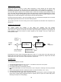
INSTALLATION, START-UP
AND
OPERATION MANUAL
AIR COOLED SCREW
LIQUID CHILLERS
ASQ045B – ASQ440B
INDEX
PAGE
A. GENERAL
Introduction………………………………………………………………………………………………………3
Scope of this Manual……………………………………………………………………………………………3
Safety Consideration & Symbols………………………………………………………………………………3-5
Warranty…………………………………………………………………………………………………………5
B. PRODUCT INFORMATION
Model designation details………………………………………………………………………………………6
Major Features………………………………………………………………………………………………… 6
Standard control & Safety devices and other accessories…………………………………………………7
Optional Features………………………………………………………………………………………………7-8
Physical data ……………………………………………………………………………………………………9-12
13
Microprocessor controller overview……………………………………………………………………………
Basic Refrigerant Flow and Process & Ins. diagram……………………………………………………… 14
C. HANDLING & STORAGE
Inspection……………………………………………………………………………………………………… 15
Rigging Instructions ……………………………………………………………………………………………15-16
Storage instructions……………………………………………………………………………………………17
D. INSTALLATION PROCEDURES
18
Pre-installation guidelines………………………………………………………………………………………
Space Requirements……………………………………………………………………………………………18-26
Clearances………………………………………………………………………………………………………27
Vibration Isolation and Schematic Mounting Layouts………………………………………………………27-29
30
Recommendations for Spring Type Isolator Selection………………………………………………………
31
Load distribution (with aluminium fin condenser coils)………………………………………………………
Load distribution (with copper fin condenser coils)…………………………………………………………32
Unit installation…………………………………………………………………………………………………33
Mounting Points…………………………………………………………………………………………………33-34
Cooler Piping connections ……………………………………………………………………………………34-35
Cooler Connection Types …………………………………………………………………………………… 36
Water Requirements……………………………………………………………………………………………36
Electrical connections, power & control wiring………………………………………………………………37-38
Electrical data……………………………………………………………………………………………………39
Typical schematic wiring diagram…………………………………………………………………………… 40-41
Installation Inspection………………………………………………………………………………………… 42
E. START-UP, COMMISSIONING AND OPERATING PROCEDURES
General………………………………………………………………………………………………………… 43
43
Request for start-up representative……………………………………………………………………………
Pre-start up requisites…………………………………………………………………………………………43-44
Start up of the system………………………………………………………………………………………… 44-45
Lubrication…………………………………………………………………………………………………….. 45
System water flow rate and Pressure drop………………………………………………………………… 45-47
Normal operation and cycling…………………………………………………………………………………48
48
Compressor Staging & sequence of operation.………………………………………………………………
Capacity control steps…………………………………………………………………………………………49
Unit shutdown……………………………………………………………………………………………………49
F. MICROPROCESSOR CONTROLLER DATA
Introduction………………………………………………………………………………………………………50
Master compressor board & slave compressor board………………………………………………………50
Use interface board description………………………………………………………………………………50-51
User sequence of operation……………………………………………………………………………………51
Configuration……………………………………………………………………………………………………51
Software control concept………………………………………………………………………………………51
Temperature control……………………………………………………………………………………………52
52
Controller structure………………………………………………………………………………………………
Staging logic…………………………………………………………………………………………………… 52-53
Compressor switch on procedure…………………………………………………………………………… 53
53
Compressor switch on and off limitation………………………………………………………………………
1
INDEX
PAGE
Discharge pressure control……………………………………………………………………………………54
Electronic expansion valve……………………………………………………………………………………54-55
LCD display data……………………………………………………………………………………………… 55-56
Alarms……………………………………………………………………………………………………………57
Anti-freeze alarm……………………………………………………………………………………………… 57
Oil pressure alarm………………………………………………………………………………………………57
Compressor magnetic circuit breaker…………………………………………………………………………57
Compressor solid state protection system SSPS (winding thermistor)……………………………………57
57
Probe warning……………………………………………………………………………………………………
57
Temperature warning……………………………………………………………………………………………
Suction pressure alarm ……………………………………………………………………………………… 57
58
Discharge pressure alarm………………………………………………………………………………………
High pressure alarm……………………………………………………………………………………………58
Flow switch alarm………………………………………………………………………………………………58
Serial communication alarm……………………………………………………………………………………58
Set-up error………………………………………………………………………………………………………58
Compressor pump down alarm……………………………………………………………………………… 58
Compressor no run alarm………………………………………………………………………………………58
EEV board serial communication alarm………………………………………………………………………58
Fan protection alarm……………………………………………………………………………………………59
SYSTEM SETUP
Set point change…………………………………………………………………………………………………
59
Remote monitoring system……………………………………………………………………………………59-60
TESTING FEATURES
Hardware test mode……………………………………………………………………………………………60-61
Software test mode…………………………………………………………………………………………… 61
I/O CHANNELS
Analog inputs……………………………………………………………………………………………………61
Analog outputs………………………………………………………………………………………………… 61
Digital inputs…………………………………………………………………………………………………… 61-62
Digital outputs……………………………………………………………………………………………………62
62
CONNECTIONS………………………………………………………………………………
MALFUNCTIONS AND CORRECTIVE ACTIONS………………………………………63
APPENDIX
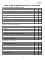
G.
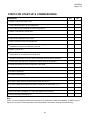
Start-up & commissioning check list…………………………………………………………………………64-65
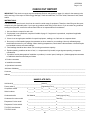
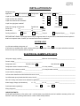
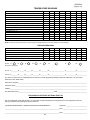
Check - out report………………………………………………………………………………………………66-69
Preventive Maintenance Schedule……………………………………………………………………………70
Troubleshooter's Guide to Chiller problems…………………………………………………………………71-74
Recommended Spare parts……………………………………………………………………………………75
76-78
Major parts list……………………………………………………………………………………………………
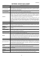
Material safety data sheet (R-134a)………………………………………………………………………… 79
80-81
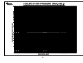
Pressure temperature chart (R-134a)…………………………………………………………………………
Useful equation and Data…………………………...…………………………………………………………82
Symbols used in chiller plant drawings………………………………………………………………………82-84
2
GENERAL
INTRODUCTION
ZAMIL Cooline ASQ-Series liquid chillers are manufactured to provide engineering excellence in comfort air
conditioning and industrial cooling with a superior combination of energy saving, performance, application flexibility,
ease of service & maintenance, environmental friendliness and ability to withstand extreme ambient temperatures.
This manual contains all the information required for correct installation, start-up and commissioning of the units,
together with operating instructions. The manual should be read thoroughly before attempting to perform any of the
aforesaid tasks and all procedures and instructions detailed in this manual must only be carried out by suitably trained
and qualified personnel. The manufacturer will not be liable for any personnel injury or equipment damage caused by
incorrect installation, commissioning or operation resulting from a failure to follow and implement the procedures,
instructions and recommendations detailed in this manual.
SCOPE OF THIS MANUAL
The contents of this manual include suggested best working practices and procedures. These are issued for guidance
only and they do not supersede governing local safety codes/regulations nor the individual responsibility of the
personnel working on these units who shall remain primarily responsible for their own safety and the equipment as
well.
This manual, and any other documents supplied with the unit, are the sole property of Zamil Air Conditioners, which
reserves all rights. They may not be reproduced or distributed in any form or by any means, without prior written
permission from Zamil or its representatives.
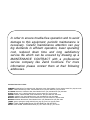
In accordance with our policy for continuous research and product improvement, the information contained in this
manual is subject to change without notice. While Zamil makes no commitment to update or provide current
information automatically to the manual owner, that information, if applicable, can be obtained by contacting the
nearest Zamil or its representative’s offices. It is the responsibility of operating/service personnel to verify applicability
of this manual to the equipment involved. If they have any doubt with regards to the applicability of this document,
then, prior to working on the equipment, they should verify with the owner whether the equipment has been modified/
improved and if current literature is available.
SAFETY CONSIDERATIONS & SYMBOLS
This equipment is a complex engineering product and the personnel involved during installation, operation,
maintenance or service, may be exposed to certain components or conditions including, but not limited to: refrigerants,
oils, pressurized components, rotating parts and both high and low voltages. Each of these items has the potential, if
misused or handled improperly, to cause injury or death. It is the obligation of operating/service personnel to identify
and recognize these inherent hazards, protect themselves and proceed safely in completing their tasks. Failure of the
personnel to comply with any of these requirements could result in serious damage to this equipment and the facility,
in which it is installed, as well as severe injuries or death to themselves and other people at the site.
This manual is intended for use by owner authorized operating/service personnel. It is expected that these personnel
are suitably trained and qualified which will enable them to perform their assigned tasks properly and safely. It is
essential that prior to performing any task on this equipment, the personnel must have thoroughly read and
understood this manual, all tags and stickers on the units and any other applicable documents. These people shall
also be cognizant of and comply with all applicable local codes and regulations pertaining to the job on hand.
The major safety considerations are as follows and must be exercised during application, installation, start-up and
operation of these units:
Proper Design & Operation: These chillers are designed for cooling water or glycol solutions and not suitable for
purposes other than those specified in our application catalogue. Any misuse of this equipment, may result in injury to
the operator or damage to equipment. The units must not be operated beyond the domain of performance data
furnished in our application catalogue.
3
Foundation, Support & Isolation: Suitable structural support and vibration isolation must be provided as indicated in
these instructions. Failure to do so may result in injury to the operator or damage to the equipment and/or building.
Discard Intrusions: The units are not designed to bear additional loads or stresses from adjacent equipment,
pipework or structures. Additional components must not be mounted on these units. Any such external loads may
overload the units and cause structural failure resulting in injury to the operator or damage to equipment.
Restricted Access to Equipment: This equipment is a complex engineering product and there are a number of
areas and features which may be a hazard and potentially cause injury when working on the unit unless suitable
safety precautions are taken. It is necessary to ensure that access to the unit is restricted to suitably qualified
personnel who are familiar with the potential hazards and precautions required for safe operation and maintenance of
this equipment.
High Pressure & Temperature System: The units contain refrigerant vapor and liquid under high pressure and
temperature and release of which can be dangerous and cause injury. The user should ensure that care is taken
during installation, operation and maintenance to avoid damage to the pressure system. Access to component parts
of the pressure system shall be restricted to suitably trained and qualified personnel only.
Electrical: The units must be grounded. No installation or maintenance work should be attempted on the units without
first switching OFF, isolating and locking off the power supply. Work on live equipment must only be carried out by
suitably trained and qualified personnel. No attempt should be made to gain access to the control panel or electrical
enclosures during normal operation of the units.
Rotating Parts: Fan guards must remain fixed in their position at all times and if any need arises to remove them for
inspection or maintenance, then remove the guards only after the power supply has been isolated.
Sharp Edges: The fins on the air-cooled condenser coils have sharp metal edges. Sufficient care should be taken
when working in contact with the coils to avoid the risk of abrasions and lacerations. The use of gloves is
recommended.
Refrigerant and Compressor Oil: Refrigerants and oils used in the units are non-flammable and non-corrosive and
do not pose a serious hazard. However, use of safety shoes, gloves and safety goggles is strongly recommended
when working on these units. Avoid direct skin or eye contact with the refrigerant as it results in frostbite injury.
Further, attention should be given to good ventilation when working in confined or enclosed spaces, as the build-up of
refrigerant vapor, from a leak for example, does pose a risk of asphyxiation.
For more detailed information on safety precautions for use of refrigerant, please refer Material Safety Data Sheet
given in the Appendix of this manual.
High Temperature and Pressure Cleaning: High temperature and pressure cleaning methods like hot water or
steam cleaning should not be used on any part of the pressure system as this will cause excessive pressure in the
system and trigger operation of the pressure relief device(s). Detergents and solvents which may cause corrosion
should also be avoided.
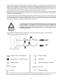
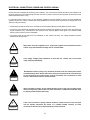
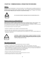
The following symbols are used in this manual to alert the reader:
!
WARNING denotes a potentially hazardous situation which, if not avoided,
could result in serious injury or death.
WARNING
!
CAUTION denotes a hazard which could lead to damage to the unit and damage
to other equipment.
CAUTION
4
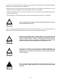
(
ATTENTION is used to remind or highlight useful information.
ATTENTION
WARRANTY
ZAMIL warrants all operating parts in this equipment against factory defects for a period formally agreed upon in the
relevant sales contract. All warranty claims must be supported by proper documentary evidence like copies of
invoices, start-up check out reports, maintenance records etc. to justify the validity of warranty.
In order to avail the warranty, the following requirements must be satisfied:
The initial Start-up and Commissioning of the units must be carried out by suitably trained and qualified personnel
only preferably by Zamil in accordance with the instructions given in this manual.
Upon completion of Start-up and Commissioning, duly filled up and certified check out forms for each unit
(sample check out form given in this manual) should be submitted to Zamil Head Office, Dammam.
This warranty is conditional and nullifies if any of the following violations are committed:
Units are not properly stored, protected or inspected by the client during the period from date of shipment till date
of initial start-up.
Incorrect installation, start-up & commissioning and operation resulting from a failure to follow and implement the
procedures, instructions and recommendations given in this manual.
Equipment is operated without or improperly installed field devices such as water flow switch and chilled water
pump interlocking with chillers.
Any modification to the units which includes changing, adding or removing certain components, altering the
electrical wiring or whatsoever without prior written approval from ZAMIL.
Insufficient maintenance or non-compliance to the maintenance requirements specified in this manual. Also,
maintenance, service or repair carried out by unqualified personnel.
Any misuse of this equipment such as, utilizing it for purposes other than those its designed for and operating
outside the design parameters specified in our application catalogue.
Equipment is operated with refrigerant, oil, water or antifreeze agents which are not approved by ZAMIL.
Equipment has been damaged due to malfunctioning of interface controllers such as DDC, periphery components
etc.
Equipment has been damaged by freezing due to improper protection during cold weather or damaged by
accident, fire or any other conditions not ordinarily encountered (force majeure).
5
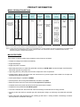
PRODUCT INFORMATION
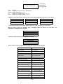
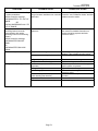
MODEL DESIGNATION DETAILS
1,2 & 3
BASIC
(SERIES)
ASQ COOLINE
AIR COOLED
SCREW WATER
CHILLERS
4,5 & 6
UNIT SIZE
45
50
55
60
70
80
90
100
115
130
140
150
160
170
180
190
200
220
230
240
250
260
270
280
300
320
330
340
350
360
380
400
420
440
7
REFRIGERANT
B:R-134a
9
10
ELECTRICAL
SUPPLY
(V-Ph-Hz)
8
CONDENSER
TYPE
CIRCUIT
BREAKER
OPTIONS
L:380/415-3-50
(4WIRE)
A:ALUMINUM
FINS
A:STANDARD
B:PRECOATED
ALUM FINS
B:COMPRESSOR
CIRCUIT
BREAKER
C: COPPER
FINS
(SEE NOTE 1
BELOW)
11
COOLER
OPTIONS
A:STD. WITH
VICTAULIC
CONNECTION
B:FLANGE
CONNECTION
(OPTIONAL)
12
13 & 14
HGBP
OPTIONS
OPTIONS &
ACCESSORIES
A: STD. UNIT
WITHOUT
HGBP
SEE NOTE # 2
BELOW
B: HGBP
(OPTIONAL)
C: ASME
STAMPED WITH
VICTAULIC
CONNECTION
(OPTIONAL)
D: ASME
STAMPED WITH
FLANGE
CONNECTION
(OPTIONAL)
NOTE 1: FOR OTHER COATING SPECIFY YOUR REQUIREMENTS IN WRITING.
NOTE 2: COMPUTER SELECTED DIGITS (FROM AA to ZZ ) DESCRIBING ALL OTHER FEASIBLE OPTIONS & ACCESSORIES OR COMBINATIONS
THEREOF SUCH AS CONDENSER COIL GUARD, COOLER GUARD, UNIT DISCONNECT SWITCH, COMPRESSOR ENCLOSURE,
WATER FLOW SWITCH, SPRING ISOLATORS ETC.
MAJOR FEATURES
These chillers incorporate a wide range of features; some of them are as follows:
• Compact unit design and excellent serviceability.
• Single skid designed.
• Single point power connection.
• Steel sheet panels are zinc coated and galvanized conforming to ASTM A-653 commercial weight G-90 followed by
electrostatic polyester dry powder coat.
• High energy efficiency ratio (EER) semi-hermetic compact twin screw compressors.
• Compact design shell & tube liquid cooler with enhanced inner grooved copper tubes bundled into U-shape and
expanded into a steel tubular sheet.
• Control panel design is equivalent to NEMA 4.
• Internal power & control wiring cable identification & markers as per NEC.
• Electrical controls used in the control panel are UL approved or equivalent.
• Complete wired control panel with advanced microprocessor based controller.
• Compressors are provided with Part Winding Start.
• Low noise condenser fans, direct drive with rolled venturi design to eliminate short circuiting of airflow.
• All fans are die cast aluminum propeller type with aerodynamic design, top discharge & provided with protective
grille.
• All fan motors are Totally Enclosed Air Over (TEAO) type with class "F" winding insulation, ball bearings & inherent
thermal protection of automatic reset type.
6
STANDARD CONTROL & SAFETY DEVICES AND OTHER ACCESSORIES
The chillers are provided with the following items as a standard practice:
Microprocessor Controller: This controller monitors analog and digital inputs to achieve precise control & safety
functions of the unit.
Compressor In-Built Protection Device: Protect the compressor by monitoring:
a. Motor winding temperature in case of overload.
b. Discharge gas temperature in case of overheating.
c. Phase reversal for direction of rotation.
Starters: The starter is operated by the control circuit and provides power to the compressor motors. These devices
are rated to handle safely both RLA and LRA of motors.
Under/Over Voltage and Phase Protection: Protects against low/over incoming voltages as well as single phasing,
phase reversal and phase imbalance by de-energizing the control circuit. It is an automatic reset device, but it can be
setup for manual reset.
Crankcase Heaters: Each compressor has crankcase heater. The compressor crankcase heater is always on when
the compressors are de-energized. This protects the system against refrigerant migration, oil dilution and potential
compressor failure.
High Pressure Switch: This switch provides an additional safety protection in the case of microprocessor failure to
cut-out on high pressure alarm.
Unit On-Off Switch: On-Off switch is provided for manually switching the unit control circuit.
Indicator Lights: LED lights indicate power ON to the units, MENU adjustment and FAULT indications due to trip on
safety devices.
Electronic Expansion Valves: Electronic expansion valve is used to regulate the refrigerant flow to the water cooler
and maintain a constant superheat and load optimization.
Replaceable Core Type Filter Drier: Refrigerant circuits are kept free of harmful moisture, sludge, acids and oil
contaminating particles by the filter drier.
Control Circuit Transformer: For units rated with 460V-3Ph-60Hz power supply factory mounted and wired control
circuit transformer is furnished eliminating the need for running a separate 220-volt power supply to the unit control
circuit.
Sight Glass: Moisture indicating sight glass installed in the liquid line. An easy-to-read color indicator shows moisture
contents and provides a mean for checking the system refrigerant charge.
Liquid Line Solenoid Valves: Closes when the compressor is off to prevent any liquid refrigerant from accumulating
in the water cooler during the off cycle.
OPTIONAL FEATURES
The chillers can be provided with the following items based on specific client/project requirements:
Hot Gas Bypass System: Hot gas bypass is provided on the lead circuit to permit operation of the system down to
50% of its unloaded capacity. Under low ambient condition, it controls temperature by eliminating the need to cycle the
compressor on and off, ensuring narrow temperature swing and lengthen the life span of the compressor.
Water Flow Switch: Paddle type field adjustable flow switch for water cooler circuits. Interlock into unit safety circuits
so that the unit will remain off until water flow is determined.
Unit Mount Spring Isolators: This housed spring assemblies with a neoprene friction pad on the bottom dampen the
vibration transmission.
7
Compressor Circuit Breakers: Protects against compressor branch circuit fault. When tripped (manually or
automatically), the breaker opens the power supply to the compressor and control circuit through auxiliary contacts.
Liquid Coolers: ASME code stamped liquid cooler.
Pressure Gauges: Suction & discharge pressure gauges.
Non-Fused Main Disconnect Switches: De-energize power supply during servicing/repair works as well as with door
interlock.
Condenser Coil Guard: Protect the condenser coil from physical damage.
Compressor/Cooler Guard: Protect the compressor from vandalism.
Compressor Enclosure Box: Reduce compressor operating noise and keep the compressor clean.
Cooler Heater Wrapped: Prevent freezing up of water on low ambient temperature.
Copper Fins & Tubes Condenser Coils: For seashore salty corrosive environments.
Anti-corrosive Coated Condenser Coils (copper or aluminum fins & copper tubes): For seashore or acid
corrosive environments.
BMS Gateway Interface: Interlocking with Building Management Systems.
(BACnet, MODBUS, GSM and Remote Monitoring).
Ground Fault Protection: Provides additional safety protection in the case of abnormal current leakage.
(
All control & safety devices, accessories and optional items are factory
installed except for unit mounting spring isolators and water flow switch, which
must be installed on job-site.
ATTENTION
8
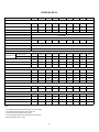
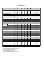
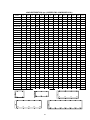
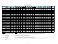
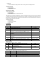
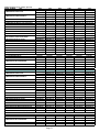
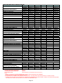
PHYSICAL DATA
UNIT SIZE
ASQ045B
ASQ050B
ASQ055B
ASQ060B
ASQ070B
ASQ080B
ASQ090B
ASQ100B
ASQ115B
80068315
80068315
80068318
80068321
80068324
80068315
80068315
80068318
80068321
NUMBER OF COMPRESSORS
1
1
1
1
1
2
2
2
2
OIL CHARGE/COMPRESSOR (liters)
15
15
22
22
22
15
15
22
22
400
600
600
COMPRESSOR
PART NUMBER (380/415V-3ph-50Hz)
100-25
100-50
CAPACITY CONTROL RANGE (STEPLESS)
ELECTRONIC
MOTOR OVERLOAD PROTECTION (INTERNAL)
INJECTION
OIL LUBRICATION
TOTAL CRANKCASE HEATER WATTS
200
200
300
300
REFRIGERANT
300
400
R-134a
EXPANSION VALVE
ELECTRONIC EXPANSION VALVE
CONTROL VOLTAGE
220V-1Ph-50Hz
AIRCOOLED CONDENSER
3/8-2-14
3/8-2-14
3/8-3-14
3/8-3-14
3/8-4-14
3/8-3-14
3/8-4-14
3/8-4-14
3/8-4-14
87.5
87.5
87.5
87.5
87.5
100.1
100.1
100.1
140
AIRFLOW, CFM
38040
38040
36784
36784
41240
59400
55152
55152
75264
NUMBER OF FANS/FAN DIA; mm
4/762
4/762
4/762
4/762
4/800
6/800
6/800
6/800
8/800
915
915
915
915
860
860
860
860
860
80066091
80066091
80066091
80066091
80066091
80066092
80065905
80065905
80066052
SHELL DIAMETER,mm
273
273
273
273
273
273
324
324
324
TOTAL LENGTH, mm
1850
1850
1850
1850
1850
1850
2180
2180
2697
WATER HOLDING VOLUME, Liters
53.2
53.2
53.2
53.2
53.2
53.2
99.8
99.8
113.5
WATER IN/OUT PIPE DIA. (mm/in)
100/4
100/4
100/4
100/4
100/4
100/4
150/6
150/6
150/6
PART NUMBER.
NA
80051633(1)
NA
NA
NA
NA
80051633(2)
NA
NA
EXPANSION DEVICE
NA
T.E.V.
NA
NA
NA
NA
T.E.V.
NA
NA
1
1
1
1
1
2
2
2
2
CONDENSER COIL
Tube Dia.-Rows-FPI
Total face area, Sq. ft.
FAN MOTOR RPM @ 380-3-50
COOLER
PART NUMBER
ECONOMIZER
GENERAL
NUMBER OF REFRIGERANT CIRCUITS
REFRIGERANT CHARGE, kgs/comp (comp1/2)
27
30
35
38
44
27
30
35
38
SOUND PRESSURE LEVEL,Dba (3m/5m/10m)
72.2/68.7/63.4
72.2/68.7/63.4
72.3/68.8/63.5
75.4/71.9/66.6
75.6/72.1/66.8
74.5/71/65.7
74.5/71/65.7
74.6/71.1/65.8
78.4/74.9/69.6
OPERATING/SHIPPING Wt, kgs
2038/1985
2048/1995
2442/2389
2456/2403
2575/2522
3104/3051
3335/3235
4026/3926
4640/4527
Notes:
1-ALL COMPRESSORS WITH SLIDER CONTROL VALVE UNLOADING
2-ALL COMPRESSORS OPERATE AT 2900 RPM @ 50Hz
3-COOLER VENT AND DRAIN SIZE ARE 1/2" MPT
4-ALL COOLERS ARE SINGLE FACE REFRIGERANT CONNECTION.
5-SOUND PRESSURE LEVEL ± 2 dBA
9
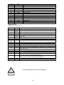
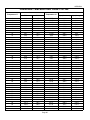
PHYSICAL DATA
UNIT SIZE
ASQ130B
ASQ140B
ASQ150B
ASQ160B
ASQ170B
ASQ180B
ASQ190B
ASQ200B
ASQ220B
80068324
80068324
80068324
80068318
80068318
80068321
80068321
80068324
NUMBER OF COMPRESSORS
2
2
2
3
3
3
3
3
4
OIL CHARGE/COMPRESSOR (liters)
22
22
22
22
22
22
22
22
22
COMPRESSOR
PART NUMBER (380/415V-3ph-50Hz)
100-16.3
100-25
CAPACITY CONTROL RANGE (STEPLESS)
80068321(2)
80068318(2)
100-12.5
ELECTRONIC
MOTOR OVERLOAD PROTECTION (INTERNAL)
INJECTION
OIL LUBRICATION
TOTAL CRANKCASE HEATER WATTS
600
600
600
900
REFRIGERANT
900
900
900
900
1200
R-134a
EXPANSION VALVE
ELECTRONIC EXPANSION VALVE
CONTROL VOLTAGE
220V-1Ph-50Hz
AIRCOOLED CONDENSER
3/8-4-14
3/8-3-14
3/8-4-14
3/8-3-14
3/8-4+3-14
3/8-4-14
3/8-4-14
3/8-4-14
3/8-3-14
140
175
175
210
210
210
210
210
304
AIRFLOW, CFM
75264
100860
94080
121032
115488
112896
112896
112896
166240
NUMBER OF FANS/FAN DIA; mm
8/800
10/800
10/800
12/800
12/800
12/800
12/800
12/800
16/800
860
860
860
860
860
860
860
860
860
80066052
80066055
80066055
80066059
80066059
80066059
80066062
80066062
80066052(2)
SHELL DIAMETER,mm
324
406
406
406
406
406
406
406
324
TOTAL LENGTH, mm
2697
2744
2744
2737
2737
2737
2737
2737
2697
WATER HOLDING VOLUME, Liters
113.5
221.7
221.7
206.5
206.5
206.5
184.4
184.4
227
WATER IN/OUT PIPE DIA. (mm/in)
150/6
200/8
200/8
200/8
200/8
200/8
200/8
200/8
150/6
PART NUMBER.
NA
NA
80051633(2)
NA
80051633(2)
80051633(2)
80051633(3)
NA
NA
EXPANSION DEVICE
NA
NA
T.E.V.
NA
T.E.V.
T.E.V.
T.E.V.
NA
NA
NUMBER OF REFRIGERANT CIRCUITS
2
2
2
3
3
3
3
3
4
REFRIGERANT CHARGE, kgs/comp (comp1/2)
44
44
48
35
39/35
41/38
41/38
44
38/35
SOUND PRESSURE LEVEL,Dba (3m/5m/10m)
78.6/75.1/69.8
78.9/75.4/70.1
78.9/75.4/70.1
77.1/73.6/68.3
77.1/73.6/68.3
80.2/76.7/71.4
80.2/76.7/71.4
80.4/76.9/71.6
80.1/76.6/71.4
OPERATING/SHIPPING Wt, kgs
4675/4562
5277/5055
5423/5201
6797/6591
6920/6714
7007/6801
7041/6857
7051/6867
9130/8903
CONDENSER COIL
Tube Dia.-Rows-FPI
Total face area, Sq. ft.
FAN MOTOR RPM @ 380-3-50
COOLER
PART NUMBER
ECONOMIZER
GENERAL
Notes:
1-ALL COMPRESSORS WITH SLIDER CONTROL VALVE UNLOADING
2-ALL COMPRESSORS OPERATE AT 2900 RPM @ 50Hz
3-COOLER VENT AND DRAIN SIZE ARE 1/2" MPT
4-ALL COOLERS ARE SINGLE FACE REFRIGERANT CONNECTION.
5-SOUND PRESSURE LEVEL ± 2 dBA
10
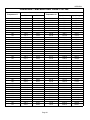
PHYSICAL DATA
UNIT SIZE
ASQ230B
ASQ240B
ASQ250B
ASQ260B
ASQ270B
ASQ280B
80068324
80068324
ASQ300B
ASQ320B
COMPRESSOR
PART NUMBER (380/415V-3ph-50Hz)
80068321
80068324(1) 80068324(2) 80068324(2)
80068321(3) 80068321(2) 80068321(2)
80068318(4)
80068315(2)
80068318
NUMBER OF COMPRESSORS
4
4
4
4
4
4
6
6
OIL CHARGE/COMPRESSOR (liters)
22
22
22
22
22
22
22/15
22
100-12.5
CAPACITY CONTROL RANGE (STEPLESS)
100-8.3
ELECTRONIC
MOTOR OVERLOAD PROTECTION (INTERNAL)
INJECTION
OIL LUBRICATION
TOTAL CRANKCASE HEATER WATTS
1200
1200
1200
1200
REFRIGERANT
1200
1200
1600
1800
R-134a
EXPANSION VALVE
ELECTRONIC EXPANSION VALVE
CONTROL VOLTAGE
220V-1Ph-50Hz
AIRCOOLED CONDENSER
3/8-3-14
3/8-4+3-14
3/8-4-14
3/8-4-14
3/8-4-14
3/8-4-14
3/8-4+3-14
3/8-4-14
304
304
304
304
304
304
430.7
430.7
AIRFLOW, CFM
166240
163616
156192
156192
156192
156192
194004
191160
NUMBER OF FANS/FAN DIA; mm
16/800
16/800
16/800
16/800
16/800
16/800
18/800
18/800
860
860
860
860
860
860
860
860
CONDENSER COIL
Tube Dia.-Rows-FPI
Total face area, Sq. ft.
FAN MOTOR RPM @ 380-3-50
COOLER
PART NUMBER
80066052(2) 80066052(2) 80066052(2) 80066055(2) 80066055(2) 80066055(2) 80066059(2) 80066059(2)
SHELL DIAMETER,mm
324
324
324
406
406
406
406
406
TOTAL LENGTH, mm
2697
2697
2697
2744
2744
2744
2737
2737
WATER HOLDING VOLUME, Liters
227
227
227
443.4
443.4
443.4
413
413
WATER IN/OUT PIPE DIA. (mm/in)
150/6
150/6
150/6
200/8
200/8
200/8
200/8
200/8
PART NUMBER.
NA
NA
NA
NA
NA
EXPANSION DEVICE
NA
NA
NA
NA
NA
T.E.V.
T.E.V.
T.E.V.
4
4
4
4
4
4
6
6
ECONOMIZER
80051633(2) 80051633(2) 80051633(2)
GENERAL
NUMBER OF REFRIGERANT CIRCUITS
REFRIGERANT CHARGE, kgs/comp (comp1/2)
38
44/38
44/38
44/38
44
48/44
35/30
39/35
SOUND PRESSURE LEVEL,Dba (3m/5m/10m)
81.4/77.9/72.6
81.5/77.9/72.7
81.5/77.9/72.7
81.5/77.9/72.7
81.6/78.1/72.8
81.6/78.1/72.8
79.4/75.8/70.6
79.4/75.8/70.6
OPERATING/SHIPPING Wt, kgs
9159/8932
9227/9000
9394/9167
9986/9543
10021/9578
Notes:
1-ALL COMPRESSORS WITH SLIDER CONTROL VALVE UNLOADING
2-ALL COMPRESSORS OPERATE AT 2900 RPM @ 50Hz
3-COOLER VENT AND DRAIN SIZE ARE 1/2" MPT
4-ALL COOLERS ARE SINGLE FACE REFRIGERANT CONNECTION.
5-SOUND PRESSURE LEVEL ± 2 dBA
11
10052/9609 13088/12675 13242/12829
PHYSICAL DATA
UNIT SIZE
ASQ330B
ASQ340B
ASQ350B
ASQ360B
80068318
80068321
80068321
80068321
NUMBER OF COMPRESSORS
6
6
6
6
OIL CHARGE/COMPRESSOR (liters)
22
22
22
22
ASQ380B
ASQ400B
ASQ420B
ASQ440B
80068324
80068324
80068324
6
6
6
6
22
22
22
22
1800
1800
1800
COMPRESSOR
PART NUMBER (380/415V-3ph-50Hz)
CAPACITY CONTROL RANGE (STEPLESS)
80068324(4)
80068321(2)
100-8.3
MOTOR OVERLOAD PROTECTION (INTERNAL)
ELECTRONIC
OIL LUBRICATION
INJECTION
TOTAL CRANKCASE HEATER WATTS
1800
1800
1800
1800
REFRIGERANT
1800
R-134a
EXPANSION VALVE
ELECTRONIC EXPANSION VALVE
CONTROL VOLTAGE
220V-1Ph-50Hz
AIRCOOLED CONDENSER
3/8-4-14
3/8-4-14
3/8-4-14
3/8-4-14
3/8-4-14
3/8-4-14
3/8-4-14
3/8-4-14
430.7
430.7
521.3
521.3
521.3
521.3
521.3
521.3
AIRFLOW, CFM
191160
191160
232936
232936
232936
232936
232936
232936
NUMBER OF FANS/FAN DIA; mm
18/800
18/800
22/800
22/800
22/800
22/800
22/800
22/800
860
860
860
860
860
860
860
860
CONDENSER COIL
Tube Dia.-Rows-FPI
Total face area, Sq. ft.
FAN MOTOR RPM @ 380-3-50
COOLER
PART NUMBER
80066059(2) 80066059(2) 80066059(2) 80066059(2) 80066062(2) 80066062(2) 80066068(2) 80066068(2)
SHELL DIAMETER,mm
406
406
406
406
406
406
457
457
TOTAL LENGTH, mm
2737
2737
2737
2737
2737
2737
2790
2790
WATER HOLDING VOLUME, Liters
413
413
413
413
368.8
368.8
504
504
WATER IN/OUT PIPE DIA. (mm/in)
200/8
200/8
200/8
200/8
200/8
200/8
200/8
200/8
80051633(3)
NA
NA
80051633(3)
NA
NA
T.E.V.
NA
NA
T.E.V.
NA
NA
T.E.V.
T.E.V.
6
6
6
6
6
6
6
6
ECONOMIZER
PART NUMBER.
EXPANSION DEVICE
80051633(3) 80051633(6)
GENERAL
NUMBER OF REFRIGERANT CIRCUITS
REFRIGERANT CHARGE, kgs/comp (comp1/2)
39/35
38
38
41/38
44/38
44
48/44
48
SOUND PRESSURE LEVEL,Dba (3m/5m/10m)
79.4/75.8/70.6
82.9/79.3/74.1
83.1/79.5/74.3
83.1/79.5/74.3
83.2/79.7/74.4
83.3/79.8/74.5
83.3/79.8/74.5
83.3/79.8/74.5
OPERATING/SHIPPING Wt, kgs
13257/12844 13297/12884 13859/13446 13902/13489 13971/13602 14006/13637 14597/14093 14643/14139
Notes:
1-ALL COMPRESSORS WITH SLIDER CONTROL VALVE UNLOADING
2-ALL COMPRESSORS OPERATE AT 2900 RPM @ 50Hz
3-COOLER VENT AND DRAIN SIZE ARE 1/2" MPT
4-ALL COOLERS ARE SINGLE FACE REFRIGERANT CONNECTION.
5-SOUND PRESSURE LEVEL ± 2 dBA
12
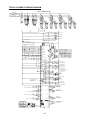
MICROPROCESSOR CONTROLLER
The microprocessor controller works on a state of art microprocessor technology. This controller monitors analog and
digital inputs to achieve precise control & safety functions of the unit.
The Software works on the Proportional Integral Derivative (PID) algorithm for precise control logic.
The simple to use push button keyboard allows accessing to the operating conditions, control set points & alarm
history that are clearly displayed on a multi-line back illuminated LCD panel.
An easy to install serial port/ modem option allows remote monitoring of the operating parameters. With
corresponding windows software, the system allows data to be viewed in tabular or graphic format as well as interact
with system set up. This chiller controller is compatible with Building Management System (BMS) “BAC NET/
MODBUS” protocols through corresponding optional gateway interfaces.
It is also compatible with GSM protocol through GSM optional gateway that sends up to 3 mobile phones SMS
messages whenever alarm takes place, indicating the type of alarm, the corresponding compressor, the related chiller
and which location.
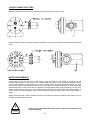
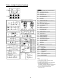
The microprocessor consists of the following hardware:
1.
User Interface Board: Provided with simple to use push button keyboard and menu driven software to access
operating conditions, control set points & alarm history clearly displayed on the LCD panel.
2.
Main Board: This control up to two (2) compressor system.
3.
Auxiliary Boards: Required for controlling an additional two (2) or more compressors.
4.
Remote Monitoring System [Optional]: The micro controller is complete with all hardware and software necessary
to remotely monitor and control the chiller unit.
Display Information:
In the normal operating mode the 20 x 4 characters LCD panel display the system status, the temperature of the water
inlet & outlet, the set point, run time of the compressor & the alarm history.
Easily accessible measurements for each circuit include the following:
• Suction and discharge temperatures
• Suction, discharge and oil pressures
• Water inlet/ outlet temperatures
• Compressor status
• Fan status
• Liquid line solenoid status
• Unit/ Compressor run time
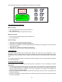
The control temperature is continuously displayed on the 3 Digit 7 segments LED Display. The 3 LED lights indicate
the Power ON, Menu adjustment and Fault.
System protection:
The following system protection is provided to ensure system reliability:
• Compressor winding overheating
• Low suction pressure
• High discharge pressure
• Freeze protection.
• Low oil pressure
• Sensor error
• Time delay – anti recycle time for compressor
• Serial communication error.
13
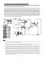
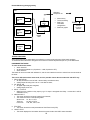
BASIC REFRIGERANT FLOW AND PROCESS & INS. DIAGRAM
These chillers work on the concept of Vapor Compression Refrigeration. At the start of operation cycle, the water (or
other liquid) flows through the water piping system, the flow switch contact is made, and if the controller calls for
cooling and all safety devices are closed, the compressor will start.
The compressor raises the pressure of the refrigerant and it is pumped to the condenser. Since this (high side)
refrigerant temperature is higher than the temperature of the air being passed through the condenser, heat flows from
the hot refrigerant gas to the condenser air. Thus, heat is absorbed by the condenser air from the refrigerant and the
high pressure refrigerant gas changes its phase to high pressure liquid. The high pressure liquid refrigerant then flows
through a filter drier, sight glass/moisture indicator, economizer (if provided) and then liquid line solenoid valve (which
should be open now). The system pressure then forces the liquid into an expansion valve which causes a large
pressure drop and also meters the liquid refrigerant through the evaporator/cooler. The refrigerant then passes
through the tubes inside the cooler while water flows over these tubes, thus heat transfers from the higher
temperature water to the lower temperature refrigerant. The water gets chilled and the liquid refrigerant evaporates
into a gas. The refrigerant is returned back to the suction side (low side) of the compressor as a low pressure gas and
is then ready to be recycled again through the compressor.
Notes:
1.
This P & I diagram illustrate a single refrigeration circuit. Total number of these circuits in a particular chiller shall be as
many as the number of compressors provided in that chiller.
2.
This P & I applicable for a chiller with standard features. For chillers provided with optional features like pressure gauges,
hot gas bypass system, cooler heater, etc. suitable changes in this diagram should be envisaged.
3.
If ‘Economizer’ is provided in a refrigerant circuit, it optimizes the system capacity by further sub cooling the high pressure
liquid refrigerant which increases its thermodynamic efficiency. This is accomplished by a refrigerant to refrigerant brazed
plate heat exchanger in which a portion of the high pressure liquid refrigerant is vaporized thereby sub cooling the remaining
liquid refrigerant. Although this has little effect on the suction capacity of the compressor but the effective refrigerating
capacity of the compressor is boosted by the increased heat absorption capacity of the liquid entering the evaporator/cooler.
4.
The ‘Liquid Injection Circuit’ is provided to allow refrigerant injection for oil cooling. The solenoid valve and liquid injection
valve provided in this circuit open in response to demand sensed by the discharge line temperature sensor (i.e. open when the
refrigerant discharge temperature rises above the set point). The liquid injection valve is required/ provided in the LI circuit
when the refrigeration circuit includes an economizer. In case the refrigeration circuit does not have an economizer, the liquid
injection valve is not required/ provided and the process of liquid injection is accomplished by the LI solenoid valve alone in
conjunction with the chiller controller.
14
HANDLING AND STORAGE
INSPECTION
Upon delivery of equipment, it is important that the following inspection is performed in the presence of transporters
and/or Zamil’s representatives:
• Check all crates and cartons received against the Invoice / shipping papers to be sure they are complete.
• Check model numbers and electrical characteristics on the nameplates of the units delivered to determine if they
are correct.
• Check the loose items/accessories, if supplied any (field installed items like spring isolators & flow switches), Check
for freight damage, shortages or other discrepancies and note them on the delivery receipt before signing and
receiving.
In the event that any damage is found, a damage claim should be immediately filed by the purchasers against the
delivering carrier as all shipments are made at the buyer’s risk. The same should be notified to the concerned Zamil
Office immediately.
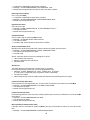
RIGGING INSTRUCTIONS
Each unit has been crafted and carefully tested at the factory where every precaution is taken to ensure that it reaches
you in perfect condition. It is very important that the riggers and movers should use the same care and precaution in
moving the equipment into place. Make sure that chains, slings, cables or other rigging equipment are employed so as
to avoid damage to the units.
Before moving the units, ensure that the site is ready and suitable for installing the equipment and is capable of
supporting the weight of units and all associated equipment.
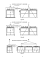
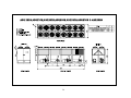
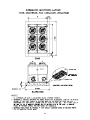
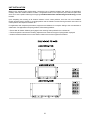
These units are designed for lifting and overhead rigging. Based on weight and dimensions of the units, either rigging
holes are provided in the base rail or lifting eyes extending from the sides of the base rail. These rigging holes or lifting
eyes are centered around the unit center of gravity. For rigging the units, follow these instructions:
• For units with rigging holes in the base rail, insert pipes thru these holes to support the whole unit and lift using
rigging slings and hooks or shackles as shown in Figure A below.
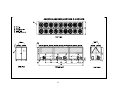
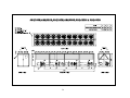
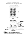
• For units with lifting eyes on the base rail, attach the hooks or shackles directly into them and lift using rigging
slings as shown in Figures B & C below.
• Center of gravity is not unit centerline; ensure center of gravity aligns with main lifting point before lifting.
• Use spreader bars when rigging, to prevent slings from damaging the unit (as shown in Fig. A to C).
!
CAUTION
!
Units must only be lifted from the base and at the points provided.
All unit panels should be in place when rigging.
Extra care must be taken to avoid damage to the condenser coil.
Insert packing material between coils and slings as necessary.
Do not apply pressure to the unit’s body.
Refrigerant piping should never be used as a foothold or handhold.
Never move the unit on roller or using a fork lift truck.
Lifting equipment must be capable of handling the unit weight with adequate
safety factor. For details of unit weights and weight distribution refer to the
Physical data and Load distribution Sections in this manual.
WARNING
15
LIFT
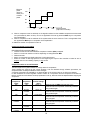
MODELS:ASQ045B TO ASQ200B
LIFT
SPREADER BAR
PROPER CLEARANCE
TO BE PROVIDED
Figure A
LIFT
MODELS:ASQ220B TO ASQ280B
SPREADER BAR
PROPER CLEARANCE
TO BE PROVIDED
Figure B
MODELS:ASQ300B TO ASQ440B
SPREADER BAR
PROPER CLEARANCE
TO BE PROVIDED
Figure C
16
LIFT
STORAGE INSTRUCTIONS
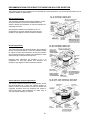
If the unit is to be put into storage prior to installation, observe the following precautions:
• Store in a dry and clean place preferably sheltered or shaded area.
• Place the units on a flat solid surface so that the chiller base does not bend or sag.
• Protect equipment from physical damages, store in a location where there is minimal activity, in order to limit the
risk of accidental physical damage.
• Condenser coils should be securely covered to protect the fins from damage and corrosion, particularly where the
building work is in progress.
• Check that all openings, such as water connections, are securely capped.
• It is recommended that the items/accessories supplied loose and the control panel keys are deposited with a
responsible person.
• It is recommended that the units are periodically inspected as a proactive measure.
17
INSTALLATION PROCEDURES
PRE-INSTALLATION GUIDELINES
These chillers are designed for outdoor installation and can be installed at ground level or on a suitable rooftop
location. In order to achieve good operation, performance and trouble-free service, it is essential that the proposed
installation location meets the following requirements:
• The most important consideration while deciding upon the location of air cooled chillers is the provision for supply of
adequate ambient air to the condenser and removal of heated discharge air from the condenser. This is
accomplished by maintaining sufficient clearances which have been specified in this manual around the units
and avoiding obstructions in the condenser air discharge area to prevent the possibility of warm air circulation.
Further, the condenser fans are propeller type and are not recommended for use with ductwork or other hindrances
in the condenser air stream. Where these requirements are not complied, the supply or discharge airflow
restrictions or warm air recirculation will cause higher condensing temperatures resulting in poor unit operation,
higher power consumption and possible eventual failure of equipment.
• The unit’s longitudinal axis should be parallel to the prevailing wind direction in order to ensure a balanced air flow
through the condenser coils. Consideration should also be given to the possibility of down-drafts caused by
adjacent buildings, which may cause recirculation or uneven unit airflow. For locations where significant cross winds
are expected, an enclosure of solid or louver type is recommended to prevent wind turbulence interfering with the
unit airflow. When units are installed in an enclosure, the enclosure height should not exceed the height of the unit.
• The location should be selected for minimum sun exposure and away from hot air sources, steam, exhaust vents
and sources of airborne chemicals that could attack the condenser coils and steel parts of the unit. Avoid locations
where the sound output and air discharge from the units may be objectionable.
• If the location is an area which is accessible to unauthorized persons, steps must be taken to prevent access to the
unit by means of a protective fence. This will help to prevent the possibility of vandalism, accidental damage or
possible harm caused by unauthorized removal of panels or protective guards exposing rotating or high voltage
components.
• The clearance requirements prescribed in this manual are necessary to maintain good airflow and provide access
for unit operation and maintenance. However, it is also necessary to consider access requirements based on
practical considerations for servicing, cleaning and replacing large components.
• The unit must be installed on a ONE-PIECE, FLAT and LEVELLED {within ½” (13 mm) over its length and width}
CONCRETE BASE that extends fully to support the unit. The carrying or supporting structure should be capable of
handling complete operating weight of the unit as given in the Physical Data tables in this manual.
• For ground level installations, it must be ensured that the concrete base is stable and does not settle or dislocate
upon installation of the unit which can strain the refrigerant lines resulting in leaks and may also cause compressor
oil return problems. It is recommended that the concrete slab is provided with appropriate footings. The slab should
not be connected to the main building foundation to avoid noise and vibration transmission.
• For rooftop installations, choose a place with adequate structural strength to safely support the entire operating
weight of the unit. The unit shall be mounted on a concrete slab similar to ground installations. The roof must be
reinforced for supporting the individual point loads at the mounting isolator locations. It must be checked and
ensured that the concrete base is perfectly horizontal and levelled, especially if the roof has been pitched to aid in
water removal. It should be determined prior to installation if any special treatment is required to assure a levelled
installation else it could lead to the above mentioned problems.
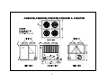
SPACE REQUIREMENTS
Dimensional drawings for all chiller models are given in the following pages. In order to ascertain space requirement
for an installation, refer to the respective chiller drawing:
18
19
20
21
22
23
24
25
26
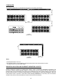
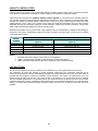
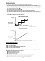
CLEARANCES
The installation clearances to be maintained for the various unit models are as follows:
B
WALL
A
2000
B
FIGURE 1
STRAIGHT WALL
FIGURE 2
CORNER WALL
2000
Notes:
1. All above dimensions are in mm.
2. PIT INSTALLATION: If unit is installed in special pit, please observe the same tolerance for walls.
Pit heights should not exceed Chiller height.
VIBRATION ISOLATION AND SCHEMATIC MOUNTING LAYOUTS
Vibration isolators are necessary for installing these chillers in order to minimize the transmission of vibrations. The
two types of vibration isolators generally utilized for mounting these units are Neoprene Pads and Spring Isolators.
Neoprene Pads are recommended for ground level normal installations jobs where vibration isolation is not critical and
job costs must be kept to a minimum. Spring Isolators are recommended for ground level installations which are
noise-sensitive areas or exposed to wind loads and all roof top installations. For extremely noise and vibration
sensitive areas, follow the recommendations of structural and acoustical consultants.
27
28
29
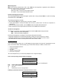
RECOMMENDATIONS FOR SPRING TYPE VIBRATION ISOLATOR SELECTION
The following types of spring isolators are recommended for various applications. Any of these spring isolators can be
supplied by ZAMIL as optional items.
Standard Applications:
The SLR series vertically restrained spring isolation mounts
are recommended as a noise and vibration isolator for
chillers to reduce the transmission of noise and vibration into
supporting structures.
Operating static deflections are available up to 5” to
compensate for long span flexible floor structures and
maintain a high degree of noise and vibration isolation.
Seismic Applications:
The SLRS series vertically restrained seismic spring isolation
mounts are recommended as a noise and vibration isolator
for chillers to reduce the transmission of noise and vibration
into supporting structures in seismic zone applications where
static G ratings in three planes are required.
Operating static deflections are available up to 5” to
compensate for long span flexible floor structures and
maintain a high degree of noise and vibration isolation.
Critical and Noise Sensitive applications:
The SLR-MT vertically restrained air spring isolation mounts
are recommended as a noise and vibration isolator for
chillers to reduce the transmission of noise and vibration into
supporting structures where the equipment are located in
critical areas where noise transmission is a major worry or
very high isolation efficiency is required.
30
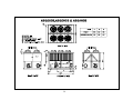
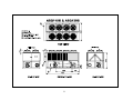
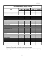
LOAD DISTRIBUTION, kgs. (ALUMINIUM FINS CONDENSER COIL)
MODEL
R1
R2
R3
R4
R5
R6
ASQ045B
520
504
496
453
ASQ050B
523
507
499
455
ASQ055B
650
634
626
524
ASQ060B
655
639
631
527
ASQ070B
686
670
662
555
ASQ080B
594
563
547
ASQ090B
626
594
ASQ100B
779
748
ASQ115B
877
ASQ130B
885
ASQ140B
ASQ150B
R7
R8
493
462
446
578
538
507
491
732
615
584
568
845
830
722
691
675
853
837
726
695
679
734
707
698
688
640
754
726
717
708
657
612
603
594
629
620
611
ASQ160B
968
934
923
911
ASQ170B
985
951
939
928
799
765
754
742
813
779
768
756
R9
R10
805
799
R11
R12
R13
R14
ASQ180B
998
963
952
940
823
788
777
765
ASQ190B
1002
967
956
945
827
793
781
770
ASQ200B
1003
969
958
946
828
794
782
771
ASQ220B
1046
1012
995
989
983
862
828
811
ASQ230B
1050
1016
998
993
987
864
830
813
807
801
ASQ240B
1057
1023
1006
1000
994
871
836
819
813
808
ASQ250B
1075
1040
1023
1017
1012
887
852
835
829
824
ASQ260B
1114
1080
1063
1057
1051
966
931
914
908
903
ASQ270B
1119
1084
1067
1062
1056
968
934
916
911
905
ASQ280B
1123
1089
1071
1066
1060
970
936
918
913
907
ASQ300B
1064
1046
1037
1027
1018
1014
1009
872
854
845
836
827
822
817
ASQ320B
1077
1058
1049
1040
1031
1026
1022
882
864
854
845
836
831
827
ASQ330B
1078
1060
1051
1041
1032
1028
1023
883
864
855
846
837
832
828
ASQ340B
1082
1063
1054
1045
1036
1031
1027
885
866
857
848
839
834
830
ASQ350B
1125
1105
1095
1085
1075
1070
1065
928
908
898
888
878
873
868
ASQ360B
1129
1109
1099
1089
1079
1074
1069
930
910
900
890
880
875
870
ASQ380B
1134
1114
1104
1094
1084
1079
1074
935
915
905
895
885
880
875
ASQ400B
1137
1117
1107
1097
1087
1082
1077
937
917
907
897
887
882
877
ASQ420B
1167
1147
1137
1127
1117
1112
1107
991
971
961
951
941
936
931
ASQ440B
1172
1152
1142
1132
1122
1117
1112
993
973
963
953
943
938
933
R1
R2
R3
R4
R5
R6
R7
R8
R1
R2
R3
R4
R1
R2
R3
R4
R5
R1
R2
R3
R4
R5
R6
R7
R6
R7
R8
R9
R10
R8
R9
R10
R11
R12
R13
R14
R1
R2
R3
R4
R5
R6
31
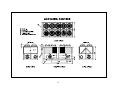
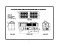
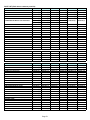
LOAD DISTRIBUTION, kgs. (COPPER FINS CONDENSER COIL)
MODEL
R1
R2
R3
R4
R5
R6
ASQ045B
551
535
527
484
ASQ050B
554
538
531
486
ASQ055B
698
682
675
572
ASQ060B
703
687
679
575
ASQ070B
756
740
732
625
ASQ080B
631
599
584
ASQ090B
679
647
632
530
499
483
592
560
545
ASQ100B
832
801
ASQ115B
951
920
785
669
637
621
904
796
765
749
ASQ130B
959
ASQ140B
782
928
912
800
769
753
755
746
736
688
661
R7
R8
651
642
R9
R10
R11
R12
R13
R14
ASQ150B
824
796
787
778
727
699
690
681
ASQ160B
1026
992
980
969
857
823
811
800
ASQ170B
1060
1026
1014
1003
889
854
843
831
ASQ180B
1081
1047
1036
1024
906
872
861
849
ASQ190B
1086
1051
1040
1028
911
877
865
854
ASQ200B
1087
1053
1041
1030
912
878
866
855
ASQ220B
1113
1079
1061
1056
1050
929
895
878
872
866
ASQ230B
1117
1082
1065
1060
1054
931
897
880
874
868
ASQ240B
1132
1097
1080
1074
1069
945
911
893
888
882
ASQ250B
1172
1137
1120
1114
1109
984
949
932
926
921
ASQ260B
1211
1177
1160
1154
1148
1063
1028
1011
1005
1000
ASQ270B
1216
1181
1164
1159
1153
1065
1031
1013
1008
1002
ASQ280B
1220
1186
1168
1163
1157
1067
1033
1015
1010
1004
ASQ300B
1152
1134
1125
1116
1107
1102
1097
961
942
933
924
915
910
906
ASQ320B
1175
1156
1147
1138
1129
1124
1120
980
962
953
943
934
930
925
ASQ330B
1176
1158
1149
1140
1130
1126
1121
981
962
953
944
935
930
926
ASQ340B
1180
1162
1152
1143
1134
1130
1125
983
964
955
946
937
932
928
ASQ350B
1244
1224
1214
1204
1194
1189
1184
1046
1026
1016
1006
996
991
986
ASQ360B
1248
1228
1218
1208
1198
1193
1188
1048
1028
1018
1008
998
993
988
ASQ380B
1252
1232
1222
1212
1202
1197
1192
1054
1034
1024
1014
1004
999
994
ASQ400B
1256
1236
1226
1216
1206
1201
1196
1055
1035
1025
1015
1005
1000
995
ASQ420B
1286
1266
1256
1246
1236
1231
1226
1109
1089
1079
1069
1059
1054
1049
ASQ440B
1291
1271
1261
1251
1241
1236
1231
1112
1092
1082
1072
1062
1057
1052
R1
R2
R3
R4
R1
R2
R3
R4
R5
R6
R1
R2
R3
R4
R5
R6
R7
R8
R1
R2
R3
R4
R5
R1
R2
R3
R4
R5
R6
R7
R6
R7
R8
R9
R10
R8
R9
R10
R11
R12
R13
R14
32
UNIT INSTALLATION
Based on the specific project requirements, choose the type of vibration isolators best suited for the application.
Carefully select the vibration isolators’ models / configuration based on the respective point loads and place each
mount in its correct position following the foregoing Load Distribution Data and Mounting Points Drawing provided
herewith.
Upon completing the mounting of all vibration isolators in their correct positions, move the unit to its installation
location and then lower it carefully in an upright position onto the vibration mounts ensuring that each mount sits in its
correct position with respect to the base rail.
For applications with neoprene pad isolators, equipment and isolators do not require bolting to the concrete base or
substructure. For applications with spring isolators, follow these guidelines:
• Ensure that all vibration isolators get engaged in the mounting holes provided in the unit base rail.
• Follow the specific instructions for levelling, adjustment etc. based on the type of spring isolator employed.
• Isolators should be bolted to the concrete base or substructure and the equipment to isolators.
33
COOLER PIPING CONNECTIONS
After the unit has been leveled, the external water piping may be made up. The following piping guidelines are served
to ensure satisfactory operation of the units. Failure to follow these recommendations may cause damage to the unit
or loss of performance and may nullify the warranty.
• Water piping must be connected correctly to the unit i.e., water must enter from the inlet connection on the cooler
and leave from the outlet connection.
• A flow switch must be installed in the field piping at the outlet of the cooler (in horizontal piping) and wired back to
the unit control panel using shielded cable. There should be a straight run of piping of at least five pipe diameters
on either side of the flow switch. Paddle type flow switches can be obtained from ZAMIL which are supplied as
optional items.
!
CAUTION
A flow switch is required to prevent damage to the cooler caused by the unit
operating without adequate liquid flow. The flow switch should be connected in
the external interlock as shown in the wiring diagram in the control panel. The
flow switch MUST NOT be used to start and stop the unit.
• The chilled water pump(s) installed in the piping system should discharge directly into the unit cooler. The pump(s)
may be controlled external to the unit - but an interlock must be wired to the unit control panel (as shown in the
wiring diagram) so that the unit can start only upon proof of pump operation.
• Flexible connections suitably selected for the fluid and pressure involved should be provided as mandatory in order
to minimize transmission of vibrations to the piping / building as some movement of the unit can be expected during
normal operation. The piping and fittings must be separately supported to prevent any loading on the cooler.
!
CAUTION
The cooler must be protected by a strainer, preferably of 20 mesh, fitted as
close as possible to the liquid inlet connection, and provided with a means of
local isolation.
34
• Thermometer and pressure gauge connections should be provided on the inlet and outlet connections of each
cooler. Pressure gauges are recommended to check the water pressure before and after the cooler and to
determine if any variations occur in the cooler and system. When installing pressure taps to measure the amount of
pressure drop across the water side of the cooler, the taps should be located in the water piping a minimum of 24
inches downstream from any connection (flange etc.) but as near to the cooler as possible.
• Drain and air vent connections should be provided at all low and high points in the piping system to permit complete
drainage of the cooler and piping as well as to vent any air in the pipes. Hand shut-off valves are recommended for
use in all lines to facilitate servicing.
• The system water piping must be flushed thoroughly before connecting to the unit cooler. The cooler must not be
exposed to flushing velocities or debris released during flushing. It is recommended that a suitably sized bypass
and valve arrangement is installed to allow flushing of the piping system. The bypass can be used during
maintenance to isolate the cooler without disrupting flow to other units.
!
CAUTION
Any debris left in the water piping between the strainer and cooler could cause
serious damage to the tubes in the cooler and must be avoided. The
contractor/owner must also ensure that the quality of the water in circulation is
satisfactory, without any dissolved gases which can cause oxidation of steel
parts within the cooler.
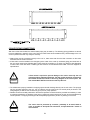
• The following is a suggested piping arrangement at the chiller for single unit installations. For multiple chiller
installations, each unit should be piped as shown:
OUT
IN
Isolating Valve - Normally Open
Pressure tapping
Isolating Valve - Normally Closed
Flow Switch
Balancing Valve
Connection (flanged / Victaulic)
Flow meter
Pipe work
Strainer
Flexible connection
Note: For chillers with two coolers, the connecting pipes for entering and leaving water on one cooler must be joined
to the corresponding pipes on the other cooler before connecting to the main headers in the system piping.
35
COOLER CONNECTION TYPES
Standard chilled liquid connections on all coolers* are of the Victaulic type as shown below:
Flanged Cooler Connections as shown below are available as an option and should be specified with the equipment
order:
WATER REQUIREMENTS
Coolers used in these units are made of carbon steel, copper and brass and are suitable for operation with well
maintained water systems. Using unclean and untreated water may result in scale and deposit formation causing
reduced cooler efficiency or heat transfer and corrosion or pitting leading to possible equipment damage. The more
scale forming material and suspended solids in the system water, the greater the chances of scale and deposit
formation and fouling. These include calcium, magnesium, biological growth (algae, fungi and bacteria), dirt, silt, clays,
organic contaminants (oils), silica, etc. which should be kept to the minimum to retard scale and deposit formation. In
order to prevent corrosion and pitting, the pH value of the water flowing through the cooler must be kept between 7
and 8.5.
ZAMIL recommends that a water treatment specialist is consulted to provide and maintain water treatment, this is
particularly critical with glycol systems.
!
CAUTION
Using unclean and untreated water may result in reduced unit performance and
equipment damage.
36
ELECTRICAL CONNECTIONS, POWER AND CONTROL WIRING
All units are wired completely at the factory prior to delivery. The connections that must be made by the installer are to
the main power source and interlocking with water flow switch, pumps, remote monitoring system and two barrel units
water temperature sensor, if any.
In connecting power wiring to the unit, the following guidelines must be followed to ensure safe and satisfactory
operation of the units. Failure to follow these recommendations could cause harm to personnel or damage to the unit
and may nullify the warranty:
• All field wiring should be carried out in accordance with the National Electrical Code (NEC) and local codes.
• All wiring is to be checked for damages and all terminal connections for tightness. All wiring to the unit should use
copper conductors only, sized based on the minimum circuit ampacity (MCA) values given in the Electrical Data
Section of this manual or the unit nameplate.
• The power supply should match the unit nameplate in volts, phase and Hertz. The voltage imbalance between
phases must not exceed 2%.
!
Main power must be supplied from a single field supplied and mounted Disconnect
switch, using dual element time delay fuse or circuit breaker.
CAUTION
!
If the supply voltage phase imbalance is more than 2%, contact your local electric
utility company immediately.
CAUTION
!
WARNING
!
WARNING
(
ATTENTION
No additional controls (relays, etc.) should be mounted in the unit control panel unless
recommended by Zamil. Power and control wiring not connected to the unit should not
be run through the unit control panel. If these precautions are not observed it could
lead to a risk of electrocution or nuisance faults.
After connection of wiring, do not switch ON main power to the unit out rightly. Some
internal components get live when the main disconnect is switched ON and this must
be done by authorized personnel only.
If the unit is mounted on spring vibration isolators, electrical service to the unit must
also be flexibly connected (by means of a suitable flexible conduit), as some
movement of the unit can be expected during normal operation.
37
In regards to the controls and their wiring, please ensure compliance to the following points to avoid Electro Magnetic
Interference and to optimise the efficiency of EMI filters:
• Make sure that the conducting area around board support holes on main, auxiliary and user boards are very well
grounded to the mounting plates through conducting studs, screws and metal spacers.
• Cables for transducers, sensors, user boards and serial lines must be wired far from high voltage lines like main
power and controls power.
• For shielded cables, connect the shield wire to the ground; exposed wire length must be 15 mm maximum.
!
Control wiring/cables connected to the control panel should never be run in the
same conduit with power wiring.
CAUTION
Some very important recommendations with regard to the main power switching On & Off to these chillers is as
follows. Failure to follow these recommendations could result in serious damage to the equipment:
!
Removing high voltage power (switching OFF the main disconnect) will
disable the 230VAC supply voltage to controls and the compressor crankcase
heaters. At initial start-up or after a prolonged power disconnection, the
crankcase heaters must be energized for a minimum of 12 hours (main
disconnect should be switched ON) before starting/operating the unit.
CAUTION
!
If the unit is located in an area where low ambient temperatures are
encountered, do not disconnect main power unless alternate means are
provided to assure operation of the cooler heater or the liquid system has been
drained completely.
CAUTION
!
After a prolonged power disconnections do not switch ON main power to the
unit unless power supply cables and unit control panel have been properly
inspected.
WARNING
38
ELECTRICAL DATA
Supply Voltage
UNIT SIZE
ASQ045B
ASQ050B
ASQ055B
ASQ060B
ASQ070B
ASQ080B
ASQ090B
ASQ100B
ASQ115B
ASQ130B
ASQ140B
ASQ150B
ASQ160B
ASQ170B
ASQ180B
ASQ190B
ASQ200B
ASQ220B
ASQ230B
ASQ240B
ASQ250B
ASQ260B
ASQ270B
ASQ280B
ASQ300B
ASQ320B
ASQ330B
ASQ340B
ASQ350B
ASQ360B
ASQ380B
ASQ400B
ASQ420B
ASQ440B
LEGENDS:
MCA
MOCP
RLA
LRA
CB
FCA
MTA
MOC
HP
PH
PW
Nominal
(V-Ph-Hz)
380/415-3-50
380/415-3-50
380/415-3-50
380/415-3-50
380/415-3-50
380/415-3-50
380/415-3-50
380/415-3-50
380/415-3-50
380/415-3-50
380/415-3-50
380/415-3-50
380/415-3-50
380/415-3-50
380/415-3-50
380/415-3-50
380/415-3-50
380/415-3-50
380/415-3-50
380/415-3-50
380/415-3-50
380/415-3-50
380/415-3-50
380/415-3-50
380/415-3-50
380/415-3-50
380/415-3-50
380/415-3-50
380/415-3-50
380/415-3-50
380/415-3-50
380/415-3-50
380/415-3-50
380/415-3-50
MIN MAX MCA
342
342
342
342
342
342
342
342
342
342
342
342
342
342
342
342
342
342
342
342
342
342
342
342
342
342
342
342
342
342
342
342
342
342
456
456
456
456
456
456
456
456
456
456
456
456
456
456
456
456
456
456
456
456
456
456
456
456
456
456
456
456
456
456
456
456
456
456
115
123
142
161
184
203
218
251
292
334
340
364
372
406
454
468
484
523
555
578
596
596
634
657
671
734
749
799
811
855
890
927
961
993
COMPRESSOR TYPE1
COMPRESSOR TYPE2
CONDENSER FAN
FLA TOTAL
RLA
LRA
CB
RLA
LRA
CB
CB
CB
MOCP QTY.
QTY.
QTY.
FCA
(each) (each) Poles MTA QTY.
(each) (each) Poles MTA QTY.
(each)
KW
198
1
423
3
66
2
4
3.12
4.40
12.48
82.4
212
1
423
3
71
2
4
3.12
4.40
12.48
88.8
245
1
520
3
83
2
4
3.12
4.40
12.48
103.5
281
1
612
3
95
2
4
3.12
4.40
12.48
119.2
322
1
665
3
110
2
4
3.00
5.40
12
137.8
286
2
423
3
66
4
6
3.00
8.10
18
82.4
307
2
423
3
71
4
6
3.00
8.10
18
88.8
354
2
520
3
83
4
6
3.00
8.10
18
103.5
411
2
612
3
95
4
8
3.00
10.80
24
119.2
472
2
665
3
110
4
8
3.00
10.80
24
137.8
478
2
665
3
110
4
10
3.00
13.50
30
137.8
512
2
665
3
119
4
10
3.00
13.50
30
148.3
476
3
520
3
83
6
12
3.00
16.20
36
103.5
524
2
520
3
95
4
1
520
3
83
2
12
3.00
16.20
36
118.3
103.5
587
2
612
3
106
4
1
612
3
95
2
12
3.00
16.20
36
132.8
119.2
600
3
612
3
106
6
12
3.00
16.20
36
132.8
622
3
665
3
110
6
12
3.00
16.20
36
137.8
642
2
612
3
95
4
2
520
3
83
4
16
3.00
21.60
48
119.2
103.5
674
4
612
3
95
8
16
3.00
21.60
48
119.2
716
1
665
3
110
2
3
612
3
95
6
16
3.00
21.60
48
137.8
119.2
734
2
665
3
110
4
2
612
3
95
4
16
3.00
21.60
48
137.8
119.2
734
2
665
3
110
4
2
612
3
95
4
16
3.00
21.60
48
137.8
119.2
771
4
665
3
110
8
16
3.00
21.60
48
137.8
806
2
665
3
119
4
2
665
3
110
4
16
3.00
21.60
48
148.3
137.8
775
4
520
3
83
8
2
423
3
71
4
18
3.00
24.30
54
103.5
88.8
852
2
520
3
95
4
4
520
3
83
8
18
3.00
24.30
54
118.3
103.5
867
3
520
3
95
6
3
520
3
83
6
18
3.00
24.30
54
118.3
103.5
918
6
612
3
95
12
18
3.00
24.30
54
119.2
930
6
612
3
95
12
22
3.00
29.70
66
119.2
988
3
612
3
106
6
3
612
3
95
6
22
3.00
29.70
66
132.8
119.2
1028
4
665
3
110
8
2
612
3
95
4
22
3.00
29.70
66
137.8
119.2
1065
6
665
3
110 12
22
3.00
29.70
66
137.8
1110
3
665
3
119
6
3
665
3
110
6
22
3.00
29.70
66
148.3
137.8
1141
6
665
3
119 12
22
3.00
29.70
66
148.3
-Minimum Circuit Ampacity per NEC 430-24
-Maximum Over Current Protection
-Rated Load Amps
-Locked Rotor Amps
-Circuit Breaker
-Fan Circuit Amps
-Must Trip Amps
-Max. operating current
-Horse Power
-Phase
-Part Winding Start Compressor
CB
QTY
2
2
2
2
2
3
3
3
4
4
5
5
6
6
6
6
6
8
8
8
8
8
8
8
9
9
9
9
11
11
11
11
11
11
CRANKCASE HEATER
COMP.
Total Total
WINDING
Volts
Watts Amps
230
200
PW
0.87
230
200
PW
0.87
230
300
PW
1.30
230
300
PW
1.30
230
300
PW
1.30
230
400
PW
1.74
230
400
PW
1.74
230
600
PW
2.61
230
600
PW
2.61
230
600
PW
2.61
230
600
PW
2.61
230
600
PW
2.61
230
900
PW
3.91
230
900
PW
3.91
230
900
PW
3.91
230
900
PW
3.91
230
900
PW
3.91
230
1,200
PW
5.22
230
1,200
PW
5.22
230
1,200
PW
5.22
230
1,200
PW
5.22
230
1,200
PW
5.22
230
1,200
PW
5.22
230
1,200
PW
5.22
230
1,600
PW
6.96
230
1,800
PW
7.83
230
1,800
PW
7.83
230
1,800
PW
7.83
230
1,800
PW
7.83
230
1,800
PW
7.83
230
1,800
PW
7.83
230
1,800
PW
7.83
230
1,800
PW
7.83
230
1,800
PW
7.83
NOTES:
1. Main power must be supplied from a single field supplied and mounted fused disconnections using dual element time delay fuse or circuit breaker.
2. The maximum incoming wire size is 500MCM. On units having MCA greater than 500MCM wire, the factory supplied terminal block will accept two or more parallel field wires per pole phase
3. The compressor crankcase heaters must be energized for 12 hours before the unit is initally started or after a prolonged power disconnection.
4. All Field Wiring must be in accordance with NEC and local standards.
5. Minimum and Maximum unit supply voltage are shown in the tabulated data above.
6. Neutral line is required on 380/415V-3Ph-50Hz (4 wires) power supply.
7. The + / - 10 % voltage variation from the nominal is accepted for short time and not permanent.
8. Customer to specify the exact nominal power supply available at the site so that electrical components are selected accurately, failing to do so will affect unit performance & terms of warranty
9. Under compressor type 1 are the big compressor or compressor with economizer and under type 2 are the small compressor or compressor without economizer.
39
TYPICAL SCHEMATIC WIRING DIAGRAM
(PART WINDING START)
HVTB
L1
POWER SUPPLY
380V-3PH-60HZ & NEUTRAL
380V/415V-3PH-50HZ & NEUTRAL
SEE UNIT NAME PLATE
L2
L3
CC4
OLR3 OLR2
OLR4
T1B
T2B
T3B
CB17
CB18
FMC1
CB20
L1J
L1K
L1L
L2I
L2J
L2K
L2L
L3I
L3J
L3K
FMC2
FMC3
L3L
FMC6
FMC5
FMC4
FMC7
FMC8
1B
FM
8
FM
4
FM
2
2
230V-1PH
CCA1-1
3A
CCA2-1
3B
COMP2 OILHTR
2HTR
T1
CCA3-1
1J
T1
CCA4-1
1K
ATB
COMP1 OILHTR
1HTR
SSPS1
D1
SSPS2
D1
T2
T2
COMP1 SSPS
COMP2 SSPS
S1( CONTROL POWER)
SERIAL CABLE
UVR
1
1A
230VAC
(SEE UVM CONNECTION)
TRANS
4 24VAC
SSPS1
8A
MB
5
6
HPS2
10B
FLS
9A
A4/D4(HPS-1)
EEV
11B
AO1
+
A6/D6(SSPS-2)
(See Circuit Breaker Option)
10
9B
A9/D9(HPS-2)
A02
+
A10/D10(FCB-2)
A11/D11(FLW)
2G
1
2H
5A
A8/D8(OL-2)
11
1
2A
A7/D7(CB-2)
OLR4-1
CWP*
EEVB
7
A3/D3(OL-1)
8B
OLR2-1
2
TRANS2
A2/D2(CB-1)
A5/D5(FCB-1)
JP3
JP3A
TO ATB
230VAC
A1/D1(SSPS-1)
JP2
(See Circuit Breaker Option)
JP2A
OLR3-1
OLR1-1
HPS1
10A
11A
SSPS2
1
2B
5B
A12/D12 (EXT. ENABLE)
12/24VAC
+
X9
A1
V1 +
+
B1
DIP S1
4
3
2
1
+
A2
V2
+
+
B2
PE
-
X1 RED
EEVB JUMPER & DIP SWITCH
X1 GRN
EEV
1
X1 WHT
X1 BLK
EEV CARD
TU1
CLOSED
TL1
OPEN
JU1
OPEN
X2 RED
X2 GRN
EEV
2
X2 WHT
CLOSED
TD1
S1
(DIP)
ALCO
X2 BLK
1
2
3
EX7
OFF
ON
OFF
ON
EX8
OFF
ON
ON
OFF
PE
A13/D13 (EMERGENCY)
AC/DC(DIGITAL COM)
R1(DIG OUT)
1C
3C
R5(DIG OUT)
R8(DIG OUT)
14A
UL3-1
4O
12B
CC2
6O
R7(DIG OUT)
7C
8C
3O
R10(DIG OUT)
R11(DIG OUT)
R12(DIG OUT)
C
INTERFACE
(SEE OPTION BOX)
COM2
HOT GAS BYPASS SOLENOID
18A
10O
19A
12O
20A
13O
18B
R14(DIG OUT)
14O
19B
R15(DIG OUT)
15O
R16(DIG OUT)
16O
17O
18O
22A
T1S
SUCTION TEMP SENSOR COMP1
23A
ST1
(A1-ST1)
O1
(A5-SP1)
SH
ALARM - NC CONTACT
FMC1
FMC2
FMC3
FMC4
11O
R18(DIG OUT)
18C
ALARM - NO CONTACT
16
9O
R17(DIG OUT)
17C
+
LIQUID LINE SOLENOID2
POWER DECREASE CP2
6A
R13(DIG OUT)
REMOTE MONITORING
COMP2 CONTACTOR
7O
8NO
R9(DIG OUT)
LIQUID LINE SOLENOID1
POWER DECREASE CP1
UL3-2
14B
8NC
C
COMP1 CONTACTOR
LLS2
5O
R6(DIG OUT)
6C
CC1
LLS1
R4(DIG OUT)
5C
12A
2O
R3(DIG OUT)
4C
7A
1O
R2(DIG OUT)
2C
20B
SL.I1
LIQUID INJECTION 1
FMC5
FMC6
FMC7
FMC8
LIQUID INJECTION 2
UL4-1
15B
UL4-2
29A
CTR-FAN 4
CTR-FAN 8
CTR-FAN 2
CTR-FAN 6
SL.I2
15A
28A
CTR-FAN 3
CTR-FAN 7
CTR-FAN 1
CTR-FAN 5
POWER INCREASE CP1
POWER INCREASE CP2
- SPT1 - COMP1
SUCTION PRESSURE
+ TRANSDUCER
SH
24A
(A2-TOUT)
T2S
TOUT/LWT TEMP. SENSOR
25A
TOUT
T3S
SUCTION TEMP SENSOR COMP2
23B
D1
(A6-DP1)
+
22B
30A
31A
- DPT1 - COMP1
DISCHARGE PRESSURE
+ TRANSDUCER
ST2
(A3-ST2)
O1
(A7-OP1)
+
SH
SH
26A
T4S
TIN/RWT TEMP. SENSOR
27A
-
28B
+
29B
S2
TIN
(A4-TIN)
(A8-SP2)
JU1
- SPT2 - COMP2
SUCTION PRESSURE
+ TRANSDUCER
JU2
TU1
TD1
JUMPER & DIP SWITCH
SELECTION ON MAIN BOARD
CLOSED
JU1
JU2
TU1
TD1
TL1
S1
(DIP)
1
ON
CLOSED
CLOSED
CLOSED
OPEN
2
3
OFF OFF
ON
On/Off
4
OFF
D2 -
TL1
TOUT=10°C TIN=15°C
COOLING 75%
SET
(A9-DP2)+
S1
USER INTERFACE BOARD
SH
*
1 2 3 4
MENU *
ESC
DIP
*
SERIAL CABLE
O2 -
X53
X52
GND
(A10-OP2) +
40
30B
31B
- DPT2 - COMP2
DISCHARGE PRESSURE
+ TRANSDUCER
4
37F
36F
35F
37B
36B
35B
37H
36H
35H
37D
36D
FM
5
FM
1
TO NTB
N
CONTROL VOLTAGE
F1 5A
35D
37E
36E
35E
37A
36A
35A
FM
7
FM
3
TO HVTB
L1
ATB
37G
37C
35C
2
35G
COMP
1
36C
COMP
CB19
L1I
36G
T1A
T2A
T3A
T1C
T2C
T3C
OLR1
NTB
CC2
CC3
T1D
T2D
T3D
ETB/LUG CC1
FM
6
TYPICAL SCHEMATIC WIRING DIAGRAM
COMP LAYOUT
COMP1
COMP2
CONTROL PANEL
FAN LAYOUT
COMP FAN 1
FAN1
CONTROL PANEL
FAN3
FAN2
FAN5
FAN4
FAN7
FAN6
FAN8
COMP FAN 2
COMPRESSOR PART WIND WITH CIRCUIT BREAKER OPTION
LPS CONNECTION WITH OUT CB (OPTIONAL)
L1
MAIN BOARD
A7/D7
CC1
OLR1
LPS1
63A
CB1A-1
D2(MB)
CB3A-1
22A
23A
LPS2
1
63B
CB2A-1
CB4A-1
22B
23B
REMOVE JP3
CC2
OLR2
COMP
2
CBA4-1
CBA2-1
22B
1
CC1
CC2
2
12A
CC1A-2
TO
CC2A-2
61A
2
CC1A-2
1
ECONOMIZER CONNECTION (OPTIONAL)
2 ECONOMIZER 1
62A
TO MB (50)
2 ECONOMIZER 2
EQUALIZER CONNECTION (OPTIONAL)
TO CCA1-1
TO CCA2-1
3A
SL.E1
3B
SL.E2
2 EQUALIZER 1
2 EQUALIZER 2
2
CC4
TDS2-1SEC
61B
62B
2
L1
L2
L3
NOTE:
TERMINAL A,B,& C
ON UVM TO BE
PHASE MATCHED WITH
UNIT CONTROLS.
1A
UVR
UVM
1
GROUND FAULT PROTECTION OPTION.(GFP)
COMP
UNIT EXTERNAL ENABLE/DISABLE OPTION
VFC FROM CUSTOMER PANEL
ATB
1
TI
Current Transformer
wire number, 70A/71A for
Comp 1 and 70B/71B for
Comp 2.
UNIT EMERGENCY OPTION
31
32
ATB
2H
VFC FROM CUSTOMER PANEL
VFC
1
71A/B
ATB
2G
VFC
ATB
1
2
70A/B
Comp 1
1
T2
A1 A2
EARTH FAULT RELAY
32 31 34
A3/D3 (MB)
65A
REMOVE JP2A
EFR1
32
HOT GAS BYPASS OPTION
Comp 2
MB
1
7C
R7
7O
HGBS
15
EFR2
MB
R7
X7
C1
15
HEATER
X8
C2
T1
2
T2
IF THE COLLER HEATER TAPE IS ENABLE HGBS IS NOT POSSIBLE
CWP
CHILLED WATER PUMP
DT
DISCHARGE TEMPERATURE SENSOR
ETB
EARTH TERMINAL BLOCK
FLS
FLOW SWITCH
FM
FAN MOTOR
FMC
FAN MOTOR CONTACTOR
FT
THERMAL MAGNETIC CB FAULT TRIP CONTACTS
F
FUSE
HPS
HIGH PRESSURE SWITCH
HVTB
HIGH VOLTAGE TERMINAL BLOCK
HGBS
HOT GAS BYPASS SOLENOID
OLR
OVERLOAD RELAY
JP
JUMPER
NTB
NEUTRAL TERMINAL BLOCK
PT
PRESSURE TRANSDUCER
P
PROPORTIONAL BAND
S1
CONTROL SWITCH
SSPS
SOLID STATE PROTECTION SYSTEM
TRANS TRANSFORMER
TDS
TIME DELAY SWITCH
TS
TEMPERATURE SENSOR
UVM
UNDER VOLTAGE MONITOR
LOW PRESSURE SWITCH
TL2
OPEN
TD2
CLOSED
MB
MASTER/ MAIN/ MOTHER BOARD
TU2
CLOSED
SB
SLAVE/ AUXILLIARY BOARD
JU11
1-2 CLOSED
SLE
ECONOMIZER SOLENOID
JU13
1-2 CLOSED
UL
UNLOADER
JU15
1-2 CLOSED
JU5
1-2 CLOSED
JU6
1-2 CLOSED
JU7
1-2 CLOSED
JU8
1-2 CLOSED
JU9
1-2 CLOSED
JU4
1-2 CLOSED
A../D..
DIGITAL INPUT1
JU3
1-2 CLOSED
C/1C..
COMMON
JU19
1-2 CLOSED
JU12
1-2 CLOSED
JU10
1-2 CLOSED
DT1
D1
ONLY
7O
COMPRESSOR
UNDER VOLTAGE RELAY
USE FOR
0B1 EEVB
COMP.CONTACTOR AUXILIARY
COMP
LPS
** DISCHARGE TEMP SENSOR CONNECTION
COOLER HEATER TAPE OPTION
7C
A8/D8 (MB)
65A
REMOVE JP3A
COMPRESSOR CONTACTOR
CCA
UVR
2
IF THE HGBS IS ENABLE COOLER HEATER TAPE IS NOT POSSIBLE
1
31
1
THERMAL MAGNETIC CIRCUIT BREAKER AUXILIARY
CC
JUMPER SETUP ON
MAIN BOARD
UVM CONNECTION
ECO2
13B
2
CC3
TDS1-1SEC
1
ECO1
61B
1
61A
CC2A-2
13A
CC4
FOR PART WIND START TIME DELAY SWITCH (TDS) OPTION
GATEWAY
TO MB (20)
2
12B
CC3
1
TO MAIN
BOARD (COM2)
IS485
23B D7 (MB)
COMPRESSOR CONTACTOR CONNECTION FOR PART WIND START
REMOTE MONITORING CONNECTION (OPTIONAL)
GND
+
CC4
OLR4
1
CBA3-1
CBA1-1
22A
23A D2 (MB)
1
CB4
COMP
REMOVE JP2
D7(MB)
CB2
CC3
OLR3
T1A
T2A
T3A
LPS CONNECTION WITH CB (OPTIONAL)
1
CB3
CB1
L1A
L2A
L3A
63B
L1D
L2D
L3D
HVTB
LPS2
T1D
T2D
T3D
1
L1B
L2B
L3B
REMOVE JP3
L2
L3
A2/D2
T1B
T2B
T3B
1
L1C
L2C
L3C
REMOVE JP2
63A
T1C
T2C
T3C
LPS1
CBA
DT2
D2
FIELD WIRING
TERMINAL BLOCK OR TERMINATION POINT
*
FIELD SUPPLY
LEGENDS ON MAIN BOARD
1O...
DIGITAL OUT 1
DC
DIGITAL COMMON
T1
THERMISTOR 1
SH
SHIELD
X52/X53
SERIAL COMMUNICATION PORT
PE
POTENTIAL EARTH
JU/TU/TL/TD BOARD JUMPERS
EEVB
NOTES
1. FUSES TO BE DUAL ELEMENT TYPE.
2. ALL FIELD WIRING TO COMPLY WITH LOCAL CODES.
3. USE COPPER CONDUCTORS ONLY.
4. DISCONNECT MEANS AND BRANCH CIRCUIT PROTECTION
SHALL BE PROVIDED BY INSTALLER
5. IF POWER SUPPLY HAS BEEN INTERRUPTED FOR A
LONG PERIOD, CRANKCASE HEATERS MUST BE ENERGIZED
FOR 12 HRS. MINIMUM, BEFORE STARTING THE COMP.
6. NEUTRAL LINE REQUIRED ON 380V-3Ph-60Hz
POWER SUPPLY ONLY.
41
INSTALLATION INSPECTION
It is the responsibility of contractor or owner to verify and ensure that the following essential requirements are
complied:
Unit installed on flat concrete base and meets the specified clearances.
Vibration isolators are installed properly.
Ensure that all valves including balancing valves, globe valves, stop valves, motorized valves, drain
& air vent connections and flow meters are installed as per the requirement.
Temperature and pressure gauges provided at inlet and outlet piping of the cooler.
Ensure that all temperature and pressures gauges provided on the system are duly calibrated.
Strainer is installed on chilled water inlet to the unit.
Water flow switch is provided and at its correct location.
Field wiring is complete and all sensors and switches interlocked with the controller.
All optional sensors, gauges, valves etc. if any are installed and connected to the controller.
Ensure that chilled water pump is interlocked with the controller.
Chilled water pumps are suitable to handle the required flow rate, head etc.
All wiring connections are tight.
Unit control panels have the proper schematic diagrams.
Ensure compressor-mounting retainer brackets are removed and adjust the bolts.
Ensure that all condenser fans motor propellers are tightened.
Flexible connections provided at interconnection with chilled water piping and power cable entry.
Chilled water lines to the cooler are insulated.
Check for proper grounding of the chiller.
42
START-UP, COMMISSIONING & OPERATING PROCEDURES
GENERAL
The Start-up and Commissioning of units must be carried out by suitably trained and qualified personnel only
preferably by Zamil in accordance with the following instructions. Upon completion of Start-up and Commissioning,
duly filled up and certified check out forms for each unit (sample check out form given in appendix of this manual)
must be forwarded to Zamil Head Office - Dammam in order to avail the warranty.
!
Do not start the unit before completing start-up and commissioning service.
CAUTION
REQUEST FOR START-UP REPRESENTATIVE
Start-up service is provided by Zamil as optional and should be requested when the units are ordered. When
rendering the start-up service, a representative will be sent to the site upon proper completion of installation.
The contractor/owner should have competent service and operating personnel in attendance to assist in the work
involved and also to be trained in the operation and maintenance of these units.
The representative shall perform the following duties:
• Inspection of installation to verify compliance to all essential requirements.
• Perform the Start-up & Commissioning of units and ensure they are operating satisfactorily.
• Instruct the concerned personnel for the specified length of time as agreed in the contract on proper operation and
maintenance of these units.
!
CAUTION
Compressor crankcase heaters should be energized a minimum of 12 hours
prior to Start-up. This will ensure that the compressor lubricating oil is warm
enough to vaporize any dissolved refrigerant and that the oil is within the
normal operating temperature range.
PRE-STARTUP REQUISITES
The unit is ready for start-up when the following procedures have been completed:
• Installation is complete and has been thoroughly inspected / verified as instructed earlier in this manual.
• Ensure that all piping has been completed and tested. Water piping and cooler are filled with clean treated water. If
o
ambient temperatures are expected to fall below liquid freezing point (0 C for pure water) add pre-determined
amount of non-corrosive anti-freeze (Ethylene glycol) to prevent freeze-up.
• Unit has been leak tested, leaks corrected and charging completed.
• Electrical connections are made and properly fused.
• Compressor crankcase heaters have been energized for a minimum of 12 hours.
• Check all refrigerant valves to be sure they are open.
43
• Turn on the chilled water pump, check direction of rotation and adjust the water flow through the cooler to the
specified flow rate. Bleed off all entrained air.
• Calibrated pressure gauges have been connected to the suction, discharge and oil pressure ports.
• Manually energize the condenser fan starters and check the fan rotation which can be changed on 3-phase motors
by interchanging any two wires on the main terminal block.
• Check the power supply voltage. Do not operate the unit if voltage deviation is not within acceptable range
(acceptable voltage range is ± 10% of the rated nominal voltage - temporarily).
!
Do not utilize generator power for Start-up & Commissioning or Operating
these units, it could be detrimental for this equipment. Consult Zamil for further
information and guidance in this regard.
CAUTION
START-UP OF THE SYSTEM
!
CAUTION
(
(
During Start-up and Commissioning, there should be sufficient heat load to run
the unit under stable full load operation to enable the unit controls, and system
operation to be set up correctly and a commissioning log taken. Ensure that
the Microprocessor Controller is properly programmed - refer to the relevant
section in this manual.
Make use of the Start-up and Commissioning checklist provided in the
Appendix section of this manual for step by step guidelines to accomplish this
task.
ATTENTION
Controller Setpoints:
Adjust the controller custom set points as necessary following the instructions given in Microprocessor Controller
section of this manual and ensuring compliance with the requirements. If you are not sure of the appropriate set
points, do not try to change/modify the current set point and contact ZAMIL for guidance.
Start-up:
• Start the unit by pushing ON/OFF key in the controller. The ON LED is lit.
• After 15 seconds delay, the unit is operational.
• At first call for cooling, the controller will de-energize the crankcase heater and start one condenser fan.
• After 20 seconds from condenser fan operation, the lead compressor and liquid solenoid valve are operated.
• Allow the unit to stabilize and confirm proper operation before moving to SYSTEM CHECKOUT.
• To halt the unit, press again ON/OFF key and the ON LED is off.
Notes:
Rate of compressor staging and bringing on more compressors depends on load requirement sensed via
Leaving Water Temperature (LWT).
44
System Checkout:
• Check all operating pressures & temperatures and subcooling & superheat.
• Check liquid line sight glass. The refrigerant shall be bubbles-free clear liquid. Existence of bubbles indicates under
charged circuit.
• Check the compressor crankcase sight glass for oil level. It should be at or slightly above the center of this sight
glass while the compressor is in operation. If not, see below mentioned instructions on “Lubrication”.
• Safety controls are factory set and must be maintained at settings indicated on the wiring diagram.
• Check the water temperatures (both in and out) and water flow rate to ensure that unit is operating within the
specified limits. See below mentioned instructions on “System Water Flow Rate and Pressure Drop” for further
information.
• Check compressor spring suspension for any unacceptable waving.
• Follow the guidelines given in Start-up & Commissioning checklist provided in this manual to complete this work.
External Enabling:
To make the unit start and stop from a remote switch an EXEN (External Enabling) input is supplied:
• Unit must be set the first time in on status through the ON/OFF key (the green led should therefore be ON).
• The auto-restart mode should be selected in set-up (P22 = 1) to allow the system to remember its status even after
a loss of power supply.
• If the EXEN input is energised the machine is stopped (using the pump down procedures but without enabling the
multiple pump downs) and the display shows “LOCK: REMOTE OFF”.
• If the input is not energised the units run normally starting with the normal staging.
(
ATTENTION
In OFF status - the green LED off.
If the EXEN input is energised the display shows “LOCK: REMOTE OFF”.
If the EXEN input is not energised the display shows regularly “SYSTEM OFF”.
To toggle the unit status from off to on and from on to off the ON/OFF key
should be normally used.
LUBRICATION
A properly operated unit should run with the compressor crankcase bottom warm to touch. Check oil level frequently
to see that a sufficient amount of oil remains in the crankcase. Compressor oil level can be checked by sight glass.
To make sure that proper oil level is observed, operate the compressor and oil level should appear within the sight
glass range. For further information on oil adding/charging, oil contamination etc., refer to the Maintenance Manual.
SYSTEM WATER FLOW RATE AND PRESSURE DROP
The quantity of chilled water being circulated can be estimated by determining the water pressure drop through the
cooler and reading GPM from the appropriate pressure drop curve. An alternate method of determined GPM is to
measure pressure difference from pump inlet to outlet and read GPM from pump curve.
During unit operation, water flow rate must not vary more than ± 5% from the design flow rate. The water flow switch
should be calibrated accordingly. The maximum and minimum water flow rates for all unit models and the pressure
drop chart are given below. The design and operating flow rates must be within this range.
45
Model
ASQ-B
045
050
055
060
070
080
090
100
115
130
140
150
160
170
180
190
200
220
230
240
250
260
270
280
300
320
330
340
350
360
380
400
420
440
CURVE NO.
MINIMUM GPM
Maximum GPM
1
1
1
1
1
1
2
2
3
3
4
4
5
5
5
6
6
3
3
3
3
4
4
4
5
5
5
5
5
5
6
6
7
73
82
87
92
111
125
165
165
197
227
239
279
267
305
321
338
336
377
388
406
430
439
470
504
526
567
584
566
594
640
657
686
773
827
122
125
149
163
189
219
242
273
322
353
382
397
435
456
494
516
544
615
638
657
680
722
757
768
833
887
895
943
972
992
1070
1104
1167
1184
7
CONVERSION FACTOR
!
: GPM = 0.063 L/S
: ftH2O=2.989 kPA
The above water flow rate limits must not be exceeded at any time. Operation
outside this range might result in cooler failure. Special care should be taken
when multiple chillers are fed by a single pump.
CAUTION
(
When using glycol solution, flow rate and pressure drop are higher than with
water. Special care must be taken not to exceed the limits. Consult Zamil for
further information and guidance in this regard.
ATTENTION
46
NORMAL OPERATION AND CYCLING
Once the unit has been started, all operations are fully automatic. After an initial period at minimum capacity on the
lead compressor, the control system will adjust the unit load depending on the chilled liquid temperature and rate of
temperature change. If high heat load is present, the controller will increase the capacity of the lead compressor
and/or start-up the other compressor. If very little heat load is present, the lead compressor will continue at minimum
capacity or may simply stop again to avoid overcooling the liquid. If the latter is the case, one compressor will restart
automatically should the liquid temperature rise again. Once a compressor is running, discharge pressure rises as
refrigerant is pumped into the air cooled condenser coils. This pressure is controlled by stages of fans to ensure
maximum unit efficiency while maintaining sufficient pressure for correct operation of the condensers and expansion
valves. When a compressor is running the controller monitors oil pressure, motor current, and various other system
parameters such as discharge pressure, chilled liquid temperature, etc. Should any problems occur; the control
system will immediately take appropriate action and display the nature of the fault (Refer Microprocessor Controller
Section for details).
COMPRESSOR STAGING AND SEQUENCE OF OPERATION
Sequence of Operation:
The following describes the sequence of operation for a two-screw compressor chiller unit.
Operation is similar for a one or four compressor unit.
For initial start-up, the following conditions must be met:
All power supplied to the unit shall be energized for 12 hours.
Control power switch on for at least 5 minutes.
All safety conditions satisfied.
Press ESC on the microcomputer keypad.
Chilled water pump running and chilled water flow switch contact closed.
Customer interlock contact closed, if any.
STAGE ON SEQUENCE:
Staging ON & OFF sequence shall be accomplished by the Leaving water temperature control selection.
Stage # 1:
If the Leaving water temperature is greater than the Stage 1-ON water temperature set point value, the compressor #1
liquid line solenoid & slider control valves shall be switched ON. Now the compressor is in the minimum or unloaded
capacity. The compressor capacity is varied to achieve the full/part load capacity as per the load demand.
As the discharge pressure of Compressor # 1 rises, the corresponding fans are energize accordingly to the fan stageON set point. If the discharge pressure falls below the fan stage- OFF set point value, the corresponding fans will turn
off.
Stage # 2:
If the Leaving Water Temperature is greater than the Stage 2- ON water temperature set point value, the Compressor
# 2 liquid line solenoid & slider control valves shall be switched ON. Now the compressor is in the minimum or
unloaded capacity. The compressor capacity is varied to achieve the full/ part load capacity as per the load demand.
As the discharge pressure of Compressor # 2 rises, the corresponding fans are energize accordingly to the fan stageON set point. If the discharge pressure falls below the fan stage-OFF set point value, the corresponding fans will turn
off.
STAGE – OFF SEQUENCE
During the staging OFF, the first-in last-out sequence is adopted, if equalization of compressor timing is not selected.
Else the more used is switched off.
As the applied load decreases and when the leaving water temperature falls below the stage 2-OFF water
temperature set point value, stage 2 is turned off.
If the leaving water temperature falls below the stage 1-OFF water temperature set point value, the stage 1 is turned
off.
48
CAPACITY CONTROL STEPS
Capacity control is achieved by cycling compressor ON/OFF and slider capacity control valve. On multiple compressor
units, capacity is controlled by a combination of slider capacity control valve and compressor staging.
These chillers are equipped with stepless capacity control system on compressors as a standard feature for
very accurate response to load requirements and best part load efficiency. Each compressor is equipped with a slider
controller that enables to modulate capacity between 25% to 100%, thus giving a broad range to control total chiller
capacity between 10% to 100% on an average. This system has tremendous advantages such as infinite capacity
modulation allowing the compressor capacity to exactly match the cooling load, reduced compressor cycling which
leads to better operationally reliability and reduced operating costs.
Optionally these chillers can be provided with 4-step capacity control on compressors for stepped load shedding as
required by most energy management systems and suited to systems with high inertia. In this case, the capacity
control steps are as follows:
MODEL
NUMBER
ASQ045B-ASQ070B
% FULL LOAD
STEP CAPACITY CONTROL WITH HGBP
(option-II)
STEP CAPACITY CONTROL
(option-I)
100-50-OFF
100-50-HGPB-OFF
ASQ080B-ASQ150B
100-75-63-50-25-OFF
100-75-63-50-25-HGBP-OFF
ASQ160B-ASQ200B
100-83-66-50-33-16-OFF
100-83-66-50-33-16-HGBP-OFF
ASQ220B-ASQ280B
100-87-75-63-50-37-25-12-OFF
100-87-75-63-50-37-25-12-HGBP-OFF
ASQ300B-ASQ440B
100-92-83-75-66-58-50-42-33-25-16-8-OFF
100-92-83-75-66-58-50-42-33-25-16-8-HGBP-OFF
NOTES:
1. All models have slider capacity control valve on all compressors.
2. HGBP = Hot gas bypass available on lead compressor for all models (option).
3. HGBP modulates to approximately 80% of its compressor lowest unloaded capacity.
UNIT SHUTDOWN
The unit can be stopped at any time by switching the unit ON/OFF key on the keypad and the ON LED is off.
The compressor oil heaters will energize to prevent refrigerant condensing in the compressor crankcase and to
prevent the compressor oil becoming saturated with refrigerant. If ambient temperatures are low, the cooler heater (if
provided) will also energize to prevent the possibility of liquid freezing in the vessels. The mains power to the unit
should normally be NOT switched OFF, even when the unit is not required to run. If main power must be switched
OFF, (for extended maintenance or a shutdown period), the compressor suction, discharge and other service valves
should be closed and if there is a possibility of liquid freezing due to low ambient temperatures, the cooler should be
drained. The closed valves should be opened and power must be switched on for at least 24 hours before the unit is
restarted.
49
MICROPROCESSOR CONTROL SYSTEM
INTRODUCTION
This section is to describe the chiller control system. The hardware will have the following characteristics:
• Components UL approved.
• The components legends, polarity and pin #1 of IC are identifiable on silk screen on PCB.
• QC check will be marked on each tested PCB.
• For EMI interference the controller is compliant to EN 61000-4-4 class 4 for I/O and power supply, EN 55011
for conducted emission on power supply cable limit class B, EN 61000-3-2 with limit class A for harmonic
current distortion, EN 61000-3-3 for supply fluctuation and flickers.
• Built using SMD (Surface Mount Device) technology.
• 16-bit Mitsubishi microprocessor with a 128Kb (or 256Kb TBD) “flashes” EPROM memory.
• Flash memory can be programmed “on board”, through PC or Hardware Key; i.e. there’s no need to replace
the component it to upgrade the software.
• Real Time Clock on board
The system architecture is as follows:
• User interface “CO1” with LCD display.
• One master controller board with an user interface “CO1” for the first 2 compressors connected via serial bus
(RS485);
• One compressor board (slave) for each additional circuit/compressor pair, serially (RS485 same as master –
user connection) connected to the others;
The board’s technical specs are the following:
Master board and slave compressors board:
•
•
•
•
•
•
•
•
•
•
•
•
•
Dimensions mm. 291 x 137 mm
Power supply: 24 Vac ±10% 50/60Hz, 20 VA protected by 5x20mm fuse 1.6AT.
Temperature range 0÷70°C.
10 bit A/D converter on-board.
18 DIG-OUT relays.
4 ANALOG-OUT.
20 DIG-IN alarms 115 VAC.
12 ANALOG-IN
Serial interface for User board / Slave board connection (485)
Serial interface option for Remote Monitoring System / micro programming (With 485 / 232 adapter)
Serial interface for EEV board connection (485)
Serial interface for Power line analyser (485)
Serial interface for Hardware Key (SPI)
User Interface board description:
•
•
•
•
•
Dimensions mm. 220 x 111mm
Temperature range 0÷70°C (extended temperature range LCD).
3 digits LED 7 segments display for temperature.
20x4 characters LCD back illuminated display for status and alarms.
On-board 6 buttons keyboard:
1. SET to enter in set mode and change the set point
2. UP to scroll up or increase values
3. DOWN to scroll down or decrease values
4. ESC alarm reset or menu quit key
5. ON/OFF
6. MENU available for future implementations
• 3 on-board LEDs:
LOO On Off
1. LM setup menu active
2. LA Alarm condition
50
The following figure represents schematically the front panel of the controller:
On/Off
SET
COOLINE
AIR CONDITIONERS
TOUT = 10°C TIN = 15°C
COOLING 75%
Menu
Esc
USER SEQUENCE OF OPERATION
Machine starting:
• If OFF the machine is started pushing the ON/OFF key.
• The on LED will be lit.
• After 15 seconds of delay the system will be running.
Machine shut-down:
• If ON the machine is halted pushing again the ON/OFF key.
• The on LED will be off.
Set point change:
•
•
•
•
•
Press <SET>, the LCD will ask the password input.
Using the <UP> <DOWN> keys input the right password.
Press <SET>, the ‘MODIFY’ word will appear allowing the parameter to be changed; the LCD will show the
set point actual value.
Using the <UP> <DOWN> keys modify the set point value.
Press <SET> to store it or <ESC> to exit without memorising.
CONFIGURATION
The mother board, provided with the relevant user interface, can control up to two compressors. In a 4+
compressors chiller the mother board will be serially connected with the slave compressor boards (one per two
compressors). All the interactions with the machine are made through the master board (M.B.) user interface
(U.I.).
The two water temperatures probes (Tin RWT Return Water Temperature and Tout Leaving Water temperature)
are connected to the MB.
SOFTWARE CONTROL CONCEPT
This procedure runs on the master board, switching all the compressors on and off according to the plant
requirements:
• According to all parameters the software will control the System using a PID like control algorithm to maintain
Tc to the desired Set Point. The algorithm also takes care of the running hours of any compressor, the
minimum interval between two insertions of the same compressor, the minimum time between any
compressor startup and the alarm status.
• Every 4 hours the more used compressor is halted and is replaced by the less used one. (Not applicable to
the leader compressor).
• Each time a compressor is normally stopped (not for alarms) the pump down procedure is executed according
to the set up parameters.
51
TEMPERATURE CONTROL
Initially, the Control on Leaving or Return Water temperature is being decided and the required water
temperature set point (SP) for the plant has to be decided based on the requirement and entered in the
corresponding parameters. This set point becomes the reference point for the controller for the staging logic.
Now, when the system is started up, the software starts to check al the necessary inputs (Analog) to start the
unit. If the actual water temperature reading is more than the set point, the software generates an error signal.
Based on this error signal, the Algorithm generates the required chillers power to the plant. Based on this the
staging table, the actuator energizes the output relays to meet the load requirement.
During this process the software – also scan the Digital inputs. If any unwarranted interruption has occurred the
Alarm Signal is generated and the unit is shut-off for safety purposes.
The controller also takes care of the running hours of each compressor and the status of the compressor, fan,
solenoid, etc.
CONTROLLER STRUCTURE
Our
method
divides
the
problem
in
two
tasks:
the
controller
and
the
actuator.
The controller decides, given the error value and using a PID algorithm, the percentage value of the total chiller
power to be given to the plant. The actuator must set the output relays status (compressor, hot gas bypass and
head unloader) to best fit the amount of power required by the controller. This job is easier with a
multicompressor chiller.
Hardware configuration
from setup
Error
Set point
given by
user
CONTROLLER
PID
Control algorithm
Actual temperature
read by controller
ACTUATOR
Staging table
Relay
configuration
-
Required chiller
power (0÷100%)
Parameters that must be set are Proportional Band (error value in °F to have 100% of the chiller power) and
Integral Time (time required for the integral control to be equal to the proportional). Integral time, that takes
steady state error to zero, will be set on special application requirements.
STAGING LOGIC
The following assumptions are made:
1.
2.
3.
4.
The Hot Gas Bypass Solenoid is only on circuit 1, and it takes out 50% of the circuit power.
The Head Unloader is used on 1 circuit only.
If the leader is fixed then it is necessarily circuit #1.
The Head Unloader takes out or 50% of the power or 33% of the power, according to the set up parameter
M58.
5. When Hot Gas Bypass Solenoid is enabled, the leader circuit becomes always circuit 1 (CP1).
6. Hot Gas Bypass Solenoid is only used in the lower control step.
7. The control assumes the bigger stage configuration when the required power is equal to the bigger stage
power and the smaller stage configuration when the required power is equal to the smaller stage power.
Following an example for a 4 step staging.
52
Effective
power
100
(given by
chiller) In %
of chiller
75
power
Step4
Step3
50
Step2
25
Step1
25
50
75
100
Required power
(output of PI controller)
8. When a compressor must be switched on the algorithm takes from the available compressors the less used
one (not blocked by alarm or timer). This is not applicable if the set up parameter M24 says no compressor
hours equalisation.
9. When a compressor must be switched off the system takes the more used one. This is not applicable if the
set up parameter M24 says no compressor hours equalisation.
10. Maximum number of compressor is set to 8.
Compressor Switch on procedure
RECIPROCATING compressor (M14 = 1)
• Check the minimum time before different compressor insertion (M23) is elapsed.
• Switch on circuit less used fan or first fan depending on setup parameter M38.
• Wait 20 seconds.
• Switch on compressor and liquid solenoid or Liquid Injection ports.
• Enable PI control of discharge pressure. At the beginning the output of the controller is locked to 25% in
stepless control or at unloading capacity in step control.
Compressor switch on and off limitation
The table explains the system limitation to change status of compressors.
Those changes are required by the control algorithm, and are obtained through software procedures; but
compressors are not always available for these changes.
A cause of compressor not availability is an alarm situation or the minimum time on or off that not elapsed.
In other situations the control algorithm needs to switch off a compressor and the compressor is blocked on:
there is a minimum time between two stops' parameter in set up; this time should be elapsed before stopping the
compressor.
Initial
compressor
status
OFF
End
compressor
status
ON
Procedure to be
used to change
status
Switch on
OFF
ON with
unloader
Switch on
ON
OFF
Pump down
ON with
unloader
OFF
Pump down
ON
ON with
unloader
ON
-
Minimum time off (M40) from last stop. Is the
minimum time the compressor should stay off before
being started again
Minimum time off (M40) from last stop. Is the
minimum time the compressor should stay off before
being started again
Minimum time on (M41) from last start. Is the
minimum time the compressor should stay on before
being stopped.
Minimum time on (M41) from last start. Is the
minimum time the compressor should stay on before
being stopped.
No limitation
-
No limitation
ON with
unloader
Min time before enabling procedure
53
Discharge pressure control
This procedure is repeated for each circuit controlling locally the discharge pressure.
• Fans are switched ON & OFF with a discrete Proportional Integral (PI) like algorithm, which also takes care
to equalize the running time of each fan (Equalizing or not is determined by setup parameter M38).
• Option is Proportional Speed Control achieved using an analog output 0÷10 V dc that can be enabled
through a set up parameter (M34). The max voltage for 100% fan speed is setting by setup parameter M39
(i.e. if fan 100% output will be equal to M39).
• Set point is determined by set up parameter M35.
• Fan always starts 20 seconds before compressor (refer to compressor starting procedure).
• If the compressor is switched off the fans control algorithm will be switched OFF (forcing therefore all fans
off): when the output of controller reaches zero or after the minimum OFF CP time.
• If Adaptive Control is selected (M71 <> 0) the HU solenoid will be energized when DP > M71. The solenoid
will be no more energized when DP < ( (M71) - (M72) ) if the 'minimum time on for unloader in adaptive
control' (M73) is elapsed from the moment of energizing.
Without Proportional Speed
Fans ON
4
Step4
3
Step3
2
OUT at the start
of the PI control
Step2
1
Step1
25%
50%
75%
100%
Output of PI controller
With Proportional Speed
% Fans ON
100
75
50
OUT at the start
of the PD control
25
25%
50%
75%
100%
Output of PI controller
Electronic Expansion valve Control
This procedure is repeated for each circuit controlling locally the superheating value; it is enabled by M78:
• M78 = 0 then EEV is disabled;
• M78 = 1 then EEV is enabled enabled through analog output;
• M78 = 2 then EEV is enabled through serial.
The superheating value is the difference between Suction Temperature ST and Evaporating Temperature
(calculated from Suction Pressure).
The parameters of the PID control are stored in EEPROM:
• M79: Set Point for superheating control
• M80: Proportional Band for EEV control
• M81: Integral time for EEV control
• M82: MOP Maximum Operating Pressure (Maximum value of Suction Pressure allowed)
• M85: STARTING value for EEV when the compressor starts without parzialization
• M86: STARTING value for EEV when the compressor starts with parzialization
54
MOP management
MOP is the maximum allowed value of SP: if SP > M82 the control algorithm is bypassed and the Electronic
Expansion Valve should be closed to reach the MOP value:
SP < MOP: PI control is enabled
MOP< SP < MOP + 5 PSI: the control output is locked
SP > MOP + 5: the control output decrease of 0.5%
Pulsed Hot Gas Bypass Solenoids
The Hot Gas Bypass Solenoid will be managed in pulsed mode, if setup parameter M60 <> 0 and the Unloading
are enabled without HGBS (M21=2).
The following assumptions are made:
• Setup parameter M60 is the switching time, in seconds, of HGBS.
• In every board (Master or Slave) the HGBS valve will work in pulsed mode, if at least one compressor is
switched on.
• When the pulsed mode is enabled, in the first M60 seconds, the HGBS will be switched off.
• If both compressors of the single boards are switched off, the HGBS will be switched off.
Two Barrels management
The selection of one barrel or two barrels management is made by M16 installer setup parameter:
M16 = 0 select one barrels management;
M16 = 1 select two barrels management.
If two barrels management is enabling then the following assumptions are made:
• Evaporation temperature on the first barrel (EV1BT) is read by the TOUT probe of CP3-4 board.
• Evaporation temperature on the second barrel (EV2BT) is read by the TIN probe of CP3-4 board.
• Anti freeze alarm is checked on the temperature LWT, RWT, EV1BT, EV2BT.
LCD DATA DISPLAY
In the normal operating mode the 20 x 4 LCD displays the system status, the IN and OUT temperatures, the set
point, run time of the chiller, the alarm history (e.g. list of the last 9 alarms). In addition, for each circuit:
•
•
•
•
•
Suction and discharge pressure
Compressor status
Fan status
Liquid line solenoid status
Run time of compressor
The control temperature (Tc) is continuously displayed on the 3 digit LED display.
In the normal operating mode the 20X4 LCD displays:
COOLINE
AIR CONDITIONERS
LWT 24.5 RWT 31.5 °F
SP 23.5°F Cooling 100%
LWT
RWT
SP
%
: Leaving water temperature
: Return water temperature
: Set point
: Denotes the current % cooling demand
If UP key is pressed we show other information about the chiller
T CONTROL LWT/RWT
RT: xxxxxh HGBS:xxx
STAGE:xx CP:x HUCP:x
55
SP 23.5°F SYSTEM OFF
EV12T:xxx EV34T:xxx
Evaporators
temperatures
(show only if M16
=1)
RT
: Run time
HGBS : Hot gas bypass solenoid (xxx = NO/ON/OFF)
STAGE : Number of stages (x = 0…8)
CP
: Number of compressor ON (x = 0….8)
HUCP : Number of compressor unload (x = 0…8)
If UP key is pressed the system shows the alarm history pages (Alarm #1 is the more recent alarm):
ALARM HISTORY
1:
2:
3:
ALARM HISTORY
4:
5:
6:
ALARM HISTORY
7:
8:
9:
To clear the alarm history press together DOWN and ESC key when the controller is in ‘off’ status.
When an alarm is active the following page is displayed. When the alarms are more than 1 the
information is changed every 5 seconds.
ALARM
Compressor N
Description
If the alarm needs manual reset LCD shows this display:
ALARM
Compressor N
Description
Press <ESC> to reset
This is a table of shows the DESCRIPTION of the alarms that shall be displayed:
ALARM DESCRIPTION
ALARM HISTORY CODE
ICE HAZARD
ICE HAZARD
OIL PRESSURE LOW
CP N:OIL PRESS LOW
BREAKER FAULT
CP N:BREAKER FAULT
SSPS FAULT
CP N: SSPS FAULT
PROBE I OUT OF RANGE
CP N: PROBE I
WATER OVERTEMP
CP N:WATER OVERTEM
SUCTION PRES LOW
CP N:SUCT PRES LOW
DISCHARGE PRES HIGH
CP N:DISCH PR HIGH
DISCH PRES TOO HIGH
CP N:DIS P TOO HGH
NO WATER CIRCULATION
NO WATER CIRCULAT.
LOW OIL LEVEL
CP N:LOW OIL LEVEL
HIGH PRESS SWT FAULT
CP N:HIGH P SWITCH
SERIAL COMMUNICATION
CP N: SERIAL COMM.
NO RUN CONDITION
CP N: NO RUN
TOO MUCH PUMP DOWN
CP N: PUMP DOWN
NO ALARM RECORDED
56
ALARMS
Alarms are handled only if the controller is in ‘on’ status. In case of system failure, the controller displays on the
U.I. LCD the relevant error messages complete with the faulty circuit number. Once the alarm condition has been
reset, the error messages disappear automatically or, in some particular cases remain until the ESC key is
pressed (as shown in the display). When an alarm is present the General Alarm Indication relay is activated.
If manufacturer setup M76=7 and fans number M33≤2 then, when a single circuit alarm is present, the fan#3
digital output is activated (relay 11 for first circuit and relay 15 for second circuit).
Following a list of the possible error conditions:
Anti-Freeze Alarm
For single barrel systems (M16=0) if the lowest temperature between LWT and RWT is below (<) M27 for more
than 1 second (selectable because it may vary with percentage of additives added) or for multi barrels systems
(M16=1) if the lowest temperature between LWT, RWT, EV12T, EV34T is below (<) M27 for more than 1 second
(selectable because it may vary with percentage of additives added):
• Switch on the general alarm indication relay
• Switch off all compressors
• Message: "ALARM ICE HAZARD "
• Manual reset through the ESC key
Oil Pressure alarm
For reciprocating compressors (M14 = 1) the OP Oil Pressure alarm is as follows:
If the compressor is running and oil pressure – suction pressure (PO-PS) < PO_Diff_oil (M65) for more than
Time_oil_alarm (M66):
• Compressor is halted without pump down procedure;
• Message: "ALARM COMPRESSOR # OIL PRESSURE LOW";
• Manual reset through the ESC key .
Compressor Magnetic Circuit Breaker
If the Circuit breaker input is high for more than 1 second:
• Compressor is halted without pump down procedure
• Message: "ALARM COMPRESSOR # BREAKER FAULT"
• Manual reset through the ESC key
Compressor Solid State Protection System SSPS (winding thermistors)
If the Thermistor input is high for more than one second:
• Compressor is halted without pump down procedure
• Message: "ALARM COMPRESSOR # SSPS FAULT"
• Manual Reset through the ESC key.
Probes Warning
If one or more probes go in underflow (short circuit) or overflow condition (open circuit):
• Compressor is halted without pump down procedure
• Message: "WARNING COMPRESSOR # PROBE X OUT OF RANGE"
• Automatic reset after the end of the alarm condition
• If
it
is
broken
the
probe
where
the
control
is
made
(check)
then
if
TC
=
LWT
then
control
on
RWT
and
new
set
=
old
set
+
5°
if
TC
=
RWT
then
control
on
LWT
and
new
set
=
old
set
5°
automatic reset at the end of alarm condition.
Temperature Warning
If Tc > (Set_T + Delta_T_Alarm M25) for a period longer than t_temp_alarm (M26):
• Message: "ALARM WATER OVERTEMP."
Automatic reset when Tc < Set_T or manual pressing <ESC>
This alarm is disabled for the first 6 hours after the machine start.
Suction Pressure Alarm
If the suction pressure (PS < Set Alarm_PS M63) for more than M64 seconds (this check is bypassed until the
end of compressor minimum on time and during pump-down):
57
• Compressor is halted without pump down procedure
• Message: ” ALARM COMPRESSOR X SUCTION PRES LOW”
• Manual reset through the ESC key after the reset of the alarm condition
Discharge Pressure Alarm
If PD > (PD_alarm M67)
• Compressor is halted without pump down procedure
• Message: ” ALARM COMPRESSOR X DISCHARGE PRESS HIGH ”
• Manual reset through the ESC key
High Pressure Alarm
If the HP input is high:
• Message: ”ALARM COMPRESSOR N° X HIGH PRESSURE FAULT ”
• The system is halted
• Manual reset through the ESC key
Flow Switch Alarm
If the FL input is high for more than M62 seconds:
• Message: ” ALARM NO WATER CIRCULATION”
• The system is halted
• Automatic reset 30 second after the end of alarm condition
Serial communication alarm
MASTER: If the serial communication with a slave is broken the master get out the slave.
• Message: ” ALARM COMPRESSOR X SERIAL COMMUNICATION”
• The system work without the error slave
• Automatic reset.
SLAVE: if the slave doesn’t receive any message for 2 minute:
• LED increases lamp frequency.
• Both the compressors are switched off.
• Automatic reset.
Set Up Error
The setup values are checked at the controller power-on procedure.
If the value of parameter number XX is out of the programmed range:
• Message: “ALARM MAKE SET UP: YXXX PRESS <ON> TO START”
(Y: menu code (i.e. S/M/I/T/D); XXX: progressive number of parameter)
• The machine is halted.
• Manual reset through review of installer setup and controller reset (switching off and on again).
Compressor Pump down Alarm
If the compressor is in the logical state “off”, and the number of pump down in the last hour exceeds M70:
• Message: ” ALARM COMPRESSOR # TOO MANY PUMP DOWN ”
• The compressor is halted
• Manual reset through the ESC key
Compressor No Run Alarm
If the discharge pressure minus the suction pressure (DP-SP) does not built up a difference of 15 PSI within M61
seconds then:
• Message: ” ALARM COMPRESSOR # NO RUN ”
• The compressor is halted
• Manual reset through the ESC key
EEV board Serial communication alarm
If the EEV board is connected via serial line (M78=2) and the communication is broken for more 30 seconds,
then:
• Message: ” ALARM COMPRESSOR N.X EEV BOARD ERROR”;
58
• The compressor is halted
• Automatic reset.
Fan Protection Alarm
If the FP digital input is active:
• Message: ” ALARM COMPRESSOR N.X FAN PROTECTION”;
• The compressor is not halted (it is a warning, not alarm)
• Automatic reset.
SYSTEM SETUP
Set Point Change
The <SET> key allow the user to modify (knowing the user password M2), through the <UP> <DOWN> keys the
control temperature set point (Set_T). The new value will be accepted upon pressing again the <SET> button.
The set point modifies procedure is as follow:
• Press <SET>, the LCD will ask the password input
• Using the <UP> <DOWN> keys input the right password (it is possible to change the value through the M2
parameter of the installer setup)
• Press <SET>, the ‘MODIFY’ word will appear allowing the parameter to be changed; the LCD will show the
set point actual value
• Using the <UP> <DOWN> keys modify the set point value
• Press <SET> to store it or <ESC> to exit without memorising
Cod.
Description
S1
Set point for Temperature Control
S2
S3
S4
LCD Display Description min
SET POINT FOR
TEMPERATURE
CONTROL
Second set point for Temperature Control SET POINT II FOR
TEMPERATURE
CONTROL
Capacity demand limit of unit power
UPPER DEMAND LIMIT
(100 = no upper limit)
(100=DISABLED)
Language (0=English, 1=Deutsch,
LANGUAGE
2=Italian)
0=EN 1=DE 2=IT
max
default m.u.
32
90
40
°F
32
90
0
°F
1
100
100
%
0
2
0
REMOTE MONITORING SYSTEM
The Mother board can be equipped with an additional serial interface board and a special firmware release which
allows to connect it, via an appropriate Gateway (supplied by us), to a local supervising PC or, through a Modem,
to a remote PC.
The information’s exchanged are:
• Status of the Controller (every digital outputs of each compressor)
• Alarm eventually occurred with description
• User SETUP (remotely modifiable) dump
• Real time temperatures and pressures values
• Real time analog outputs values
• Suction temperature, Superheat and integral part of EEV control values
• Digital input and output configuration
• Start, Stop, Load Setup and Alarm Reset command
From the PC side appropriate software allow to easily view in tabular or graphic format these data as well as to
interact with the board’s setup.
The possibility to remotely connect via modem the System to a centralized maintenance center helps to ensure a
prompt and money/time saving reply to the most common operating failures, avoiding in most of the cases the
on-site intervention.
59
Remote Monitoring through gateway
Site
GSM and
Telephone net
Chiller unit #1
Chiller
controller
SB2
IS485
Modem
GSM
RS232
Chiller unit #2
Chiller
controller
SB2
GATEWAY
•
•
•
•
Alarm history
Trends recording
Real Time
Controllers
configuration
Real time graphs
Modem
RS232
PC
Remote
monitoring
software
IS485
RS485
cable
Chiller unit #8
Chiller
controller
SB2
IS485
TESTING FEATURES
Some testing features are embedded in the software to consent a manual control of the board hardware.
To access the test mode and to change the kind of test it is used the dip switches (Ref. S1) on the NG3 board.
HARDWARE TEST MODE
To enter hardware test mode:
• switch board off
• set dip switch address to 7 (dip switch 1..3 ON; dip switch 4 OFF)
• switch board on
The board will act as a master with address #1, and the user interface is active to switch from one test mode to
the other.
There are 4 different hardware tests mode, and it is possible choose the test mode with <ON OFF> key:
1. RELAY ROTATION
• all relay will switch on and off with 1 second delay one after the other;
• analog output will swing from 0 to 10 V one after the other;
2. ALL RELAY ON
• all digital output relay are energized;
• analog output are at 10 V
3. INPUT -> OUTPUT
• digital input are copied on relay output (e.g. if D1 input is energized then Relay 1 contact O1C1 will be
closed and so on)
4. ANALOG INPUT
• The screen shows the values of Analog Input channels;
• The values are shown in the following order:
Second row:
S1, D1, O1, ST1
Third row:
S2, D2, O2, ST2
Fourth row:
TAE, RH, TOUT, TIN
5. RTC TEST
• The screen shows the actual parameters of Real Time Clock (RTC)
6. HW KEY TEST
• The screen displays the information about the communication with HKEY external module
60
7. USER TEST
• All led are switched on, display shows “8.8.8.” and every pixel of LCD display is black;
To exit the test mode:
• Switch board off;
• reset dip switch address
• switch board on
SOFTWARE TEST MODE
To enter software test mode:
• Switch board off;
• set dip switch address to 15 (all dip switch ON)
• switch board on
The board will act as a master with address #1, and the user interface is active, but the unit can not be switched
on. During software test mode all eeprom parameter can be changed. The analog input values are shown with no
final calibration, so temperatures are measured in ohm (like output of PTC probe) and pressures are measured in
0-100% from the 4÷20mA of the input range.
To exit the test mode:
• Switch board off
• Reset dip switch address
• switch board on
I/O CHANNELS
ANALOG INPUT
Definitive
S1
D1
O1
ST1
TOUT
S2
D2
O2
ST2
TIN
TAE
RH
Description
Suction Pressure (first circuit)
Discharge pressure (first circuit)
Oil pressure (first compressor)
Suction Temperature (first circuit)
Leaving Water Temperature (used only in mother board - Outlet
temperature or in multi barrels systems with M69 =1 - EV12T)
Suction Pressure (second circuit) (not used with twin compressor)
Discharge pressure (second circuit) (not used with twin
compressor)
Oil pressure (second compressor)
Suction Temperature (second circuit) (not used with twin
compressor)
Returning Water Temperature (used only in mother board - Inlet
Temperature or in multi barrels systems with TBD =1 - EV34T)
Not used
Not used
Range
4 - 20 mA
4 - 20 mA
4 - 20 mA
PTC (-10 ÷ +50 °C)
PTC (-10 ÷ +50 °C)
4 - 20 mA
4 - 20 mA
4 - 20 mA
PTC (-10 ÷ +50 °C)
PTC (-10 ÷ +50 °C)
PTC (-10 ÷ +50 °C)
4 - 20 mA
ANALOG OUTPUT
(0÷10V powered by board; + positive, - negative)
Def.
MNEM.
Description
AO1
EXPV1
Electronic controlled Expansion Valve (1st circuit)
AO2
EXPV2
Electronic controlled Expansion Valve (2nd circuit) (not used
with twin compressor)
AO3
FSC1
Fan Speed Control (1st circuit)
AO4
FSC2
Fan Speed Control (2nd circuit) (not used with twin
compressor)
Range
0 -10 V
0 -10 V
0 -10 V
0 -10 V
DIGITAL INPUT
Input at 115/230 V AC, power supply given from the auxiliary circuit.
Definitive
MNEM.
Description
AC
Common for Digital Input
A1
TH1
SSPS (Thermistors) (first compressor)
A2
CB1
MT Circuit breaker (first compressor)
A3
O1
Oil level alarm (first compressor); (only for screw compressor)
A4
HP1
High Pressure Switch (first compressor)
61
A5
A6
A7
A8
A9
A10
A11
A12
A13
A14
A15
A16
A17
A18
A19
A20
FP1
TH2
CB2
O2
HP2
FP2
FL
EXEN
EMERGENCY
TBD
TBD
TBD
TBD
TBD
TBD
SSPS (Thermistors) (second compressor)
MT Circuit breaker (second compressor);
Oil level alarm (second compressor); (only for screw compressor)
High Pressure Switch (second compressor)
Fans MT protection (second circuit)
Flow switch (used only in mother board)
External Enable
Emergency Mode Enable
Spare
Pump 1 MT protection; TBC
Pump 2 MT protection; TBC
Available TBC
Available TBC
Available TBC
Available TBC
DIGITAL OUTPUT
Relays (250 V AC, (8) 5 TBC A)
Definitive
1O 1C
2O 2C
3O 3C
4O 4C
5O 5C
6O 6C
7O 7C
8C 8NO
8NC
9O
10O
C
11O
12O
MNEM
CP1
SOL1 /
ECO1
HD1
CP2
SOL2 /
ECO2
HD2
HGBS
ALL
FA1_1
FA2_1
FA3_1
FA4_1
13°
14°
C
15°
FA3_2
16°
FA4_2
17O 17C
18O 18C
TBD
TBD
(
FA1_2
FA2_2
Description
Compressor 1
Refrigerating fluid solenoid valve or ECO port (first circuit)
Head discharge (i.e. compressor unloader) first compressor
Compressor 2
Refrigerating fluid solenoid valve or ECO port (second circuit);(not used with twin
compressor)
Head discharge (i.e. compressor unloader) second compressor
Hot Gas Bypass Solenoid (used only in mother board)
General Alarm Remote indication (repeater)
Fan # 1 (first circuit)
Fan # 2 (first circuit)
Common contact for relay 9 to 12
Fan # 3 (first circuit) / LIE1 (Liquid Injection on ECO);
Fan # 4 (first circuit) / LIS1 (Liquid injection on Suction) / LIE1 (Liquid injection on
ECO) / LIS1 + LIE1
Fan # 1 (second circuit); (not used with twin compressor)
Fan # 2 (second circuit); (not used with twin compressor)
Common contact for relay 13 to 16
Fan # 3 (first circuit); / LIS1 (Liquid injection on Suction) / LIE1 (Liquid injection on
ECO) / LIS1 + LIE1 (not used with twin compressor)
Fan # 4 (second circuit) / LIS2 (Liquid injection on Suction) / LIE2 (Liquid injection
on ECO) / LIS2 + LIE2 (not used with twin compressor)
Pump1 TBC
Pump2 TBC Cooler Heater Wrapped
For connection details, refer to the wiring diagram.
ATTENTION
62
MALFUNCTIONS AND CORRECTIVE ACTIONS
1) Controller does not respond to keyboard
a) Check serial cable integrity.
b) Check serial cable connections on both the User Interface Board and the Main Board.
c) Check correct and tight insertion of jumpers TU1 and TD1 on the User Interface Board, main and/or
auxiliary board.
d) Check dip switches and integrity on the User Interface Board.
2) Several analog values reading incorrectly
a) Check correct and tight connection of the probes to the board.
b) Check the probe cable: test for short-circuit.
c) The pressure transducer probe is a 4-20mA transmitter check the polarity of the connection on the
Board.
d) Check if the power supply voltage is into the specified limits: 24Vac +/- 10%.
e) The temperature probe is a PTC sensor disconnect it from the board and measure its resistance that is
1000 ohm at 25°C or 1200 ohm at 50°C.
f) Check jumper configuration (see the respective wiring diagram).
3) Digital input reading incorrectly
a) Check if the auxiliary 220 Vac voltage is present in the electrical box.
b) Check if the AC unit on the Board is correctly connected to one of the 220 Vac terminals in the electrical
box.
c) Check if A1/ A20 inputs are correctly connected with respect to the cabling diagram of the electrical box.
4) No LCD display lit or erratic display behaviour
a) Check serial cable integrity.
b) Check serial cable connections on both the User Interface Board and the Main Board.
c) Check correct and tight insertion of jumpers JU1 and JU2 on the Main Board.
d) Check correct and tight insertion of jumpers TU1 and TD1 on the User Interface Board, main and /or
auxiliary board.
e) Adjust display intensity by rotating trimmer RV1 counter-clockwise (from the back side of the board).
5) No LED H1 blinking light on 1NG or OBI Board
a) Check power supply cable and connection.
b) Check if the power supply voltage is into the specified limits: 24Vac +/- 10%.
c) Check for fuse F1, replace with 1AT/ 250V if blown.
6) Auxiliary board not responding to commands
a) Check if LED H1 on Auxiliary board is blinking, if not go to point (6).
b) Check serial cable integrity.
c) Check serial cable connections on both the Main and the Auxiliary boards.
d) Check that jumpers JU1 and JU2 on the Auxiliary boards are not installed.
e) Check correct and tight insertion of jumpers TU1 and TD1 on the User Interface Board, main and/ or
auxiliary board.
7) Analog Outputs not responding
a) Check Analog Output cables integrity (for short-circuit).
b) Check Analog Output cabling and connections.
c) Check if the power supply voltage is into the specified limits: 24VAC +/- 10%.
d) Check the fuse F1, replace with 1AT/ 250V if blown.
e) Check jumpers and dip switch according to respective wiring diagram.
8) Digital Outputs not responding
a) Check Digital Output cables integrity (no short-circuit, no open-circuit).
b) Check Digital Output cabling and connections.
c) Check if the power supply voltage is into the specified limits: 24VAC +/- 10%.
d) Check the fuse F1, replace with 1AT/ 250V if blown.
9) Serial Communications with Remote Monitoring Control not Functioning
a) Check the serial cable connected on plug-in board IS-485 mounted on the Main Board.
b) Check if the plug-in board is correctly mounted on the Main Board.
c) Check if jumpers X5 and X6 on the plug-in board IS-485 are correctly installed.
d) Check if jumpers X17 and X18 on the GATEWAY board are correctly installed.
63
APPENDIX
APPENDIX
Page 1 of 2
START - UP AND COMMISSIONING CHECK LIST FOR CHILLERS
PRE -START- UP INSPECTION FOR INSTALLATION
Description
Yes
No
Yes
No
Yes
No
1. Ensure the presence of vibration isolators.
2. Check the flexible hose connections on chilled water lines.
3. Ensure the water flow switches are in correct locations.
4. Ensure that strainer is installed on chilled water line.
5. Ensure that balancing valves, globe valves, motorized valves etc are installed as per the
requirement.
6. Ensure the presence of pressure gauges, temperature gauges, flow meter whatever
applicable.
7. Ensure water flow switch and pump starter are interlocked with control circuit.
8. Ensure that the chilled - water pumps are of the recommended capacity (GPM, Head etc).
9. If there's more than one chiller installed, ensure proper space clearance between chillers and
controls inter-locking.
PRE - START- UP INSPECTION FOR EQUIPMENT
Description
1. Visual inspection of the equipment and accessories for damages during transportation /
installation.
2. Ensure that chiller power supply nameplate rating (voltage etc) meets with the requirements.
3. Ensure that UVM is installed and set it as per the design voltage.
4. Check and tighten all wiring in control panel.
5. Ensure that the control panels have proper schematic diagrams.
6. Ensure compressor mounting retainer brackets are removed and adjust the bolts.
7. Ensure that all the condenser fan motor propellers are tightened.
8. Check whether the temperature and pressure gauges are duly calibrated.
9. Check proper grounding of the unit.
PREPARATORY STEPS FOR START-UP
Description
1. Disconnect power supply to the unit.
2. Disconnect wires to the compressor motor for dry run test.
3. Ensure pressure switch settings are correct.
4. Switch on power to the control panel.
5. Check whether crankcase heater works.
6. Ensure correct direction of condenser fan motor rotation.
7. Set the temperatures on controller as per requirement.
8. Carry out dry run test.
9. Ensure that crankcase heater is kept energized for min. 24 hours.
64
APPENDIX
Page 2 of 2
STEPS FOR START-UP & COMMISSIONING
Description
Yes
No
1. Switch on the chilled water pump.
2. Ensure the water-flow is as per design data.
3. Ensure that the flow-switches are functioning properly.
4. Switch on the AHUs to create load.
5. Check motorized valves operation.
6. Open all the refrigerant circuit valves.
7. Ensure correct oil level in the compressor.
8.
Attach all the required testing meters/ inspection gauges to monitor operational
parameters during the commissioning process.
9. Switch on the chiller.
10.
Start and operate each compressor separately and record the amps, pressure,
temperatures in the refrigerant and water lines.
11. Check the compressor oil level in each compressor after one hour of operation.
12. Visual check and acid test of compressor oil after one hour of operation.
13. Repeat the process for every compressor in the chiller.
14. On satisfactory completion of the above, start the system for full operation.
15. Check the superheat.
16. Check the sub-cooling.
17. Check whether the 'leaving-water' temperature is as per design.
18. Check the water pressure drop across the chiller barrel (∆ P).
19. Check the temperature difference (water-in/ water-out) in chiller barrel (∆ T).
20. Simulate safety cut-outs functions and ensure its proper operation.
21. Ensure full load is available; if so, leave the system on for 24 hours.
22. Monitor and log performance, etc.
Note :
Check out report (4 pages) provided in this manual to be completed for each unit separately. A certified copy of
the check out report must be forwarded to Zamil Head Office, Dammam in order to avail the warranty.
65
APPENDIX
Page 1 of 4
CHECK OUT REPORT
IMPORTANT: This check out report must be completely filled out and signed (on page 4).In order for the warranty to be
valid, send copy of the report to Chiller Eng'g. Manager, Zamil Airconditioners, P.O. Box 14440, Dammam 31424, Saudi
Arabia.
INSTRUCTIONS:
The format of this report is such, that it can be used for a wide range of equipment. Therefore, when filling out this report,
complete only the applicable parts. If you have any questions when filling out this form or if you encounter any problems
starting the equipment, contact the nearest Zamil office or its representatives for assistance.
1. Use one Check out report for each unit.
2. If equipment is not operational, complete till middle of page 3. If equipment is operational, complete all applicable
portions of this report.
3. If there is not enough space available for special equipment, readings, etc; list these on a separate sheet.
4. Do not rely on field installed gauges, thermometers or other meters for your readings. Use only calibrated gauge
manifolds and meters for your readings. When checking temperatures, check that the thermometers or thermocouples
are insulated to ensure accurate readings.
5. Final readings should be taken when unit is running at maximum capacity.
6. Explain operating conditions at time of test, i.e.; compressors fully loaded, hot gas bypass operating, compressor
unloaded etc.
7. If possible, furnish photographs of installation or problem (i.e.control panel, leaking etc.). Make appropriate comments
on additional sheets as necessary as follows:
● Product comments
● Installation comments
● Operational comments
Job Name & Address_________________________________________________________________________________
Customer__________________________________________________________________________________________
Address____________________________________________________________________________________________
NAME PLATE DATA
Unit Model #___________________________________Serial #_______________________________________________
Factory order #_________________________________Engineering File #_______________________________________
Compressor model
1._______ 2._______ 3._______ 4._______ 5._______ 6._______ 7._______ 8._______
Serial numbers
1._______ 2._______ 3._______ 4._______ 5._______ 6._______ 7._______ 8._______
Codenser details
Coil Material__________________________Coating type (if any)___________________
Condenser fan motor model
__________________________________Total Qty.____________________________
Evaporator/ Cooler model
1.__________________________________2.__________________________________
Evaporator/ Cooler serial #
1.__________________________________2.__________________________________
TXV/ EXV manufacturer
1._______ 2._______ 3._______ 4._______ 5._______ 6._______ 7._______ 8._______
TXV/ EXV model
1._______ 2._______ 3._______ 4._______ 5._______ 6._______ 7._______ 8._______
66
APPENDIX
Page 2 of 4
INSTALLATION DATA
Refrigerant type________________________________________________________________
Application:
Air Conditioning
Refrigeration
Liquid line Heat exchanger (economizer) installed?
Process cooling
Yes
Other_______________________
No
Liquid line filter drier installed
Yes
No
Liquid line solenoid valve installed?
Yes
No
Liquid line sight glass installed?
Yes
No
Water flow through chiller barrel:
Parallel flow
Cooler flow :
# 1 _______________∆P_____________GPM
Cooler flow :
# 2 _______________∆P_____________GPM
Cooling medium is :
Water
Counter flow
Ethylene Glycol______ % by wt.
Brine______% by wt.
REFRIGERANT LEAKS: Thoroughly inspect unit for refrigerant leaks. If any are found, check this block and explain in
detail on a separate sheet. Contact your nearest Zamil office for assistance.
SYSTEM LOAD
Yes
No
Is a full load available during start up?
If full load is not available note under customer discrepancies on page 4 of this Check out report and advise customer
that a return trip at his expense will be required.
ELECTRICAL NAMEPLATE DATA
Unit power supply (v-ph-hz)____________________________Minimum circuit ampacity_________________________
Control voltage______________________________________
Compressor start :
Part Wind start
Star delta start
Compressor starter/ contactor model #___________________ O.L relay model #_______________________________
Condenser fan contactor model #________________________O.L relay/ breaker model #________________________
Is unit wired for pumpdown?____________________________
*Is flow switch installed and interlocked with control circuit__________________________________________________
*Is chilled water pump interlocked with control circuit?_____________________________________________________
Have ALL wiring connections been checked for tightness?_________________________________________________
Actual supply voltage (unit shutdown)
Crankcase heater operating?
L1 - L2_________ L2 - L3____________L3 -L1_______________________
Yes
No
Wiring diagram #_______________________________________
*IMPORTANT NOTE:
On all chiller applications, a flow switch and / or chilled water pump interlock must be installed or warranty will be void.
DO NOT leave unit operating without either or both of these safety features.
67
APPENDIX
Page 3 of 4
UNIT SPECIFICATIONS
This information can be obtained from concerned sales engineer or the service manager.
Refrigerant suction temperature_______________________________Condensing temperature________________________Tons______________________
Chiller :_______________________________GPM_______________Inlet temperature__________________Outlet temperature_______________________
PRESSURE SETTINGS
Description
CR1
CUT-IN
CR2
CUT-OUT
CUT-IN
CR3
CUT-OUT
CUT-IN
CR4
CUT-OUT
CUT-IN
CUT-OUT
CR5
CUT-IN
CUT-OUT
CR6
CUT-IN
CR7
CUT-OUT
CUT-IN
CUT-OUT
CR8
CUT-IN
CUT-OUT
HP switch
LP switch
OP switch
HP transducer
LP transducer
OP transducer
PUMP DOWN
FAN # 1
FAN # 2
FAN # 3
FAN # 4
FAN # 5
FAN # 6
FAN # 7
FAN # 8
HGBP
TEMPERATURE SETTINGS
Description
CR1
CUT-IN
CR2
CUT-OUT
CUT-IN
CR3
CUT-OUT
CUT-IN
CR4
CUT-OUT
CUT-IN
CUT-OUT
CR5
CUT-IN
CUT-OUT
CR6
CUT-IN
CR7
CUT-OUT
CUT-IN
CUT-OUT
CR8
CUT-IN
Discharge temperature
Freeze protection
Suction superheat
OPERATING INFORMATION
ELECTRICAL DATA
COMPRESSORS
VOLTAGE
L1-L2
L2-L3
AMPERAGE*
L3-L1
L1
L3-L1
L1
L2
L3
1A / 1B
2A / 2B
3A / 3B
4A / 4B
5A / 5B
6A / 6B
7A / 7B
8A / 8B
CONDENSER FAN MOTORS
VOLTAGE
L1-L2
L2-L3
AMPERAGE*
#1
#2
#3
#4
#5
#6
#7
#8
#9
# 10
# 11
# 12
# 13
# 14
# 15
# 16
# 17
# 18
# 19
# 20
# 21
# 22
# 23
# 24
Notes:
* If two starters are used (part wind, windings A & B), give amperage on all legs.
CR - Compressor refrigeration circuit.
All temperature and pressure units in °F and PSIG respectively unless otherwise noted.
68
L2
L3
CUT-OUT
APPENDIX
Page 4 of 4
TEMPERATURE READINGS
LOCATION
CR1
CR2
CR3
CR4
CR5
CR6
CR7
CR8
CR6
CR7
CR8
1. Discharge line at compressor
2. Suction line at compressor
3. Saturation temperature corresponding to suction pressure
4. Suction superheat (2 minus 3)
5. Liquid line entering sub-cooler (economizer)
6. Liquid line leaving sub-cooler (economizer)
7. Saturation temperature corresponding to discharge pressure
8. Liquid line leaving condenser
9. Condenser subcooling (7 minus 8)
10.Condenser air on
11.Condenser air off
12.Chilled water/ brine/ glycol in
13.Chilled water/ brine/ glycol out
14.Ambient temperature
NOTE : Be sure that all the thermometers or thermocouples are strapped tightly to lines and insulated for accurate readings.
PRESSURE READINGS
LOCATION
CR1
CR2
CR3
CR4
CR5
Discharge pressure
Suction pressure
Net oil pressure
Liquid line pressure at pump down solenoid valve
Liguid line entering sub-cooler (economizer)
Oil level
#1
#2
#3
#4
#5
#6
#7
#8
(Compressor sight glass)
Oil color #1__________#2________#3_________#4__________#5___________#6________________________ #7_______________#8_______________
Acid test #1__________#2________#3_________#4__________#5___________#6_________________________#7_______________#8_______________
This check out report is to be completely filled out and sent to Chiller Engineering Manager, Zamil Airconditioners, P.O. Box 14440,
Dammam 31424, Saudi Arabia.
Field service engineer____________________________________________________________________________________________
Contractor Name________________________________________________________________________________________________
Address_______________________________________________________________________________________________________
This report filled out by _______________________________________________ Date________________________________________
PURCHASE ACCEPTANCE OF ZAMIL START UP
We, the undersigned, agree that this start - up meets with our approval pertaining to the performance of the equipment and to the
training received by our operating and service personnel.
JOB SITE DISCREPANCIES - OWNER/ CONTRACTOR RESPONSIBILITY :
Signature :____________________________
_________________________________________________________________________ Title :________________________________
_________________________________________________________________________ Date :________________________________
69
APPENDIX
PREVENTIVE MAINTENANCE REQUIREMENT FOR
ZAMIL ASQ- SERIES SCREW CHILLERS
PROCEDURE
WEEKLY
COMPRESSORS:
1. Check system operating pressures and temperatures.
2. Check oil level.
3. Check condition of oil.
4. Check liquid injection operation.
5. Check operation of capacity control device (slider & solenoid valves)
6. Check crankcase heater operation.
7. Sample compressor oil.
8. Check integral check valve
9. Check pressure relief valve and roller bearings
REFRIGERANT FLOW CIRCUIT:
1. Check for pipework damage.
2. Check filter drier
3. Check for leaks (complete leak check)
4. Check liquid line sight glass / moisture indicator
5. Check suction superheat at compressor
6. Check condenser liquid subcooling
7. Check expansion valves, solenoid valves and check valves.
8. Check economizer operation.
AIR COOLED CONDENSERS:
1. Check condenser coils for dirt / debris and clean as required.
2. Check fans and fan guards.
3. Check fan motor bearings.
COOLER:
1. Check water flow.
2. Check water pressure drop & cooler efficiency.
3. Check cooler heater operation (if provided).
4. Check water pH / glycol strenth.
ELECTRICAL & CONTROL SYSTEM:
1. Check condition of control panel and all components
2. Check power and control wiring.
3. Check sensor locations.
4. Check mechanical HP cut-outs and water flow switch operation.
5. Check under voltage monitor and main disconnect.
6. Check tightness of all wiring connections
7. Check compressor contactors/ overloads/ breakers.
8. Check fan contactors / breakers.
9. Check sensor / transducer calibration
10. Check compressor motor protectors.
11. Check contactor contacts.
MICROPROCESSOR CONTROLLER:
1. Check fault history
2. Check operating set points.
3. Check HP and OP safety cut-out funtion.
4. Check pump-down function.
5. Check capacity load / unload function.
6. Check fan control function.
7. Check ambient cut-out function.
UNIT GENERAL:
1. Check thermal insulation on cooler and piping.
2. Check vibration isolators, repair/replace as necessary
3. Check unit structure for loose bolts/ screws and tight as necessary
4. Check for rusted/dented/ damaged body parts and repair/ repaint as
necessary.
QUARTERLY
SEMI-ANNUALLY
YEARLY
x
x
x
x
x
x
x
x
x
x
x
x
x
x
x
x
x
x
x
x
x
x
x
x
x
x
x
x
x
x
x
x
x
x
x
x
x
x
x
x
x
x
x
x
x
x
NOTES:
1. The above proceedures should be carried out by suitably qualified personnel only. A record of these procedures being successfully carried out must be maintained by the
equipment owner as a proof of adequate maintenance which may be required later for warranty validation purposes.
2. For guidelines and detailed information pertaining to the above maintenance procedures, refer relevant sections in the maintenance manual.
70
APPENDIX
Troubleshooter's guide
TROUBLESHOOTER'S GUIDE TO CHILLER PROBLEMS
(To be used by suitably qualifed personnel only)
SYMPTOMS
1. Unit will not start, no display on
microprocessor controller panel.
POSSIBLE CAUSE
Main disconnect switch open.
Close switch, if safe to do so.
Faulty wiring or loose connections.
Repair wiring or connections.
UVM tripped-Fautly power supply.
Contact electric utility company to
investigate and rectify the problem.
Switch ON, if safe to do so.
Check control transformers and power
supply to control board.
Refer section on "Microprocessor
Controller" in this manual and take suitable
corrective action.
Control switch OFF.
No 24VAC supply to control board.
Controller defect or problem with serial
cable integrity and connections.
2. Unit does not run. Possible
Controller message:
ALARM MASTER NO WATER
CIRCULATION
OR
ALARM MAKE SET UP: YXXX
PRESS <ON> to start
3. Compressor does not run (Hum
or No Hum).
Possible Controller message:
ALARM COMPRESSOR N. # NO
RUN
Jumper PRG is closed
No liquid flow through the cooler, flow
switch contacts are not made and control
circuit is open.
Incorrect setup values on the controller.
OR
ALARM COMPRESSOR N. #
HIGH PRES. SWT FAULT
(represents overload relay fault)
Remove jumper
Ensure that pumps are running, valves are
correctly set and flow is established. Check
that flow switch is functional and is installed
properly.
Note: Pump starter is interlocked into the
chiller control circuit.
Incorrect parameters should be reset
correctly on the controller.
Compressor circuit breaker open.
Faulty wiring or loose connections.
Low voltage, single phasing or phase
imbalance.
Defective contactor coil or contacts.
Control circuit open.
Shorted or grounded motor windings.
Burntout compressor motor (open circuit).
Repair/ replace contactor.
Locate cause and repair.
Repair/ replace compressor.
Repair/ replace compressor.
Internal compressor mechanical damage.
Repair/ replace compressor.
4. Compressor starts and runs, but Improperly wired.
trips.
Low voltage, single phasing or phase
imbalance.
Possible Controller message:
Bad contactor contacts.
ALARM COMPRESSOR N.#
Overload Protector defective.
BREAKER FAULT
Shorted or grounded motor windings.
Excessive suction or discharge pressures.
OR
ALARM COMPRESSOR N. #
SSPS FAULT
CORRECTIVE ACTION
High discharge/ oil temperature,
insufficient oil charge or suction superheat
too high.
Compressor too hot- indadequate
compressor cooling (shortage of
refrigerant).
Tight bearings or mechanical damage in
compressor.
Page 71
Close breaker and check circuit.
Repair wiring or connections.
Determine reason and correct.
Check wiring diagram and rewire properly.
Determine reason and correct.
Replace contacts.
Check and replace overload protector.
Repair / replace compressor.
Refer relevant sections in this guide and
take corrective action.
Add sufficient amount of proper compressor
oil or check suction superheat is within
range.
Check and maintain proper refrigerant
charge.
Repair/ replace compressor.
APPENDIX
Troubleshooter's guide
SYMPTOMS
POSSIBLE CAUSE
Reset differential in accordance with job
conditions.
Rapid fluctuations in cooling demand or
Study the load profile carefully and take
chiller is oversized.
sutiable action.
Capacity control slider/ solenoid valves not Check slider operation and its solenoid
working properly.
valves. Ensure that compressors modulate
capacity correctly.
6. Unit / compressors operate
Shortage of refrigerant.
Repair leak and recharge.
continuously and system is short of Insufficient compression - defective
Check compressor for internal damage,
capacity (water temp. high).
compressor.
repair/ replace compressor.
Refer section 10 in this guide and take
High suction pressures.
corrective action.
Study the load profile/ demand carefully and
Possible controller message:
Excessive load or chiller is undersized.
ALARM MASTER WATER
take sutiable action.
OVERTEMP.
Noncondensables (air) in system.
Purge out non condensables.
Wrong expansion valve superheat setting. Adjust superheat setting.
Dirty or defective expansion valve.
Clean/ repair/ replace expansion valve.
Restriction in refrigeration circuit (eg:
Locate and remove. (if clogged filter drier,
Clogged filter drier, liquid line solenoid
replace drier elements/cores, if LLSV is
valve not operating correctly etc).
defective - repair/ replace it).
Dirty condenser coil.
Clean coil.
Reduced cooler performance (Cooler tubes Check cooler efficiency and Clean water
fouled retarding heat transfer.)
side of cooler.
Temperature setting too low.
Check setting and reset accordingly.
7. Unit/ Compressors operate
Replace contacts.
continuously and there is too much Contactor contacts stuck or weld shut.
Low suction pressures.
Refer section 11 in this guide and take
cooling (water temp. too low)
corrective action.
Possible controller message:
Water temperature drops below the
Variation in water flow through cooler.
programmed lower limit faster than the unit Locate cause and take corrective action.
can reduce its capacity.
ALARM MASTER FREEZE
Capacity control slider/ solenoid valves not Check slider operation and its solenoid
PROTECTIONAL.
working properly.
valves. Ensure that compressors modulate
capacity correctly.
8. Discharge pressure too high.
Refrigerant overcharge.
Remove/ purge the excess refrigerant
charge.
Possible Controller message:
Non condensables (air) in system.
Purge out non condensables or evacuate
the system, as required.
Dirty condenser coil.
Clean coil.
ALARM COMPRESSOR N.X
Excessive condenser entering air
Check unit location, short circuitng of
DISCHARGE PRES. HIGH.
temperatures.
condenser discharge air and take suitable
corrective action.
Restriction in discharge line.
Locate and take corrective action.
Poor airflow through condenser coils.
Check for airflow restrictions and damaged
fins, check for correct fan/ motor operation
and direction of rotation (refer section 16 in
this guide and take corrective action).
9. Discharge pressure too low.
Shortage of refrigerant.
Repair leak and recharge.
Insufficient compression - defective
Check compressor for internal damage,
compressor.
repair/ replace compressor.
Low suction pressures.
Refer section 11 in this guide and take
corrective action.
Low ambient temperatures.
Check the setting and operation of fan
cycling for head pressure control.
5. Compressor runs ok, but short
cycles. (Too frequent stopping and
starting). Possible Controller
message:
ALARM COMPRESSOR N.# TOO
MANY PUMP DOWN.
Control differential too small.
CORRECTIVE ACTION
Page 72
APPENDIX
Troubleshooter's guide
SYMPTOMS
10. Suction pressure too high
POSSIBLE CAUSE
Excessive load or chiller is undersized.
Insufficient compression - defective
compressor.
Overfeeding of expansion valve.
Expansion valve stuck open.
High discharge pressures.
11.Suction pressure too low.
Possible Controller message:
ALARM COMPRESSOR N.#
SUCTION PRES. LOW.
12. Compressor is noisy.
13. Suction line sweating
excessively or frosted.
(liquid refrigerant flooding
compressor)
14. a. Liquid line sweating or
frosted.
b. Liquid line solenoid valve
hisses when closed. Also,
temperature change in refrigerant
line through valve.
Shortage of refrigerant.
Low load on cooler (water temp. low or
reduced water flow).
Wrong expansion valve superheat setting.
Dirty or defective expansion valve.
Reduced cooler performance (cooler tubes
fouled retarding heat transfer).
Improper compressor mounting.
Liquid flooding back to compressor.
CORRECTIVE ACTION
Study the load profile/ demand carefully and
take corrective action.
Check compressor for internal damage,
repair/ replace compressor.
Check superheat setting, and take suitable
corrective action.
Repair/ replace valve.
Refer section 8 in this guide and take
corrective action.
Repair leak and recharge.
Locate cause and take corrective action.
Adjust superheat setting.
Clean/ repair/ replace expansion Valve.
Check cooler efficiency and clean water
side of cooler.
Repair/ replace compressor mounts.
Refer section 13 in this guide and take
corrective action.
Oil slugging or excessive oil in system.
Remove excess oil from the system.
Compressor internal parts broken or worn Repair/ replace compressor.
out.
Insufficient lubrication.
Check oil level & condition and take
corrective action.
Wrong expansion valve superheating
Adjust superheat setting.
setting.
Expansion valve stuck open.
Repair/ replace expansion valve
Refrigerant overcharge
Remove/ purge the excess refrigerant
charge.
Liquid line solenoid valve stuck open or
Repair/ replace valve or restore to
held open manually.
automatic operation.
Clogged filter drier
Replace drier elements/cores.
Liquid line shut off valve partially closed. Open valve fully.
Leaking liquid line solenoid valve
15. Condenser fan motor does not Faulty wiring or loose connections.
run.
Bad fan motor bearings.
Burntout fan motor.
16. a. No LED/ LCD display on
Problem with serial cable integrity,
controllor or erratic display
connections or controller malfunction.
behaviour.
b. Controller does not respond to
Jumper and/or dip switch wrong
keypad.
configuration
c. Auxilary board not responding to
commands
d. Analog outputs or digital outputs
not responding.
Possible controller message:
ALARM COMPRESSOR N.X
SERIAL COMMUNICATION.
Page 73
Repair/ replace valve.
Repair wiring or connections.
Replace bearings or motor.
Replace fan motor.
Refer section on "Microprocessor controller"
in this manual and take suitable corrective
action.
Check jumper and/or dip switch (refer to
respective wiring diagram).
APPENDIX
Troubleshooter's guide
SYMPTOMS
e. Incorrect measurement/ reading
of system parameters.
Possible controller message:
ALARM MASTER X. TR. OUT OF
RANGE
OR
ALARM COMPRESSOR N.# X TR.
OUT OF RANGE.
f. Unit provided with remote
monitoring feature but serial
communication with remote
monitoring control not functioning
properly.
Possible controller message:
ALARM MASTER SIM NOT
READY
OR
ALARM MASTER GSM LOW
SIGNAL
17. Chiller noisy
18. High chiller operating costs.
POSSIBLE CAUSE
CORRECTIVE ACTION
Problem with location, calibration and
Refer sections on "Microprocessor
wiring of sensors/ transducers or controller Controller" and "Calibration charts" and take
malfunction.
suitable corrective action.
Problem with connections, gateway,
modem etc.
Refer microprocessor cotroller section in
this manual for detailed information on
remote monitoring systems and take
corrective action.
Improper unit mounting.
Check chiller mounting and vibration
isolators. Take suitable corrective action.
Loose parts or mountings inside the chiller. Find and tighten.
Refrigerant tubing rattle.
Condenser fan motor bearings worn.
Insufficient compression - defective
compressor.
Shortage of refrigerant
High discharge pressures
Check and correct tube supports.
Replace bearings or motor.
Check compressor for internal damage,
repair/ replace compressor.
Repair leak and recharge.
Refer section 8 in this guide and take
corrective action.
Reduced cooler performance (cooler tubes Check cooler efficiency & clean water side
fouled retarding heat transfer).
of cooler.
Dirty condenser coil.
Clean coil.
Water piping not insulated properly.
Insulate piping properly.
Page 74
APPENDIX
RECOMMENDED SPARE PARTS
ONE YEAR SUPPLY
ITEM
Compressor
Evaporator
Condenser fan motor with fan
TWO YEAR SUPPLY
I UNIT
10 UNITS
I UNIT
10 UNITS
EACH
EACH
EACH
EACH
1
1
1
1
1
1
1
2
1
1
1
1
1
1
1
1
1
1
1
1
1
1
1
1
1
1
1
2
1
1
1
1
1
1
2
1
1
2
2
1
1
2
-
1
1
1
4
1
1
4
-
1
1
1
8
1
1
1
1
1
1
1
1
1
1
1
1
1
1
1
1
1
1
1
1
1
1
1
1
1
2
1
1
2
2
1
2
1
Controls
Microprocessor main board
Microprocessor user interface board
Electronic expansion valve board
Electrical
Compressor contactor
Compressor OLR
Compressor circuit breaker
Fan motor contactor
Fan motor circuit breaker
Transformer
Refrigerant circuits
Electronic expansion valve.
Thermal expansion valve
Solenoid valve
Filter core
Sight glass
Others
Flow switch
Oil pressurestat
Pressure transducer
PTC temperature sensor
High pressurestat
Low pressurestat
Sensors
Timer
Crankcase heater
Note : 1) When ordering spare parts, please specify the complete model number on the unit nameplate.
2) If quantity is written, it means, in each model, we must have that much quantity.
3) If percentage is written, number of components per unit multiplied by number of units and then percentage.
75
PART LIST (Refer also to common parts list)
MODEL NUMBER
045B
050B
055B
060B
070B
080B
COMPRESSOR CONTACTOR
ASQ
80009868 (2)
80009868 (2)
80009751 (2)
80009751 (2)
80009754 (2)
80009868 (4)
COMPRESSOR OVERLOAD RELAY
80009894 (2)
80009894 (2)
80009722 (2)
80009722 (2)
80009722 (2)
80009894 (4)
FAN MOTOR CIRCUIT BREAKER
80060685 (2)
80060685 (2)
80060685 (2)
80060685 (2)
80060685 (2)
80060685 (3)
FAN MOTOR CONTACTOR
80009851 (4)
80009851 (4)
80009851 (4)
80009851 (4)
80009851 (4)
80009851 (6)
80055506 (4)
80055506 (4)
80055506 (4)
80055506 (4)
80022432 (4)
80022432 (4)
80022432 (4)
80022432 (4)
80023700 (4)
80023700 (6)
80064650
CONDENSER FAN MOTOR with FAN & GRILL
80062538 (4)
80062538 (4)
80062538 (4)
80062538 (4)
MICROPROCESSOR USER INTERFACE BOARD
80064650
80064650
80064650
80064650
80064650
MICROPROCESSOR MAIN BOARD
80064645
80064645
80064645
80064645
80064645
80064645
ELECTRONIC EXPANSION VALVE
80018155
80018155
80018155
80018155
80018164
80018155 (2)
ELECTRONIC EXPANSION VALVE BOARD
80064666
80064666
80064666
80064666
80064666
80064666
SIGHT GLASS
80020100
80020100
80020100
80020100
80020100
80020100 (2)
REPLACEABLE CORE FILTER DRIER
80053117
80053117
80053117
80053113
80053113
80053117 (2)
PUMP DOWN SOLENOID VALVE
80070665
80070665
80070665
80070665
80070665
80070665 (2)
ECONOMIZER THERMAL EXPANSION VALVE
NA
80018177
NA
NA
NA
NA
ECONOMIZER LINE SIGHT GLASS
NA
80020001
NA
NA
NA
NA
ECONOMIZER LINE SOLENOID VALVE
NA
80070521
NA
NA
NA
NA
LIQUID INJECTION LINE SOLENOID VALVE
80070652
80070652
80070652
80070652
80070652
80070652 (2)
80064655 (4)
80064655 (4)
80064655 (4)
80064655 (4)
80064655 (4)
80064655 (6)
80001200
80001200
80001200
80001200
80001200
80001200
HOT GAS BYPASS VALVE
80053341
80053341
80053341
80053341
80053341
80053341
WATER FLOW SWTICH
80055741
80055741
80055741
80055741
80055741
80055741
80008732 (2)
80008732 (2)
80008733 (2)
80008733 (2)
80008734 (2)
80008732 (4)
80060963
80060963
80060963
80060964
80060964
80060965
80004709 (4)
80004709 (4)
80004710 (4)
80004710 (4)
80004710 (4)
80004710 (6)
PTC TEMPERATURE SENSOR
MAIN BOARD TRANSFORMER (24V)
OPTIONAL ITEMS
COMPRESSOR CIRCUIT BREAKER
MAIN NON-FUSED DISCONNECT SWITCH
SPRING ISOLATORS
MODEL NUMBER
ASQ
COMPRESSOR CONTACTOR
090B
100B
115B
130B
140B
150B
80009868 (4)
80009751 (4)
80009751 (4)
80009754 (4)
80009754 (4)
80009754 (4)
COMPRESSOR OVERLOAD RELAY
80009894 (4)
80009722 (4)
80009722 (4)
80009722 (4)
80009722 (4)
80009722 (4)
FAN MOTOR CIRCUIT BREAKER
80060685 (3)
80060685 (3)
80060685 (4)
80060685 (4)
80060685 (5)
80060685 (5)
FAN MOTOR CONTACTOR
80009851 (6)
80009851 (6)
80009851 (8)
80009851 (8)
80009851 (10)
80009851 (10)
CONDENSER FAN MOTOR with FAN & GRILL
80023700 (6)
80023700 (6)
80023700 (8)
80023700 (8)
80023700 (10)
80023700 (10)
80064650
80064650
80064650
80064650
80064650
80064650
MICROPROCESSOR USER INTERFACE BOARD
MICROPROCESSOR MAIN BOARD
80064645
80064645
80064645
80064645
80064645
80064645
ELECTRONIC EXPANSION VALVE
80018155 (2)
80018155 (2)
80018155 (2)
80018164 (2)
80018164 (2)
80018164 (2)
ELECTRONIC EXPANSION VALVE BOARD
80064666
80064666
80064666
80064666
80064666
80064666
SIGHT GLASS
80020100 (2)
80020100 (2)
80020100 (2)
80020100 (2)
80020100 (2)
80020100 (2)
REPLACEABLE CORE FILTER DRIER
80053117 (2)
80053117 (2)
80053113 (2)
80053113 (2)
80053113 (2)
80053113 (2)
PUMP DOWN SOLENOID VALVE
80070665 (2)
80070665 (2)
80070665 (2)
80070665 (2)
80070665 (2)
80070665 (2)
ECONOMIZER THERMAL EXPANSION VALVE
80018177 (2)
NA
NA
NA
NA
80018177 (2)
ECONOMIZER LINE SIGHT GLASS
80020001 (2)
NA
NA
NA
NA
80020001 (2)
ECONOMIZER SOLENOID VALVE
80070521 (2)
NA
NA
NA
NA
80070521 (2)
LIQUID INJECTION LINE SOLENOID VALVE
80070652 (2)
80070652 (2)
80070652 (2)
80070652 (2)
80070652 (2)
80070652 (2)
PTC TEMPERATURE SENSOR
80064655 (6)
80064655 (6)
80064655 (6)
80064655 (6)
80064655 (6)
80064655 (6)
MAIN BOARD TRANSFORMER (24V)
OPTIONAL ITEMS
80001200
80001200
80001200
80001200
80001200
80001200
HOT GAS BYPASS VALVE
80053341
80053341
80053341
80053341
80053341
80053341
WATER FLOW SWTICH
80055741
80055741
80055741
80055741
80055741
80055741
80008732 (4)
80008733 (4)
80008733 (4)
80008734 (4)
80008734 (4)
80008734 (4)
COMPRESSOR CIRCUIT BREAKER
MAIN NON-FUSED DISCONNECT SWITCH
SPRING ISOLATORS
80060965
80060965
80060966
80060967
80060967
80060967
80004710 (6)
80004711 (6)
80004711 (6)
80004712 (6)
80004711 (8)
80004711 (8)
Page 76
PART LIST (Refer also to common parts list)
MODEL NUMBER
ASQ
COMPRESSOR CONTACTOR
COMPRESSOR OVERLOAD RELAY
160B
80009751 (6)
170B
80009751 (4)
180B
80009751 (4)
80009751 (2)
80009751 (2)
80009722 (6)
80009722 (4)
80009722 (4)
80009722 (2)
80009722 (2)
190B
80009751 (6)
200B
80009754 (6)
220B
80009751 (4)
80009722 (6)
80009722 (6)
80009722 (4)
80009751 (4)
80009722 (4)
FAN MOTOR CIRCUIT BREAKER
80060685 (6)
80060685 (6)
80060685 (6)
80060685 (6)
80060685 (6)
80060685 (8)
FAN MOTOR CONTACTOR
80009851 (12)
80009851 (12)
80009851 (12)
80009851 (12)
80009851 (12)
80009851 (16)
CONDENSER FAN MOTOR with FAN & GRILL
80023700 (12)
80023700 (12)
80023700 (12)
80023700 (12)
80023700 (12)
80023700 (16)
80064650
80064650
80064650
80064650
80064650
80064650
80064645 (2)
80064645 (2)
80064645 (2)
80064645 (2)
80064645 (2)
80064645 (2)
MICROPROCESSOR USER INTERFACE BOARD
MICROPROCESSOR MAIN BOARD
ELECTRONIC EXPANSION VALVE
80018155 (3)
80018155 (3)
80018155 (3)
80018155 (3)
80018164 (3)
80018155 (4)
ELECTRONIC EXPANSION VALVE BOARD
80064666 (2)
80064666 (2)
80064666 (2)
80064666 (2)
80064666 (2)
80064666 (2)
SIGHT GLASS
80020100 (3)
80020100 (3)
80020100 (3)
80020100 (3)
80020100 (3)
80020100 (4)
80053117 (3)
80053117 (3)
80053113 (3)
80053113 (3)
80053113 (3)
80053117 (2)
80070665 (3)
80070665 (3)
80070665 (3)
80070665 (3)
80070665 (3)
80070665 (4)
ECONOMIZER THERMAL EXPANSION VALVE
NA
80018177 (2)
80018177 (2)
80018177 (3)
NA
NA
ECONOMIZER LINE SIGHT GLASS
NA
80020001 (2)
80020001 (2)
80020001 (3)
NA
NA
ECONOMIZER SOLENOID VALVE
NA
80070521 (2)
80070521 (2)
80070521 (3)
NA
NA
REPLACEABLE CORE FILTER DRIER
PUMP DOWN SOLENOID VALVE
80053113 (2)
LIQUID INJECTION LINE SOLENOID VALVE
80070652 (3)
80070652 (3)
80070652 (3)
80070652 (3)
80070652 (3)
80070652 (4)
PTC TEMPERATURE SENSOR
80064655 (8)
80064655 (8)
80064655 (8)
80064655 (8)
80064655 (8)
80064655 (12)
MAIN BOARD TRANSFORMER (24V)
OPTIONAL ITEMS
80001200
80001200
80001200
80001200
80001200
80001200
HOT GAS BYPASS VALVE
80053341
80053341
80053341
80053341
80053341
80053341
WATER FLOW SWTICH
80055741
80055741
80055741
80055741
80055741
80055741
80008733 (6)
80008733 (4)
80008734 (4)
80008734 (6)
80008734 (6)
80008733 (4)
80008733 (2)
80008733 (2)
COMPRESSOR CIRCUIT BREAKER
MAIN NON-FUSED DISCONNECT SWITCH
SPRING ISOLATORS
MODEL NUMBER
ASQ
COMPRESSOR CONTACTOR
COMPRESSOR OVERLOAD RELAY
80060967
80060967
80060968
80060968
80060968
80060968
80004712 (8)
80004712 (8)
80004712 (8)
80004712 (8)
80004712 (8)
80004712 (10)
230B
240B
250B
260B
270B
280B
80009751 (8)
80009754 (2)
80009751 (6)
80009722 (2)
80009722 (6)
80060685 (8)
80009851 (16)
80023700 (16)
80064650
80064645 (2)
80018155 (3)
80018164 (1)
80064666 (2)
80020100 (4)
80053113 (4)
80070665 (4)
NA
NA
NA
80070652 (4)
80064655 (12)
80001200
80009754 (4)
80009751 (4)
80009722 (4)
80009722 (4)
80060685 (8)
80009851 (16)
80023700 (16)
80064650
80064645 (2)
80018155 (2)
80018164 (2)
80064666 (2)
80020100 (4)
80053113 (4)
80070665 (4)
NA
NA
NA
80070652 (4)
80064655 (12)
80001200
80009754 (4)
80009751 (4)
80009722 (4)
80009722 (4)
80060685 (8)
80009851 (16)
80023700 (16)
80064650
80064645 (2)
80018155 (2)
80018164 (2)
80064666 (2)
80020100 (4)
80053113 (4)
80070665 (4)
NA
NA
NA
80070652 (4)
80064655 (12)
80001200
80009754 (8)
80060685 (8)
80009851 (16)
80023700 (16)
80064650
80064645 (2)
80018164 (4)
80009754 (4)
80009754 (4)
80009722 (4)
80009722 (4)
80060685 (8)
80009851 (16)
80023700 (16)
80064650
80064645 (2)
80018164 (4)
80064666 (2)
80020100 (4)
80053113 (4)
80070665 (4)
NA
NA
NA
80070652 (4)
80064655 (12)
80001200
80064666 (2)
80020100 (4)
80053113 (4)
80070665 (4)
80018177 (2)
80020001 (2)
80070521 (2)
80070652 (4)
80064655 (12)
80001200
80053341
80055741
80008734 (2)
80008733 (6)
80060968
80004712 (10)
80053341
80055741
80008734 (4)
80008733 (4)
80060968
80004712 (10)
80053341
80055741
80008734 (4)
80008733 (4)
80060968
80004712 (10)
80053341
80055741
80008734 (8)
80053341
80055741
80008734 (4)
80008733 (4)
80060968
80004712 (10)
80009722 (8)
FAN MOTOR CIRCUIT BREAKER
80060685 (8)
FAN MOTOR CONTACTOR
80009851 (16)
CONDENSER FAN MOTOR with FAN & GRILL
80023700 (16)
MICROPROCESSOR USER INTERFACE BOARD
80064650
MICROPROCESSOR MAIN BOARD
80064645 (2)
80018155 (4)
ELECTRONIC EXPANSION VALVE
ELECTRONIC EXPANSION VALVE BOARD
SIGHT GLASS
REPLACEABLE CORE FILTER DRIER
PUMP DOWN SOLENOID VALVE
ECONOMIZER THERMAL EXPANSION VALVE
ECONOMIZER LINE SIGHT GLASS
ECONOMIZER SOLENOID VALVE
LIQUID INJECTION LINE SOLENOID VALVE
PTC TEMPERATURE SENSOR
MAIN BOARD TRANSFORMER (24V)
OPTIONAL ITEMS
80064666 (2)
80020100 (4)
80053113 (4)
80070665 (4)
NA
NA
NA
80070652 (4)
80064655 (12)
80001200
HOT GAS BYPASS VALVE
WATER FLOW SWTICH
80053341
80055741
80008733 (8)
COMPRESSOR CIRCUIT BREAKER
MAIN NON-FUSED DISCONNECT SWITCH
SPRING ISOLATORS
80008733 (4)
80060968
80004712 (10)
Page 77
80009722 (8)
80060968
80004712 (10)
PART LIST (Refer also to common parts list)
MODEL NUMBER
300B
80009751 (8)
COMPRESSOR CONTACTOR
80009868 (4)
80009722 (8)
COMPRESSOR OVERLOAD RELAY
80009894 (4)
FAN MOTOR CIRCUIT BREAKER
80060685 (9)
FAN MOTOR CONTACTOR
80009851 (18)
CONDENSER FAN MOTOR with FAN & GRILL
80023700 (18)
MICROPROCESSOR USER INTERFACE BOARD
80064650
MICROPROCESSOR MAIN BOARD
80064645 (3)
80018155 (4)
ELECTRONIC EXPANSION VALVE
80018155 (2)
ELECTRONIC EXPANSION VALVE BOARD
80064666 (3)
SIGHT GLASS
80020100 (6)
REPLACEABLE CORE FILTER DRIER
80053117 (6)
PUMP DOWN SOLENOID VALVE
80070665 (6)
ECONOMIZER THERMAL EXPANSION VALVE
80018177 (2)
ECONOMIZER LINE SIGHT GLASS
80020001 (2)
ECONOMIZER SOLENOID VALVE
80070521 (2)
LIQUID INJECTION LINE SOLENOID VALVE
80070652 (6)
PTC TEMPERATURE SENSOR
80064655 (16)
MAIN BOARD TRANSFORMER (24V)
80001215
OPTIONAL ITEMS
HOT GAS BYPASS VALVE
80053341
WATER FLOW SWTICH
80055741
80008733 (8)
COMPRESSOR CIRCUIT BREAKER
80008732 (4)
MAIN NON-FUSED DISCONNECT SWITCH
80060969
SPRING ISOLATORS
80004712 (14)
MODEL NUMBER
ASQ
320B
80009751 (4)
80009751 (8)
80009722 (4)
80009722 (8)
80060685 (9)
80009851 (18)
80023700 (18)
80064650
80064645 (3)
80018155 (4)
80018155 (2)
80064666 (3)
80020100 (6)
80053117 (6)
80070665 (6)
80018177 (2)
80020001 (2)
80070521 (2)
80070652 (6)
80064655 (16)
80001215
330B
80009751 (6)
80009751 (6)
80009722 (6)
80009722 (8)
80060685 (9)
80009851 (18)
80023700 (18)
80064650
80064645 (3)
80018155 (3)
80018155 (3)
80064666 (3)
80020100 (6)
80053117 (6)
80070665 (6)
80018177 (3)
80020001 (3)
80070521 (3)
80070652 (6)
80064655 (16)
80001215
340B
80009751 (12)
350B
80009751 (12)
80009722 (12)
80009722 (12)
80060685 (9)
80009851 (18)
80023700 (18)
80064650
80064645 (3)
80018155 (6)
80060685 (11)
80009851 (22)
80023700 (22)
80064650
80064645 (3)
80018155 (6)
80064666 (3)
80020100 (6)
80053113 (6)
80070665 (6)
NA
NA
NA
80070652 (6)
80064655 (16)
80001215
80064666 (3)
80020100 (6)
80053113 (6)
80070665 (6)
NA
NA
NA
80070652 (6)
80064655 (16)
80001215
80053341
80055741
80008733 (4)
80008733 (8)
80060969
80004712 (14)
80053341
80055741
80008733 (6)
80008733 (6)
80060969
80004712 (14)
80053341
80055741
80008733 (12)
80053341
80055741
80008733 (12)
80060969
80004712 (14)
80060969
80004772 (14)
ASQ
360B
80009751 (6)
80009751 (6)
80009722 (6)
80009722 (6)
80060685 (11)
80009851 (22)
80023700 (22)
80064650
80064645 (3)
80018155 (3)
80018155 (3)
80064666 (3)
80020100 (6)
80053113 (6)
80070665 (6)
80018177 (3)
80020001 (3)
80070521 (3)
80070652 (6)
80064655 (16)
80001215
80053341
80055741
80008734 (6)
80008733 (6)
80060969
80004772 (14)
380B
400B
420B
440B
80009754 (8) 80009754 (12) 80009754 (6) 80009754 (12)
COMPRESSOR CONTACTOR
80009751 (4)
80009754 (6)
80009722 (8) 80009722 (12) 80009722 (6) 80009722 (12)
COMPRESSOR OVERLOAD RELAY
80009722 (4)
80009722 (6)
FAN MOTOR CIRCUIT BREAKER
80060685 (11) 80060685 (11) 80060685 (11) 80060685 (11)
FAN MOTOR CONTACTOR
80009851 (22) 80009851 (22) 80009851 (22) 80009851 (22)
CONDENSER FAN MOTOR with FAN & GRILL
80023700 (22) 80023700 (22) 80023700 (22) 80023700 (22)
MICROPROCESSOR USER INTERFACE BOARD
80064650
80064650
80064650
80064650
MICROPROCESSOR MAIN BOARD
80064645 (3)
80064645 (3)
80064645 (3)
80064645 (3)
80018164 (4)
80018164 (6)
80018164 (3)
80018164 (6)
ELECTRONIC EXPANSION VALVE
80018155 (2)
80018164 (3)
ELECTRONIC EXPANSION VALVE BOARD
80064666 (3)
80064666 (3)
80064666 (3)
80064666 (3)
SIGHT GLASS
80020100 (6)
80020100 (6)
80020100 (6)
80020100 (6)
REPLACEABLE CORE FILTER DRIER
80053113 (6)
80053113 (6)
80053113 (6)
80053113 (6)
PUMP DOWN SOLENOID VALVE
80070665 (6)
80070665 (6)
80070665 (6)
80070665 (6)
ECONOMIZER THERMAL EXPANSION VALVE
NA
NA
80018177 (3)
80018177 (6)
ECONOMIZER LINE SIGHT GLASS
NA
NA
80020001 (3)
80020001 (6)
ECONOMIZER SOLENOID VALVE
NA
NA
80070521 (3)
80070521 (6)
LIQUID INJECTION LINE SOLENOID VALVE
80070652 (6)
80070652 (6)
80070652 (6)
80070652 (6)
PTC TEMPERATURE SENSOR
80064655 (16) 80064655 (16) 80064655 (16) 80064655 (16)
MAIN BOARD TRANSFORMER (24V)
80001215
80001215
80001215
80001215
OPTIONAL ITEMS
HOT GAS BYPASS VALVE
80053341
80053341
80053341
80053341
WATER FLOW SWTICH
80055741
80055741
80055741
80055741
80008734 (8) 80008734 (12) 80008734 (6) 80008734 (12)
COMPRESSOR CIRCUIT BREAKER
80008733 (4)
80008734 (6)
MAIN NON-FUSED DISCONNECT SWITCH
80060969
80060969
80060969
80060969
SPRING ISOLATORS
80004772 (14) 80004772 (14) 80004772 (14) 80004772 (14)
:80064666
DISCHARGE PRESSURE TRANSDUCER
:80064658
SUCTION PRESSURE TRANSDUCER
:80001345
UNDER/OVER VOLTAGE MONITOR
:80002765 (REFER FILTER DRIER SPECIFICATION FOR QTY.)
FILTER DRIER CORE
NOTE :
1-REFER TO PHYSICAL DATA FOR COMPRESSOR, COOLER AND ECONOMIZER PART NUMBERS.
2-DATA ENCLOSED BY PARENTHESIS MEANS QUANTITY.
3- FOR ASQ045B TO ASQ060B, THE FAN MOTOR, FAN AND GRILL HAVE SEPARATE PART NO.S UNLIKE ALL OTHER CHILLERS.
4- SPRING ISOLATOR SELECTION IS BASED ON ALUMINUM FIN CONDENSER COIL FOR CHILLERS, CONSULT FACTORY FOR SELECTION
OF SPRING ISOLATORS FOR CHILLERS WITH COPPER FIN CONDENSER COILS.
Page 78
APPENDIX
MATERIAL SAFETY DATA SHEET
SAFETY DATA
Toxicity
In Contact With Skin
In Contact With Eyes
Inhalation
Stability
Conditions to Avoid
Materials to Avoid
Hazardous
Decomposition
Products
General Precautions
Respiratory Protection
REFRIGERANT R134a
NIL
Liquid splashes or spray may cause freeze burns. Unlikely to be hazardous by skin absorption.
Thaw affected areas with water. Remove contaminated clothing carefully - may adhere to skin in
case of freeze burns. Wash affected areas with plenty of warm water. If symptoms occur (irritation
or blistering), obtain medical attention.
Contact with liquid or cold vapor can cause freezing of tissue. Immediately flush with plenty of
clean water for at least 15 minutes. Obtain immediate medical attention.
High concentration of HFC 134a vapor is harmful. It can act as an asphyxiant by limiting available
oxygen. Human health effects of overexposure to HFC- 134a vapors by inhalation may include
temporary nervous system depression with anaesthetic effects such as dizziness, headache,
confusion, incoordination and loss of consciousness. At very high doses, cardiac sensitization to
circulating epinephrine-like compounds can result in fatal cardiac arrhythmias.
If large concentrations are inhaled, immediately remove to fresh air. Keep person calm. If not
breathing, give artificial respiration, perferably mouth to mouth. If breathing is labored, give oxygen.
In the event of cardiac arrest, apply external cardiac massage. Do not admininster adreneline or
similar sympathominectic drugs as cardiac arrhythmias may result. Get immediate medical
attention.
Stable under normal conditions.
Any source of ignition, such as lighted cigarettes, flames, hot spots, welding.
Finely divided metals, magnesium and alloys conatining more than 2% magnesium. Can react
violently if in contact with alkali earth metals such as sodium, potassium, calcium, barium,
powdered aluminium, magnesium and Zinc.
Halogens, halogen acids and possibly carbonyl halides such as phosgene. These are toxic and
corrosive.
Avoid inhalation of high concentrations of vapors. Atmospheric concentrations should be minimized
and kept as low as possible. The vapor is heavier than air and collects at low level and in confined
areas. Ventilate by extraction at lowest levels.
Where doubt exists on atmospheric concentration, suitable breathing apparatus should be worn.
This should be self-contained or of the long breather type.
Storage
Store in a cool, well-ventilated area of low fire risk. Keep cylinders dry. Cylinders should be stored
upright with valve protection cap in place and firmly secured to prevent falling or being knocked
over. Protect cylinders from physical damage; do not drag, roll, slide or drop. Do not allow storage
area temperature to exceed 113ºF (45ºC). Keep away from direct sunlight, heat and sources of
ignition. Full and empty cylinders should be segregated. Use a first-in, first-out inventory system to
prevent full containers from being stored for long periods of time.
Protective Clothing
Wear overalls, impervious gloves and goggles/face protection.
Spill / leak Procedure
Ensure suitable personal protective clothing and respiratory protection is worn. Evacuate all
personnel from the affected area. Shut off source of leak, if possible without risk. Ventilate spill
area, especially low places where heavy vapors might collect. If possible dike and contain spillage.
Prevent liquid from entering sewers, sumps or pit areas, since vapor can create suffocating
atmosphere. Allow spilled liquid to evaporate.
Disposal
Best to recover and recycle. If this is not possible, destruction is to be in an approved facility which
is equipped to absorb and neutralize acids and other toxic processing products.
Fire Extinguishing Data
Non-flammable.
Containers
Fire exposed containers should be kept cool with water sprays. Containers may burst if overheated.
Fire Fighting Protective
Equip.
Self-contained breathing apparatus and protective clothing must be worn in fire conditions.
79
APPENDIX
PRESSURE TEMPERATURE CHART- R134a
Temperature ºF
0
2
4
6
8
10
12
14
16
18
20
22
24
26
28
30
32
34
36
38
40
42
44
46
48
50
52
54
56
58
60
62
64
66
68
70
72
74
76
78
80
82
84
86
Pressure
PSIA
PSIG
21.2
22.2
23.3
24.3
25.5
26.6
27.8
29.1
30.4
31.7
33.1
34.5
36.0
37.5
39.1
40.7
42.4
44.2
45.9
47.8
49.7
51.6
53.7
55.7
57.9
60.0
62.3
64.6
67.0
69.5
72.0
74.6
77.2
80.0
82.8
85.7
88.6
91.6
94.8
97.9
101.2
104.6
108.0
111.5
6.5
7.5
8.6
9.6
10.8
11.9
13.2
14.4
15.7
17.0
18.4
19.8
21.3
22.9
24.4
26.1
27.7
29.5
31.3
33.1
35.0
36.9
39.0
41.0
43.2
45.4
47.6
49.9
52.3
54.8
57.3
59.9
62.6
65.3
68.1
71.0
73.9
77.0
80.1
83.2
86.5
89.9
93.3
96.8
Temperature ºC
-17.78
-16.67
-15.56
-14.44
-13.33
-12.22
-11.11
-10.00
-8.89
-7.78
-6.67
-5.56
-4.44
-3.33
-2.22
-1.11
0.00
1.11
2.22
3.33
4.44
5.56
6.67
7.78
8.89
10.00
11.11
12.22
13.33
14.44
15.56
16.67
17.78
18.89
20.00
21.11
22.22
23.33
24.44
25.56
26.67
27.78
28.89
29.95
Page 80
Pressure
Kpa (Absolute)
Kpa (Gauge)
146.2
153.2
160.4
167.9
175.7
183.7
192.0
200.7
209.6
218.8
228.4
238.2
248.4
258.9
269.8
281.0
292.6
304.6
316.9
329.6
342.6
356.1
370.0
384.3
399.0
414.1
429.7
445.7
462.2
479.1
496.5
514.4
532.7
551.6
570.9
590.8
611.1
632.0
653.5
675.4
698.0
721.1
744.7
769.0
44.9
51.8
59.1
66.6
74.3
82.4
90.7
99.3
108.3
117.5
127.0
136.9
147.1
157.6
168.5
179.7
191.3
203.2
215.5
228.2
241.3
254.8
268.7
283.0
297.7
312.8
328.4
344.4
360.9
377.8
395.2
413.0
431.4
450.2
469.6
489.4
509.8
530.7
552.1
574.1
596.6
619.7
643.4
667.6
APPENDIX
PRESSURE TEMPERATURE CHART- R134a
Temperature ºF
88
90
92
94
96
98
100
102
104
106
108
110
112
114
116
118
120
122
124
126
128
130
132
134
136
138
140
142
144
146
148
150
152
154
156
158
160
162
164
166
168
170
Pressure
PSIA
PSIG
115.1
118.8
122.6
126.4
130.4
134.4
138.6
142.8
147.1
151.6
156.1
160.7
165.5
170.3
175.2
180.3
185.5
190.7
196.1
201.6
207.2
212.9
218.8
224.7
230.8
237.0
243.3
249.8
256.4
263.1
269.9
276.9
284.0
291.3
298.7
306.2
313.9
321.7
329.7
337.9
346.1
354.6
100.4
104.1
107.9
111.7
115.7
119.7
123.9
128.1
132.4
136.9
141.4
146.0
150.8
155.6
160.6
165.6
170.8
176.0
181.4
186.9
192.5
198.2
204.1
210.0
216.1
222.3
228.6
235.1
241.7
248.4
255.2
262.2
269.3
276.6
284.0
291.5
299.2
307.1
315.0
323.2
331.5
339.9
Temperature ºC
31.11
32.22
33.33
34.44
35.56
36.67
37.78
38.89
40.00
41.11
42.22
43.33
44.44
45.56
46.67
47.78
48.89
50.00
51.11
52.22
53.33
54.44
55.56
56.67
57.78
58.89
60.00
61.11
62.22
63.33
64.44
65.56
66.67
67.78
68.89
70.00
71.11
72.22
73.33
74.44
75.56
76.67
Page 81
Pressure
Kpa (Absolute)
Kpa (Gauge)
793.8
819.2
845.3
871.9
899.2
927.1
955.7
984.9
1014.8
1045.3
1076.6
1108.5
1141.2
1174.5
1208.6
1243.4
1279.0
1315.3
1352.4
1390.3
1428.9
1468.4
1508.7
1549.8
1591.7
1634.5
1678.2
1722.7
1768.1
1814.4
1861.6
1909.8
1958.9
2008.9
2059.9
2111.9
2164.9
2218.9
2274.0
2330.1
2387.2
2445.4
692.5
717.9
743.9
770.6
797.9
825.8
854.3
883.6
913.4
944.0
975.2
1007.2
1039.8
1073.2
1107.3
1142.1
1177.7
1214.0
1251.1
1288.9
1327.6
1367.1
1407.4
1448.5
1490.4
1533.2
1576.8
1621.4
1666.8
1713.1
1760.3
1808.5
1857.6
1907.6
1958.6
2010.6
2063.6
2117.6
2172.7
2228.7
2285.9
2344.1
APPENDIX
USEFUL EQUATION AND DATA
WATER SYSTEM EQUATION:
H
= 500 x GPM x ∆ T
H
GPM
∆T
500
= Total heat (Btu/ Hr.)
= Water flow rate (Gallons per minute)
= Temperature difference (°F)
= Equation factor
For systems with glycol solution, this equation can be used with a modified equation factor
(depending on the glycol concentration as tabulated below:
Ethylene Glycol
% GLYCOL
SOLUTION
TEMPERATURE °F.
SPECIFIC
HEAT
SPECIFIC
GRAVITY
(1)
EQUATION
FACTOR
FREEZE
POINT
BOILING POINT
0
+32
212
1.00
1.000
500
10
+26
214
0.97
1.012
491
20
+16
216
0.94
1.027
483
30
+4
220
0.89
1.04
463
40
-12
222
0.83
1.055
438
50
34
225
0.78
1.067
416
60
-60
232
0.73
1.079
394
70
<-60
244
0.69
1.091
376
80
-49
258
0.64
1.101
352
90
20
287
0.60
1.109
333
100
+10
287+
0.55
1.116
307
Notes:
1. Specific gravity with respect to water at 60°F.
SYMBOLS COMMONLY USED IN CHILLED WATER PLANT DRAWINGS:
Piping:
82
APPENDIX
Valves:
Fittings:
83
APPENDIX
Piping Specialities:
Electrical:
84
In order to ensure trouble-free operation and to avoid
damage to this equipment, periodic maintenance is
necessary. Careful maintenance attention can pay
big dividends in efficient operation, lower operating
cost, reduced down time and long satisfactory
service life which can be ensured by drawing up a
MAINTENANCE CONTRACT with a professional
service company like Zamil CoolCare. For more
information please contact them at their following
addresses.
CoolCare Branches in KSA :
DAMMAM: (Head Office) First Industrial City, Dammam 31424, Saudi Arabia Phone: (03) 847 4222 Fax: (03) 847 3744
JUBAIL: Jubail Industrial City 31961, Saudi Arabia Phone: (03) 341 6666 Fax: (03) 341 2019
AL HASSA: Mubarraz, Al Hassa 31982, Saudi Arabia Phone: (03) 530 3838 Fax: (03) 530 6821
RIYADH: Riyadh 11411, Saudi Arabia Phone: (01) 270 4444 Fax: (01) 270 2130
QASSIM: Onaizah, Qassim 81888, Saudi Arabia Phone: (06) 361 6000 Fax: 362 0726
JEDDAH: Jeddah 21472, Saudi Arabia Phone: (02) 673 8888 Fax: (02) 673 8888
MAKKAH: Makkah Al Mukarramah, Saudi Arabia Phone: (02) 546 4167 Fax: (02) 546 4225
MADINAH: Madinah Monawarah, Saudi Arabia Phone: (04) 838 6829 Fax: (04) 835 1995
YANBU: Yanbu, Alsinaiyah, Saudi Arabia Phone: (04) 321 2151 Fax: (04) 321 2500
TABUK: Tabuk, Saudi Arabia Phone: (04) 423 2840 Fax: (04) 423 2912
GIZAN: Gizan 81888, Saudi Arabia Pone: (07) 321 3915 Fax: (07) 321 3919