1
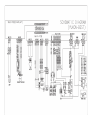
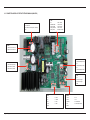
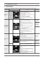
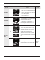
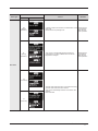
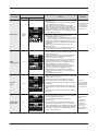
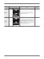
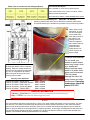
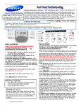
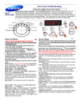
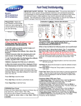
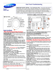
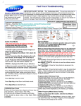
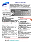
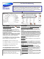
Fast Track Troubleshooting
Model:
WF461ABP/XAA
WF461ABW/XAA
IMPORTANT SAFETY NOTICE – “For Technicians Only” This service data sheet is
intended for use by persons having electrical, electronic, and mechanical experience
and knowledge at a level generally considered acceptable in the appliance repair trade.
Any attempt to repair a major appliance may result in personal injury and property
damage. The manufacturer or seller cannot be responsible, nor assume any liability for
injury or damage of any kind arising from the use of this data sheet.
Revision Date 4-30-2012
Service Mode:
Quick Test Mode
To enter press Spin, Soil, & Power
ously with the power off.
simultane-
1. All LED’s light up and the washer beeps as it
enters the Quick Test Mode.
2. After the displaying the software version, LCD
will display Model information. If EEEE is displayed
the PCB ass’y is defective.
4. When the version is displayed, turn the Jog-Dial
CCW so that the “TST” is displayed. Press the following keys to test the various components:
Press Temp Key to cycle through the Water Valves
circuit test (lock the door first) in this order: Pre-Wash,
Bleach, Cold Main, Hot, & Steam, then off.
Press Spin Key to test Door Lock/Unlock circuit
Press Steam Level Key to test Circulation/Drain Pump.
Press Soil Key to test the Water/Steam Heater.
Press My Cycle to test the Blower motor
When either Test or Spin is displayed on the LCD,
press Start/Pause key to conduct the motor test.
EEPROM Clear Check
Power off, Press Delay Start, Signal and Power Key at
the same time. Good = Good Fail = FAiL
All memory will be cleared, including Fault Codes
This mode allows more detailed operation tests and
troubleshooting, to enter press Signal & Extra Rinse
simultaneously with the power on.
While in Service Mode the following tests can be performed:
Quick Spin Test = Delay Start & Extra Rinse: This accelerates the drum motor from 0 to maximum RPM over a
few minutes. Note: Stay with the washer during this test,
out of balance detection may be bypassed. Press the Start/
Pause button during the test to hold its spinning speed for 10
minutes before going back to Quick Spin Test Mode. Press
and hold the Delay Start & Extra Rinse button to continue.
Cycle Count = Press the Signal button to see how many
times
the unit was used
Soft Ware # = Press the Soil button to see the software version
information
Fault Code Test = Press the Spin button to view the stored
fault codes – then turn Jog Dial to view error codes (Push
Start/Pause while the code is displayed to view the number of
cycles since the error occurred, Push Start/Pause to go back
to faults)
Peripheral (Main PCB) input Tests:
1. Select Extra Wash. Then turn the Jog-Dial so that the
Heavy Duty LED is turned on. Next, press the Start/Pause
Key. The Water Temperature will be displayed in Fahrenheit.
2. Select Extra Wash. Then turn the Jog-Dial so that the
Permanent Press LED is turned on. The door status will be
displayed (OP if open, CL if closed).
3. Select Extra Wash. Then turn the Jog-Dial so that the Sanitize LED is turned on. The door lock Switch status will be displayed (UL if unlocked, Lo if locked).
4. Select Extra Wash. Then turn the Jog-Dial so that the Bedding Plus is turned on. The Water Frequency will be displayed.
6-2. Connector and Relay Port Part Detailed Manual (Main PCB)
► CN10
► CN6
1. AC Power Port
2. Door Detection Sensor(LOCK, UNLOCK)
3. NC
3
1. NC
6. DRY VALVE
2. BUBBLE PUMP
7. PRE VALVE
3. DRAIN_PUMP
8. COOL VALVE
4. DOOR_UNLOCK
9. HOT VALVE
5. DOOR_LOCK
10.BLEACH VALVE
1
► CN7
1
10
5
6
1. Reactor Connection Port
2. Reactor Connection Port
2
1
► CN2
► CN5
1. Motor Power (W Phase)
2. Motor Power (V Phase)
3. Motor Power (U Phase)
1. FAN CONTROL(W Phase)
3
2. NC
1
1
3. FAN CONTROL(V Phase)
5
4. NC
5. FAN CONTROL(U Phase)
1
4
► CN3
1. 5V
2. Hole Sensor Signal
1
9
► CN4
3. Hole Sensor Signal
9
4. GND
► CN10
1. 5V
6. DRST
1. TXD
6. 15V
2. NC
7. FLMD0
2. RXD
7. NC
3. DDI
8. DDO
3. RESET
8. WATER LEVEL
4. DCK
9. GND
4. 5V
9. RELAY WATCHDOG
5. DMS
62 _ PCB Diagram
1
5. GND
4. Troubleshooting
4-1. Error modes
► This is a washer integrated error mode. For detailed information, refer to the general repair scripts.
Error Type
Water Level
Sensor
Motor Driving
Error and Hall
Sensor Error
Water Supply
Error
Drain Error
For USA
LED
461
1E
3E
nF
LCD
Causes
Remarks
- The part of the hose where the water level sensor is
located is damaged (punctured).
- The hose is clogged with foreign material.
- The hose is folded.
- Too much lubricant has been applied to the insertion
part of the air hose.
- Hose engagement error (disengaged)
- Part fault (Faulty internal soldering)
- The water level sensor terminal is disengaged.
- Main PBA fault.
- The PBA connector terminal is not connected.
- The motor spin net is not engaged.
- The motor’s internal coil is damaged (short-circuited
or cut)
- The hall sensor terminal is not connected.
- Foreign material (a screw) has entered the motor.
- Motor overloaded due to too much laundry (Nonsensing)
- The motor hall sensor terminal is not connected.
- PBA fault
- The motor driving error from the PBA is weak.
: Unstable relay operation, etc.
- This occurs due to erroneous operating signals from
the motor hall sensor.
- The IPM terminal of the main PBA is not connected.
- The DD motor cover is out of place.
- The PCB housing terminal is not connected.
- PBA fault
- DD motor fault
This error
occurs because
of restrained
revolutions
This error
occurs when an
interference is
generated due
to too much
laundry, etc.
- Foreign material is entering the water supply valve.
- The water supply valve terminal is not connected.
(Wire disconnected)
- The warm water and rinse connectors are wrongly
connected to each other.
- This occurs if the PCB terminal from the drain hose
to the detergent drawer is not connected. Check
whether the transparent hose is folded or torn.
If this error
occurs in the
Wool course
- The cold and warm water supply hoses are wrongly
engaged into each other.
The water
supplied for 1
minute drying
the drying cycle
is 0.3 ~ 0.4 L.
nF1
- The water temperature is sensed as higher than 50 ˚C
in the Wool or Lingerie or Delicates courses.
nd
- The pump motor impeller is damaged internally.
- The wrong voltage (220 V → 110 V) is supplied to the
parts.
- Part fault
- This occurs due to freezing in the winter season
- The drain hose is clogged. (Injection error, foreign
material)
- Clogged with foreign material
- The water pump terminal is not connected: rubber
band, bills, cotton, hair pins, coins have collected
inside the drain pump ASSY.
Troubleshooting _ 25
Error Type
Power Error
Communication
Error
For USA
LED
LCD
Causes
-
- Check the consumer’s power conditions.
: Make sure to check the operating voltage. Connect
a tester to the internal power terminals during the
Boil or Dry operations and observe the washing
machine’s operation carefully.
: Check the voltages. (An error occurs when under
or over voltage is supplied.)
: Check whether a plug receptacle is used. When
the connecting wire is 1m, a momentary low
voltage may drop up to 10 V
- Main PBA fault (sometimes)
-
- The signals between the sub and main PBAs are not
sensed because of commuication error.
- Check the connector connections between the sub
and main PBAs carefully.
→ Check for incorrect or loose connections, etc.
- Remove the sub PBA C/Panel and check for any
faulty soldering.
E2
- The Power button is pressed continually (for more
than 30 Seconds).
- A switch is jammed or stuck due to be pressed
unevenly due to deformation of the control panel or
button.
- This error may occur when the screws that hold the
sub PBA in place are tightened too much.
- A button other than the Power button is continually
pressed (for more than 30 seconds).
- Deformation of an internal plastic injection part
- A screw for assembling the sub PBA is tightened too
much.
Sr
- The main relay of the PBA is short-circuited.
- The main relay terminal is connected incorrectly.
(The terminal is bent and contact cannot be made.)
Switch Error
(Main Relay
Error)
26 _ Troubleshooting
Remarks
When the
PBA motor
relay does not
operate
Error Type
For USA
LED
LCD
Causes
Remarks
dS
(Before
operation)
- A switch contact error because of a deformation of the
door hook
- When the door is pulled by force
When the door
is not opened
after the door
open operation
dL
(During
operation)
- This occurs in the Boil wash because the door is
pushed due to a pressure difference from internal
temperature changes When the door
is not locked
after the door
close operation
Door Error
LO
(Unlock Fail)
- The door lock switch terminal is connected incorrectly.
- The door lock switch terminal is broken.
- This occurs intermittently because of an electric wire
leakage
- Main PCB fault
FL
(Lock Fail)
Troubleshooting _ 27
Error Type
Heater Error
Water
Leakage Error
Overflow
Error
Temperature
Sensor Error
For USA
LED
Hr
(Heater
Relay)
LCD
Causes
- The washing heater is short-circuited or has a wire
disconnected.
- The washing heater in the tub has an error. (Contact
error, temperature sensor fault)
- If the water level sensor operates without water
because water is frozen or for any other reason and
the temperature sensor engaged at the bottom to
prevent overheating for the washing heater detects a
temperature of 100 to 150 ˚C, the washing machine
turns the input power off.
Remarks
If the heater has
no error, this
occurs because
of a PBA relay
malfunction.
- This error occurs when the red temperature sensor
at the center of the dry heater operates (at a
temperature higher than 145 ˚C)
: Corrective action – Press the button at the center
lightly. The washing machine will operate normally.
Alternatively, replace the temperature sensor if the
temperature sensing is unstable because of functional
degradation.
- This occurs when the steam function does not
operate normally.
- This error does not occur in existing drum products.
Check whether the product is a steam model
LE
- Heater engagement fault (out of place)
- The air hose is out of place and water leakage occurs
during the spin cycle.
- The tub back at the safety bolts fixing part is broken.
- Water leakage occurs at the front with foaming
because of too much detergent
- Water leakage occurs because the connecting hose
to the detergent drawer is connected incorrectly.
- The drain pump filter cover is engaged incorrectly.
- Water leakage occurs at the drain hose.
- The duct condensing holding screws are worn.
- The nozzle-diaphragm is engaged in the opposite
direction or the rubber packaging is omitted.
- Water leakage occurs because the screws that
hold the tub back and front in place are fastened
incorrectly.
- The leakage sensor is faulty.
OE
- Water is supplied continually because the water level
detection does not work.
- Because the drain hose is clogged and there is
an injection error (at a narrow section), the water
level detection does not work and water is supplied
continually.
- Water is supplied continually because of freezing or
because there is foreign material in the water supply
valve.
- This error may occur when the water level sensor is
degraded.
This error
occurs because
the water level
sensor terminal
is out of place.
tE
- The washing heater in the tub has an error. (Contact
error, temperature sensor fault)
- The connector is connected incorrectly or is
disconnected.
- If the water level sensor operates without water
because the water is frozen or for any other reason
and the temperature sensor engaged at the bottom to
prevent overheating for the washing heater detects a
temperature of 100 to 150 ˚C, the washing machine
turns the input power off.
Heater sensor
fault
: When the
connector is
connected
incorrectly or
has a wire
disconnected or
contact error
28 _ Troubleshooting
Error Type
Unbalance
Error
Foaming
Detected
For USA
LED
dc
SUdS
LCD
Causes
Remarks
- As laundry causes this error, check the laundry.
- Find the reason for the unbalance and solve it as
directed in the user manual.
- This occurs when too much foaming is detected. It is
also displayed while foaming is removed. When the
removal is finished, the normal cycle proceeds. “Sud”
or “SUdS” is displayed when too much foaming is
detected and “End” is displayed when the removal of
the foaming is finished.
(This is one of the normal operations. It is an error for
preventing non-sensing faults.)
Troubleshooting _ 29
Water valve connections for the Detergent Drawer
Items Packed With Washer
BOLT-SPANER (10-13mm Wrench) DC60-40146A
ASSY HOSE WATER DC97-15691A and DC97-15692A
MANUAL-BOOK DC68-02535A
CAP-FIXER DC67-00307A HOSE-HANGER DC62-10278A
Stacking Kit :
(Model No : SK-5A/XAA)
Samsung washers and dryers can be stacked to maximize usable space.
An optional stacking kit is available for purchase from your Samsung retailer
When using non-HE
detergents, or using
too much detergent
for the water hardness and soil level of
the clothing, over
sudsing will occur.
When this happens
there will be leaks out
of the detergent
drawer and door.
Please advise consumer of proper detergent usage.
Location considerations
It is normal for some water to remain in
the Detergent Drawer after it completes
washing. Bleach is usually flushed out
into the tub at the beginning of the washing. Also, its compartment is washed
again during the following rinse cycle,
removing any remnants.
Laundry Touch Up Paints
TOUCH UP PAINT, BLUE ONYX
TOUCH UP PAINT, IMPERIAL SILVER
TOUCH UP PAINT, NEAT WHITE
TOUCH UP PAINT, STRATUS GRAY
TOUCH UP PAINT, TANGO RED
DH81-11980A
DH81-11981A
DH81-11982A
DH81-11983A
DH81-11984A
Do not install your
washer in areas where
water may freeze, since
your washer will
always maintain some
water in its water valve,
pump, and hose areas.
This can cause
damage the belts, the
pump, hoses and other
components. Operating
temperature should be
above 60°F/16°C.
SUPPORT INFORMATION
Training — Plus One http://my.plus1solutions.net/clientPortals/samsung/
Help — GSPN http://service.samsungportal.com/
NOTICE
The unit sometimes will pause during Sanitize, or Pure Cycle, wash modes and appear not to be functional. The Sanitize and Pure Cycle wash cycles have target temperatures to assure washer performance. If the water temperature
doesn't meet the target temperature during the wash cycle, the washer will automatically add extra time to allow the
heater to bring the water up to the programmed, or target temperature. In this stage, the displayed time will pause and
hold until the heating operation has been completed. It is at this point that the customer may feel that operation has
stopped. (The maximum added programmed time is 30 minutes)