1
Deployment Guide: Oracle on Microsoft Windows
and the Dell PowerEdge 6850 Server
By: Bryan Thomas and Larry Pedigo
Performance Tuning Corporation
Introduction
Migrating traditional Oracle databases to Oracle Real Application Clusters has become an emerging trend in the IT field. The reasons
are clear: Oracle RAC offers a way to obtain high availability and high performance benefits at a relatively low cost. Dell PowerEdge
servers are one of the most popular platforms for Oracle RACimplementations. Dell is now introducing the PowerEdge 6850 server,
which should soon become the platform of choice for mission-critical Oracle RAC implementations.
Much of the available literature regarding Oracle RAC focuses on Linux and Unix implementations. Nonetheless, Microsoft Windows
Server is one of the most popular platforms for implementing new Oracle databases, and Oracle supports Windows as a
tier-1 platform for development and deployment.
The purpose of this white paper is to identify the issues involved in configuring Oracle RAC on Windows with Dell hardware and to
provide a template for successful implementations. Topics covered include installing the Operating System for Oracle, configuring
the Cluster hardware, installing Oracle software, creating the RAC database, and post-installation tasks. The focus will be on Dell best
practices for Oracle RAC implementations. Dell PowerEdge 6850 servers will be used as an example for RAC
implementation. Both Oracle9i and Oracle10g implementations will be covered.
To get the greatest benefit from this white paper, you should seek the answers to certain key questions before you proceed:
• What applications are going to be connecting to the Oracle RAC cluster?
• Why do you want to deploy Oracle RAC? (high availability?, increased
performance?)
• What is the size of the database?
• How many users are going to be connecting directly to the database?
Answering these key questions will help you to choose among the various installation options presented in this paper, and should
lead to a successful implementation of Oracle on Microsoft Windows and the Dell PowerEdge 6850 server.
Executive Overview
Microsoft Windows Server is one of the most powerful and flexible platforms available for implementing Oracle Real Application
Clusters. Implementing Oracle Database with Real Application Clusters on Windows is a recipe for high availability and scalability on
a low-cost platform. This paper will address implementing this winning combination by providing practical guidelines and examples.
Dell PowerEdge 6850 servers, Intel Xeon 32-bit processors (or Xeon 64-bit processors with the EM64T architecture), and Dell | EMC
storage provide an ideal combination of hardware components for implementing an Oracle RAC database on Windows Server. The
Dell PowerEdge 6850 server adds value by supporting both 32-bit and 64-bit implementations of Oracle RAC. Near linear scalability, a
wide variety of options, and an attractive Total Cost of Ownership make the Dell/Microsoft/Oracle RAC solution an attractive solution
for everything from departmental IT needs to mission critical databases.
Of course, any solution with this much cutting-edge technology is going to have a fair amount of inherent complexity. This can be
discouraging to someone attempting a new Oracle RAC deployment. However, this paper focuses on the areas where IT staff needs
the most help: configuring the cluster hardware, configuring the shared storage, and navigating through the maze of software and
patches that need to be installed. By following this guide, IT staff members will be able to successfully deploy Oracle Real Application
Clusters on Dell hardware and Microsoft Windows Server.
Installing Microsoft Windows Server OS
Let’s begin by introducing some terminology that will be used throughout this paper:
Oracle Enterprise Manager – Management services for the entire Oracle infrastructure. OEM is included with all editions of Oracle Database.
Oracle Real Application Clusters (RAC) – Allows administrators to run Oracle on two or more systems in a cluster while
concurrently accessing a single shared database. This creates a single database system that spans multiple hardware systems, yet
appears to the
application as a single unified database system, extending high availability and broad scalability to applications. Optional for Enterprise Edition, included with Standard Edition.
Database Editions:
Enterprise Edition (9i, 10g; server-side) – For unlimited servers and processors. Optimal scalability and high availability with
Oracle Real Application Clusters option.
Standard Edition (9i, 10g; server-side) – For servers with up to four processors. Includes Oracle Real Application Clusters at
no extra cost.
Automatic Storage Management (ASM) – Manages disk striping and mirroring within Oracle Database 10g. Included with all
editions of Oracle Database.
Data Guard – Allows administrators to set up and maintain a standby copy of their production database to more quickly recover
and maintain continuous database service, even in the event of a disaster. Available with Oracle Database Enterprise or Personal
Editions.
Flashback Query – Allows administrators or users to query any data at some point-intime in the past and can be used to view and
reconstruct lost data that may have been deleted or changed by accident. Included with all editions of Oracle 9i Database and Oracle
Database 10g.
Oracle Data Provider for .NET (ODP.NET) – .NET data provider designed exclusively by and for Oracle for optimal data
access from .NET to Oracle 9i Database and Oracle Database 10g. Can be used from any .NET language, including C# and Visual Basic
.NET.
Microsoft Windows Server offers a powerful platform for deploying an Oracle database, particularly an Oracle RAC database.
Windows Server Editions offer all of the scalability and flexibility that you need for developing a robust production database. The first
step towards building your own RAC database is choosing the right Windows Server Edition.
One of the key differences between Microsoft Windows Server Editions is their support for 32-bit or 64-bit architectures. Almost all
existing Windows databases are currently deployed on 32-bit architectures. Oracle supports Windows 2000 Server (with Service Pack
1 or higher) and Windows Server 2003 in all Editions with the 32-bit versions of Oracle9i and10g. Choosing a 32-bit Windows Sever
Edition can ease the migration from legacy databases and applications.
To make the transition easier, Intel is offering the EM64T architecture to bridge the 32- bit and 64-bit application worlds. The Intel
EM64T processor supports both 32-bit and 64-bit versions of Microsoft Windows Server 2003. In addition, Dell is offering the
PowerEdge 1850, 2850, and 6850 rack-ready servers to take advantage of the Intel EM64T architecture. The PowerEdge 6850 server
is the “flagship” of the Intel EM64Tbased line, offering 4-way scalability and a number of performance improvements over previous
servers. The combination of Intel EM64T processors, Microsoft Windows Server 2003, and the Dell PowerEdge 6850 Server will make
an ideal platform for transitioning to 64-bit databases.
Choosing a 64-bit Windows Server Edition can be beneficial for large databases or data warehouses that have substantial memory
requirements. 64-bit versions of Windows Server natively support large Oracle SGAs without the need for memory extension
techniques. There is no performance penalty for databases with SGAs larger than 3 GB. Many companies are already choosing 64-bit
versions of Microsoft Windows for deploying new mission-critical databases. Microsoft currently offers Windows Server 2003
Enterprise Edition and Datacenter edition for systems with 64-bit Intel Itanium 2 processors. In the near future, Microsoft will offer
64-bit versions for all WindowsServer 2003 Editions for use with the new Intel EM64T processor. One of the advantages of the Intel
EM64T platform is that it will allow a mixture of 32-bit applications and 64-bit applications to run simultaneously under the
upcoming 64-bit version of Microsoft Windows Server 2003. The Dell PowerEdge 6850 server is designed for optimal performance
with the 64-bit EM64T version of Microsoft Windows Server 2003.
Please note that this paper will only cover the installation process for the 32-bit version of Windows. If you plan to install a 64-bit version of Oracle10g, you can use this guide, but be sure to download the 64-bit version of Oracle10g Database (available soon for the
EM64T 64-bit platform).
Preparing Windows Server for Oracle Installation
At first glance, installing the Windows OS prior to deploying an Oracle database may seem to be a relatively simple task. After all,
most of us have some experience with installing Windows Operating Systems. It would seem to be well within our “comfort zone”.
However, preparing the Windows OS for Oracle involves more than simply popping the CD in and clicking through a few menus. One
of the key problems is all of the drivers and hardware support required for an Oracle RAC installation. For example, all RAC
implementations require shared external storage. A variety of BIOS settings, drivers, and support software installations are required
to implement shared storage on a SAN. If any of the software versions are out of synch, the San may simply not function.
One of the best ways to avoid this type of pitfall is to use Dell’s Windows installation media to assist in the installation of Windows
and associated drivers. The Dell Server Assistant CD is perfect for this purpose. This CD will provide a matched set of drivers that will
provide a tested and certified configuration for an Oracle RAC. You simply insert the Dell Server Assistant CD, and then work through
the menu choices. You will then be prompted to insert your Microsoft Windows CDs. The result will be a Windows installation that is
designed to work with all of your hardware.
After the OS installation, there are a few additional steps that need to be performed to prepare for the Oracle installation. The first
step is to ensure that hostnames and IP addresses are resolved for all servers in the RAC cluster. Check that the External/Public Hostnames are defined in your Directory Network Services (DNS) and that the correct IP addresses resolve for all nodes in the cluster. In
addition, you need to define all External/Public and Internal/Private Hostnames in the HOSTS file on all nodes of the cluster. This file
is located in the WINDOWS_HOME\System32\drivers\etc directory.
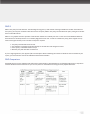
For example, a two node cluster may look like:
For Oracle10g, an extra IP address is necessary for each server for a “virtual” IP address.
The virtual IP addresses should be included in the hosts file and registered in DNS. The
virtual IP addresses should be in the same subnet as the public addresses. An example
hosts file for a10g two node cluster would look like:
Do not assign the Virtual IP addresses to a specific network adapter; Oracle will manage these IP addresses directly and will assign
them to the correct network adapter during Oracle installation. To test host name resolution, open a
command line window and use the “ping” command to check all IP addresses and host names from each host. The
virtual IP addresses will time-out if ping’ed; this is expected behavior. For example:
The order that the server’s NIC cards (and IP addresses) are defined to Windows is important. Windows must recognize the public IP
address as the first address. Otherwise, any Oracle utility that uses “gethostbyname” (such as Oracle
Enterprise Manager) might identify the wrong host. In Windows 2000, to check (and, if necessary, fix) the order that NICs are defined
in:
1. Choose Start -> Settings -> Network and Dial-up Connections.
2. Choose Advanced -> Advanced Settings.
3. Check the order in the Connections field. Click on the Arrow buttons to move the NICs up or down in the list.
4. Click OK when the order is correct.
You will also need to check that the TEMP and TMP host variables are defined properly in Windows. These host variables need to
point to a directory or directories that can be used for temporary files, normally the temporary folders
already defined during installation. To install properly across all nodes, the Oracle Universal Installer will need to use these temporary
folders. The TEMP and TMP folders should be the same across all nodes in the cluster. By default
these settings are defined as %USERPROFILE%\Local Settings\Temp and %USERPROFILE%\Local Settings\Tmp in the Environment
Settings of My Computer. It is recommended to explicitly redefine these as WIN_DRIVE:\temp and WIN_DRIVE:\tmp; for example: C:\
temp and C:\tmp for all nodes. You will need to create these directories manually.
Finally, you should configure the Microsoft Service Distributed Transaction Coordinator to avoid conflict with Oracle patch installation. By default, this service is set to autostart on each boot. MSDTC has been known to interfere with patch installation. To avoid this
problem, set the service to run manually, at least until the Oracle installation is finished. This service may be configured by navigating
to Control Panel -> Administrative Tools -> Services
You may set the service back to automatic startup once the installation is finished.
Configuring the Cluster Hardware
Any implementation of clustered servers is as much about hardware as it is about clustering software. Oracle Real Application
Clusters are no exception to this rule. An Oracle RAC system requires particular hardware components, configured in a particular
way. If the hardware components are missing or mis-configured, there is no chance that the cluster software will ever work properly.
One of the most significant hardware components in an Oracle RAC system is the shared storage. Shared storage is sometimes implemented with external SCSI arrays, direct attached to two clustered servers. More commonly, a shared Storage Area Network (SAN) is
utilized. A SAN is essential for any cluster with more than two nodes.
The sections below will detail the specific Dell hardware components and configuration steps required for a successful Oracle RAC
deployment on Dell hardware and Microsoft Windows Server. Special attention will be given to the requirements for shared storage
and SANs.
Dell Minimum Hardware List and System Requirements
Oracle provides some general guidelines for minimum hardware and software requirements. These include:
• External shared storage
• At least 256 MB of RAM on each node (512 MB preferred)
• Oracle supported clusterware. In Oracle9i, Oracle supports a variety of OS dependent clusterware on different platform However, for Windows Server, Oracle provides the clusterware. For Oracle9i on Windows, Oracle can manage shared storage by
either accessing raw disks, or by using the Oracle Cluster File System (OCFS). For Oracle10g, both raw disks and OCFS are still
supported. In addition, Automatic Storage Management (ASM) offers automated management of shared disks.
Oracle provides a list of certified hardware configurations on the Metalink website, http://metalink.oracle.com.
Dell offers some specific guidelines for implementing Oracle RAC. These guidelines can be viewed on the Dell website, http://www.
dell.com/oracle . The following is a synopsis of the minimum hardware requirements for Dell hardware configured for Oracle RAC:
1. Dell PowerEdge system (two to eight nodes using OCFS or two to four nodes using raw devices).
2. Intel Pentium III processor, 700 MHz or higher
3. 512 MB RAM
4. Integrated SCSI adapter or PERC 3/Dx controller for internal hard drives
5. One 36- or 73-GB hard drive connected to integrated SCSI adapter or two 36- or 73-GB hard drives (RAID 1) connected to a PERC 3/Di controller
6. Two NICs (three for redundant interconnect option)
7. Gigabit Ethernet switch (two for redundant interconnect option)
8. Dell | EMC Fibre Channel external storage option
a. Dell | EMC CXx00 fibre channel storage array with one DPE2 storage processor unit and optional DAE2 disk
expansion units
b. At least three LUNs of 5 GB each
c. Qlogic or Emulex optical HBA (Host Bus Adapter) – two if using PowerPath software
d. Dell | EMC Fibre Channel switch (two if using PowerPath software)
i. Eight ports for two to six nodes
ii. Sixteen ports for seven or eight nodes
iii. No switch is required for the two-node direct attached storage option
e. Fiber optic cables between HBAs and switch ports, and between switches and the CXx00 Storage Processor ports
9. Dell PowerVault SCSI Array external storage option
a. Two nodes only
b. Dell PowerVault 22xS storage system
c. Two enclosure management modules (EMMs)
d. At least one logical drive configured as RAID 0, RAID1, RAID 5 or RAID 10. Dell recommends RAID10.
Cluster Hardware Considerations for Oracle RAC
This section covers some of the issues that you should consider when choosing hardware for your Oracle RAC system. Two of the key
issues are how to choose the right RAID level for your shared storage, and how to choose the right amount of memory for your RAC
servers.
RAID Systems
Managing a large number of individual disk drives can be very difficult, since you must balance the database files across all of these
disk drives in order to spread out the I/O load. In order to simplify this task, provide for optimal performance and to provide a fault
tolerant system, RAID systems were developed. RAID stands for Redundant Array of Inexpensive Disks.
RAID systems are very configurable, depending on what your needs are. These different configurations have different performance
and fault tolerant properties and are known as RAID levels. These RAID levels work differently but essentially serve the same
purpose, to create a logical disk drive out of two or more physical disks. A logical disk drive orlogical volume looks to the operating
system and relational database management system (RDBMS) like a disk drive, but in reality might be the combination of many disk
drives. RAID volumes are combinations of multiple disk drives configured in a RAID array to provide the desired performance and
fault tolerant properties.
RAID 0
RAID 0 is considered a RAID level even though there are no redundant properties associated with this RAID level. A RAID 0 takes a
number of disk drives and stripes them into a larger logical volume. By using RAID 0 you can combine or stripe multiple disk drives
into what appears to the operating system as a single large disk drive. RAID 0 works by taking the data in the logical volume and
striping that data across the array. The data in the logical volume is broken down into what are known as chunks or stripes
(depending on the vendor). These chunks are typically 64K, 32K or configurable in size. The chunks are then allocated to the physical
disk drives in a round-robin fashion.
In an RDBMS environment, it is not recommended to use RAID 0. In the event of a disk failure (and disk failures are probably the
most likely type of failure to occur) all of the data or programs would be lost and you must recover from backup.
RAID 1 and RAID 10
RAID 1 is known as mirroring. With RAID 1 the entire contents of your disk drive has an exact copy on another disk drive, known as
the mirror. With RAID 1 a disk drive failure is transparent to the user. If a disk drive were to fail, the mirrored disk drive immediately
takes over. The term fault tolerance refers to the fact that the system can tolerate a fault, such as the loss of a disk drive and continue
processing seamlessly.
RAID 10 or RAID 0+1 is a combination of RAID 0 and RAID 1. With a RAID 10 configuration disk drives are mirrored and then striped.
Thus you can take advantage of the RAID 0 disk volume where you can increase space and performance as well as taking advantage
of the mirroring properties of RAID 1.
RAID 5
RAID 5 uses parity for fault tolerance. The advantage of using parity is that instead of having to double the number of disk drives in
the system, you only have to add one disk drive to store the parity. RAID 5 uses parity, but distributes the parity among all of the disk
drives in the RAID volume.
RAID 5 is very popular because it provides a fault tolerant solution at a relatively low cost. For the cost of one additional disk drive
fault tolerance is achieved, but this is at a relatively high performance cost. In order to maintain the parity, when a logical write (a
write to the logical volume) occurs a number of steps are required:
1. The parity and data disks must be read.
2. The new data is compared to the data already on the disk drive and changes are noted.
3. A new parity is calculated based on step 2.
4. Both the party and data disks are written to.
So, for a single logical write, four physical I/Os must take place. When calculating the number of disk drives that are needed in your
system, you must take into account the additional overhead due to RAID 5.
RAID Comparison
Each RAID level has its own attributes and performance characteristics as described above. The following table shows a comparison
of those attributes and characteristics. As you can see, there are vast differences among the most popular RAID levels.
Recommendations for Oracle Component Placement
Oracle is sensitive to read performance and sensitive to write performance on the redo log files and on the archive log files. Thus, the
following recommendations are given.
OS Volume - The OS should be installed on a RAID 1 disk volume. It is important that you do not need to restore/rebuild the OS in
the event of a disk failure. This can be very time consuming and expensive. The OS will certainly fit on one disk drive, and RAID 5 is
generally not supported in a 2 drive configuration. In addition, the Oracle binary files can be placed on this volume.
Redo Log Files - The Redo Log files should be placed on a RAID 1 or RAID 10 volume. The I/Os to the Redo Log files are 100% sequential and 100% writes, thus RAID 5 is inappropriate.
Data Files - The Data files should be RAID 10 if the I/Os are 90% reads or less. If the I/O pattern is 90% or greater reads, then RAID
5 is OK. Again, your budget may help determine this.
Archive Log Files - The Archive Log files can either be RAID 10 or RAID 5, depending on your budget. Archiving might take longer
if it is RAID 5.
By using RAID fault tolerant volumes, much pain and expense can be avoided in the event of a disk failure.
Configuring Server Memory
One of the challenges in configuring Oracle databases on Microsoft Windows is in choosing the appropriate amount of RAM. This is
particularly true on 32-bit implementations of Microsoft Windows, such as Windows Server 2000 and the 32-bit version of Windows
Server 2003. Due to inherent limitations in the 32-bit architecture, it is not possible to access more than 4 GB of memory in a single
memory segment. This places some limitations on Oracle SGA (System Global Area) size. By default, Oracle SGA sizes are limited to
2 GB or less. On Windows an Oracle instance runs as a single process. This process is a standard Win32 application that is able to
make memory allocations from the 2GB virtual address space. All memory allocations made by all user connections and background
threads have to fit into 2GBs including global allocations such as the buffer cache. For systems that have either large user populations
or buffer cache requirements this presents a problem.
Large Memory Implementation
Some help may be obtained by utilizing a feature known as 4 GB RAM Tuning (4GT). By setting the /3GB flag in the Windows boot.ini
file, Oracle SGA sizes up to 3 GB are supported. The OS and all other processes must use the remaining 1 GB of usable memory.
Another technique is available to address memory above 4 GB. The Address Windowing Extensions interface (AWE) allows access to
RAM up to 64 GB. AWE is implemented through Physical Address Extensions, which are enabled by setting the /PAE flag in the boot.
ini file. In addition, the account that runs Oracle must have the “Lock memory” privilege set under Local Security. The “USE_INDIRECT_BUFFERS=TRUE” must also be set in the Oracle initialization file. Another initialization parameter requirement is that the DB_
BLOCK BUFFERS parameter should be used instead of the DB_CACHE parameter. Note that only the buffer cache may be extended
above 4 GB. The rest of the SGA must fit below 4 GB.
The AWE interface is supported by both Microsoft and Oracle. However, there is some performance overhead associated with AWE.
In performance testing on 32-bit Windows systems, it has been noted that there is minimal performance gain when the Oracle SGA
size is increased above 4 GB all the way up to 8 GB. Above 8GB, performance gains are more noticeable.
There is another “hidden” catch to using AWE memory. There is a registry parameter called AWE_MEMORY_WINDOW. This
parameter specifies a window contained within the first the first 4 GB of memory that is used as a “swap” space for mapping upper
memory buffers. The default window size is 1 GB, but the size may be customized by explicitly setting the registry key. Every block
of high memory used must first be temporarily copied to this scratch space. The larger this window (i.e. 1.25 GB), the higher the
efficiency of the copy operation, and the higher the performance. However, the ability to support large numbers of users will suffer,
even with the use of Shared Server connections. This is because the entire Shared Pool, Large Pool, and PGA must fit in the space
under 4GB that is left after subtracting the AWE_MEMORY_WINDOW. With a default AWE_MEMORY_WINDOW of 1 GB, this leaves
only 1 GB of memory available for supporting user connections. Some relief is offered by reducing AWE_MEMORY_WINDOW to 0.75
GB. However, this will allow only a few hundred users to log on simultaneously. For large user populations, the /3GB flag will have to
be
set in the boot.ini file as well as the /AWE flag. This frees up an extra 1 GB of memory for the Shared Pool, Large Pool, and PGA,
allowing more user connections. Unfortunately, there is a downside. With the /3GB flag set, it is impossible to access over 16 GB of
RAM. Any additional RAM would be inaccessible.
Due to these issues, the following are best practices for choosing server memory for Oracle implementations on Windows. For
optimal performance on 32-bit systems, it is recommended to use 4 GB of RAM and a max SGA size of 3 GB. If you need a larger
amount of memory, it is recommended to use more than 8 GB of RAM. However, if you utilize a 64-bit version of Windows (Windows
Server 2003 Enterprise and Datacenter) and a 64-bit version of Oracle software, you can use up to 16, 32, or 64 GB of RAM, depending on the Dell server chosen. The Dell PowerEdge 6850 server may utilize up to 64 GB of RAM, with 4 GB memory per slot.
Changes in Memory Requirements for RAC
When moving from a single node database to a RAC database, there are some changes in memory requirements. If you are keeping
the workload requirements per instance the same, then about 10% more buffer cache and 15% more shared pool is required. The
additional memory requirement is due to data structures for coherency management. The values are heuristic and are mostly upper
bounds. Actual resource usage can be monitored by querying current and maximum columns for the gcs resource/locks and ges
resource/locks entries in V$RESOURCE_LIMIT.
But in general, please take into consideration that memory requirements per instance are reduced when the same user population is
distributed over multiple nodes. In this case:
Assuming the same user population N number of nodes M buffer cache for a single system then
(M / N) + ((M / N )*0.10) [ + extra memory to compensate for failed-over users ]
Thus for example with a M=2G & N=2 & no extra memory for failed-over users
=( 2G / 2 ) + (( 2G / 2 )) *0.10
=1G + 100M
Features of the Dell PowerEdge 6850 Server
The PowerEdge 6850 is a 4U rack mountable server that provides an update to the popular PowerEdge 6650 server. The PowerEdge
6850 takes full advantage of all of the features of the Intel EM64T architecture. It functions equally well as a 32-bit server or as a 64bit server. In addition, the PowerEdge 6850 server has a number of new features that benefit Oracle RAC implementations.
Performance Enhancements
The PowerEdge 6850 server contains a number of performance enhancements that extend
the features of the PowerEdge 6650.
• The PowerEdge 6850 server is available with 2-4 Xeon EM64T processors, compared to the Xeon 32-bit processors
previously available for the PowerEdge6650
o Processors are available with clock speeds in the range of 3.0 GHZ – 3.6 GHz, compared to a maximum of 3.0 GHz previously available
• Contains a 667 MHz front-side bus, compared to a 400 MHz front-side bus previously available
• Utilizes 256 MB – 64 GB DDR-2 400 GHz memory, compared to the 200 MHz DDR memory previously available
• 4 PCI-Express slots
• Perc4eDC-PCI Express primary and secondary controllers are available
• 32-bit and 64-bit OS availability
o Windows 2003 Server, Standard, Enterprise, or Web Edition (32-bit)
o Many other OS options
Reliability, Availability and Serviceability Features
The Dell PowerEdge 6850 server is designed from top to bottom for High Availability. There are a number of features of the PowerEdge 6850 server that enhance Reliability, Availability and Serviceability.
• Available with Dell Remote Access card 4 for remote management
• Redundant power supplies
• Dual on-board Broadcom NICs (available for network teaming)
• Embedded RAID support (ROMB)
• Up to 5 Ultra 320 SCSI internal hard drives for RAID reliability
o 18-300 GB disks
o 10K or 15K rotational speeds
• Support for High Availability Storage
o PCI-Express Fibre Host Bus Adapters for Dell/EMC SAN connectivity
o Connectivity with Dell PowerVault tape libraries
o Tape backup software from Veritas, CommVault and TapeWare
Intel EM64T Implementation on the Dell PowerEdge 6850
Dell PowerEdge 6850 servers are designed to fully exploit the latest Intel EM64T technology. The Intel Xeon EM64T processor and
Intel 7520 chipset contain a variety of new features and improvements over existing Xeon features. One of the key improvements is
a large addressable memory space, up to 1 TB in the current release. The processor utilizes an increased number of registers, with
increased width for each register. Level 2 cache size has been increased to 1 MB, four times as big as previous Xeon chips used on the
PowerEdge 6650. Increased cache size is a big advantage, because it brings data closer to the CPU for faster access, and increased
memory caching leads to reduced I/O. The EM64T processor also features hyperthreading performance improvements, which can
increase parallelism for processing. The Intel 7520 chipset contained on the PowerEdge 6850 supports up to an 800 MHz Front Side
Bus, while previous chipsets supported only up to 533 MHz.
One of the key performance advantages of the Intel EM64T architecture on the PowerEdge 6850 server is the use of DDR-2 memory.
DDR-2 memory is configured with higher density than DDR memory, enabling greater memory scalability. CCR-2 memory runs at 400
MHz, twice as fast as DDR memory. DDR-2 also consumes less power – it runs at 1.8V versus DDR which runs at 2.5V.
The Dell PowerEdge 6850 server features four PCI-Express slots. PCI-Express helps move data faster between processors and
memory, helping to speed up processing tasks - especially for memory-intensive applications like databases. PCI Express is capable of
delivering three to four times the throughput of PCI-X, up to 64Gb/s of throughput. PCI Express technology is natively hot-pluggable,
and doesn’t require driver installation for PCI-Express device recognition. One of the main benefits of PCI-Express is that it enables
faster device driver performance.
The Dell PowerEdge 6850 server is capable of running in several different modes, due to the EM64T processor. There two major
modes: IA32e mode and Legacy mode. IA32e mode is automatically invoked when a 64-bit OS is booted. Legacy mode is
automatically invoked when either a 32-bit OS or 16-bit OS is booted.
IA32e mode is based on the existing IA32 mode, with 64-bit extensions. Under IA32e mode, two different sub-modes exist: 64-bit
mode and Compatibility mode. Both modes require that a 64-bit OS is booted, such as Windows Server 2003 64-bit for EM64T. 64bit mode takes advantage of the full register width. Up to 1 TB of memory is addressable, without the need for AWE memory. Compatibility mode is automatically invoked for 32-bit applications, on a per code segment basis. This means that if you boot
the Dell PowerEdge 6850 server with Microsoft Windows Server 2003 64-bit EM64T version of the OS, you can run a mix of 32-bit
and 64-bit applications without compromising performance. Of course, applications that run in 32-bit mode still access memory
above 4 GB with the AWE model, but the first 4 GB is available without any OS overhead, which is an improvement over the standard
32-bit model.
Legacy mode is essentially the same as the existing IA32 model. It contains three submodes: Protected mode, Virtual-8986 mode,
and Real mode. Real mode and Virtual-8986 mode are both used for 16-bit applications, and are used rarely. Under Legacy mode, the
most commonly used sub-mode will be Protected mode. It is automatically invoked when a 32-bit application runs on a 32-bit OS.
With Protected mode, you can run a 32-bit OS, such as Windows Server 2003 with no negative performance impact. This is the mode
used in the RAC installation example used in this paper. In Protected mode, memory access uses the 32-bit AWE model, with
behavior unchanged from previous Dell PowerEdge servers.
Impact of the Dell PowerEdge 6850 on RAC Implementations
One of the main motivations in moving to Real Application Clusters is to implement a High Availability infrastructure. Therefore, it
makes sense that an HA infrastructure should be composed of high quality components, with built-in internal redundancy and
reliability. The PowerEdge 6850 offers the highest level of RAS features available, and will make the ideal building block for a High
Availability RAC infrastructure. RAC is often implemented to “scale out” for performance increases, as opposed to “scaling up”. With
the PowerEdge 6850, companies have the ability to scale up and scale out at the same time. As a RAC node, a single 6850 will
support large numbers of users and large workloads, due to the 4 processors and up to 64 GB of RAM. With up to eight nodes
supported in RAC configurations, the PowerEdge 6850 is capable of supporting any Mission-Critical Enterprise workload with
outstanding performance.
The Dell PowerEdge 6850 Server with the Intel EM64T processor has the advantage of working equally well in 32-bit mode and 64-bit
mode. As Microsoft Windows 2003 Server for EM64T and 64-bit Oracle RAC for EM64T become available, the 6850 server will offer
the perfect route to transition to 64-bit RAC. In addition, the price/performance ratio is particularly attractive for a 64-bit server,
which is all the more important when multiplied by multiple RAC nodes.
Installing and Configuring the Dell | EMC SAN
or PowerVault Shared Disk Array
Installing and configuring a Dell | EMC SAN is a discipline unto itself. It requires training and specific storage domain knowledge. Fortunately, most of the “heavy lifting” is usually performed by Dell Professional Services. After the initial configuration, management
becomes much more straightforward, and it is relatively easy to manage these storage arrays with the Navisphere Manager interface.
In addition, simple web interfaces are available for managing Dell | EMC Fibre Channel switches.
Dell | EMC Fibre Channel Storage Installation Steps
Even if your fibre channel storage array is configured by Dell Professional Services, it is important to understand the overall
installation and configuration process. Below is an overview of the key steps:
• Initial hardware setup – this includes placing hardware in racks, connecting cables between components, and powering up the storage array
• Install Host Bus Adapters in the PowerEdge 6850 servers
o Two HBAs are required for high availability
o Both PCI-Express and PCI-X versions are available
o Be sure to use slots with the same PCI version and bus speed for both HBAs on each cluster server (there is a diagram of slots on the top inside cover of the 6850).
• Initialize the CXx00 array – This involves accessing the storage array through a serial connection or cross-over cable, and setting key parameters. In addition, any required array based software is installed or upgraded at this time.
• Install host based software –
o Qlogic/Emulex HBA drivers - In addition to installing the correct version of the HBA driver, it is important to
update the Qlogic or Emulex system BIOS to the currently supported level.
o Navisphere Agent – this host-based agent will be used to register connected hosts with the storage array.
o PowerPath – this software is used to configure failover and load balancing between fibre channel connections on a given server.
• Set up networking – In addition to configuring public network access for cluster servers, you must also connect the storage array to the network. Theseconnections allow server discovery by the storage array.
• Configure Fibre Channel switches – this step involves connecting to the switches via a serial or web interface. Initial
configuration is performed, in preparation for zoning.
• Perform Zoning on Fibre Channel switches – Zoning is the process of mapping servers to the storage array and granting specific access right to servers
• Configure storage with Navisphere – these are the key steps for organizing and presenting storage to the servers. Included are:
o Create RAID groups from sets of disks
o Subdivide the RAID groups into logical disk units called LUNs
o Create a storage group that includes the servers and LUNs for the Oracle RAC system. The components of this storage group will be allowed to connect to each other.
• Access storage through each server in the cluster – all servers should now have the same view of the shared external
storage. PowerPath software adds value by managing multiple connections to the storage array per server for path failover and load balancing.
For a two-node cluster, you may directly attach to a CXx00 storage array with fiber cables rather than using a switch. This requires at
least two HBAs and associated cables per server. In addition, PowerPath software is required for these implementations.
Dell PowerVault Installation Steps
A more common option for Direct Attached Storage on two-node clusters is a Dell PowerVault 22xS SCSI storage array. This provides a
relatively low-cost option for simple clusters. Setting up PowerVault arrays is much easier than setting up a SAN:
1. Set both EMMs to Cluster Mode on the PowerVault array
2. Restart the first node
3. Set RAID controller on first node to SCSI ID 6
4. Use <ctrl> <m> during the RAID controllers boot to start the RAID controller configuration
5. Set the first RAID controller to Cluster Mode
6. Create at least three LUNs of 5 GB from the first node
7. Restart the first node
8. Restart the second node
9. Use <ctrl> <m> during the RAID controllers boot to start the RAID controller configuration
10. Set RAID controller on second node to SCSI ID 7
11. Set the second RAID controller to Cluster Mode
12. Verify that the second RAID controller can see the same LUNs
13. Restart the second node
Best Practices for Storage Configuration
RAID Configuration - RAID 1 or RAID 10 is recommended for all database components. The use of RAID 5 in an Oracle environment is discouraged because of the performance penalties incurred by the parity computation.
Minimal LUNs - The minimal number of LUNs required for a RAC cluster is one redo LUN per node, one LUN for archive log files,
one LUN for data files and one LUN for quorum. LUNs = quorum + (# of nodes) + data + archive
Best Practice LUNs - The best practice number of LUNs for a RAC cluster is two LUNs per node for redo, one LUN per node for
archive, one or more LUNs for data files and one LUN for quorum. LUNs = quorum + (2 x # of nodes) + (one ore more data) + (# nodes
for archive)
LUN RAID Groups - For highest performance and deterministic response time assign only one LUN per RAID group.
LUN RAID Groups - For optimal performance, assign 8-10 drives per RAID 10 RAID group and 5 or 9 drives per RAID 5 RAID group.
Minimal Disk Spindles - A minimum of 10 disk drives per node should be used (not including hot spares).
Component Placement - Redo log files, database files and archive log files should be separated into different physical disk
groups. In the event of a hardware failure, the system can be fully recovered with any two of these components.
Oracle10g and ASM
All of the recommendations listed above apply to Oracle9i or Oracle10g utilizing the Oracle Cluster File System. However, if the
Automatic Storage Management option is used for Oracle10g, the rules may need to be modified. With ASM, Oracle software can
take on the responsibility for managing disk mirroring and striping. You could go as far as giving Oracle a group of individual raw disks
without any hardware RAID. In this case, Oracle ASM could provide software-based mirroring and striping.
You can specify how many disks that you want to include in the ASM group and the desired level of redundancy (disk mirroring). The
redundancy level can be set at Normal (two-way disk mirrors), High (three-way disk mirroring), or External Redundancy (rely on
hardware disk mirroring). For Dell external storage arrays, it is recommended that you choose External Redundancy. This is
recommended because hardware mirroring is generally more efficient than software mirroring, and puts less load on the servers.
The algorithm used for software striping in ASM is somewhat unique. Striping is handled on a per file basis, so that each table, redo
log, etc. may be striped across a different number of disks. While software-based disk striping is inherently less efficient than
hardware-based disk striping, the sophistication of the automated striping algorithm makes ASM worth checking out. If you are going
to use ASM striping, you should provide multiple small RAID groups. These groups can be RAID 1 disk pairs, or small RAID 5 or RAID
10 groups. For optimal performance with ASM, configure multiple small RAID 10 groups (such as four disk groups). This provides ASM
striping across hardware striped groups, for a “stripe on stripe” configuration.
Field experience has shown that ASM can offer good performance, if the disk array is large enough. The software striping algorithms
tend to work best with the availability of sixteen or more disks in the ASM group. For installations with less than sixteen disks
(counting only the disks assigned to ASM), the Oracle Cluster File System may offer relatively better performance.
Although ASM may or may not be beneficial to performance in individual cases, it is important to remember that performance is not
the main focus of ASM. ASM is designed to simplify Database Administration. With ASM, the DBA no longer has to worry about
how to layout Oracle data. Oracle ASM software automates the process of data placement.
ASM will provide the greatest benefit to companies with less experienced DBA staff or limited DBA staff. Some experienced DBAs may
prefer to manage disk striping and redundancy without ASM. The real benefit of ASM is giving companies the choice to completely
automate storage management or to manually control storage as they desire.
Setting Up Networking
As seen above, you must set up access to the public LAN through one of the NIC cards on each server before you can fully complete
the cluster setup. This is easily accomplished through setting TCP/IP options in the Windows Network Settings interface. Be sure to
check Windows Network Properties to ensure that the Public IP is listed at the top. The Private NIC(s) should always be listed below
the public IP. To check, run the following command to verify that the public IP address is listed first:
It is even more important to properly configure the private network. The private network is used as an interconnect between each
cluster node. This network consists of Ethernet cables and one or more network switches. The major role of the private interconnect
is to implement Oracle’s “cache fusion” technology. This is not a simple heartbeat mechanism, as in other types of clusters. Instead,
Oracle creates a “virtual” image of all of the memory across the cluster by sharing information across the interconnects. Multiple
interconnects per server are desired for high availability, as well as for increased performance.
For performance reasons, all private interconnect components should be capable of supporting Gigabit Ethernet (Gig-E) speeds. At
least one Gig-E switch is required, but two switches are preferred for a high availability solution. A switch is required even for a two
node RAC system. It is not recommended to use a cross-over cable between two servers in lieu of a switch. This is because a failover
event could cause NIC cards connected to a cross-over cable to “freeze”. This problem is avoided when at least one switch is placed
between servers.
Dell offers a variety of PowerConnect network switches that can be utilized for the private interconnect network for Oracle RAC servers. Gig-E capable switches include the PowerConnect 2000, 5000, and 6000 series. They offer from eight to 24 usable ports.
A minimal configuration of the private interconnect network consists of the following components:
1. One gig-e NIC per server
2. One gig-e switch
3. Cat5e or cat 6 cables from NICs to switch
The preferred configuration of the private network includes the following components:
1. Two gig-e NICs per server
2. Software NIC teaming interface on each server
3. Cat 5e or cat 6 cables from NICs to switch
4. Two or more cat 5e or cat 6 cables between switches (crossover or patch)
The preferred configuration offers high availability and increased performance. To complete the high availability configuration, it is
necessary to configure some version of NIC teaming. A teaming interface substitutes a virtual device (the “team”) for the individual
NIC interfaces. The teamed interface will stay available, even if one of the member NICs or Ethernet cables fails.
The Dell PowerEdge 6850 server offers two NIC ports built into the motherboard. These may be used for the public LAN and/or the
private interconnect. Many customers choose to team the on-board ports for the private interconnect. In addition, Broadcom and
Intel add-on NIC cards are available in both PCI-Express and PCI-X versions. Be careful that the slots you choose for add-on NICs are
using the same version of PCI and run at the same bus speed. The inside top cover of the 6850 contains a diagram of the available
slots and configurations.
To configure Broadcom NIC teaming, first install the Management Apps Control Suite. Alternatively, you may use a silent install to
create the team. Set up the IP address for the team as if it were an actual NIC.
If you choose to utilize Intel NICs for teaming, perform the following configuration steps:
1. Install Intel PROSet II (if necessary)
2. Start Intel PROSet II as described in Using PROSet II
3. Run the Teaming Wizard to add adapters to each team.
4. See the PROSet II Help for additional information.
Be aware that Oracle 10g requires the user to select the correct network interface during installation of the database software. With
multiple adapters, the user must select from several interface names in step 5 under the “Cluster Ready Services Installation Steps.”
The default adapter names do not provide the user with enough information to easily identify the public and private adapters. We
suggest renaming the network interface names to indicate there use in the system. For example, public adapter “Local Connection 1”
should be renamed to “Public” and the private interconnect adapter renamed to “Private”.
Note: This must be done on all nodes in the cluster, and the names must not contain the “.” (period) character. The adapter names
MUST be identical and the same case.
Verifying that the SAN is Ready for Oracle
Before proceeding further, you should perform some verification tests to verify that the cluster hardware is ready for Oracle. The first
test checks access to all nodes through the Windows OS. It should be performed for both Oracle9i and Oracle10g installations. To
test, login with a domain administrator account (the Oracle installation account). From each node, check administrative access to all
other nodes with:
(Assuming C is the install drive.) If you do not get a successful result, you should check your networking and permission settings
carefully.
An additional test is available for Oracle9i only. To run this test, download Oracle Patch 3483924 from Oracle Metalink. Extract the
files and place them in a WINDRIVE:\\Disk1 staging directory. Next, run the clusterchek.exe command:
After the test is completed, check the OraInfoCoord.log file in the TEMP or TMP directory for “ORACLE CLUSTER CHECK WAS
SUCCESSFUL”. If you don’t receive a success message, check your storage and networking components carefully.
For both Oracle9i and Oracle10g, a final check is provided by the ability to view shared disks from all nodes. If shared disks are not
identically visible on all nodes, there is a problem with your cluster hardware setup. Configuring shared disks is also necessary as a
pre-installation step.
To configure shared disks, do the following:
1. On the first node only, log in to windows as the Local Administrator.
2. Navigate to Start -> Administrative Tools -> Computer Management.
3. Expand the Storage folder to Disk management.
4. Right-click the unallocated region of a basic disk and choose Create Partition (dynamic disks are not supported).
5. In the Create Partition wizard, choose Next -> Extended Partition (Primary partitions are not supported for Logical Drives).
6. Choose Extended Partition. Choose Next.
7. Choose the maximum amount of available space and choose Next.
8. Choose Finish in the summary screen.
9. The Extended Partition should appear green. Right click on the Extended Partition, and choose Create Logical Drive.
10. Proceed through the Wizard instructions, making sure you choose the entire partition for the Logical Drive. Make sure that you do not assign a drive letter, and do not format the drive. Choose Finish to exit.
11. Reboot the first node. Re-enter Disk Management, and check that no drive letter has been assigned. If a drive letter was assigned, you will have to remove it here (you may also use the Oracle “letterdelete” command from the command line).
12. Reboot each of the other nodes, and check that the drive is visible. Make sure that
no drive letter is assigned on any node. Delete the drive letter, if necessary.
You will need a minimum of three logical drives of 5 GB each for OCFS. If you choose to install Oracle binaries on a shared ORACLE_
HOME, you will need an additional logical drive of at least 5 GB size. For Oracle10g using ASM, you will need one partition of at least
20 MB for the voting disk and one partition of at least 100 MB for the OCR. In addition, for Oracle10g, you may wish to add at least
two more logical drives; one for shared executables (ASM or OCFS) and one for a Recovery Area. Please note that with Oracle10g
using ASM you may place Oracle executables on a shared drive. The Recovery Area should be sized at least as big as 3 GB.
For both Oracle9i and Oracle10g, you have the option of installing Oracle binaries into a shared ORACLE_HOME. For Oracle9i, you
may use OCFS for shared ORACLE_HOME storage. For Oracle10g, either OCFS or ASM may be used for shared ORACLE_HOME
storage. (Note that the CRS_HOME for Oracle10g cannot be placed on an OCFS volume. It may be placed on local directories that are
replicated to each node.) Using a shared ORACLE_HOME eases administration by requiring upgrades or patches in only one location.
Disk space is also saved. In addition, using a shared ORACLE_HOME removes the possibility of Oracle binaries falling out of synch
between nodes. However, there is an advantage to maintaining per-node copies of the Oracle binaries. This practice allows offline
maintenance of Oracle binaries on each individual node while the other nodes remain online, without interrupting users. Even if you
elect to use local ORACLE_HOME directories, you have the option of using the Oracle Universal Installer to replicate binaries to all
cluster nodes, again reducing the chance of binaries being out of synch between nodes.
If you elect to use a Recovery Area for Oracle10g (this is an option, not a requirement), you should be fully aware of the storage
requirements. The purpose of the Recovery Area is to offer a fast disk-based mechanism for recovery. The Recovery Area utilizes a
combination of an RMAN backup to disk and Flash Recovery logs. The initial full RMAN backup and at least one days worth of Flash
Recovery logs guarantees that you will need a Recovery Area at least as large as the sum of the sizes of all the database files. If you
use the default retention period for Flash Recovery logs of seven days, you will need at least 2X the size of the database files. 3X the
size of the database files is not an uncommon scenario. Use of the Recovery Area offers unprecedented recovery speed and
flexibility, but the price you should be prepared to pay is increased disk storage requirements.
Shared Disk Configuration
On windows 2003 (32 and 64 bit versions), the user must enable the automatic mounting
of new volumes on each node in the cluster.
• The default value for auto mounting was changed from enabled in Windows 2000 to disabled in Windows 2003, so this additional step is required.
• Auto mount should be enabled before creating the new partitions and must be done on all nodes in the cluster. A reboot is required for the value to take hold.
diskpart.exe
diskpart> automount enable
diskpart> exit
Install Cluster Software
Both Oracle9i RAC and Oracle10g RAC are offered on a variety of platforms. On each platform, some form of Cluster Software must
be provided in order to utilize shared disks in an active/active mode. Under Oracle9i, Oracle utilizes the native cluster support
available for the particular platform, if available. Under Oracle10g, Oracle has made an effort to provide common Cluster Software
support across all platforms. This provides a consistent experience across all platforms, and makes support easier for both Oracle and
the customer.
For all versions of Windows Server, Oracle has provided the Cluster software since the beginning of Oracle RAC. The actual
installation process used for Oracle Clusterware is somewhat dependent on the method chosen for storing data on shared disks.
With Oracle9i RAC or10g RAC, you always have the option of using Raw partitions for storing shared cluster data. However, it is very
difficult to install on Raw volumes, and even more difficult to administer or back up. For these reasons, installing on raw
volumes is not covered in this paper. The preferred option for Oracle9i is to utilize the Oracle Cluster File System. OCFS offers similar
performance to raw disk partitions, and is almost as easy to manage as a traditional file system. With Oracle10g, you can still
choose to use OCFS. However, you also have the option of using Automatic Storage Management (ASM). ASM can be used with
either stand-alone servers or clustered servers.
The following section details the steps necessary to install Cluster Software. Installing Oracle Clusterware for use with OCFS is covered
for Oracle9i. For Oracle10g installations, installing Cluster Ready Services for use with either OCFS or ASM is covered.
Installing Oracle9i Clusterware
Due to the need to install multiple patches, installing Oracle9i Clusterware is a multi-step process. As a first step, all of the patches
need to be downloaded into a staging directory. Next, the 9.2.0.5 version of the Oracle Cluster Wizard is run to initialize the cluster.
Before proceeding further, it is necessary to upgrade the Oracle Universal Installer (OUI) to version 9.2.0.5. Then you may install OCFS
binaries into the Oracle Home directory.
Note: As of October 2004, the 9.2.0.6 patchset is available for Windows. However, the 9.2.0.6 clusterware patch is not yet available
as of this publication. In the interest of offering a fully tested RAC configuration, this paper will cover a consistent upgrade to all
9.2.0.5 components. Those wishing to upgrade the database components to 9.2.0.6 instead of 9.2.0.5 should read the release notes
for the 9.2.0.6 patchset for exceptions to this procedure.
If you designate local ORACLE_HOME directories on each node, the issue of synchronizing Oracle binary installation on each node
must be addressed. Since cluster member nodes are identified to Oracle early in the installation process, the Oracle installation
process should be able to propagate all required binaries to all cluster nodes, requiring only installation from one node. This works
well for a two node cluster. However, some problems are occasionally experienced when installing on three or more nodes. For this
reason, if you are installing on three or more nodes, you may want to install on each node individually, for the particular steps noted
in the installation instructions below. The processes for installing from either one node or for installing on each node separately are
included in the instructions.
Staging Oracle Patches
As a first step, you will want to create a staging directory to contain the Oracle binary files and patches. It is recommended to locate
the staging directory on an internal directory on the first server. For example:
E:\oracle_stage
For a two-node install with local ORACLE_HOME directories, most files will be copied to the other node by the Oracle install process.
You will still have to copy some patch files manually to all nodes. For three or more node installs, you may want to copy all of the files
to each server. If you use a shared ORACLE_HOME, you can avoid this issue. Regardless of whether the software files will be local or
shared, you might as well download all of the required files and patches to the staging directory at this point, as long as you have
sufficient room. This includes:
1. Copy the three Oracle 9.2.0.1 CD data files to disk in the following example locations:
a. E:\oracle_stage\9201\Disk1
b. E:\oracle_stage\9201\Disk2
c. E:\oracle_stage\9201\Disk3
2. Download the Oracle 9.2.0.5 patch from Oracle Metalink (patch number 3501955) to the following example location:
a. E:\oracle_stage\9205\
b. Expand the patch to create the directory E:\oracle_stage\9205\Disk1
3. Download the Oracle CFS and Clusterware patch 9205 from Oracle Metalink (patch number 3483924) to the following example location:
a. E:\oracle_stage\ocfs9205
b. Expand the patch to create the directory E:\oracle_stage\ocfs9205\3575688 (the Oracle internal number for the
patch)
4. Download the Oracle Universal Installer 2.2.0.18 from Oracle Metalink (patch number 2878462) to the following example location:
a. E:\oracle_stage\oui22018
b. Expand the patch to create the directory E:\oracle_stage\oui22018\Disk1
Run the 9.2.0.5 Cluster Setup Wizard
You are now ready to run the first step in the install process. Since this step does not use the Oracle Universal Installer, you may
install from one node without difficulty. You have the option of choosing a shared directory for software installation or local
directories. If local directories are chosen, the Cluster Setup wizard will automaticallycopy the files to all other nodes. Use the
following procedure:
1. Open a command prompt window.
2. In the command prompt window, navigate to the E:\oracle_stage\ocfs9205\3575688\preinstall_rac\clustersetup
directory.
3. Enter “clustersetup” to start the Oracle Cluster Wizard.
4. Click “Next” in the Welcome page.
5. The only option available on a fresh install is to “Create a cluster”. Click “Next”.
6. Choose the “Use private network for interconnect” option and click “Next”.
7. In the Network Configuration page, enter the following:
a. Enter the cluster name.
b. Enter the public hostnames for all nodes. Enter the private hostnames for all nodes.
c. Click “Next”.
8. In the Cluster File System Options page, choose “CFS for Datafiles only” if you want to use separate ORACLE_HOME
directories on each node. If you want to use a shared ORACLE_HOME, choose “CFS for Oracle Home and Datafiles”. Click “Next”.
9. If you chose “CFS for Oracle Home and Datafiles”, you will see the “CFS for Oracle Home” page. choose a drive letter, and then choose a partition. Make sure it is at least 4.0 GB in size.
10. In the “CFS for Datafiles” page, choose a drive letter, and then choose a partition. Make sure it is at least .0 GB in size. Click “Next”.
11. In the VIA Detection screen, choose “no”. Dell uses gigabit Ethernet as the interconnect mechanism. Click “Next”.
12. In the “Install Location” screen, accept the default of the WIN_HOME\system32\osd9i directory. Click “Finish”.
You may track the installation progress in the Cluster Setup window. The Wizard closes automatically if the installation completes
without error. To verify a successful installation, use the Disk Manger Administrative tool to view the OCFS drive(s). The OCFS drive(s)
should be visible from all nodes. In addition, you should use the Services tool to check that the following three services are running
on each node:
• OracleClusterVolumeService
• Oracle Object Service
• OracleCMService9i
As a final step, check the log files for errors under WIN_HOME\system32\osd9i.
The Cluster Wizard will create only one OCFS drive for data files. If you would like to create additional OCFS drives from the logical
partitions you created earlier, do the following:
1. Use Windows Disk Management tool to assign the unformatted logical partition a driver letter.
• Start disk Manager, locate the logical partition you would like to format for OCFS, and right click inside the partition. Select “Change Drive Letter and Paths...” In the “Change Drive Letter and Paths for..” window select the “Add” button and select the drive letter you wish to assign the partition from the drop down list.
2. Use the “OcfsFormat” command to format for OCFS:
OcfsFormat /l G: /c 10240 /v u02 /f
where l is the drive letter, c is the cluster size (kb), v is the volume label, and f forces the format
3. Reboot the other nodes. After reboot, check the OCFS partition in Disk Management. All nodes must have the same drive letter.
Install the 2.2.0.18 Version of the Oracle Universal Installer
Perform the following steps to install OUI version 2.2.0.18:
1. Open a command prompt window.
2. Navigate to the E:\oracle_stage\oui22018\install\win32 directory.
3. Run setup.exe.
4. In the “OUI Welcome screen”, click “Next”.
5. In the “Cluster Node Selection” screen, highlight all nodes {if installing on individual nodes, only select the current node).
6. In the next screen, check that the “Source Path” is correct. Set the “Destination” field to the Oracle 9.2.0.1 home
directory.
7. In the “Installation Types” screen, choose “Minimum Installation (2.2.0.18 OUI)”. Click “Next”.
8. In the “Summary” screen, make sure all cluster nodes are listed. Click “Next”.
9. When the progress screen shows completion, click “Exit”.
10. If installing on individual nodes, repeat these steps for each node.
Install 9.2.0.5 OCFS Binaries into the Oracle Home
Perform the following steps to install the 9.2.0.5 OCFS binary files into the Oracle Home directory:
1. Start the newly installed version of OUI by choosing Start -> Programs -> Oracle Installation Products -> Universal Installer
2. In the “Welcome” page, click “Next”.
3. In the “Node Selection” screen, highlight all nodes {if installing on individual nodes, only select the current node).
4. In the next screen, change the Source Path so that it is pointing to E:\oracle_stage\ocfs9205\3575688\Disk1\stage\products.jar.
5. In the “File Locations” page, enter the Oracle Home name where the OUI was installed and click “Next”.
6. In the “Summary” page, click “Next”.
7. View the installation progress in the next screen. When the install is complete, the OCFS support files are installed in the ORA_HOME\cfspatch directory. The files are only installed on Node 1, not on any other nodes. Click “Exit”.
8. To install on individual nodes, repeat the previous steps for all other nodes in the cluster (not necessary for a shared
Oracle Home).
Installing Oracle10g Cluster Ready Services
In Oracle10g, the Clusterware has been placed on a separate CD which installs Cluster Ready Services. You must install from this disk
before installing from the Oracle10g Database installation CD. In addition, you must complete some pre-installation steps before
starting the Cluster Ready Services installation.
Pre-installation Steps
Before installing Cluster Ready Services, you must create logical volumes on shared disk. The procedure to do this was outlined in a
previous section. If you are using ASM, you should create separate partitions for the voting disk, the OCR, Oracle data files, and the
Oracle Recovery area. You also have the option of installing Oracle executables on a shared disk drive, which would require an extra
partition. If you are using OCFS, you may combine the OCR and voting disk on one partition. For OCFS, Oracle stores the
voting disk as a simple file on the quorum partition.
Before you can use ASM on external disk arrays, the disks must be stamped with a special header. You can stamp the disks with asmtool (command line) or asmtoolg (GUI version). Below is an example using asmtoolg:
1. Double-click asmtoolg.
2. Select the “Add or change label” option, then click “Next”. asmtoolg will show the devices available on the system. Label types include:
a. “Candidate device”- unrecognized disks
b. “Oracle raw device file” – raw device files
c. “Stamped ASM disk”
d. “Unstamped ASM disks.”
e. Windows file systems (such as NTFS). Windows file systems and Microsoft Dynamic disks cannot be used for ASM.
3. On the “Stamp Disks” screen, select the disks to stamp. For ease of use, ASM an generate unique stamps for all of the devices selected for a given prefix. For example, if the prefix is DATA, the first ASM link name would be ORCLDISKDATA0.
4. Optionally, select a disk to edit the individual stamp (ASM link name).
5. Click “Next”.
6. Click “Finish”.
Cluster Ready Services Installation Steps
Use the following steps to install Cluster Ready Services:
1. Run the setup.exe command on the Oracle Cluster Ready Services Release 1 (10.1.0.2) CD-ROM. This displays the Oracle Universal Installer (OUI) Welcome page. Click “Next”.
2. In the Specify File Locations page, choose the default path for the CRS products or browse to select a new path. Also choose the location of the CRS Home directory. Note: this cannot be the same as the Oracle Home that you will choose later for the database. Only ASM directories may reside on shared disk for the CRS Home. For OCFS installations, the CRS
products path and CRS Home must exist on all cluster members. Note that the individual CRS Home directories cannot
reside on an Oracle Cluster File System. Click “Next”.
3. In the “Language Selection Page”, select the language or languages for your CRS installation. Click “Next”.
4. In the “Cluster Configuration Page”, enter a globally unique cluster name. Do not use special characters such as (, ), !, @, #, %, ^, &, and *. Also enter a public and a private node name for each node, without any domain qualifiers. Use the primary and private entered in the hosts file in an earlier step. Click “Next”.
5. In the “Private Interconnect Enforcement” page, a list is displayed of all of the cluster network interfaces. For each
interface, you must choose “Public”, “Private”, or “Do Not Use” from the drop-down menus. The default setting for each interface is “Do Not Use”. You are required to classify at least one interconnect as Public and one as Private.
6. The “Select Disk Formatting Options Page” is used to indicate what logical drives (if any) will be formatted for OCFS. There are several different options:
a. Format two logical drives for data and software storage. Choosing this option creates two cluster file systems,
one for the database files and one for a shared Oracle Home. The OCR and voting disk are created on the cluster file system for data files.
b. Format one logical drive for software storage. In this case, a shared Oracle Home is created. You could use this option if you wished to place the Oracle Home on OCFS, and the data files on ASM storage. You would also be required to provide two extra logical partitions, one for the OCR and one for the voting disk. The method for
creating logical drives is listed above. These partitions will be stamped with “ocrcfg” for the OCR and “votedsk” for the voting disk.
c. Format one logical drive for data file storage. In this case, one cluster file system for the database files is created. The OCR and voting disk are also stored on the cluster file system.
After choosing an option, click Next to move to the next page.
7. The next few pages that are displayed depend on the option you chose on the “Select Disk Formatting Options” page. All subsequent pages are listed below:
a. The “Select Software Storage Drive” page is displayed if you selected the “Format two logical drives for data and software storage” option or the “Format one logical drive for software storage” option. Choose a shared drive from the list, then choose a partition from the next list with enough space to contain all Oracle software. Click next to continue.
b. The “Select Data Storage Drive” page is displayed if you selected the “Format two logical drives for data and soft
ware storage” option or the “Format one logical drive for data file storage” option. Choose a shared drive from the list, then choose a partition from the next list with enough space to contain all of the Oracle database files. Click Next to continue.
c. The “Disk Configuration – Oracle Cluster Registry (OCR)” page is displayed if you selected the “Format one logical drive for software storage” option or the “Do not format any logical drives” option. Choose a partition from the list with enough space to contain the OCR. Click Next to continue.
d. The “Disk Configuration – Voting Disk” page is displayed if you selected the “Format one logical drive for
software storage” option or the “Do not format any logical drives” option. Choose a partition from the list with enough space to contain the Voting Disk. Click Next to continue.
8. After you click Next, the OUI sets up remote registry inventories by setting registry keys, if not already done. Write
permissions on the remote registries are also checked. After successful completion of these steps, a Summary page is
displayed that shows cluster node information and space requirements and availability. After you have verified the planned installation, then click Finish.
9. The installation proceeds with the installation of OCFS and creation of any required OCFS file systems. In addition,
CRS software is also installed on the local node. After the installation is validated on the first node, the OUI completes the installation of CRS software on the remote nodes.
Cluster Ready Services are now installed, and you are ready to install Oracle10g software.
Install Oracle Database Software
Whether you are installing Oracle9i or Oracle10g, completion of the Cluster Software installation step makes it possible to perform
an Oracle database software installation that is RAC enabled. Since Cluster Services are started by default at the end of Cluster
Software installation, the OUI will be aware of all cluster nodes. As mentioned above, the OUI is capable of performing a “push”
installation of Oracle database software to all nodes simultaneously. This works well for Oracle10g for any number of nodes.
However, occasional problems have been noted when installing to three or more nodes with Oracle9i. For this reason, instructions
for installing to individual nodes as well as to multiple nodes are included for Oracle9i.
Installing Oracle9i Database Software
Installing Oracle9i database software consists of several steps:
1. Install the base Oracle 9.2.0.1 software version.
2. Install the10g version of the OUI (this is necessary for installing the 9.2.0.5 patch).
3. Install the Oracle 9.2.0.5 patch.
4. Perform remaining Clusterware patch steps.
5. Edit the Registry to fix the CM Service Priority
Oracle 9.2.0.1 Installation Steps
Perform the following steps to perform a software only install of Oracle 9.2.0.1 database software:
1. Start the OUI by choosing Start -> Programs -> Oracle Installation Products -> Universal Installer
2. In the “Welcome” page, click “Next”.
3. In the “Node Selection” screen, highlight all nodes {if installing on individual nodes, only select the current node).
4. In the next screen, change the Source Path so that it is pointing to E:\oracle_stage\9201\Disk1\stage\products.jar
5. In the Destination section, enter the same Oracle Home name as in previous steps and click “Next”. A progress bar shows the progress of loading the products list.
6. In the “Available Products” page, select the “Oracle9i Database”, then click “Next”.
7. In the “Installation Type” page, select the “Enterprise Edition”, then click “Next”.
8. In the “Database Configuration” page, choose “Software Only”, then click “Next”.
9. If the Microsoft Transaction Server is in use, then the “Oracle Services for Microsoft Transaction Server” page appears. The use of Microsoft Transaction Server for Oracle installation is not covered in this paper.
10. In the “Summary” page, review the information presented. Be careful to check the temporary space available before proceeding.
11. Software installation may take an hour or more. To successfully complete the software installation, perform the following additional steps:
a. Installation progress may appear to be hung while operations are occurring on remote nodes. To check progress, check for I/O activity on each node, or check activity in Task Manager on each node. In addition, with Windows Explorer, you may check “Properties” on the Oracle Home directory on each node to watch the growth of the directory.
b. You may receive an error message: “File Not Found” for file “\preinstall_rac\olm\crlogdr.exe”. Oracle
is looking for the file on Disk 3, when it is actually on Disk1. Redirect the OUI to the directory
E:\oracle_stage\9201\Disk1\ preinstall_rac\olm.
c. Or a push installation, you should check that shortcuts are created properly on each node. Select
Start -> Explore All Users. Browse the Programs -> Oracle -> OraHome folder and check for the existence and functionality of shortcuts. If any folders are empty, you may copy from another folder or from another folder on another node.
12. For individual node installation, repeat the same procedure on each node.
Oracle10g OUI Installation Steps
The Oracle10g OUI is required to install the 9.2.0.5 patch. Perform the following steps to enable the 9.2.0.5 OUI:
1. Open a command prompt window.
2. Navigate to the E:\oracle_stage\9205\Disk 1 directory.
3. Run setup.exe.
4. In the “OUI Welcome screen”, click “Next”.
5. In the next screen, check that the “Source Path” is correct. Set the “Destination” field to the Oracle 9.2 home directory.
6. In the “Cluster Node Selection” screen, highlight all nodes {if installing on individual nodes, only select the current node).
7. In the “Available Products” screen, choose “OUI 10.1.2.0”. Click “Next”.
8. In the “Summary” screen, click “Next” and the progress bar will appear. When the progress screen shows completion, click “Exit”.
9. If installing on individual nodes, repeat these steps for each node.
10. If you have been performing the installation on individual nodes (not using the “push” method), you may fail to see
the Custer Node selection screen. You may also see this same symptom during the 9.2.0.5 patch installation procedure.
This may be due to the oraInventory\inventory.xml file only listing the local node. For installations using the 9205 patch OUI or the10g OUI, the inventory.xml file is consulted for a list of nodes instead of the clusterware. To workaround this problem, perform the following steps:
a. Make a backup of the inventory.xml file.
b. You need to execute the following command from each node using the OUI10g, where node1,node2 are the names of the nodes:
”runInstaller -updateNodeList -noClusterEnabled –local
ORACLE_HOME=$ORACLE_HOME
CLUSTER_NODES=node1,node2”
This should correct the node list in the inventory.xml file.
c. Make a backup of the file $ORACLE_HOME/oui/oraparam.ini
d. Change the following line: CLUSTERWARE={“oracle.crs”,”10.1.0.2.0”} to
#CLUSTERWARE={“oracle crs”,”10.1.0.2.0”}
Oracle 9.2.0.5 Patch Installation Steps
To install the Oracle 9.2.0.5 patchset, re-launch the OUI:
1. Open a command prompt window.
2. Navigate to the E:\oracle_stage\9205\Disk 1 directory.
3. Run setup.exe.
4. In the “OUI Welcome screen”, click “Next”.
5. In the next screen, check that the “Source Path” is correct. Set the “Destination” field to the Oracle 9.2 home directory.
6. In the “Cluster Node Selection” screen, highlight all nodes {if installing on individual nodes, only select the current node).
7. If you don’t see the “Cluster Node Selection” screen, follow the instructions listed above for the same problem during the10g OUI install.
8. In the “Available Products” screen, choose the “9.2.0.5 RDBMS patchset”. Click “Next”.
9. In the “Summary” screen, click “Install” and the progress bar will appear. When the progress screen shows completion, a screen will be shown stating successful completion of the patch. Click “Exit” to complete the installation.
10. If installing on individual nodes, repeat these steps for each node.
11. After successful installation on all nodes, reboot all nodes and make sure that Oracle services are started successfully on all nodes.
Remaining Clusterware Patch Steps
After installation of all other Oracle9i software, the Oracle GSD, DBCA, and OLM utilities still need to be patched from the Clusterware patchset, and the Oracle Object Service needs to be restarted.. Use the following steps to complete these patches:
1. Patch the GSD by copying files from the E:\oracle_stage\ocfs9205\3575688\srvm\gsd directory.
a. Copy files into the following target directories:
%ORACLE_HOME%\bin\orasrvm.dll
%ORACLE_HOME%\bin\gsd.exe
%ORACLE_HOME%\bin\gsdservice.exe
%ORACLE_HOME%\jlib\srvm.jar
b. Open a command line window on each node. Install the GSD service by running the following command on each node: “gsdservice –install”
2. To setup automatic startup of the GSD service perform the following steps:
a. Select Start -> Settings -> Control Panel -> Administrative Tools ->Services.
b. Select “OracleGSD Service” from the list and select “Properties” from the “Action” menu.
c. In the “Properties” window, select the “Log On” tab and select “Log On As” -> “This Account”. Enter the user
name and password for an OS user who is a member of the Local Administrator and ORA_DBA groups. Make sure that you define the Local Administrator as a member of the ORA_DBA group before going any further.
d. Repeat these steps on each node
3. Patch the DBCA utility by copying files from the
E:\oracle_stage\ocfs9205\3575688\srvm\dbca directory to the following targets:
%ORACLE_HOME%\assistants\jlib\assistantsCommon.jar
%ORACLE_HOME%\assistants\dbca\jlib\dbca.jar
4. Patch the OLM files by copying all of the following files from the
E:\oracle_stage\ocfs9205\3575688\Disk1\preinstall_rac\olm directory to both of the following directories:
a. Directories:
%ORACLE_HOME%\bin
C:\WINNT\System32\osd9i\olm
b. Files:
crlogdr.exe
DeleteDisk.exe
ExportSYMLinks.exe
GUIOracleOBJManager.exe
ImportSYMLinks.exe
LetterDelete.exe
LogPartFormat.exe
OracleObjManager.exe
OracleObjService.exe
oraoobjlib.dll
readme.txt
5. Reinstall the Oracle Object Service by opening a command line window and running the following commands:
a. OracleOBJService.exe /remove
b. OracleOBJService.exe /install
6. Restart all Oracle services from the Service Control Panel or by rebooting all nodes.
Fix the CM Service Priority
The CM Service needs to be set to run at a higher priority on each node. This step may be performed at any time. To change the CM
Service priority, the following Registry entry must be edited on each node.
HKEY_LOCAL_MACHINE\Software\Oracle\Osd9i\CM
1. In REGEDIT, navigate to the key listed above.
2. Right-click on the right-hand pane, and choose New -> Dword value.
3. Enter a new DWORD value a name of “Priority” (no quotes).
4. Double-click the new Priority value to get the “Edit DWORD Value” screen.
5. Set the value to 2 (High priority) (Hex or Dec doesn’t matter).
6. Restart the service to make the change take effect.
7. To verify the change in priority:
a. Open Task Manager.
b. Go to Processes -> View -> Select Columns.
c. In the “Select Columns” screen, place a check mark in the “Base Priority” box and click “OK”.
d. After OracleCMService9i is restarted, highlight “cmsrvr.exe” in the “Processes” tab, and check that the “Base Priority” is “High”, not the default value of “Normal”.
Installing Oracle10g Database Software
While installing Oracle10g database software, you have the option of creating a Starter Database. In this example, creation of the
Starter Database will be delayed, in order to explain the technique of creating a database at any time outside of the software
installation routine. Use the following procedure to perform a software-only install:
1. Insert the Oracle Database10g Release 1 (10.1.0.2) CD-ROM. Either the autorun.exe will execute automatically, or you must navigate to the autorun.exe file and execute it manually.
2. On the “Welcome” page, click “Next”.
3. In the “File Locations” page, the “”Source” field automatically points to the products.xml file. In the “Target” field, enter the Oracle Home path (NOT the same as the CRS Home). Click “Next”.
4. In the “Selected Nodes” page, check that all cluster nodes are displayed. Click “Next”. The OUI validates that all nodes may be reached via the network, that the Oracle Home is writable on all nodes, and also validates user equivalence. If there is a problem, a warning message will be displayed. If so, check the log in OraInventory\logs\installActionsdate_time.log
5. In the “Specify Hardware Installation Mode” page, choose “Cluster Information Mode”. The OUI validates that all nodes may be reached via the network, that the Oracle Home is writable on all nodes, and also validates user equivalence. If
there is a problem, a warning message will be displayed. If so, check the log in
system_drive:\Program Files\Oracle\Inventory\logs\installActionsdate_time.log
6. On the “Install Type” page, select “Enterprise Edition”. Click “Next”.
7. The “Prerequisite Check” page verifies that OS requirements are met and sets the Oracle Base directory. Click “Next”.
8. In the “Create a Starter Database” page, choose “Do not create a starter database”. Click “Next”.
9. In the “Summary” page, click “Install”. The OUI installs software on the local node, then on the remote nodes. You
must run the VIP Configuration Assistant after the install is completed. vipca.bat is located in the %ORACLE_HOME%\bin directory and must be executed after the install completes.
10. In the “VIPCA Welcome” page, review the displayed information, and then click “Next”.
11. On the “Public Network Interfaces” page, choose the NICs that you want to use for Virtual IP Addresses for the cluster. Click “Next”.
12. On the “IP Address” page, enter an unused IP address for each node in the cluster. Click “Next”.
13. In the “Summary” page, review the displayed information and click “Finish”. A progress dialog appears while the VIPCA configures the virtual IP addresses, starts the GSD, and starts the Oracle Notification Service Node Applications. When the configuration completes, click “OK”.
14. In the “Configuration Results” page, review the information, and click “Exit” to leave the VIPCA.
Creating an Oracle Database
The Database Creation Assistant makes it easy to create a cluster-enabled database. The database installed by DBCA is commonly
referred to as a “seed” database. The seed database may be used for testing or for a “starter” database with the default parameters.
However, by using custom installation options, it is possible to build a robust database that is capable of supporting production. This
document will outline the steps to create a custom database.
Configuring the Oracle Listener
Before creating a database, it is necessary to first create the Listener service for Oracle Net. To create a database in Cluster Mode,
both local and remote entries in the listener.ora and tnsnames.ora file must be pre-created. The remote listener must be named
LISTENERS_SIDprefix (i.e. LISTENERS_MYDB1) and the local listeners should be named LISTENER_SID (i.e. LISTENER_MYDB1 and LISTENER_MYDB2). The easiest way to create these Listeners is through using the Oracle Net Configuration Assistant.
Whether installing Oracle9i or Oracle10g, the NETCA interface is essentially the same and the procedure is the same:
1. To start NETCA, go to Start -> Programs -> Oracle – HOME_NAME -> Configuration and Migration Tools -> Net
Configuration Assistant.
2. In the “Net Configuration Assistant” window, select “Cluster Configuration”. Click “Next”.
3. On the “TOPSNodes” page, click “Select All Nodes”. Click “Next”.
4. On the “Welcome” page, select “Listener Configuration”. Click “Next”.
5. On the “Listener Configuration, Listener” page, select “Add”. Click “Next”.
6. On the “Listener Configuration, Listener Name” page, enter “LISTENER” in the “Listener Name” field. Click “Next”.
7. On the “Listener Configuration, Select Protocols” page, select “TCP”. Click “Next”.
8. On the “Listener Configuration, TCP/IP Protocol” page, select “Use the standard port number of 1521”. Click “Next”.
9. On the “Listener Configuration, More Listeners?” page, select “No”. Click “Next”.
10. On the “Listener Configuration Done” page, click “Next”.
11. Click “Finish”.
This completes Oracle Net configuration and leaves the Listener service running.
Creating an Oracle9i Seed Database
In addition to starting DBCA, there are both pre-database creation tasks and postdatabase creation tasks that need to be performed
in order to create an Oracle9i Seed database.
Pre-Database Creation Tasks
Before creating database files, it is necessary to create an initial directory on an OCFS volume. This may be done on the command
line, i.e.
“O:\md u01” creates the O:\u01 directory on the O:\ OCFS volume.
For Oracle9i, the GSD service must be run in the foreground for the duration of the DBCA session. This means that you must stop the
background service and start a command-line version of GSD that you will leave running in an undisturbed window (for the duration
of DBCA). You can use the following commands on each node to accomplish this:
gsdctl stop
E:\gsd.bat
Under Oracle9i RAC, several issues have been noted with DBCA. If you follow the instructions below, you should finish database creation without any problems. Nevertheless, it may prove helpful to create a trace file for the DBCA installation. In case of a problem,
the trace file will help you determine the cause. To enable tracing, edit the file $ORACLE_HOME\bin. Edit line 40 to read like:
“E:\Program Files\Oracle\jre\1.1.8\BIN\JRE” -DTRACING.ENABLED=true
-DTRACING.LEVEL=2 -DORACLE_HOME=”%OH%” …
Database Creation Tasks
DBCA will do a good job of creating required database files. One limitation that you should be aware of is that DBCA is designed to
create data files on only one OCFS volume. If you want to place data files or log files on multiple OCFS volumes, you should move files
or create new files after the database is created. The procedure to run DBCA and to create a seed database is as follows:
1. To start DBCA with tracing enabled, use the following command: dbca -datafileDestination O:\u01 > dbca_trace.txt
2. In the “Welcome” page, choose the “Oracle Cluster Database” option. Click “Next”.
3. In the “Operations” page, select “Create a Database”. Click “Next”.
4. In the “Node Selections” page, choose all of the cluster nodes. Click “Next”. If the OracleGSDService is not running on any node, you will receive instructions on how to start the service.
5. On the “Database Templates” page, choose from the list of available database templates. To create a custom database, choose “New Database”. Click “Next”.
6. In the “Database Identification” page, enter a “Global Database Name” and an “Oracle System Identifier (SID) Prefix”.
The Global Database Name is usually of the form name.domain. It is a Best Practice to make the “name” equal to the SID. The SID should be five characters or less.
7. In the “Database Options” page, choose any optional database features that you want to install. You may also click on
the “Additional Database Options” button to configure additional options such as Java and interMedia. By default, all of the
Additional Database Options are turned on. It is recommended that you do not turn off any of these “Additional” options, since they may noticeably impact database functionality.
8. In the “Connection Options” page, choose either the “Dedicated Server” or “Shared Server” option. Click “Next”
9. The “Initialization Parameters” page contains a number of options on several different tabs:
a. For “Archivelog Mode”, the “Noarchivelog” option is recommended throughout the database creation period. You can enable Archivelog mode later.
b. In the “DB Sizing” tab, you may edit the “db_block_size”, “sort_area_size”, and “database character set”
parameters.
c. In the “File Locations” tab, the “Create persistent initialization parameter file” is selected by default. This creates a raw device file for the Server Parameter file (spfile).
d. The “File Location Variables” button displays variable information.
e. The “All Initialization Options” button gives access to the “Initialization Parameters” dialog box. This dialog box allows you to edit a large variety of general and instance specific parameters. After you have edited all parameters that you wish to edit, click “Next”.
10. In the “Database Storage Window”, tablespace names, file names and sizing parameters may be edited, along with redo log information. Do not try to change the OCFS volume or base directory in this screen. Check the redo logs for the correct thread numbers (one thread set of redo logs per node). After you have finished editing, click “Next”.
11. In the “Creation Options” page, choose at least the “Create Database” option. You may also choose the “Create
Template” and “Save as a Script” options. Click “Finish”.
12. The “DBCA Summary” page is displayed. Review the information, and then click “OK”. Database creation progress is displayed. Database creation may seem to hang at around 95% to 100%. This is usually a pause while remote instances are created.
13. As a final step, the “Password Management” window appears and you will be prompted to create passwords for SYS, SYSTEM, and other users. Click “Exit” when done.
Post-Database Creation Tasks
There are a few miscellaneous9i-specific tasks that need to be performed after database
creation:
1. Compare the OracleAgentService registry parameter on node 1 to nodes 2 and higher. The Priority setting on all nodes should be consistent with node 1.
2. After installation is finished, you may change the login for the OracleGSD Service from a Local Administrator to a Domain Administrator:
a. Select Start -> Settings -> Control Panel -> Administrative Tools -> Services.
b. Select “OracleGSD Service” from the list and select “Properties” from the “Action” menu.
c. In the “Properties” window, select the “Log On” tab and select “Log On As” -> “This Account”. Enter the
username and password for an OS user who is a Domain Administrator and ORA_DBA groups. Make sure that you define the Domain Administrator as a member of the ORA_DBA group before going any further.
d. Repeat these steps on each node.
Creating an Oracle10g Seed Database
For Oracle10g, after NETCA has been used to create local and remote listener services, it is simple to create a database on multiple
cluster nodes with DBCA. If you are using OFS, you need to pre-create any directories required for installation. After database
configuration, there are also a few10g-specific post-database creation steps that need to be run. The following sections outline those
steps.
Pre-Database Creation Tasks
If you are going to use OCFS for your database files, it is necessary to create an initial directory on an OCFS volume. This may be done
on the command line, i.e. “O:\md u01” creates the O:\u01 directory on the O:\ OCFS volume.
Database Creation Tasks
To create a 10g seed database with DBCA, use the following process:
1. To start DBCA, go to Start -> Programs -> Oracle – HOME_NAME -> Configuration and Migration Tools -> Database
Configuration Assistant.
2. In the “Welcome” page, select “Real Application Clusters Database”. Click “Next”.
3. In the “Operations” page, select “Create a Database”. Click “Next”.
6. In the “Database Identification” page, enter a “Global Database Name” and an “Oracle System Identifier (SID) Prefix”.
The Global Database Name is usually of the form name.domain. It is a Best Practice to make the “name” equal to the SID. The SID should be eight characters or less.
7. In the “Management Options” page, choose the “Enterprise Manager” option. If you wish to use e-mail notifications, provide the outgoing mail server and e-mail address. If you wish to enable automatic daily backups, enter the backup
time and OS credentials for the user performing backups. Click “Next”.
8. In the “Database Credentials” page, enter the same or different passwords for the SYS, SYSTEM, DBSNMP, and SYSMAN users. Click “Next”.
9. In the “Storage Options” page, choose a storage type for the database. If you choose “Cluster File System”, the next page displayed is the “Database File Locations” page, covered in the next step. If you choose “Automatic Storage Management
(ASM)”, then you will be directed to create an ASM instance.
a. The “Create ASM Instance” page is displayed. Supply a password for the SYS user of the ASM instance. If your Oracle Home is installed on a Cluster File System, then an SPFILE is used for the instance. Otherwise, you have the choice of an IFILE or SPFILE. Once your choices are made, click “Next”. The ASM instance is created.
b. In the “ASM Disk Groups” page, click on “Create New”.
c. In the “Create Disk Group” page, enter a disk group name, and then select disks from the list of candidate disks. If you do not see the correct disks, you can click on the “Change Disk Discovery Path”. Select disks with a status of
“Candidate” or “Former”. Click “OK” to return to the “ASM Disk Groups” page. Click “Next”.
10. In the “Database File Locations” page, specify the location of database files. You may specify a template of file locations,
Oracle-managed files in a common location, or a common location without Oracle management. For a common location, you may specify an ASM disk group or the OCFS directory created above before running DBCA. You also have the option to multiplex redo log files and control files if desired. Click “OK”.
11. In the “Recovery Configuration” page, you can enable log archiving by selecting “Enable Archiving”. You also have the option of creating a flash recovery area. You may specify the recovery area size and the file location for OCFS or an ASM disk group. See the discussion above for flash recovery area sizing. Click “Next”.
12. In the “Database Content” page, you can select individual components and tablespaces for your custom database. You may also choose to include sample schemas or to run custom scripts as part of database creation. When finished selecting
options, click “Next”.
13. In the “Database Services” page, click on the global database name to expand the Services tree. Click “Add” to create a database service. Enter a service name in the “Add a Service” dialog. Click “OK” to add the service and return to the
“Database Services” pageClick on the service name to display service preference options. Set all instance preferences to “Available” or “Preferred”. Set the TAF policies as desired. When finished, click “Next”.
14. The “Initialization Parameters” page contains a number of options on several different tabs:
a. For the “Memory” tab, you may select “Typical” memory settings or “Custom” memory settings.
b. The “All Initialization Options” button gives access to the “Initialization Parameters” dialog box. This dialog box allows you to edit a large variety of general and instance specific parameters.
c. Under the “Sizing” tab, you may edit the block size and process count parameters.
d. Under the “Character Sets” tab, you may set the database character set.
e. Under the “Connection Mode” tab, choose either the “Dedicated Server” or “Shared Server” option.
After you have edited all parameters that you wish to edit, click “Next”.
15. In the “Database Storage Window”, tablespace names, file names and sizing parameters may be edited, along with redo log information. Edit the file names, locations, and sizing as desired. Check the redo logs for the correct thread numbers (one thread set of redo logs per node). After you have finished editing, click “Next”.
16. In the “Creation Options” page, choose at least the “Create Database” option. You may also choose the “Create Tem
plate” and “Save as a Script” options. Click “Finish”.
17. The “DBCA Summary” page is displayed. Review the information, and then click “OK”. Database creation progress is displayed. Database creation may seem to hang at around 95% to 100%. This is usually a pause while remote instances are created. In addition to creating the database, all required services will be started.
Post-Database Creation Tasks
After database creation, there are a few10g-specific tasks that need to be performed. These are listed below:
1. After you run DBCA, your cluster may be using the public interface instead of the private interface. If this occurs, a
warning will appear in the Oracle alert log and performance may suffer. To force the cluster to communicate over the private network, perform the following steps on the first node only:
a. Log in as a dba user.
b. Type sqlplus “/ as sysdba” at the command prompt.
c. The SQL> prompt appears.
d. Enter the following lines at the SQL> prompt: alter system set cluster_interconnects=’<private IP address
node1>’ scope=spfile sid=’<SID1>’ alter system set cluster_interconnects=’<private IP address node2>’ scope=spfile sid=’<SID2>’ Continue entering lines for each node in the cluster.
e. Restart the database on all nodes by typing the following lines:
srvctl stop database –d <dbname>
srvctl start database –d <dbname>
where dbname is the database name
f. Open the ORACLE_BASE\admin\bdump\alert_<SID>.log file to verify that the private interfaces are being used.
2. All COM components must be registered manually on remote cluster nodes. To manually register COM components, run the following command: ORACLE_BASE\ORACLE_HOME\bin\selecthome.bat
The following COM components have to be registered:
a. Oracle Administration Assistant for Windows
b. Oracle Counters for Windows Performance Monitor
c. Oracle Data Provider for .NET
d. Oracle Objects for OLE
e. Oracle Provider for OLE DDB
3. Verify the Enterprise Manager configuration by running the following command: srvctl config database -d db_name
The output should look like:
node1-host_name instance_name1 database_path
node2-host_name instance_name2 database_path
4. The Oracle HTTP Server and Oracle HTML DB may optionally be installed from the Oracle10g Companion Products CD.
Post-Installation Tasks
There are some post-installation tasks that are common to Oracle9i and Oracle10g installations. These tasks are covered below.
First, verify that all services start properly after booting the servers. Use the following steps:
1. Reboot each node.
2. Select Start -> Settings -> Control Panel -> Administrative Tools -> Services.
3. Verify that all required Oracle services are started. Start any required services that are stopped.
4. Make sure that all required services are set to startup automatically.
To verify that the database is operating, make sure that a database instance has been started on each node. You may then query
each node to ensure that each node sees that the other nodes in the cluster have instances that are running. Sample output in the
following procedure is for a two-node cluster. On each node, perform the following steps:
1. Log in as a dba user.
2. At the command prompt, enter “srvctl status database -d dbname”, where dbname is the global name that you defined for the database in DBCA.
3. Whether or not the database is running, enter sqlplus “/ as sysdba” at the command prompt.
4. The SQL> prompt appears. If the database instances are not running, enter “startup” at the SQL> prompt. The instance will be started.
5. Enter the following query at the SQL> prompt:
SELECT inst_id, instance_number inst_no, instance_name
inst_name, parallel, status, database_status db_status,
active_state state, host_name host FROM gv$instance;
The output that appears resembles the following:
As another step, you may wish to configure Transparent Application Failover (TAF) for client session failover. This is configured by
editing the $ORACLE_HOME/network/admin/tnsnames.ora file on each node. This is necessary for Oracle9i failover, but optional for
Oracle10g failover. Further information may be found in the Oracle Net Administrators Guide.
You should also check to see if there are any Oracle patches available that are appropriate for your situation. Patches may be downloaded from http://metalink.oracle.com Many Oracle products and options require configuration before they can be used the first
time. Check the documentation available on the CD or download documentation from http://www.oracle.com/technology/documentation/database10g.html
Summary
Many companies are currently interested in deploying Oracle Real Application Clusters on the Microsoft Windows Server platform.
Microsoft Windows Server offers a powerful platform for corporate databases that may also be managed with skill sets readily
available within most IT departments. Oracle Real Application Clusters offers a flexible mechanism for achieving scalability with
relatively inexpensive Intel-based hardware, without the need for large, expensive SMP servers. One combination of hardware
resources that is proving increasingly popular for these deployments are Dell PowerEdge servers, Intel Xeon and Xeon EM64T processors, and Dell | EMC storage. With the Introduction of the Dell PowerEdge 6850 server with dual 32-bit/64-bit capabilities, the
interest level in RAC deployments on Windows is sure to increase.
Despite the interest level, many companies are slow to make the commitment to the Microsoft Windows/ Oracle RAC platform. This
is largely due to a shortage of practical information about how to deploy Oracle RAC on Microsoft Windows.
This paper addressed that need by offering a “blueprint” for deploying Oracle RAC on Microsoft Windows with Dell hardware. Every
aspect of the deployment has been covered, including hardware concerns, operating system configuration, storage and SAN design,
Oracle software installation, and database creation. The advantages of utilizing Dell PowerEdge 6850 servers for RAC deployments
were also explored. By following the guidelines presented in this paper, you will be able to implement a production-scale deployment
of Oracle Real Application Clusters and Microsoft Windows Server on Dell hardware, with full confidence in your ultimate success.
References
“Configuring Disks in Windows 2000”; Oracle MetaLink Note 109711.1; Oracle Corporation, November, 2002;
http://metalink.oracle.com/metalink/plsql/ml2_documents.showFrameDocument?p_database_id=NOT&p_id=109711.1
“CRS and10g Real Application Clusters”; Oracle MetaLink Note 259301.1; Oracle Corporation, May, 2004;
http://metalink.oracle.com/metalink/plsql/ml2_documents.showFrameDocument?p_database_id=NOT&p_id=259301.1
“DBCA Tips and Pitfalls in a Windows RAC Environment”; Oracle MetaLink Note 232239.1; Oracle Corporation, May, 2004;
http://metalink.oracle.com/metalink/plsql/ml2_documents.showFrameDocument?p_database_id=NOT&p_id=232239.1
“Dell and Oracle”; Dell Corporation, 2004; http://www.dell.com/oracle
“Dell Server Solutions”; 2004, Dell Corporation; http://www.dell.com/servers
“Dell Storage Solutions”; Dell Corporation, 2004; http://www.dell.com/storage
“GSD Hangs After Installing “Windows CFS and Clusterware Patch for 9.2.0.4”; Oracle MetaLink Note 251963.1; Oracle Corporation October, 2003; http://metalink.oracle.com/metalink/plsql/ml2_documents.showFrameDocument?p_database_id=NOT&p_
id=251963.1
“How to Configure Virtual IPs for10g RAC”; Oracle MetaLink Note 264847.1; Oracle Corporation, November, 2004;
http://metalink.oracle.com/metalink/plsql/ml2_documents.showFrameDocument?p_database_id=NOT&p_id=264847.1
“How to configure Windows to improve performance database oracle”; Oracle MetaLink Note 231159.1; Oracle Corporation, June,
2003;
http://metalink.oracle.com/metalink/plsql/ml2_documents.showFrameDocument?p_database_id=NOT&p_id=231159.1
“OPTIMIZING RAID PERFORMANCE FOR ORACLE RDBMS ON WINDOWS NT 4.0/2000”; Oracle MetaLink Note 97597.1; Oracle
Corporation, November, 2002;
http://metalink.oracle.com/metalink/plsql/ml2_documents.showFrameDocument?p_database_id=NOT&p_id=97597.1
“Oracle9i Database Installation Guide, Release 2 (9.2.0.1.0) for Windows”, Part No. A95493-01; Primary Author: Janelle Simmons;
Contributors: Toby Close, Jonathan Creighton, Raj Gupta, Clara Jaeckel, Stephen Lee, Mark Kennedy, Helen Slattery,
Debbie Steiner, Linus Tanaka, Alice Watson; Oracle Corporation, 2002
“Oracle Database10g – Linux Deployment Guide Version 1.1”; Dell Corporation, August, 2004;
http://www.dell.com/downloads/global/solutions/LC011en0.pdf
“Oracle9i Database – Linux Deployment Guide Version 3.0”; Dell Corporation, April, 2004;
http://support.dell.com/support/edocs/software/appora9i/appbestp/multlang/U5388A01.pdf
“Oracle9i Database Platform Guide, Release 2 (9.2) for Windows”, Part No. B10163-01; Primary Author: Craig B. Foch; Contributing
Author: Mark Kennedy and Helen Slattery; Contributor: David Collelo; Oracle Corporation, 2003
“Oracle9i Net Services Administrator’s Guide, Release 2 (9.2)”, Part No. A96580-02; Primary Author: Deborah Steiner; Graphic
Designer: Valarie Moore; Contributors: Henry Abrecht, Robert Achacoso, Gaurav Agarwal, Mark Bauer, Ruth Baylis, Omar Bellal,
David Chen, Howard Cohen, Toby Close, Pramodini Gattu, Stanley Guan, Harvey Eneman, Stella Kister, Shuvayu Kanjila, Cynthia Kibbe,
Vincent Lee, Catherine Luu, Scot McKinley, Ed Miner, Peter Povinec, Richard Smith, Juliet Ta, Norman Woo, and Jose Wong; Oracle
Corporation, 2002
“Oracle9i Real Application Clusters Deployment and Performance, Release 2 (9.2)”, Part No. A96598-01; Primary Author: Mark Bauer.;
Contributing Authors: David Austin, Kotaro Ono, Stefan Pommerenk, Joao Rimoli, and Michael Zoll.; Contributors: Wilson Chan,
Sashikanth Chandrasekaran, Mitch Flatland, Rick Greenwald, Bill Kehoe, Merrill Holt, Raj Kumar, Neil MacNaughton, Vinay Srihari,
and Tak Wang.; Graphic Designer: Valarie Moore.; Oracle Corporation, 2002
“Oracle Database Net Services Administrator’s Guide,10g Release 1 (10.1)”, Part No. B10775-01; Primary Author: Jennifer Polk;
Contributing Author: Henry Abrecht; Contributors: Robert Achacoso, Gaurav Agarwal, Omar Bellal, David Chen, Howard Cohen, Toby
Close, Pramodini Gattu, Harvey Eneman, Stella Kister, Shuvayu Kanjila, Cynthia Kibbe, Vincent Lee, Catherine Luu, Scot McKinley, Ed
Miner, Peter Povinec, Richard Smith, Deborah Steiner, Juliet Ta, Norman Woo, Jose Wong; Oracle Corporation, 2004
“Oracle Database Platform Guide,10g Release 1 (10.1) for 64-Bit Windows”, Part No. B13831-01; Primary Author: Craig B. Foch;
Contributing Authors: Janelle Simmons, Mark Kennedy, Helen Slattery; Contributor: David Collelo; Oracle Corporation, 2004
“Oracle Real Application Clusters Deployment and Performance Guide10g Release 1 (10.1)”, Part No. B10768-02; Primary Authors:
David Austin, Mark Bauer; Contributing Authors: Carol Colrain, Javier Seen; Oracle Corporation, 2004
“Oracle Real Application Clusters Installation and Configuration Guide10g Release 1 (10.1.0.2.0) for AIX-Based Systems, hp HP-UX
PA-RISC (64-bit), hp Tru64 UNIX, Linux, Solaris Operating System (SPARC 64-bit), and Windows Platforms”, Part No. B10766-04;
Primary Authors: David Austin, Mark Bauer, Kevin Flood, Emily Murphy; Contributing Authors: Jonathan Creighton, Raj Kumarl;
Contributors: Chris Allison, Karin Brandauer, Jack Cai, Raghu Dwarakanath, Rajiv Jayaraman, Sharad Lal, Diana Lorentz, Randy Neville,
Michael
Polaski, Sudheendra Sampath, Sanhita Sarkar, JanelleSimmons, Clive Simpkins, Khethavath P. Singh; Oracle Corporation, 2004
“Oracle Performance Tuning”; Authors: Edward Whalen, Mitchell Schroeter, Performance Tuning Corporation; Addison-Wesley Pub
Co; 1st edition (April 16, 2002); ISBN 0672321467
“RAC: Troubleshooting Windows NT/2000 Service Hangs”; Oracle MetaLink Note 213416.1; Oracle Corporation, January, 2003;
http://metalink.oracle.com/metalink/plsql/ml2_documents.showFrameDocument?p_database_id=NOT&p_id=213416.1
“Step-By-Step Installation of RAC with OCFS on Windows 2000”; Oracle MetaLink Note 178882.1; Oracle Corporation, July, 2004;
http://metalink.oracle.com/metalink/plsql/ml2_documents.showFrameDocument?p_database_id=NOT&p_id=178882.1