1
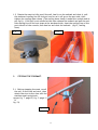
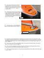
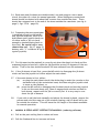
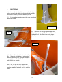
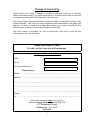
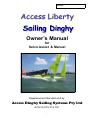
Sail No:
Access Liberty
Owner’s Manual
for
Servo Assist & Manual
Registered and Manufactured by:
Access Dinghy Sailing Systems Pty Ltd
ACN 56 079 318 031
1
Index
Page:
Introduction
..
..
..
..
..
3
Declaration of Conformity ..
..
..
..
4
Description of Craft: The Access Liberty:
Specification
..
..
..
..
5
General
..
..
..
..
..
6
..
..
..
..
7
Safety Recommendations ..
..
..
..
8
Special Features of the Liberty
..
..
..
9
How to Rig a Liberty
..
..
..
..
11
Liberty Servo Assist System
..
..
..
19
Servo Maintenance & Troubleshooting
..
..
24
Guarantee
..
..
..
26
..
..
..
27
Maintenance & Repairs
..
Change of Ownership Form
2
Introduction
This manual has been compiled to help you to operate your craft with safety and pleasure. It contains details
of the craft, the equipment supplied or fitted, its systems, and information on its operation and maintenance.
Please read it carefully, and familiarise yourself with the craft before using it.
If this is your first craft, or you are changing to a type of craft you are not familiar with, for your own comfort
and safety, please ensure that you obtain handling and operating experience before assuming command of the
craft. Your dealer or national sailing federation or yacht club will be pleased to advise you of local sailing
schools or competent instructors.
Please keep this manual in a safe place, and hand it over to the new
owner when you sell the craft.
Personal Floatation Devices (PFD’s)
There are many types and variety of buoyancy aids available, manufactured to different sets of standards. The
PFD is a personal item of safety equipment, designed specifically to assist in preserving a person’s life when in
the water. Some PFD’s provides buoyancy to help you float with your head above the water.
All sailors and volunteers should wear a PFD at all times whilst on, or near water.
PFD’s are subject to normal wear and tear. Each one should be checked regularly and if in doubt about its serviceability it should be replaced. If they become wet from salt water they should be hosed down with fresh
water and allowed to dry.
PFD’s and Children
A properly designed PFD of the correct size will keep a child’s mouth and nose clear of the water. A child
should be taught how to put on a device and should be allowed to try it out in the water. It is important that
the child feels comfortable and knows what the PFD is for and how it functions.
Safety Precautions
If sailed with care, this boat is unlikely to capsize in normal use, provided that the sail area is adjusted to suit
the prevailing conditions and the main sheet is not belayed. Whilst Access Dinghies have inherent design features ensuring maximum stability thereby reducing the chance of capsize, it should be remembered that these
are small sailing dinghies and under certain weather, water and sailing conditions sensible precautions should
be taken :
• Always reef the sails according to the weather conditions.
• Always have a manned safety boat in the sailing area.
• Always cancel sailing activities if inclement weather conditions dictate.
• Always lock centreboard in position with long centreboard locking pin provided.
Capsize and Man Overboard
Re-boarding after man overboard. In the event of man overboard, use keel handle as a handhold. Board over
the aft port or starboard sides.
Towing
The strong point for towing is the main mast. Pass the tow line through the guide ring at the bow and attach to
the mast with a bowline.
The safety of the sailors should come first under all circumstances.
3
Declaration of Conformity
Recreational Craft Directive 94/25/EC
LIBERTY
Model:
Hull Identification No:
Sail No:
Design Category C: “Inshore”
Capacity:
Craft designed for voyages in coastal waters, large
bays, estuaries, lakes and rivers where conditions
up to and including, wind force 6 and significant
wave heights up to, and including, 2 metres may
be experienced.
Maximum number of people: 1.
Maximum weight of people 120 kg.
Maximum weight of additional load 30 kg.
Built by:
Access Dinghy Sailing Systems Pty Ltd
2/7 Bungaleen Court
Dandenong, Victoria 3175
Australia
Ph: 61 3 9768 3101
Fax: 61 3 9768 3103
Email: [email protected]
REF
2
Using the moulds, parts,
and measurements
authenticated by
Access Dinghy Sailing Systems Pty Ltd
ESSENTIAL REQUIREMENTS
STANDARD USED
General Requirements
2.1
Hull Identification No (HIN)
ISO10087.95E (attached to craft)
2.2
Builders Plate
ISO14945:2004 (attached to craft)
2.4
Owner’s Manual
ISO10240:1996 (attached)
3
Integrity and Structural Requirements
3.1
Structure
3.2
Stability and freeboard
ISO12217-3:2002
3.3
Buoyancy and flotation
ISO12217-3:2002
3.4
Manufacturers recommended load
ISO14946:2001 (as shown on Builders Plate)
3.5
Towing
ISO15084:2003
5
5.4.1
ISO12215-1:2000 (as per Access Dinghy Sailing Systems Production Manual)
Steering Systems
General Steering System
ISO8847:2004
(manual joystick or servo assist controls)
Signed: .....................................................................
Chris Mitchell, Managing Director
Access Dinghy Sailing Systems Pty Ltd
4
Date: ..................................................
Description of Craft
The Access Liberty
Specification
Length
Beam
Draft
Boat Weight
3.6 mtrs.
1.35 mtrs.
1mtr.
72 kg
Maximum number of people: 1.
Maximum weight of people 120 kg.
Maximum weight of additional load 30 kg.
Centreboard Weight 72 kg
Sail Plan
Mainsail and free standing,` self tacking Jib.
Sail Area
Mainsail 4.5 sq. mtrs (unbattened and reefable to .5 sq. mtr).
Jib 1.75 sq. mtr (full roller reefing).
Mast
Main Mast (unstayed 5.6 mtr. Incorporating reefing drum in
foot).
Jib Mast (unstayed 3.5 mtr. Incorporating reefing drum in foot).
Hull
Positive buoyancy.
Heavily rockered for easy manoeuvrability.
Strong construction with solid bonded hull/deck joins.
Seating design keeps helm weight low, plus weighted centre
board makes the boat uncapsizable.
Seating
Fibreglass adjustable seat.
Controls
Steered by manual joystick.
Mainsail is reefed and unreefed by a single hauling line.
Jib is reefed and unreefed by a single hauling line.
Mainsail and Jib controlled by manual mainsheets.
Electric Controls
Servo-assist electric controls can be fitted to the Liberty.
5
General
The boat has an engraved plate fitted on the starboard side of forward cockpit,
showing the manufacturer, boat design category, maximum person capacity,
maximum additional load and the CE Mark. The parameters shown on this plate
should not be exceeded.
Steering is by a manual joystick located between the helm’s legs, moving it to the left
to go left and to the right to go right.
The sail area can be reduced or increased whilst under way using a reef furling system
operated by hauling on a single continuous line. (For further information on reefing see:
“How to Rig a 2.3 Access Dinghy: page 10 of the Manual).
Included with your Liberty is:
1. Liberty
2. Main Mast
3. Fore Mast
4. Boom
5. Centreboard
6. Rudder s x 2
7. Rubber Box x 2
8. Rudder Box Pin x 2
9. Installed reefing system
10. Mainsail
11.
12.
13.
14.
15.
16.
17.
18.
19.
20.
ITEMS WITH SERVO ASSIST
Installed:
main sheet winch
jib sheet winch
helm winch
control box
rubber bungs
Plus:
Batteries x 2,
Battery Y Connector,
Battery Charger (if 240V),
Controller
Controller holder
6
Foresail (Jib)
Bobbin
Mainsheet
Outhaul
Traveller
Painter
Jib Sheet with clew sheave
Jib strut downhaul
Jib Strut and Claw
Boom vang
Maintenance
It is recommended that the boat is covered when not in use to prevent UV and
other weather damage. A specially designed cover is available from Access Dinghy
Sailing Systems for this purpose.
If sails are to be left furled on the boat when not in use it is recommended that
these are covered using a protective sail sock to prevent UV and other weather
damage. These are available Access Dinghy Sailing Systems.
Do not let water remain in the boat when not in use. This can accelerate the
deterioration of running rigging, finishes and electrics where applicable.
Winter Storage: Remove electrics, remove sails and fully cover the boat.
Repairs
Contact Access Dinghy Sailing Systems, who will provide the best advice, along with
adapted parts or materials for the repairs you can carry out yourselves. Major
repairs should preferably be carried out by professionals.
7
Safety Recommendations
Access Dinghies are designed with a hull form and other features which combine to
give considerable stability. There is a simple set of rules which we must follow to
continue our excellent safety record and prevent any accidents. The stability of
the Access Dinghies are reliant upon the following factors.
Centreboards
It is most important that the keel be fully down when sailing. The hole one third
down the keel is there purely to facilitate sailing off a beach, and under no
circumstances should people with disabilities be allowed to sail around with the
keel held in this position. There is provision to lock the keel fully down so as even
in a “knock down” it remains in place.
The Liberty centreboard weighs 72kg and therefore must not be lifted manually.
Always use a hoist to place the centreboard into position.
Seating
Because the placement of sailor’s weight affects stability it is important that
people remain seated low in the boat. If a sailor needs support from strapping, use
only quick release velcro straps to hold the sailor in place. In no circumstances
should any other strap fixings be used.
Reefing
Being a displacement type hull extra sail area in strong winds does not mean more
speed, all it does is push the bow too far into the water and make it more difficult
to handle. In a breeze it is therefore recommended always to reef to suit the
stronger gusts.
Towing
If an Access dinghy needs to be towed on the water by another boat, it is safer and
easier to tie the dinghy close along side and remove the rudder blade so that it
cannot be “steered” in the wrong direction.
Transferring
A pontoon system which enables safe, keel down transfer of sailors to and from the
dinghy is available. Using this avoids off the beach keel handling and transferring
problems. It ensures that keels remain down throughout transferring.
Discriminatory Keel and Reefing Adjustments
For safety reasons people with disabilities need the keel down and because many
are unable to raise and lower the keel to improve sailing performance and also
unable to adjust the size of the sail by reefing, it is discriminatory to allow anyone
to make these adjustments during a race.
8
Liberty Special Features
1. The Liberty has 2 rudders which give
directional control at even extreme angles
of heel.
Fig 1
2. There is the option
of fitting a boom with a 3
part manual mainsheet,
rigged as per the 303W,
(fig 2)
Fig. 2
or a 2 part double ended
mainsheet (fig 3), one
end going to a servo assist sheet winch and the
other through a conventional swivel/deadeye/
camcleat for manual operation, (fig 4)
Fig. 3
Both these ends pass
through a double block
attached to the boom
about 400mm back from
the mast. (see fig 4)
3. A boom vang is fitted which prevents
the boom skying when running in fresh to
strong winds. (see fig 4)
Fig. 4
9
4. The mainsail outhaul primarily cleats at the boom, (fig 5) but passes thru a deckeye
just behind the main mast, down to the console and turns through the boom vang/outhaul
double becket block and back to the central of the 3 clamcleats on the port side of the console. (fig 6)
Fig. 5
Fig. 6
Fig. 7
5. The jib is self tacking with a diagonal
strut between the clew and a claw at the
mast which holds the jib flat and prevents
twisting as the sheet is eased. (fig 7, view)
6. The jib sheet is 2 part which gives the option of
one end going to a servo assist winch and the other
down to the camcleat on the starboard side of the
console for manual operation. (fig 8 shows the jib
sheet winch behind mast, jib sheet and camcleat).
Fig. 8
10
7. The Liberty has a solid seat designed to take cushions and padding to suit individual
needs. The adjustable backrests are available in short and long versions. Thoracic supports,
headrests and various types of seat belts are available. (fig 34 & 35)
If fig 34 is in B&W the yellow cross-over shoulder straps will be hard to see.
Fig. 34
Fig. 35
Rigging the Liberty
1.
STEPPING THE MAINMAST, FITTING THE BOOM.
1.1 With the sail rolled and tied up, bobbin in place tied to the tack of the sail
(fig 9), carefully step the mainmast making sure the foot is firmly in the step.
Fig. 9
11
1.2 Take the boom, free its outhaul and
sheet, pull the outhaul block and traveling ring as far forward as it will go, then
shackle the traveling ring onto the lowest hole of the clew board, and shackle
the outhaul to the central hole of the
clew board. (fig 10)
1.3 Unroll the mainsail (about 5 turns)
until the rowlock at the front end of the
boom can be pushed onto the bobbin.
1.4 Then pull the sail out tight with the
outhaul. Cleat the outhaul on the boom.
(see fig 5—page 10)
Fig. 10
1.5 Run the outhaul through the deck eye in the cowling just aft of the main mast,
down through the deadeye on the console just aft of the mast, then back to the black
clam cleat on the console port side. Pull on the outhaul, but cleat it at the white
clam cleat on the starboard side of the boom. (see fig 4—page 3)
1.6 Pass the boom vang through its block on the boom and back through its block on
the console just aft of the mast and cleat it at the furthest aft of the 3 black clamcleats on the port side of the console. Do not overtension the boom vang, it is there
to prevent the boom skying when running downwind in fresh to strong winds, not to
flatten the mainsail when going to windward. (see fig 4– page 9).
1.7 If the boat is to be sailed manually, and has a 3 part sheet fitted to the boom, use
the following procedure.
a) Unravel the sheet, clear any twists and shackle its block onto the traveler and rig
as per fig 2—page 9.
b) Pass the live end of the sheet through the deadeye and camcleat on the console
and tie a figure of eight knot in its end.
1.8 If the boat is to be sailed servo assist and has the sheet on its winch and a bare
boom, unravel the mainsheet which comes up through the console from the sheet
winch then: (as per figs. 3 & 4—page 9)
a) pass its end through the right side of the double block on the boom,
b) then through the plastic guide-ring half way along the boom,
c) then through the first of the blocks towards the end of the boom,
d) then down and through the block on the traveler,
e) then back up and through the block at the end of the boom,
f) then again through the plastic guide-ring, and then through the right side
of the double block,
g) and then down through the fairlead and cam cleat on the centre of the console.
h) tie a stopper knot in its end. If there was not enough rope for this operation set up the servo assist electrics and feed out sufficient rope. (see 3.1 on page
15)
12
1.9 Rotate the mast to fully unroll the sail, haul in on the outhaul and cleat it, pull
the starboard reefing line till its knot is as far as it will go on the port side, then
tighten the reefing drum clamp. (The reefing drum clamp is under the console and as
per fig 11). If full sail is not needed at this time release the outhaul and pull the port
side reefing line till its knot stops at the starboard side, cleat the reefing line on the
port side aft of the console, then haul on and cleat the outhaul. (fig 12, reefing
lines)
Fig. 11
2.
Fig. 12
STEPPING THE FOREMAST.
2.1 Before stepping the mast, unroll
the sail, fit the claw and strut, then
attach the strut to the claw with the
stainless steel spring hook.
(as per fig. 7– page 10; fig. 9—page 11
&
fig. 13)
Fig. 13
13
2.2 At the bow pull the port side jib
reefing line till its knot is at its stop
hard up on the port side of the console
in the cockpit. (see fig 12– page 13,
reefing lines)
2.3 Unhook the jib reefing line tension
shock cord hook (located on back bulkhead behind the seat) and set up the
reefing line in a loop to complete a full
turn around the foremast reefing drum.
(fig 14, view of loop)
Fig. 14
2.4 Step the mast, fit the reefing line
and re-tension the shockcord. (fig 15)
Fig. 15
2.5 Presuming the jib sheet block is shackled to the bottom hole of the clewboard, feed
the sheet through the block and down through the deckeye to the turning block, then thru
the deadeye and the cam cleat, then tie a stopper knot in its end. (see fig. 8—page 10 &
fig. 9—page 11).
2.6 At the bow is the jib strut downhaul, free it and attach its plastic hook to the lug on
the front of the claw. (fig 13—page 13).
2.6 Pull in on the downhaul (located on the left side of the console) and cleat it on the
most forward of the 2 black clamcleats. (fig 6 on page 10)
2.7 Check the manual operation of the jib sheet located at the cam cleat on the right side
of the console.
14
Fig. 16
2.8 To furl the jib, remove the strut, unhook
the downhaul, slide the claw to the base of
the mast then pull the port jib reefing line to
completely roll up the sail. (fig 16)
If fig. 16 is in B&W it may be hard to see the
orange sails rolled around the mast.
2.9
Its OK to roll 1 to 3 turns on the foremast to reef for strong winds, but for furling
do as per 2.8.
3.
IF SERVO ASSIST WINCHES ARE FITTED—SETTING UP MAIN & JIB SHEETS.
3.1 If sheet winches are fitted and the boat is to be sailed manually, it will be necessary to run all but about half a metre of sheet out of the winches to leave all the
sheet available for manual operation. Read carefully below (3.2 to 3.8) and PART
THREE for an understanding of the Servo Assist System.
3.2 Presuming the boat is servo
assist equipped it will be necessary to set up the main and jib
sheet winches to work in sync.
Commence by installing the batteries and connecting the joystick. (fig 17 showing battery
with Y connector going forward
around front of the centreboard
case to second battery).
See fig 26 on page 10 for a typical
joystick controller. Plug the joystick into the 9 way yellow connector on the lead below the
helm winch drum behind the seat
starboard side.
(fig 21 on page 19)
Fig. 17
3.3 On the joystick box is a push button switch (Main Only Switch or MO Switch)
which disconnects the jib sheet winch to allow the main sheet to be fine tuned independently. A red light is on when the MO Switch is activated. Press the button
again to operate both winches together. This function can be used to set up the
sheets so both main and jib are correctly set for windward work.
15
3.4 Both main and jib sheets are double ended, one end going to a servo assist
winch, the other to a cleat for manual operation. When sailing servo assist both
sheets should be cleated with about half a metre free outside the cleat. There
should be a stopper knot in the end of the sheet outside the camcleats. (see fig 4—
page 9, figs. 5 & 6 —page 10)
3.4 Presuming the servo assist gear
is installed correctly with battery
and joystick attached, wind in on
both sheets (pull joystick back) until either main or jib is in hard
enough to simulate being hard on
the wind. Be careful not to over
sheet either sail. (fig 17– page 15,
battery with “Y” connector & fig 26
typical joystick).
Fig. 26
3.5 For this exercise the mainsail is correctly set when the sheet is in hard and the
mainmast begins to bend aft, while the jib should be around 15 degrees off the centerline. That is the clew should be about 200 mm outboard from the mainmast.
3.6 If the jib sheets in hard first, press the MO switch to disengage the jib sheet
winch and use the joystick to further adjust the main sheet.
3.7 If the main sheets in first, either:
(a)
un-plug the main sheet winch (the white plug is under the console on the
starboard side of the centerboard case) and then using the joystick wind
in more on the jibsheet, or
(b) press the MO switch to disengage the jib sheet winch and use the joystick
to let out the main sheet only, then re-engage both winches and haul in
both sheets, repeat until the jib is correctly set. It is very easy to over
sheet the jib so beware.
3.8
If you wish to sail the boat manually and adjust the sheets by hand, reverse the
process and wind the rope out of the winches leaving a tail of about half a meter outside the winches. This will leave the full length of the sheets available
for manual operation.
4.
MANUAL & SERVO ASSIST—REEFING THE MAINSAIL: (reducing sail area)
4.1
Pull on the port reefing line to reduce sail area
4.2 Pull the Starboard line to increase sail area.
16
4.3 Never pull and “push” on both at once.
4.4 Use the white “clamcleats” on the left (port) side of the console to cleat the reefing line or the sail will unroll. (fig 20 on page18)
4.5 You can put one complete turn of sail around the mast without adjusting the outhaul.
4.6 To reef further the outhaul needs to be released to allow the sail to travel forward along the boom.
4.7 Conversely, when un-reefing, you need to pull on the outhaul.
4.8 Always re-cleat the outhaul after adjusting. Cleat the outhaul at the white clamcleat on the boom.
4.9 The idea is not to flatten the sail along
the boom as it should have enough slack to
form a gentle curve. (fig. 36 & fig. 37)
Fig. 36
Fig. 37
5.
REEFING AND FURLING THE JIB.
5.1 Un-cleat the jib sheet and downhaul before attempting to reef.
5.2 Use the port reefing line to reef, the starboard to unreef.
5.3 Remember to cleat the reefing line after reefing (use the “clamcleat on the console port side) or the sail will unroll.
5.4 Adjust the downhaul to suit.
5.5 To furl the jib, remove the strut, unhook the downhaul, slide the claw to the base
of the mast then pull the port jib reefing line to completely roll up the sail.
5.6 When de-rigging, leave the sheet block shackled to the clew, untie the figure of
17
6.
THE STEERING
6.1 Ensure the steering lines pass under the joystick correctly. A cable tie can be fitted through
the lower hole to prevent a derail. (fig 18)
6.2 Fit the rudders making sure the rope traveler is
above the tillers.
Fig. 18
Fig. 19
6.3 Remove the spring clips and pass the
clevis pins up through the holes at the end
of the tillers. Re-insert the spring clips.
(fig 19)
Fig. 20
6.4 Fit the alloy joystick extension. (fig
20). If there is a problem of sailors accidentally removing this joystick extension
a spring clip can be fitted. Contact Access Dinghy for details.
Also in fig. 20 are the two white camcleats on the aft port side of the console
used to cleat the mainsail and jib reefing
lines.
18
6.5 If the boat has Servo Assist winches fitted and is
to be steered manually, wind out (anticlockwise) the
helm winch drum to release the clutch. (fig 21)
6.6 If the boat is to be steered servo assist the clutch
needs to be engaged. Push the manual joystick hard
over to either port or starboard and do the same with
the helm winch by connecting battery and servo joystick and push it over to either port or starboard as
done with the manual joystick. This should align the
clutch. Then wind in (clockwise) the star knob to engage the clutch. (see fig 21)
6.7 To align the steering see Part 3, SERVO ASSIST
SYSTEM, 8.10 Adjusting the steering lines, page 25.
Fig. 21
7.
LAUNCHING
7.1 Pass the bow line (called a painter) through the guide ring at the bow and fasten it
around the mast using a bowline (a knot which is always easy to untie).
7.2 Use a hoist to lower the keel in place. Keels are best carried on shore in a Keel
Caddy or a common hand truck.
7.3 DO NOT ALLOW ANYONE TO SAIL WITHOUT THE CENTREBOARD FULLY DOWN OR
THEY MAY CAPSIZE.
7.4 USE THE LONG ALLOY PIN TO LOCK THE CENTREBOARD DOWN.
7.5 NEVER USE SEAT BELTS OR HARNESSES UNLESS THE CENTREBOARD IS LOCKED
DOWN.
Liberty Servo Assist System
1. OVERVIEW
1.1 Access Dinghies are extremely easy to sail servo assist and a severely disabled
sailor can be very competitive against anyone. Unfortunately, however efficient servo
assist equipment may be, sheet and helm winches will always be mechanical and
without feel, and slower than an able bodied person working sheets and joystick
manually. But without doubt, its better to be sailing without feel than not sailing at
all.
1.2
Servo Assist equipment is fitted only to our single seaters for three reasons.
(a)
Sailors who require servo assist generally have limited mobility which prohibits them moving body weight to windward to counteract heeling. The
boat will therefore heel more and single seaters with their wide side decks
stay dry, even at extreme angles of heel.
(b)
Sailors with limited mobility are more secure in the narrow single seater
cockpit.
(c)
As winches are less responsive than manual control, the boat is likely to
occasionally be heeled more in wind gusts, so the single seater is dryer.
19
1.3 The Liberty system comprises a control box with wiring harness (fig 22), helm
winch (fig 23—page 21), mainsheet winch (fig 24—page 22), jib sheet winch (fig 25—
page 22), controller (figs 26, 27, 28, 29, 30 & 31—pages 23 and 24) batteries (fig 32—
page 21) and battery charger (fig 33—page 21).
2.
CONTROL BOX. (fig 22)
2.1 The control box, part number
RC5, is hanging on a saddle inside
the starboard cockpit inspection
port. It has;
Fig. 22
(a)
3 leads running forward,
they are: (1) jib sheet
winch - long lead with red
plug. (2) main sheet
winch - mid length lead
with white plug. (3) battery - short lead with blue
plug. These leads run forward and out into the
cockpit via a 2 hole and a
1 hole rubber bungs, then forward through the back of the console to the
battery, the main sheet winch, and the jib sheet winch.
(b)
2 leads running aft, (1) the larger of the 2 passing through the aft bulkhead, via a 32mm single hole rubber bung, its yellow 9 pin plug connecting
to the joystick. (2) The smaller of the 2 aft leads plugs into the helm winch
lead (black plugs) which should always be hanging on a hook just aft of the
starboard side inspection port.
2.2 These plugs, except the yellow 9 way joystick plugs, should be sprayed with corrosion guard, particularly the blue battery plug which is the one most likely to get
wet.
(a)
Those left connected, ie, the male and female red jib sheet winch plugs
and the white mainsheet winch plugs, can be taped together and the mainsheet winch plugs pushed up under the console and held there with the
small piece of foam.
(b)
The black helm winch plugs can also be taped together and should be supported on the plastic hook inside the starboard inspection port.
(c)
The blue battery lead plug, when disconnected from the battery, should be
plugged into the dummy female plug attached to the console close to the
battery compartment. Never let these plugs lie in water. Spray them with
corrosion guard regularly.
20
3.
THE BATTERIES (fig. 17—page 15 & fig. 32)
3.1 2 batteries are provided which can be connected in parallel with the supplied
“Y” connector. (see fig 17– page 15)
3.2 One battery will power 3 to 5 hours sailing depending on load and usage.
3.3 Never allow the batteries to go dead flat. Charge batteries one at a time, leave
them overnight on the trickle charger supplied. (fig 33)
3.4 Spray the battery plugs with corrosion guard.
Fig. 32
‘
Fig. 33
4.
THE HELM WINCH (fig 23)
4.1 The helm winch has limit switches which
limit the travel of the tillers.
4.2 There is a clutch which disengages the steering line drum from the servo motor allowing for
manual steering. To engage the servo assist
steering it is easiest to engage the clutch by
pushing the manual joystick hard over to one
side and run the winch hard over the same way,
then screw in the drum to engage the clutch.
4.3 To align the steering see maintenance and
troubleshooting. (8.10 on page 25)
21
Fig. 23
5.
THE MAINSHEET WINCH (fig 24)
5.1 The main sheet winch employs a
friction drum which does not reel up
the sheet, but uses microscopic glass
beads to grip the rope on a single turn.
5.2 If the mainsheet winch is overloaded a 10 amp fuse, located on the
winch motor under the console, may
blow. Remove the winch to replace
the fuse. The fuse holder is taped to
the side of the motor.
Fig. 24
5.3 Do not tie a stopper knot in the end of the mainsheet. It is better to run the sheet
off the drum rather than have a knot cause a jam and the fuse to blow, or possibly cause
structural damage. See maintenance and trouble shooting to re-reeve and adjust the
mainsheet.
5.4 It is very effective to hang a canvas bag or plastic container below the winch to collect and contain coils of the mainsheet.
6.
THE JIB SHEET WINCH (fig 25)
Fig. 25
6.1 The jib sheet winch employs a friction drum
similar to the mainsheet winch.
6.2 If the jib sheet slips, re-tension the drum by adjusting the tension spring (nyloc nut and lock nut on
port side of winch drum shaft), or the rubber bands
are giving insufficient tension. Replace the rubber
bands if they are perished or broken. (The rubber
bands will soon be replaced with springs).
6.3 The jib sheet tail should be tied off at the saddle on the side of the console below the jib sheet
winch. This will prevent the tail end being caught
up in loops of the main and jib sheets.
6.4 Twists can develop in the jib sheet either side of
the winch. Periodically free the sheet and pull the
sheet through the fingers to unravel any twists.
6.5 The red plug lead running forward to the jib winch should be fed above the main
winch and above the main mast reefing drum (see fig 11 on page 13 for a view of what
the reefing drums looks like) and exit on the starboard side of the mast. It then goes
thru the hole in the front of the console and up to the jib sheet winch lead.
22
7.
CONTROLERS (figs 26 – 31)
7.1 There are 4 types of PRIMARY CONTROLLERS.
(a) 4-way joysticks - the basic system, the
simplest most reliable and easiest to use.
Can be operated by hand, chin or foot. (figs
26, 27, 28, 30 &31)
Fig 31 is a computer game type joystick
adapted with our 9 way connector as an example of what can be used.
Fig. 29
Fig. 26
(b) Sip and puff - (fig 29), where severe
quadriplegia prohibits the use of a joystick.
Each sailor requires a personal module to
guard against spread of infection. This is an
unnecessary added expense which can be
avoided for most sailors who are better off
using a joystick.
(c) Paddle switches - great for people with severe CP and the like who have difficulty
with fine finger movements and insufficient control of their breath for sip and puff.
(d) Push Button – 4 closely nested push buttons that can be operated under a thumb or
finger.
Fig. 27
Fig. 28
23
Fig. 30
Fig. 31
NB. Access Dinghy generally recommends that the boat should be controlled using the same
method as the sailor's wheelchair is driven, utilising the sailor's most moveable and agile
part, whether it be a hand, foot, chin etc. We do not generally recommend sip and puff
control systems except in those circumstances where other systems are unsuitable. Sip and
Puff can use unnecessarily complicated electronics which are therefore more prone to failure, and add an unnecessary complication and expense as each sailor needs their own personal module to guard against spread of infection. Only in North America are sip and puff
systems widely used.
7.2 Mainsheet Only Switches (MO Switch). When the MO Switch is activated the jib sheet
winch circuit is de-latched, so that when the Primary Control Switch is worked, only the
Mainsheet winch responds. Press the MO Switch again and both main and jib sheet winches
will work in sync. A red light is on when the MO Switch is activated.
7.3
There are 3 types of MO Switches.
(a) Finger controlled (latched) press button. (fig 26—page 23)
(b) Magnetic reed switch (latched) activated by a magnet attached to finger,
cheek or other moving body part. (fig 28—page 23)
(c )
Sip or puff (latched) switch (fig 29—page 23)
NB. Latching means the winch stays on when the switch is activated and must be pressed
again to stop it. Momentary switches are only "on" while being activated.
8.
MAINTAINANCE AND TROUBLESHOOTING.
8.1 We advise a club or owner to appoint a handy, practical volunteer to take charge of the
electrics, ideally someone with an electrical background.
8.2 This equipment has to be serviced regularly if it is to remain serviceable and free of
corrosion. Prior to leaving our factory all terminals, plugs and corrodible parts were sprayed
with “Corrosion Guard”, a spray can of which is supplied. We advise you to spray exposed
battery terminals regularly, and inspect all the electrical components regularly, noting and
treating any signs of corrosion.
8.3 Do not allow any leads and plug ends to remain immersed in water. When batteries are
removed plug the blue battery lead into the dummy connector attached to the side of the
console starboard side close above the battery compartment.
24
8.4 If components are swamped remove and dry them first if necessary, then spray
with “Corrosion Guard”
8.5 Remove the inspection ports to ventilate the buoyancy compartment when the
boat is packed away each day.
8.6 When the boat is stored for extended periods, remove (all) the electrics completely, service them and store in a dry place.
8.7 If the boat is usually sailed manually, remove the electrics till they are needed
again, closing all the holes with rubber bungs.
8.8 If the main sheet winch fails to work when activated first check the plug leads. If
all seems OK next listen at the control box to hear if the relays are clicking. If they are
the problem may be the blown fuse taped onto the side of the mainsheet motor which
is in the circuit to protect the components if the sheet winch motor is stalled and
overloaded. Remove the winch, remove the tape and replace the 10 amp x 12 volt
fuse.
8.9 If the MO switch fails to engage and disengage the jib winch it is most probably
dirty terminals in the 9 pin joystick connectors. Clean the pins. Do not spray the 9 pin
connectors with corrosion guard as the MO switch works with mille amps and corrosion
guard will inhibit a good contact.
8.10 Adjusting the steering lines. To align the steering, engage the clutch, rotate the
drum from lock to lock, then stop it at what you estimate to be the mid point. There
are steering line adjustments at the tillers and at the joystick. Adjust the lines so that
the joystick, tillers and the winch drum are all central. When you run the motor look
for the tillers to oscillate evenly port and starboard, and that the joystick oscillates
correspondingly. If not, adjust the lines till they are.
8.11 If the sheet is accidentally run through the winch, remove the winch, rotate the
threaded rod to release the rocker until the sheet can be fed back around the drum,
then re-tension the sheaves by rotating the rod. Reinstall the winch. If the rope slips
it could be that more sheave tension is needed, so adjust the threaded rod, or possibly
the glass beads are worn. Contact Access Dinghies in this event.
8.12
Changing between manual and servo a assist systems.
(a) If you wish to sail the boat manually and adjust the sheets by hand, wind the
sheets out of the winches leaving a tail of about half a meter outside the
winches. This will leave the full length of the sheets available for manual operation.
(b) To change back to servo assist winch operation reverse the above process and
wind the sheets in on the winches leaving about half a metre outside the camcleats. This will leave all the sheet available for servo use.
(c) To align the main and jib sheet winches to work in sinc refer to Part Two –
Rigging the Liberty, 3 Setting up main and jib sheets.
The Recommendations relating to corrosion should be taken very seriously and apply to
any environment, but the warmer and more humid your climate the more vigilant you
will have to be. IF YOU SAIL IN SALT WATER YOU SHOULD TAKE THESE RECOMMENDATIONS VERY SERIOUSLY.
25
Guarantee
If you need any help to resolve any problems with the boat, contact:
Access Dinghy Sailing Systems Pty Ltd
2/7 Bungaleen Court
Dandenong Victoria 3175
Australia
Ph: 61 3 9768 3101 Fax: 61 3 9768 3103
Email: [email protected]
Terms of Guarantee
1
This guarantee is valid for a period of 12 months from the date of purchase
from Access Dinghy Sailing Systems.
2
If any part or parts of the boat, including the rigging and fittings, is proved
to be defective by reason of faulty design, workmanship or materials, we
undertake to repair or replace the same free of charge, upon the following
conditions:
(a) This guarantee applies only to the original boat and fittings, and not to
any subsequent alterations, repairs or renewals.
(b) That, if at any time during the guarantee period, any parts are altered or
repaired by any person not authorised by us, then this guarantee will
immediately cease and become void concerning that part, or any other part
affected by the work.
(c) That our decision on all questions relating to any defect shall be
conclusive.
(d) That any part which has been replaced shall become our property.
(e) This guarantee specifically excludes damage resulting from external
impact.
None of the terms of this guarantee effect your statutory rights.
Name: .............................................................................................
Address: .............................................................................................
Owner of Access Dinghy
...............................................………….........
Sail No:
....................................................……………….
HIN No:
.............................................…………….........
is covered by the guarantee conditions displayed (above) in this Owner’s Manual,
delivered with this craft.
This guarantee begins ................................................................. (date)
Signature for Access Dinghy Sailing Systems
................................................................
26
Change of Ownership
Please ensure this Owner’s Manual is handed to the new owner as it contains
safety information that is of great importance to the new owner and is essential
to compliance with the EU Recreational Craft Directive.
The Access Dinghy Sailing Association is hoping to keep a continuous register of all
Access Dinghies. Your boat has been registered with them under your name and
address. In order to enable us to keep this register up to date it would be very
helpful if you could inform us of any change of ownership.
The form below is provided for you to photocopy and use to give us this
information if you sell the boat.
Please photocopy or copy:
Do not cut this form out of the manual.
Change of Ownership Form
Model:
Sail No:
Hull Identification No:
New Owner:
Name: .............................................................................
Address ..........................................................................
......................................................................................
......................................................................................
......................................................................................
Phone
No: ................................................................................
Please send completed copy of this form to:
Access Dinghy Sailing Systems Pty Ltd
2/7 Bungaleen Street
Dandenong Vic 3175
Australia
27