1
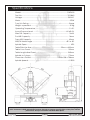
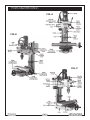
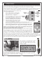
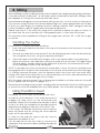
CLICK HERE TO VIEW /
BUY CLARKE SUPPLIES
FROM M&P
© AH0209
MILLING/DRILLING MACHINE
MODEL No. CMD300
Part No. 7610860
OPERATING AND
MAINTENANCE INSTRUCTIONS
Specifications
Model : .............................................................................................. CMD300
Part No : ............................................................................................. 7610860
Voltage : ............................................................................................. 230VAC
Motor : ..................................................................................................... 470W
Fuse Link Rating : ................................................................................... 5amp
Weight unpacked: .................................................................................. 51Kg
Operating Temperature : ..................................................................... 0°-40°
Sound Pressure Level: ..................................................................... 82 dB (A)
Max Drill Capacity : ............................................................................. 13mm
End Mill Capacity : ............................................................................... 16mm
Face Mill Capacity : ............................................................................ 30mm
Mill/Drill Head Angle ..................................................................... -45º to 45º
Spindle Taper : .......................................................................................... MT3
Table Effective Size : ............................................................ 92mm x 400mm
Table Cross Travel : ............................................................................. 100mm
Table Longitudinal Travel : ................................................................ 235mm
Spindle to Column : ........................................................................... 170mm
Dimensions DxWxH : ....................................................... 514 x 506 x 756mm
Spindle Speeds : ................................................................................... 0-2500
Please note that the details and specifications contained herein are correct at the time of going to
print. However CLARKE International reserve the right to change specifications at any time without
prior notice. Always consult the machines data plate.
2
Please read these instructions carefully before using this machine
Thank you for purchasing this CLARKE Milling/Drilling Machine, designed for drilling, deep
milling and face milling of small workpieces, with maximum dimensions of
300mmx200mmx200mm.
Before using the machine, you must read this manual thoroughly and carefully follow all
instructions given. This is for your own safety and that of others around you, and is also to
help you achieve a long and trouble free service from your new machine.
CLARKE GUARANTEE
This CLARKE product is guaranteed against faulty manufacture for a period of 12
months from the date of purchase. Please keep your receipt as proof of purchase.
This guarantee is invalid if the product is found to have been abused or tampered
with in any way, or not used for the purpose for which it was intended.
Faulty goods should be returned to their place of purchase, no product can be
returned to us without prior permission.
This guarantee does not affect your statutory rights.
Contents
Page
Specifications ................................................................................................ 2
Clarke Guarantee ........................................................................................ 3
Safety Precautions ..................................................................................... 4-5
Electrical Connections ................................................................................. 6
Installation ...................................................................................................... 7
Parts Identification ........................................................................................ 8
Operating Instructions
Drilling ........................................................................................... 10
Milling ........................................................................................... 12
Maintenance .............................................................................................. 14
Parts List & Diagrams ............................................................................. 15-19
Accessories ............................................................................................. 20-22
Declaration of Conformity ......................................................................... 23
When disposing of this product, do not dispose of with general waste. It must be disposed of according to the laws
governing Waste Electrical and Electronic equipment, at a recognised disposal facility.
3
General Safety Precautions
WARNING:
As with all machinery, there are certain hazards involved with their operation
and use. Exercising respect and caution will considerably lessen the risk of
personal injury. However, if normal safety precautions are overlooked or
ignored, personal injury to the operator or damage to property, may result.
1. ALWAYS learn the machines’ applications, limitations and the specific potential
hazards peculiar to it. Read and become familiar with the entire
operating manual.
2. ALWAYS use a face or dust mask if operation is particularly dusty.
3. ALWAYS check for damage. Before using the machine, any
damaged part, should be checked to ensure that it will operate
properly, and perform its intended function. Check for alignment of
moving parts, breakage of parts, mountings, and any other condition
that may affect the machines’ operation. Any damage should be properly repaired
or the part replaced. If in doubt, DO NOT use the machine. Consult your local dealer.
4. ALWAYS disconnect the tool/machine from the power supply before servicing and
when changing accessories.
5. ALWAYS wear safety goggles, manufactured to the latest European Safety Standards.
Everyday eyeglasses do not have impact resistant lenses, they are not safety glasses.
6. ALWAYS keep work area clean. Cluttered areas and benches
invite accidents.
7. ALWAYS ensure that adequate lighting is available. A
minimum intensity of 300 lux should be provided. Ensure
that lighting is placed so that you will not be working in your
own shadow.
8. ALWAYS keep children away. All visitors should be kept a
safe distance from the work area, especially whilst operating
the machine.
9. ALWAYS maintain machine in top condition. Keep tools/machines
clean for the best and safest performance. Follow maintenance
instructions.
10. ALWAYS handle with extreme care do not carry the tool/machine
by its’ electric cable, or yank the cable to disconnect it from the
power supply .
11. ALWAYS ensure the switch is off before plugging in to mains. Avoid accidental starting.
12. ALWAYS concentrate on the job in hand, no matter how trivial it may
seem. Be aware that accidents are caused by carelessness due to
familiarity.
13. ALWAYS keep your proper footing and balance at all
times, don’t overreach. For best footing, wear rubber
soled footwear. Keep floor clear of oil, scrap wood, etc.
-5-
4
14. ALWAYS wear proper apparel. Loose clothing or jewellery
may get caught in moving parts. Wear protective hair
covering to contain long hair.
15. ALWAYS use recommended accessories, the use of improper
accessories could be hazardous.
16. ALWAYS remove plug from electrical outlet when adjusting,
changing parts, or working on the machine.
17. NEVER operate machine while under the influence of drugs, alcohol or any medication.
18. NEVER leave machine running unattended. Turn power off.
Do not leave the machine until it comes to a complete stop.
19. NEVER force the machine, it will do a better and safer job at
the rate for which it was designed.
20. NEVER use power tools in damp or wet locations or expose
them to rain. Keep your work area well illuminated.
21. DO NOT use in explosive atmosphere (around paint,
flammable liquids etc.). Avoid dangerous environment.
Additional Precautions For Mill/Drills
1.
ALWAYS use the appropriate cutter for the material being cut.
2.
ALWAYS ensure the cutter is fully secured before use.
3.
ALWAYS switch the machine OFF immediately the task is completed.
4.
ALWAYS ensure safety guards etc., are in place and working correctly, if not DO NOT
use the machine until rectified.
5.
DO NOT use the machine if the electric cable, plug or motor is in poor condition.
6.
DO NOT allow the ventilation slots in the machine to become blocked.
7.
DO NOT touch the cutter immediately after use, allow time for it to cool.
8.
NEVER leave chuck keys in situ, Always remove and store safely when finished
tightening or loosening the chuck.
9.
NEVER change from high to low speed and vice versa whilst the machine is still
running, always ensure the machine has come to a complete stop before doing so.
10. NEVER change from forward to reverse and vice versa whilst the machine is still
running, always ensure the machine has come to a full stop before doing so.
11. NEVER leave machine running unattended, ALWAYS ensure it is switched off and has
come to a complete stop before leaving it.
12. AVOID accidental starting, by switching off and isolating from the main electrical
supply by removing the plug from the socket.
Additionally, please keep these instructions in a safe place for future reference.
5
Electrical Connections
This product is provided with a standard 13 amp, 230 volt (50Hz), BS 1363 plug, for
connection to a standard, domestic electrical supply. Should the plug need changing at
any time, ensure that a plug of identical specification is used.
WARNING ! THIS APPLIANCE MUST BE EARTHED
This machine must be wired up in accordance with the following colour code:
BLUE
- NEUTRAL
BROWN
- LIVE
GREEN/YELLOW - EARTH
•
•
•
Connect the BLUE coloured cord to the plug terminal marked “N”
Connect the BROWN coloured cord to the plug terminal marked “L”
Connect the GREEN/YELLOW coloured cord to the plug terminal marked “E”
If this appliance is fitted with a plug which is moulded on to
the electric cable (i.e. non-rewireable) please note:
1.
The plug must be thrown away if it is cut from the
electric cable. There is a danger of electric shock if it is
subsequently inserted into a socket outlet.
2.
Never use the plug without the fuse cover fitted.
3.
Should you wish to replace a detachable fuse carrier, ensure that the correct
replacement is used (as indicated by marking or colour code).
4.
Replacement fuse covers can be obtained from your local dealer or most electrical
stockists.
Fuse Rating
The fuse in the plug must be replaced with one of the same rating (5 amps) and this
replacement must be approved to BS1362.
If in doubt, consult a qualified electrician. Do not attempt any electrical repairs yourself.
Cable Extension
Always use an approved cable extension suitable for the power rating of this tool (see
specifications), the conductor size should also be at least the same size as that on the
machine, or larger. When using a cable reel, always unwind the cable completely.
IMPORTANT:
If a cable extension is needed, it is essential to comply with the following data.
Voltage
230v
230v
Extension length
Up to 20M
From 20 to 50M
6
Cable section
2.5mm 2
4mm2
Installation
IMPORTANT:
Careful consideration is required when choosing the location for the
machine, with regard to table movement, Mill/Drill Head movement and location of
power supply. Additionally, the workbench should be firm, flat and level. Avoid installing
in damp or very dusty locations and ensure that adequate light is provided.
Your new machine is delivered fully assembled (except for handles which are contained
in a bag of loose parts), and bolted to a board with four bolts. Various tools and
accessories are also contained in the bag of loose parts - see Fig.1.
To remove the machine from the case, carefully lay the carton on its side and break the
seal at the bottom. Fold the three flaps back and gently turn the carton so that it is upright.
Tilt the carton in order to fold back the remaining flap then lift the carton from the
machine and packing material.
Fig.1
List of Loose Items
1.
Double open ended spanner 8 - 10mm AF
2.
Double open ended spanner 14 - 17mm AF
3.
Double open ended spanner 17 - 19mm AF
4.
2 x ‘T’ nuts
5.
Set Hex. Wrenches. 3,4,5 & 6mm
6.
Drill Chuck w/taper shank
7.
Chuck Key
8.
3 x Levers/Handles
9.
Tommy Bar
10.
Draw bolt for taper shank
11.
Peg Spanner
12.
Open ended spanner - 36mm AF
13.
2 x handles for Wheel adjusters
14.
Oil Bottle
15.
Chuck Guard
Not shown: 1x Spare Fuse. 3Amp.
7
Parts Identification
FIG-A
FIG-B
FIG-C
8
1.
Remove all polystyrene packaging material, then, with assistance lift the machine on
to a workbench. DO NOT attempt to do this single handedly.
2.
Unbolt the machine from the board - 4 nuts with countersunk screws and washers,
and, with assistance, carefully slide or lift into position on your workbench.
3.
Before drilling the bench in order to secure the machine, ensure :
4.
•
the head can be raised to its full height - 755mm from the table surface,
•
the head can be pivoted in either direction through 45º without fouling,
•
adequate clearance is available for the longitudinal travel of the cross slide.
Once satisfied, drill four holes corresponding with those in the machine base, and bolt
the machine securely to the workbench using M10 nuts bolts and washers, (not
supplied).
4a. Alternatively, the Mill/Drill may be mounted centrally on a board of at least 20mm (3/4”)
thickness, and of minimum size, 455x455mm (18”x18”).
This allows the Mill/Drill to be moved to somewhere more convenient when not in use,
in a small workshop. The board may then be clamped securely (with ‘G’ clamps) to
a workbench when required for use.
5.
Screw the three handles into the head raise/lower hub.
6.
Screw a handle to each of the table cross feed and longitudinal feed handles, and
secure with the locknuts provided.
7.
If using the Drill chuck, attach the clear plastic chuck guard to its mount, using the
single screw provided.
8.
Any preservative must be cleaned off thoroughly using a solvent, then dried and a
thin film of machine oil applied to all untreated surfaces. Take great care when using
the solvent, do not to allow it to get into the motor or electrical components switches etc.
9.
Lightly lubricate all moving parts, handwheel threads etc., with machine oil.
10. Check to ensure the post is secure by attempting to tighten the post securing nut at
the rear of the machine using the 36mm spanner provided.
Your Mill /Drill is now ready for use.
9
OPERATION
Ensure the work area is clean and tidy and all tools and accessories etc., are removed
and stored safely, before plugging the machine into the electric supply.
Switch the power ON. At this point, the green indicator lamp on the switch panel on the front
of the machine, will illuminate, indicating that power is being supplied to the machine.
Fig.2
When first using the machine, please use
the following procedure.
1.
Select LOW range, by moving the
Lever, adjacent to the Emergency
Stop, fully to the ‘L’ position.
2.
Push the emergency OFF switch cover
button (fig.2) upwards in direction of
arrow. This will allow the cover to spring
outwards, releasing the OFF button.
3.
Start the machine by turning the rotary
ON/OFF, variable speed switch, slowly
clockwise to mid position, and allow to run for a minute or two
before winding up to full speed, then allow to run for a further two minutes.
4.
Fig.3
Switch OFF by turning the rotary switch fully anticlockwise, then move
the Hi-Lo range lever to the ‘H’ - high position, and repeat the process.
NOTE: In case of emergency, hit the switch cover quickly. The cover will
latch down and the motor will be switched OFF.
The machine will not start when the emergency switch cover is closed.
If the emergency switch is used to switch OFF, when the rotary ON/OFF
switch in the ON position, the machine will not start again when the
emergency switch is released. The amber warning lamp will also illuminate.
The rotary switch must first be turned OFF then turned ON again to start the machine.
Once the machine has been ‘run up’ check to ensure that the machine is secure on the
bench or board, and check again to ensure the post is secure by attempting to tighten the
post securing nut at the rear of the machine using the 36mm spanner provided.
Fig.4
A. Drilling
Fig.5
The machine is provided with a drill
chuck and morse taper shank - Fig.4.
Insert the taper shank up into the
spindle, sharply.
CAUTION. Take extreme care not to
damage the taper in any way. Any
burr or irregularity will render it
unserviceable until it is properly
repaired using a grind stone.
Professional advice should be sought.
Pull off the spindle draw bolt cover from the head (see Parts ID, Fig-C on page
8s) and insert the draw bolt . Screw it into the end of the taper shank and
tighten using the spanner provided - see Fig.5.
10
In order to hold the spindle, insert the Tommy Bar into the hole in the side of the head so
that it locates in the hole in the spindle, see Fig. 5. Hold the spindle still whilst nipping up the
draw bolt. .
Fig.6
Place the drill chuck on to the end of the taper shank with
a sharp upward movement.
The drill is lowered using the levers on the right side of the
machine, however, in order to do so, it is first of all
necessary to disconnect the Dog Clutch, shown in Fig. 6.
Simply pull back on the hub to disconnect.
Now by turning the handles, the drill head may be lowered.
In order to ensure the drill chuck is firmly secured on the
spindle, place a piece of wood on the table then lower
the drill head so that the nose of the drill chuck comes
into contact with it. Pull down sharply one time.
When drilling using a mill/drill machine, it must be
remembered that without care, the drill bit could easily
come into contact with the surface of the table.
Drill head travel must always be restricted therefore
before proceeding to drill, otherwise damage to the
table and/or drill bit could occur.
Fig.7
A limiting device is provided, mounted on the post
slide, shown in Fig. 7.
When through drilling, wind the drill head, with drill bit
installed, down to the maximum depth required, and
hold in place whilst sliding the limit device up to meet
it. Lock the limit device in place using its’ locking lever.
The limit device is also used if you wish to drill to a
predetermined depth.
Bring the drill bit down to touch the workpiece surface
and note the reading on the scale on the post.
Move the workpiece away from the drill bit, using the
longitudinal or cross slide handles, then lower the head once again to the depth
previously noted, plus the depth of hole required. At this point, bring the limit device up to
the head and lock firmly in place . Your drill depth is now set.
The workpiece must ALWAYS be firmly secured. This will normally be with the use of a vice
which is securely clamped to the table. Alternatively, clamps may be used. A suitable
vice, and a ‘T’ nut and clamp set designed specifically for this machine, are available
from your Clarke dealer. Please refer to Accessories on page 22.
The table, carrying the workpiece, is manoeuvred using the longitudinal and cross slide
adjusting handles. Once the workpiece is positioned, any further movement is avoided by
locking both longitudinal and cross slides in place using the locking levers provided - see
parts identification Fig-B, on page 8.
Drill speeds are effected by using either the High or Low ranges together with the variable
speed rotary switch. See notes on cutting speeds on page 13.
WARNING
Never attempt to change ranges until the machine has come to a complete stop
11
17
B. Milling
Vertical Milling is similar to drilling, except that instead of the workpiece being held stationary,
it may be moved in 3 directions - a. vertically, and b. horizontally in both axis. Milling cutters
are capable of cutting with their ends and their faces.
Several broad categories of end and face milling tools exist, such as centre cutting versus
non-centre cutting (whether the mill can take plunge cuts), and categorisation by number
of flutes, by helix angle, by material, and by coating material. Each category may be
further divided by specific application and special geometry.
Please note that It is not within the scope of this manual to advise on types of cutter, it is
assumed that the user is familiar with milling applications, cutters and techniques.
This machine is also capable of milling at any angle from vertical - 90º, to 45º left or right
of vertical.
Installing the Cutter
If the chuck is installed, proceed as follows:
1.
Insert the tommy bar into the hole in the side of the head so that it locates in the hole
in the spindle.
2.
Remove the draw bolt cover and with the spindle being held, undo the draw bolt by
two complete turns only, using the spanner provided.
3.
Strike the head of the draw bolt sharply with a soft faced mallet, or by placing a
piece of wood on the head and striking the wood with a hammer. The taper shank
will disengage, thereby allowing the draw bolt to be fully unscrewed and the drill
chuck and taper shank to be withdrawn.
NOTE: It is possible that when the head of the draw bolt is struck, the chuck could become
disengaged with the taper shank and drop on to the bed, with possible resultant damage.
It is strongly advised therefore, that the operator holds the chuck with one hand whilst
striking the head of the draw bolt, or a substantial piece of cloth is placed beneath the
chuck, in order to avoid damage when it drops.
With the taper shank removed, the cutter may be installed in a similar manner to the drill
chuck, please see the notes on pages 10/11.
Please note that a range of accessories, including collet sets and collet chuck sets which are used
to secure the cutter, are available from your Clarke dealer - see Accessories on page s 20/21.
Using the Micro Feed
For Milling, the micro feed should always be used.
In order to use this device, it is first of all necessary to
engage the dog clutch on the raise/lower hub
assembly. Simply turn the raise/lower handles until the
cutter is as near the workpiece as possible and the
dogs become aligned, then push the hub IN fully.
In this mode, the handles cannot be used to raise or
lower the head, only by turning the micro adjuster
knob, will this be effected.
A scale on the adjuster sleeve may be used to
determine the depth of cut.
Turn the adjuster so that the cutter just touches the
workpiece, then zero the scale by holding the adjuster
12
Fig.8
knob whilst grasping the knurled rim of the scale and turning until the zero on the scale lines
up with the pointer. Back off slightly and start the machine.
Turn the adjuster once again until the zero mark lines up with the pointer and double check
that the cutter is just touching the work - if not, make the necessary adjustment. Any further
movement of the adjuster will commence cutting.
General Notes on Milling
Set up the workpiece in a similar manner to that for drilling.
•
Slowly bring the cutter into contact with the work piece and start machining.
•
DO NOT attempt to make too bigger cuts than the cutter and machine are capable
of, it is much better and safer to make several small passes.
•
Always use an appropriate cutting/cooling fluid whilst machining, which can be
applied with a small brush etc., NOT FINGERS.
•
DO NOT allow swarf to build up in the cutting area. Stop the machine and remove
using a suitable implement, (brush etc.).
•
When finished turn the machine OFF, return the cutter to its highest position and allow
it to come to a complete stop before attempting to remove the work piece or tool.
•
Always finish by cleaning and drying the machine, and storing all tools and accessories
etc., safely.
Cutting Speeds
In order to drill, and particularly mill satisfactorily, it is most important that the correct
cutting speed is used,
Cutting speed is the speed at which the cutting edge of the tool passes over the work.
This is usually expressed in feet per minute or metres per minute.
For a given material there will be an optimum cutting speed for a certain set of machining
conditions, and from this speed the spindle speed (RPM) can be calculated. Factors
affecting the calculation of cutting speed are:
•
The material being machined (steel, brass, aluminium etc. - see table below)
•
The material the cutter is made from i.e. Carbon steel High speed steel (HSS), carbide,
or ceramics.
Material type
meters per min
feet per min
Steel (tool)
15 - 18
50 - 60
Mild steel
30 - 38
100 - 125
Cast iron (medium)
18 - 24
60 - 80
Bronzes
24 - 45
80 - 150
Brass (soft)
45 - 60
150 - 200
Aluminum
75 - 105
250 - 350
A good rule of thumb is, the smaller the hole or depth of cut, and the softer the material to
be machined etc, the faster the speed.
Please note that It is not within the scope of this manual to provide a tutorial on cutting
speeds or the methods used to determine spindle speeds (RPM), for your particular
application. It is assumed that the operator is familiar with these practices.
13
Maintenance
The amount of maintenance depends on the amount of use the machine gets. However,
it is important to carry out routine maintenance to prevent premature wear and shortening
the life of the machine.
1. Inspect and clean all non painted surfaces. Lubricate using a light machine oil. Do
Not over lubricate. Oil can be applied to the work table and column etc., using a soft
oil soaked cloth.
2. Inspect and clean all moving parts. Lubricate using machine oil. Check for smooth
operation.
3. Inspect the machine for signs of wear or damage. Any faults should be rectified
before continuing.
4. Check all nuts and bolts etc. are tight.
Slide Adjustments
With use, play may develop in the cross, longitudinal and the post slides. It is possible to
adjust these components in order to eradicate any unnecessary movement.
Before making any adjustments, clean all friction surfaces. It is necessary to move the table
and cross slide to both extremes to carry out the cleaning process correctly.
When finished cleaning, re-lubricate using a light machine oil.
Return both the table and cross slide to their central positions.
Fig.9
Adjustment is effected by means of Jib Strips. These
are precision machined steel strips, positioned
between the mating surfaces as shown in Fig.9. The
strips are adjustable so as to apply pressure on these
surfaces, sufficient for the parts to slide easily about
each other without unnecessary slackness. The
longitudinal slide for example carries four adjusters,
shown in Fig.10.
To adjust, first ensure that the slides are lubricated
with a thin film of machine oil as described
previously.
Fig.10
Slacken off all adjuster locknuts, using the
hex. wrench provided, and back off each
adjuster by half a turn.
Screw IN each adjuster in turn until a slight
resistance is felt.
Wind the slide through its full travel to check
that there are no high spots, and travel is
smooth throughout.
If the slide moves smoothly and all slack has
been eliminated, hold the adjuster still and
tighten all lock nuts.
Finally, wind the slide through its full length once again to double check. If there is any slack
or tightness, readjust as described above.
14
Parts Diagram
15
Parts Diagram
16
Parts Diagram
PARTS & SERVICE TEL: 020 8988 7400
or e-mail as follows:
PARTS: [email protected]
SERVICE: [email protected]
17
Parts List
Item
Description
Qty
Part No
Item Description
Qty
Part No
SGCMD300040
1
Base
1
SGCMD300001
40
Spring washer 10
3
2
X-axis feed screw
1
SGCMD300002
40-1
Washer 10
3
SGCMD3000401
2-1
Key 4xl6
2
SGCMD300003
41
Cap screw Ml0 x 30
3
SGCMD300041
4
Dial
2
SGCMD300004
42
Pointer
2
SGCMD300042
5
Hand wheel
2
SGCMD300005
43
Set screw M6 x 22
7
SGCMD300043
6
Nut M8
2
SGCMD300006
44
Scale
1
SGCMD300044
7
Knob
2
SGCMD300007
45
Jib Strip
1
SGCMD300045
8
Screw M8 x 55
2
SGCMD300008
46
Gear rack
1
SGCMD300046
9
Cap Screw M6x8
8
SGCMD300009
47
Cap screw M6 x 12
4
SGCMD300047
10
Plate (1)
1
SGCMD300010
48
Label
1
SGCMD300048
11
Dust guard cover
1
SGCMD300011
49
Spindle box
1
SGCMD300049
12
Plate (2)
2
SGCMD300012
50
Pinion
1
SGCMD300050
13
Ball bearing 8200
2
SGCMD300013
51
Key 4x25
1
SGCMD300051
14
Washer
2
SGCMD300014
52
Bevel gear
1
SGCMD300052
15
Nut M8
4
SGCMD300015
53
Retaining ring 12
1
SGCMD300053
16
Y-axis scale
1
SGCMD300016
54
Ball
1
SGCMD300054
17
Cap screw M6 x 16
4
SGCMD300017
55
Spring 0.8 x 0.8 x 10
1
SGCMD300055
18
Y-axis bearing seat
1
SGCMD300018
56
Screw 6 x 8
1
SGCMD300056
19
Work table
1
SGCMD300019
57
Handle Hub
1
SGCMD300057
20
Y-axis feed screw
1
SGCMD300020
58
Operating lever
3
SGCMD300058
21
End cover
I
SGCMD300021
59
Handle
3
SGCMD300059
22
Screw M6 x 10
2
SGCMD300022
60
Cap screw M8 x 25
4
SGCMD300060
23
Y-axis screw nut
1
SGCMD300023
61
Pointer
1
SGCMD300061
24
Holding plate (3)
1
SGCMD300024
62
Cap screw M6 x 25
1
SGCMD300062
25
Dust guard cover
1
SGCMD300025
63
Spindle box seat
1
SGCMD300063
26
Screw seat
1
SGCMD300026
64
Jib Strip
1
SGCMD300064
27
Cap screw M6 x 16
2
SGCMD300027
65
Limit block
1
SGCMD300065
28
Set screw M6 x 22
6
SGCMD300028
66
Jib Strip
1
SGCMD300066
29
Nut M6
13
SGCMD300029
67
Scale
1
SGCMD300067
30
Handle
3
SGCMD300030
68
Vertical Post
1
SGCMD300068
31
Screw M6 x 10
2
SGCMD300031
69
Electric box
I
SGCMD300069
32
Pointer
1
SGCMD300032
70
Lock nut M24
1
SGCMD300070
33
Screw M6 x 8
1
SGCMD300033
71
Large washer
1
SGCMD300071
34
X-axis Jib Strip
1
SGCMD300034
72
Connecting strut
1
SGCMD300072
35
Saddle
1
SGCMD300035
78
Key 5x5x40
1
SGCMD300078
36
Y-axis Jib Strip
1
GCMS3000036
79
Spindle
1
SGCMD300079
37
X-axis screw nut
3
SGCMD300037
80
Transmmision gear
1
SGCMD300080
38
Cap screw M6 x 25
2
SGCMD300038
81
Support Block
1
SGCMD300081
39
Vertical Post seat
1
SGCMD300039
82
Screw
2
SGCMD300082
39-1
Shaft
1
SGCMD3000391
83
Pin 4x78
1
SGCMD300083
39-2
Key 8 x 12
1
SGCMD3000392
84
Worm
1
SGCMD300084
18
Parts List
Item
Qty
Part No
85
Sleeve
Description
1
SGCMD300085
Item Description
Qty
Part No
126
Cover
1
86
Pin 3xl2
I
SGCMD300086
127
Motor
1
SGCMD300127
87
Pin 3xl2
2
SGCMD300087
128
Motor gear
1
SGCMD300128
SGCMD300126
88
Adjustable union
1
SGCMD300088
129
Ring 9.0
1
SGCMD300129
89
Bracket
1
SGCMD300089
130
Motor seat
1
SGCMD300130
90
Screw M5x25
1
SGCMD300090
131
Screw M6 x 12
4
SGCMD300131
91
Dial
1
SGCMD300091
132
Round screw M5 x 8
4
SGCMD300132
92
Spring steel 1.0
3
SGCMD300092
133
Yellow lamp
1
SGCMD300133
93
Small hand wheel
1
SGCMD300093
134
Speed control knob
1
SGCMD300134
94
Screw M8 x 16
1
SGCMD300094
135
Green lamp
1
SGCMD300135
95
Small shaft
1
SGCMD300095
134
Fuse box
1
SGCMD300136
96
Cover
1
SGCMD300096
137
Emerg. stop switch
1
SGCMD300137
97
Screw M4 x 6
2
SGCMD300097
138
Gear
I
SGCMD300138
98
Dust cover support
I
SGCMD300098
139
Ball bearing 80101
2
SGCMD300139
SGCMD300140
99
Screw MS x 16
2
SGCMD300099
140
Transmission gear
1
100
Dust guard
1
SGCMD300100
141
Bar
1
SGCMD300141
101
Clamp bolt M6 x 12
1
SGCMD300101
142
Link board
1
SGCMD300142
102
Upper end washer
1
SGCMD300102
143
Set screw MS x 8
1
SGCMD300143
103
Upper end screw M6
1
SGCMD300103
144
Self-tapping Screw
2
SGCMD300144
104
Setscrew M6 x 6
1
SGCMD300104
145
Hi/Low label
1
SGCMD300145
105
Spring 0.8 x 4.8 x 10
1
SGCMD300105
146
Motor cover
1
SGCMD300146
106
Ball
1
SGCMD300106
147
Motor conn. flange
1
SGCMD300147
107
Handle seat
1
SGCMD300107
148
Screw M6 x 10
4
SGCMD300148
108
Double head bolt M8 1
SGCMD300108
149
Warning lable
1
SGCMD300149
109
Knob
1
SGCMD300109
150
PC board
1
SGCMD300150
110
Warning label
1
SGCMD300110
151
Locking sleeve
1
SGCMD300151
111
Controller
1
SGCMD300111
152
Rotor shaft
1
SGCMD300152
112
Label
1
SGCMD300112
153
Key4x6
1
SGCMD300153
113
Shaft
1
SGCMD300113
154
Spring support
1
SGCMD300154
SGCMD300155
114
Double round hd key
1
SGCMD300114
155
Torsion spring
1
115
Internal Ring
1
SGCMD300115
156
Cover
1
SGCMD300156
116
Spacing Ring
2
SGCMD300116
157
Nut
1
SGCMD300157
117
Small shaft
1
SGCMD300117
158
Extension tube
1
SGCMD300158
118
Spacing Ring
1
SGCMD300118
159
Supporting arm
1
SGCMD300159
119
Spindle nut
1
SGCMD300119
160
Screw
1
SGCMD300160
120
Double round hd key
1
SGCMD300120
161
Washer
2
SGCMD300161
121
Cap screw M5 x 8
6
SGCMD300121
162
Internal ring 12
1
SGCMD300162
122
Bearing cover
2
SGCMD300122
163
Cover
1
SGCMD300163
123
Ball bearing 80206
2
SGCMD300123
164
Top Cover
1
SGCMD300164
124
Name label
1
SGCMD300124
165
Screw M 3 x 6
4
SGCMD300165
125
Fine feed label
1
SGCMD300125
19
Accessories
1. Mill Chuck Set
Part Number: 7610866
A set comprising 7 collets, a chuck and
‘C’spanner.
Collet sizes:
•
4 mm
•
6 mm
•
8 mm
•
10 mm
•
12 mm
•
14 mm
•
16 mm
A
1.
Insert the shank of the chuck into the Mill Head Spindle and screw on to the end of
the draw bolt. Tighten the draw bolt, holding the spindle steady by hand or by inserting
the tommy bar provided in the hole in the side of the head and into the spindle.
2.
Unscrew and remove the end collar ‘A’, insert the appropriate collet and reattach
the end collar.
3.
Insert the respective end mill into the collet and tighten the end collar using the ‘C’
spanner.
To remove the chuck, undo the draw bolt a turn or two, then tap its’ head using a mallet to break
the seal.
2. HSS End Mill (2-Fluted)
Part Number: 7610874
A set of 7 End Mills, of the following sizes,
for use with the Mill Chuck or Collet Set
•
4 mm
•
6 mm
•
8 mm
•
10 mm
•
12 mm
•
14 mm
•
16 mm
20
3. Collet Set (MT3)
Part Number: 7610864
A set of 7 Collets for use with the HSS End
Mills:
Insert the appropriate Collet into the
spindle.
Insert the draw bolt, provided, into the
spindle, from the top and screw on to the
Collet a few turns.
Insert the appropriate Mill into the jaws of
the Collet, and tighten the draw bolt.
Hold the spindle by means of the tommy bar,
inserted in the hole in the side of the head,
and into the hole in the spindle.
To remove the Collet, unscrew the draw bolt
a few turns and tap its head with a mallet
to break the seal between the Collet and
spindle.
4. Quick Release Vice
Part Number: 7610868
‘T’ nuts are provided with the base machine
Maximum opening:
88mm
Effective Jaw size:
100x33mm
21
5. Indexable Carbide End Mill
Part Number: 7910870
Simply insert the shank of the mill into the
spindle and screw on to the Draw Bolt.
Tighten using the Tommy Bar in the hole in
the side of the head, into the spindle, and
spanner on the Draw Bolt head.
Disassemble in the same manner as for the
drill chuck.
6. Clamp Set
Part Number: 7610872
An example of how the clamp set may be used:
Select the appropriate studs and
slotted clamp. Screw the ‘T’ nut on
to the stud and assemble as
shown, using the appropriate
stepped blocks adjust the blocks
so that the clamp
is horizontal.
22
23