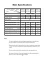
1
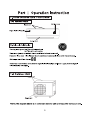
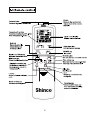
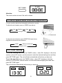
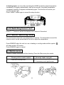
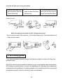
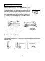
Applicable to
KFR-25GWZ/BM
KFR-35GWZ/BM
KFR-50GWZ/BM
KFR-70GWZ/BM
Split Type Wall-mounted Inverter Room Air Conditioner
Instruction Manual
Thank you for purchasing a Shinco air conditioner.To
guarantee safety and best efficiency, please read this manual
carefully and keep it for future reference.
To Consumers
1. This air conditioning unit should be installed and repaired by a qualified technician.
2. The air conditioning unit must be grounded reliably during the installation.
3. Please clean the air filter nets 1 to 2 times per month when the air conditioner is being used
frequently (details inside).
Features:
With the compressor and the micro computer controlling chip, the performance is
stable and reliable.
The high-efficiency compressor and heat exchanger guarantee higher efficiency
and energy-saving.
Quiet running.
Note:
Some information included in this manual might be different on the unit if parts
are modified by the manufacturer.
1
SAFETY PRECAUTIONS
Please read the SAFETY AND OPERATING INSTRUCTIONS carefully before operating the
unit.
Please respect the following safety precautions when using your air conditioner to
preventfire, shock hazard or personal injury.
WARNING
This sign warns of risk of death or serious injury.
CAUTION
This sign warns of injury or damage to property.
This symbol denotes an action that is PROHIBITED.
This symbol denotes an action that is COMPULSORY.
INSTALLATION PRECAUTIONS
=Do not install, remove or re-install, the unit yourself.
WARNING
Improper installation may cause leakage, electric shock or
fire.
The unit should be installed by a qualified technician.
=Please use ground. Improper grounding could cause elec
tric shock.
Do not place the ground line near water or gas pipes, elec
tric or telephone lines. Improper installation could cause
an electric shock.
CAUTION
Do not install the unit in a place where there could be a
gas leak. The unit may catch fire if flammable gas leaks
around it.
Please ensure smooth flow of water when installing the
drain hose.
The indoor unit must be installed at least 2.4 meters high
from the floor.
If the fuse on PCB board is blown, please have it
changed by aqualified technician.
2
OPERATION PRECAUTIONS
Do not operate with wet hands.
Avoid staying directly in front of operating unit.
Do not insert foreign objects into the unit.
Always have the unit repaired by a professional technician -
WARNING
contact a service center.
Danger of electric shock or fire if used improperly.
Do not use if the power cord is damaged, it could cause an
electric shock or fire.
Do not allow children to operate the air conditioner.
Never sit on the unit.
If you notice an abnormality (burnt smell, etc) please shut
the power off and unplug the unit.
The unit should not be used for any other purpose.
Avoid spilling liquids on the unit.
Do not place the air conditioner close to a heat source, it
CAUTION
could cause a deformation or color fading.
Do not block the air intake and outlet vents.
Do not let the air conditioner function at maximum power for
an extended period of time (close all doors and windows).
Do not operate without the air filter installed or when the
front intake grill has been removed.
Do not place anything on the unit.
Always turn the power off before cleaning the air condi
tionerto avoid any possible accidents.
Please ensure proper ventilation when using the air
conditioner.
3
CONTENTS
To Consumers .......................................................... 1
SAFETY PRECAUTIONS ........................................ 2
OPERATING PRECAUTIONS ................................. 3
2. Batteries ............................................................................................................................. 7
3-1 Setting the clock ............................................................................................................... 7
3-2 Wind Speed-Wind Direction Adjustment ........................................................................... 8
3-3 Timer setting ..................................................................................................................... 8
3-4 Cooling•Heating•Dehumidy mode .................................................................................... 9
3-5 Ventilator mode ................................................................................................................. 9
3-6 Drying clothes mode ......................................................................................................... 9
3-7 Auto running ................................................................................................................... 10
3-8 Powerful mode ................................................................................................................ 10
3-9 Sleeping mode ................................................................................................................ 10
3-10 Switching from Co to F0 ......................................................................................................................................................................... 11
3-11 Sensor Switching mode ................................................................................................ 11
4. Maintenance ..................................................................................................................... 11
5. Efficiency guide ................................................................................................................. 12
6. Trouble Shooting............................................................................................................... 13
Part Installation Instruction.......................... 14
1. Select the location for installation ..................................................................................... 14
2. Installation of Indoor Unit ............................................................................................... 15
2-3 Installation of the Power Source ..................................................................................... 16
2-4 Installation of Drain Hose ............................................................................................... 16
2-5 Arrangement of Pipes ..................................................................................................... 17
3. Installation of Outdoor Unit ............................................................................................... 18
3-1 Flared Joint .................................................................................................................... 18
3-2 Pipe Joint ........................................................................................................................ 18
3-3 Drain Hose ...................................................................................................................... 19
3-5 Installation of the exterior draining pipe .......................................................................... 21
4. TEST RUN ........................................................................................................................ 21
4-1 Pipe-cleaning and vacuum verification ........................................................................... 21
4-2 Test Run Procedure ........................................................................................................ 21
4-3 Instructions to Consumers .............................................................................................. 22
Main Specifications ......................................... 23
4
5
1234567890123456789
1234567890123456789
1234567890123456789
1234567890123456789
1234567890123456789
1234567890123456789
1234567890123456789
1234567890123456789
1234567890123456789
1234567890123456789
6
Directions:
1. Mode display:
(Auto)
(Cooling)
(Dehumidifying)
(Heating)
(Fan)
(Dry clothing)
TEMP
2. Temperature setting display:
3. The temperature around the remote controller display:
4. Wind speed display :
5. Present time display:
(Low)
(High)
(Medium)
(Auto)
TIME
6. Signal transmitting display:
7. Wind direction display:
(Wind direction adjustment)
8. Sensor switching display:
9. Sleep timer display:
10. One hour setting display: 1 HR
11. High power display:
12. Lock display: LOCK
13. Timer setting display:
SET OFF
ON
2. Batteries
Avoid direct sunshine and other heat resources. If the remote control does not function properly, please press the
restart button or change the batteries.
Remove the front cover of the remote control. Please
use two new AAA size 1.5V batteries of the same brand.
Be sure to observe polarity. The batteries should be
taken out of the unit if it is not used for a long period of
time. Never mix new and used batteries.
Two AAA Size 1.5v batteries
Remove front cover
(Change the batteries)
3-1 Setting the clock
Press “SET TIMER”, the minutes indicator will be flashing, then use the arrows to set
the minutes (0~59 minutes) press “SET TIMER” again. Do the same thing to set the
hour (0~23 hours).
7
TIME
SET TIMER
Attention:
The clock can be set even if the unit is closed.
3-2 Wind Speed-Wind Direction Adjustment
For your comfort, adjust the wind speed and direction correctly.
To adjust the wind speed, press on SPEED (see below):
Low
Medium
High
Auto
change in turn
45°
downward
To adjust the wind direction press DIRECTION (see below)
Regulate the horizontal wind direction:
Static
Swing up and down
Change in turn
3-3 Timer setting
To set the starting time press the TIMER button, when ON displays in the time
section on the LCD screen, use the arrows to enter the desired starting time and then
press SET TIME again. The unit will start automatically at the time you have set.
To set the stop time press the TIMER button, when OFF displays in the time
section on LCD screen, use the arrows to enter the desired stopping time and then
press SET TIME again.
The unit will stop automatically at the time you have set.
SET
SET
ON
8
OFF
To cancel time setting press the TIMER button. Nothing will be displayed
on the LCD screen.
One hour setting Press the 1HR button, the one hour setting function is on
(the unit stops after running for 1 hour). To cancel press the 1HR button again.
Note: the values used to display time are from 00:00 to 23:59.
3-4 Cooling•Heating•Dehumidy mode
Press ON/OFF button.
Press MODE button, and choose “Cooling”, “Heating” or “Dehumidify” mode.
Press the arrows to regulate temperatures between 16 and 30 degrees Celsius.
Press the arrows button once, the temperature changes 1 degree at a time.
Press the SPEED button to adjust the air flow.
Press the DIRECTION button to adjust the wind direction.
Press ON/OFF to close the air conditioner.
Attention: If the unit is closed the LCD screen shows the room temperature. The
green light indicates the unit is in cooling or heating mode. The green light will be
flashing when the outside temperature is very cold.
During heating mode, if the exterior temperature is very cold, it is possible that the air
flow could be less powerful and the unit could make some noise and the internal
ventilator could stop. It is also possible that the exterior unit could stop or that some
vapour could evaporate from it, etc. This phenomenon is normal when exterior
temperature is very cold.
3-5 Ventilator mode
Press ON/OFF.
Press MODE, choose the ventilator mode.
Press SPEED, choose the desired speed.
Press ON/OFF to stop the unit.
3-6 Drying clothes mode
Press the ON/OFF button then press MODE button and choose “Drying Clothes” mode.
Press the ON/OFF button to close the air conditioner.
9
Attention:
1. Select the cooling, heating or dehumidify mode according to the room
temperature.
2. If the quantity of clothes to dry is too large or the dehumidify mode is not activated,
then the drying will not be completed.
3-7 Auto running
Choose temperature, wind speed and direction automatically.
Press ON/OFF button then press MODE button and choose “Auto“ setting.
Press TEMP to select the desired temperature and adjust the wind flow and wind
direction.
To close press the ON /OFF button.
3-8 Powerful mode
Press “POWERFUL” in heating or cooling mode and the
symbol
will appear on the LCD screen. Press POWERFUL again to
cancel.
Attention:After operating at maximal power for 15
minutes the unit will automatically stop and then
restartat the preset temperature.
The symbol will disappear on the LCD screen.
The unit will make more noise at maximal power.
3-9 Sleeping mode
Use the SLEEP mode to stay comfortable thru the night, the symbol
the LCD screen. To cancel, press SLEEP again.
will appear on
In cooling mode: one hour after activating the SLEEP mode the preset temperature
increases by one degree automatically, and two hours after the preset temperature increases by one degree automatically again.
10
In heating mode: one hour after activating the SLEEP mode the preset temperature
increases by 2 degrees automatically, and two hours after the preset temperature
increases by another 2 degrees automatically again. This function will assure your
comfort thru the night.
Press SLEEP button again to cancel the sleep function.
3-10 Switching from Co to F0
Press 0C / 0F button to switch the display from Celsius to Fahrenheit.
3-11 Sensor Switching mode
Use this function when the room temperature is uneven. The temperature around the
remote control can be transmitted to the unit to adjust the temperature.
Press SENSOR when the unit is in use in heating or cooling mode and this symbol
will show on the LCD screen.
Press SENSOR again to cancel .
4. Maintenance
Attention: Always unplug unit before cleaning. Clean the filters every two weeks.
Cleaning of the remote control
Clean the intake vent grill
Clean with a damp cloth
Clean with a damp cloth and dry.
If necessary use a gentle soap.
Clean with
soft cloth
11
Clean the air filter (once every two weeks)
1. Hold the two ends of the
grill and gently push the
filters downward
2. Use vacuum cleaner or
water to clean the filters
and then dry.
3. To put the filters back into
place hold the two ends of
the grill and insert the filters.
Intake vent grill
Raise and
insert
Lift and pull
downwards
When the machine will not be used for a long period of time
Run to dry the inside of the machine=Pull out the power plug Take the batteries out
of the remote control.
5. Efficiency guide
Try to keep windows and doors closed. Avoid direct sunlight to indoor unit. Keep the
air filters clean.
Adjust the vertical and horizontal air direction to get a comfortable indoor temperature.
Do not place yourself directly in front of the operating unit. Raising the fan speed can
enhance the cooling efficiency. In heating operation, the humidity level of the room should
be adjusted properly, or the air will be dry and uncomfortable.
12
6. Trouble Shooting
Before calling a repair man, please check the followings:
Symptom
The air conditioner
does not work
Possible reason
•
•
•
•
The unit does not
blow warm air in
heating mode
•
Low efficiency of
cooling or heating
•
•
•
Problem with the remote control.
Problem with the voltage. Please shut the power,
wait 3 minutes and restart the unit.
Verify the circuit breaker or fuse.
The compressor is in a delay mode (to protect the
compressor there are several minutes delay for
every start) wait a few minutes after starting the unit.
The hot air will be blown out only after the defrosting
operation.
The air filters are too dirty.
The intake vent or outlet vent is blocked up.
In heating operation, the ambient temperature is too low.
Defrosting operation may be required.
•
Noise
Abnormality on
the remote control screen
Cold water leaking
from the air conditioner
Water leak noise. It is the sound of the circulation of
refrigerant.
• Condensed air leaking out. In heating operation,
during the defrosting, it is the sound of the back-flow
refrigerant.
• Batteries need to be replaced.
• Batteries are inserted incorrectly. Take the batteries
out and insert them again.
• Moisture will occur in the air outlet due to the tempera
ture difference.
13
Part Installation Instruction
To guarantee the unit it must be installed according to the instructions in this manual.
•
•
•
The air conditioner has to be grounded properly.
Check the connecting cables and pipes carefully, make sure they are correct
and firm before connecting the power of the air conditioner. The maximum
length of the connecting pipe between the indoor unit and outdoor unit should
be no more than 5 metres (or it will affect the efficiency) .
After installation, the consumer must operate the air conditioner according to
the instructions in this manual.
Caution: The installation must be performed in accordance with the National/ Regional Wiring Standard or Code by a qualified technician.
Caution: The indoor unit must be installed at least 2.4m(8ft) above floor or ground
level.
Warning: Risk of electric shock can cause injury or death: Disconnect all remote electric
power supplies before servicing. There must be an air-break switch between indoor and
outdoor unit which needs to be installed close to the indoor unit.
1. Select the location for installation
1-1 Indoor unit
•
•
•
•
•
•
•
Must be placed on a rigid wall with no vibrations.
No obstacle in front of air intake and outlet vents, the distance between the top
of the unit and the ceiling should be at least 10cm (4 inches).
Place unit where the cold air can be blown evenly throughout the room.
The maximum distance between the indoor unit and outdoor unit is 5 metres;
the same distance must be respected for the height.
Avoid direct sunlight. Exhaust water must be easily drained.
The air filter must be installed or removed easily (there should be at least 20
cm of free space under the unit).
The distance between the unit and a television or a radio should be more than
1 metre (because the unit can disturb the images of the television and make
some noise).
14
•
The unit has to be more than 1 metre away from a fluorescent lamp or other
electric bulbs ( they could interfere with the remote control).
1-2 Outdoor unit
•
•
•
•
•
It should be installed in a well ventilated place that is protected from strong
winds.
It should not be exposed to direct sunlight and rain.
It should be installed where the operating noise will not disturb neighbours. It
should be placed on a solid base to avoid vibrations or noise.
Keep away from flammable gas.
If the unit is installed on a raised base make sure it is well secured.
2. Installation of Indoor Unit
2-1Fix the wall-mounted plate
As the unit is heavy, the wall should have sufficient strength and durability for operation
of the air conditioner, and for prevention of any vibration or noise. If it is weak, reinforcement work should be performed prior to installation.
Tie a thin cord in the hole
More than 10 cm
Installation plate
Fix screw ST4 X 30
More than 10 cm
More than 10 cm
The level can be obtained easily by aligning the hanging
cord with the stripe of middle holes
There should be more than 10cm of space all around while installing the indoor unit.
15
2-2 Drill a hole in the wall
•
Select the location.
•
Drill a hole of approximately 6.5 cm diameter
Insert the wall-through sheath into the hole
Hole thru wall
ø6.5 cm
Wall-throughSheath
Indoor
Thickness of wall
2-3 Installation of the Power Source
We recommend that you do not use an extension cord or an adapter plug with this appliance.
Do not change the plug on the power cord of this appliance.
The specification of the power wires and the connecting wires should respect the relative standards,
the AWG size of connection cords between indoor and outdoor unit is 16 and for the power
supply cord it is 14.(the one of KFR-70GWZ/BM is 12.)The connection of the wires must be done
strictly according to the diagrams and connecting marks. Only the same marks can be connected
together. The location of the connecting cables between the indoor unit and outdoor unit must be
out of direct sunlight exposure.
Medium power connecting wire
Indoor unit
Power bar
Warning:
NEVER cut a power wire open. A wrong connection could cause major incidents. Do not use a
damaged supply cord, it must be replaced to avoid an electric shock.
2-4 Installation of Drain Hose
•
•
•
The drain hose should be put below the refrigerant pipe (copper pipe)
Do not bend the drain hose or raise it.
Do not wrap the drain hose too tightly.
16
2-5 Arrangement of Pipes
The drain hose must be put below the copper pipe. Put together the refrigerant pipe, drain hose and the connecting wire
of indoor and outdoor units. Wrap them with binding belt. The
pipes can be arranged towards five directions (back, right, left,
down and left-back). Bind the pipes with binding belt from the
place closest to the elbow (The overlap of the binding should
be 1/2 of the width). Bind the pipes from 1 cm inside of the unit,
if you direct the pipes from the left side.
Front
Right
Back
Down Left back
Left
1cm
Cut off this part
when directing
pipes to right side
Cut off this part
when directing
pipes down ward
Cut off this part
directing pipes
toward left side
Installation of Indoor Unit
Pass the pipes through the wall, hoist the unit on the installation plate and fix the lower
part with a hook.
Installation plate
Attention! Do not
raise the drain hose
Install the wall-through bushing
sheath at suitable place
Wall-through bushing
17
3. Installation of Outdoor Unit
The outdoor unit should be installed on a solid base. (Such as concrete) If it is installed against a brick wall, the thickness of the brick wall should be at least 10cm
deep. If there is a vibration, please install the protective anti-vibration rubber spacer.
Do not install the unit directly on the ground; the base has to be solid and resistant
enough to support the weight of the unit. It has to be firmly fixed. The unit should not
be installed on an angle greater than 50.
When installing the unit, be sure to leave a space of 50 cm in front, more than 10 cm
behind, on top and on the left side of the unit and leave a space of 35 cm on the right
side.
3-1 Flared Joint
You will have a flared joint on both units (indoor and outdoor). As indicated on the diagram, the
refrigerant pipe is used to connect the indoor unit and the outdoor unit.
Outdoor unit
Indoor unit
Refrigerant verification = If the length of the pipe is more than 5m, please refill the refrigerant
(fleon R410A).
Pipe length
less than 5m
need not to refill refrigerant
more than 5m
need to refill refrigerant 50g/m
3-2 Pipe Joint
One of the major causes for a gas leak is due to a defective flared joint, so please verify
the quality of the installation.
18
1. pipe cutting
4. Flare work
Use pipe cutter to cut the copper
Use the follow instruments to undertake
pipe correctly
qualified
Copper pipe 90
flare work.
External diameter(mm)
Unqualified
tilted rugged
Burr
1/4
3/8
1/2
5/8
A(mm)
0.8~1.5
1.2~1.8
1.2~2.0
1.5~2.5
Die
2.remove burrs
Get rid all the burrs of the pipes
Copper pipe
section. Burr
Flare instrumen
yoke die
Connecting
nut
Copper pipe
Copper pipe
5. Check
Pipe cutter
Compare
the flare work with the following
diagrams.
The flared part should be cut off and flared again
if there are some deficiencies of the flare work.
3.install the nut
Remove the connecting nut which is
installed on the indoor unit and outdoor
unit, after rid the pipe of burrs, install it
on the pipe again.
Tilted
Even Broken Rugged
Over flared
Connecting nut
Copper pipe
1. Connection of the indoor unit.
Connect the thick and thin pipes to the indoor unit.
Apply a thin coat of refrigerating oil on the pipes joints. When connecting, screw the
centre and then screw the first 3-4 turns of the connecting nut by hand. Use the wring
torque diagram as the standard of indoor pipe’s connection, use two spanners to tighten
them; over-tightening will damage the flared joint .
External diameter(mm)
Wring torque(kgfcm)
1/4
150~210
3/8
380~450
1/2
400~460
5/8
500~575
2. Connection of outdoor unit.
Proceed the same way as the indoor unit.
Connect the pipes with the outdoor unit’s valve. Use a spanner to grip the
valve and use the torque spanner to grip the connecting nut.
Connect the pipe to outdoor unit with the same wring torque as used for the
indoor unit.
Caution: Proper insulation thickness. If the insulation is too thick, it could cause an
accumulation of water behind the indoor unit. If the insulation is too thin it could cause
moisture and water dripping.
3-3 Drain Hose
To drain the water, please incline the drain hose downwards (diagram 1). Do not install
as shown on diagram 2~5.
19
Do not raise the
drain hose
Incline
downward
air
Dripping (2)
(1)
Drainage retention
Dripping
The end of the
drain hose is
dipped into water
Wave
Dripping
(3)
(4)
The distance between the
hose end and the ground is
less than 5cm
(5)
If the drain hose installed on the indoor unit is not
long enough, please connect as shown on the diagram to your right.
If the drain hose needs pass through indoors, please
wrap it with heat insulation materials which are available at your local hardware store.
3-4 Electric wire connection
Intdoor Evaporator
Outdoor Encloser
Indoor Electric parts
Outdoor Electric parts
L3
L4
S
G
L1
L2
G
Air-break switch
Air-break switch
L3
L4
S
G
Power supply
Outdoor Electric parts
Outdoor Encloser
The installation must be done as indicated on the diagram, connect the power wires
according to the stipulated order and colors.
The power wires between the indoor unit and the outdoor unit must be corresponding
with each other (colour, order and diameter) The yellow-green
wire is the grounding wire, it must be connected to an adequate electric power socket or it could cause
an incident.
After installation, the wires must be pressed tightly with the wire clip.
Make sure the wires are attached solidly by pulling gently.
If the connecting wires are not long enough replace them with wires of same diameter
and color.
Warning: The wires must be connected properly otherwise it could cause a short circuit.
20
3-5 Installation of the exterior draining pipe
Insert the drainage pipe into the hole of the base, connect an extending pipe to drain the
water.
Base hole of the outdoor unit
catchment trough
4. Test Run
4-1 Pipe-cleaning and vacuum verification
Make sure all the pipe joints have been screwed tightly, then clean the pipes and verify
the vacuum.
Remove the valve core copper caps of the high pressure valve and the low pressure
valve.
Remove copper cap of refrigerant-adding valve, measure the vacuum with the vacuum
pump (value should be less than 10Pa)
Close the copper cap of refrigerant-adding valve.
Unscrew the high pressure valve and low pressure valve.
Use the leakage detector or soapy water to check the system pipe joint and valve cap for
leakage.
If there is no leakage, screw tightly the copper caps of valve cores .
4-2 Test Run Procedure
Before testing, please check all the connecting wires and pipes carefully to see if they
are correctly connected, verify if the stop valve is completely opened or closed, and if
the air conditioner has been grounded correctly.
Connect the air conditioner system to the power source, a “Du” sound emitted by the
indoor buzzer should be heard.
Turn the air conditioner ON with the remote control.
Please choose the “heating” mode and set temperature at 25 0C to check the heating
function. Please choose the “cooling” mode, set temperature at 160C to check the
cooling function
21
Remark
Check the following items according to the related contents of this manual.
Indoor unit :
Is the noise abnormal?
Does every indicating lamp function normally?
Does it drain smoothly?
Outdoor unit:
Is there abnormal noise or vibration when it is running?
Does the noise and water drainage disturb the neighbours?
Is there a gas leak?
The remote control:
Do all the function keys work normally?
When transmitting the signal, does the indoor unit emit a “Du” sound?
4-3 Instructions to Consumers
After installation, the service technicians are required to:
Explain the operation methods, the key functions, and any other information included in this
manual.
Explain how to remove and install the filters and how to control the wind direction.
How to place the batteries in the remote control.
Advise the consumers to read this instruction manual carefully before operation, and answer the
consumers’ questions.
22
Main Specifications
Data
Model
Item
KFR-50
KFR-25 KFR-35
KFR-70
GWZ/BM GWZ/BM GWZ/BM GWZ/BM
Type
Cooling & Heating
Cooling Capacity
(Btu/h)
9000
12000
18000
24000
Heating Capacity
(Btu/h)
10400
13650
19100
27000
Rated Voltage
(V)
230
Rated Frequency
(Hz)
60
Rated Cooling Power Input
(W)
765
1075
1670
2400
Rated Heating Power Input
(W)
880
1160
1720
2550
24/77
24/95
35/112
37/150
(m3/h)
450
500
800
1200
Design Pressure of High Side (PSI)
500
500
500
500
Design Pressure of Low Side (PSI)
250
250
250
250
Mass:indoor unit/outdoor unit (lbs)
Air Flow:indoor unit
Refrigerant:type/quantity
(lbs)
R410A/1.85 R410A/2.1 R410A/2.9
R410A/4.2
Note:
The above mentioned cooling and heating capacities are standard and
may vary slightly in accordance with the ambient temperature.
Please use the unit for heating when the outdoor temperature ranges from
–70C to 430C and for cooling when outdoor temperature ranges from 180C
to 430C.
The air conditioner should be connected to its own separate circuit.
No notice will be given if there are changes in the data, please take the
data on the unit’s name plate as the standard.
23
Serial No.: eb45493
Version:090318