1
Safety
Information
Precautions
FCC Information
Please read this manual carefnlly before using your Monitor and
keep the manual handy for future reference.
•
WARNING
TO PREVENTFIRE OR SHOCK HAZARDS, DO NOT
EXPOSE TEllS UNIT TO RAIN OR MOISTURE.ALSO 110
NOT'USE THIS UNIT'S PLUG WITH AN EXTENSION
CORD RECEPTACLEOR OTHER OUTLETS,UNLESSALL
PRONGS CAN BE FULLYINSERTED. REFRAINFROM
OPENING THE CABINET AS THERE ARE HIGIq-VOLTAGE
COMPONENTS INSIDE. REFERSERVICINGTO QUAI,IFIED
SERVICEPERSONNEL.
Industry
Canada Compliance
Notice
This Class B digita! apparatus meets all requirements of tilt'
Canadian Interference-Causing Equipment Regulations
Declaration of Conformity
This de_ice complies with Part 15 of the FCC rules. Operatkm is
subject to tile following two conditions: (1) This device may not
cause harmful interference, and (2) this device must accept any
interference received, including interference that may cause
undesired operation.
Product: Cinenm Screen I)isplay
FCCRegulationsstatethat unauthorizedchangesor
modifications to this equipment may void the user's authority
to operate it.
This equipment has been type tested and found to comply
with the limits tk/r a Class B Digital Device in accordance
with the spccificatiuns in Part 15 of the FCC rules. These
rules are designed to provide reasonable protection against
radio and television interference in a residential installation.
This equipment generates and can radiate radio flequency
and. if not installed and used in accordance with the
instructions, may cause harmful interference to radio
con_munications. However. there is no guarantee that
interDrence _,ill not occur in a particular installation.
If this equipnlent does cause interference to the radio or
television reception (which you can detennine by turning the
equipment off"and on). try,to correct tile interference by one
or
nlore
•
of the
lk)lk)wing
nleasures:
Reorient or relocate the receiving antenna (.that is.
the antenna for the radio or television that is
"receMng" the interterence/.
Change the position
the radio or television
tile interference.
of the monitor with respect
equipment
to
that is receiving
Equipment Cl:tssification: Class B Conlputer Periphera[
Model: PHI)=,0300
Mo_e tile monitor away fron/ the cquipnlent
receiving tile intcrlc+rence.
\x:_,hereby declare that the equipment specified above contorms to
the technical smndaMs as specified in file FCC iT.des.
I)lug tile
inonitor
receiver
and
Thon/son multin/cdia Inc.
10330 N. Meridian St.
Indianapolis. IN i6290
PIione: 1-800 133-8974
Cable "ry Installer: This renlinder is ptovided to call )our
attention to Article 820-40 of the National Electrical Code tScctiun
"_t ot tile Canadian Electrical Code. Parl 11 xxhich pro\idcs
guidelines Ic_r proper grounding and, in ['nuticulaL specifics that
tilt' cah[e gruutld s]/a][ he c(/nnccted 1o lhe grounding s}rstelll of
t]lC huildh/g
as cIosc tl) IIle poi[/t ot cable enlQ :is practical
into a dilf_'rent
the equipment
wan
outlet
arc on cliCk:rent
so the
hnlnch
circuits.
If these n/ensures do not eli[llinale intcl-lE.rence,please
consuh your dealer or an experienced radio television
technician lor additional suggestions Also. tile Fedend
('omnltmkati{_ns Commission has prepared a helpful
hooklet. "tIo;x 1o Identify and Resolxc Radio TV Inlerfcrence
Iqoblenls." This hooklcl is a',ailahle fiom the US.
Go_crnnlcra Prmth/g Office. Washington D C., 20t02. Please
specif} stock ntln/l)t.+r 004 0011-1)034q-t when ordering copies.
Warnings
and Safety Precautions
The monitor is designed and manul_ctured
to provide
long, trouble-free service. No maintenance other than
cleaning is required. Use a soft dry cloth to clean the
panel. Never use solvents such as alcohol or thinner to
clean the panel surface.
The display panel consists of fine picture elements (cells).
Although the display panels are produced with more than
99.99 percent active cells, there may be some cells that do
not produce light or remain lit.
For operating safety and to avoid damage to the unit, read
carefully and observe the following instructions.
To avoid shock and fire hazards:
1.
Provide adequate space for ventilation to avoid
internal heat build-up. Do not cover rear vents or
install in a closed cabinet or shelves.
The unit is equipped with cooling fans. If you install
the unit in an enclosure, be sure there is adequate
space at the top of the unit to allow hot air to rise and
escape.
IMPORTANT TIPS: Caring for Your
Monitor
To avoid
Do not use the power cord plug with extension cords
or outlets unless all prongs can be completely inserted.
3.
Do not expose
4.
Avoid damage to the power cord, and do not attempt
to modify the power cord.
.
6.
7.
operating
life:
Use only with 120V 50/60Hz AC power supply.
Continued operation at line vohages greater than 12(1
Volts AC will shorten the life of the unit, and might
cause a fire hazard.
2.
Handle
3.
Locate set away from heat, excessive
sunlight.
4,
Protect the inside of tire trait from liquids and small
metal objects. In case of accident,
unplug the unit and
have it serviced
by an authorized
service center.
5.
Do not hit or scratch the panel surface as this causes
flaws on the surface of tire screen.
6.
For correct installation and mounting it is strongly
recommended
to use a trained, attthorized dealer.
7.
Like all phosphor-based
display devices, monitors can
be susceptible to uneven phosphor aging under cellain
circumstances. Certain operating conditions, such as
the continuous display of a static image over a
prolonged period of time, can result in uneven
phosphor aging if proper precautions are not taken. To
protect your investment in this monitor, please adhere
to the following guidelines and recommendations
for
minimizing the occurrence of uneven phosphor aging:
persists, contact your dealer for service.
2.
and prolong
1.
If the monitor becomes too hot, the overheat protector
will be activated and the monitor will be turned off. If
this happens, turn off"the power to the monitor and
un-plug the power cord. If the room where the
monitor is installed is particularly hot, move the
monitor to a cooler location, and wait for the monitor
to cool for 60 minutes.
If the problem
damage
the unit carefully when installing it.
dust, and direct
Always enable and use your computer's screen saver
function during use with a computer input source.
Display a moving image whenever
possible.
unit to water or moisture.
Always power down the monitor when you are
finished using it.
If viewing with a 4/3 aspect ratio for long periods of
time, set side gray level at 3 or 4.
Unplug unit during electrical storms or if unit will not
be used over a long period.
Do not open the unit which has potentially
high voltage components inside. If the unit
from opening the cabinet the warranty will
Moreover, there is a serious risk of electric
dangerous
is damaged
be void.
shock.
If the monitor is in long term use or
continuous operation take the following
measures
to reduce
phosphor
aging:
Do not attempt to service or repair tire unit. Tmnr is
not liable R)r any bodily harm or damage caused if
unqualified persons attempt service or open the back
cover. Refer all service to authorized Service Centers.
the likelihood
of uneven
Lower the BRIGHTNESS and CONTRAST levels its
much as possihle without impairing image readability.
Display an image with many colors and color
gradations (i.e. photographic
or photo realistic
images).
Create image content with minimal contrast betv, een
light and clark areas (fi)r example, white characters on
black backgrounds).
Use complementary
or pastel
color whenever possible.
•
Avoid displaying images with t)w colors and dislinct.
sharply defined borders between colors.
Contents
Safety
Information
...................................................................................
1
Warnings and Safety Precautions .............. _....................................................................
2
IMPORTANT TIPS: Caring for Your Monitor ...................................................................
2
Getting
5
Started
.........................................................................................
Contents of the Package ..................................................................................................
6
Part Names and Functions-
Front View .........................................................................
7
Part Names and Functions - Back View ..........................................................................
8
Battery Installation ...........................................................................................................
9
Connecting an HD Receiver .............................................................................................
The Back of the HD Receiver .....................................................................................
9
9
Connecting Your VCR Or Laserdisc Player .....................................................................
10
Connecting Your DVD Player .........................................................................................
10
Connecting a Personal Computer ..................................................................................
10
Connecting Components to the Monitor ......................................................................
11
Connecting External Speakers to the Monitor .............................................................
A Quick Tour of the Remote Control .............................................................................
12
13
Using Your Remote Control .....................................................................................
Inserting Batteries ..............................................................................................
Programming the Remote .......................................................................................
Find Out If You Need to Program the Remote ................................................
How to Program the Remote ............................................................................
Using Automatic Code Search ...........................................................................
Using Direct Entry ..............................................................................................
How To Use the Remote Control
15
15
15
15
16
16
t7
After You've Programmed It ...................................................................................
Programmable Codes for the Remote Control .......................................................
t7
18
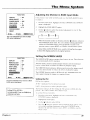
The Menu System ...................................................................................
21
Basic Operations .............................................................................................................
Power ........................................................................................................................
22
22
Volume ......................................................................................................................
Mute ..........................................................................................................................
22
22
Navigating the Menus .............................................................................................
The Multi-Screen Feature ........................................................................................
Selecting the Input Signals to be displayed .....................................................
On-Screen Menu Operation ....................................................................................
The PICTURE QUALITY Menu .........................................................................................
Setting the Picture Mode .........................................................................................
Adjusting the Picture Settings in MEMORY Mode .................................................
Setting the Color Temperature ................................................................................
Reducing Noise in the Picture .................................................................................
The AUDIO Menu ............................................................................................................
22
23
24
24
2S
25
26
27
28
29
The SCREEN Menu ..........................................................................................................
30
Selecting a Viewing Size ..........................................................................................
Adjusting the Picture Position and Size ..................................................................
Auto Picture ..............................................................................................................
30
31
31
Contents
The FUNCTION Menu ......................................................................................................
32
On-Screen Displays ...................................................................................................
Adjusting the Position of the Menu Display ..........................................................
Setting the POWER SAVER for Computer Images ..................................................
The POWER/STANDBY Indicator ..............................................................................
32
32
33
33
Setting the Gray Level for the Sides of the Screen ................................................
Adjusting for Flickering with Film Mode ................................................................
34
34
Adjusting the Display in RGB3 Input Mode ............................................................
Setting the Screen Saver ..........................................................................................
Setting the PLE...................................................................................................
Turning Orbiter On ............................................................................................
Setting the Inverse .............................................................................................
Resetting to Default Values .....................................................................................
The OPTIONS Menu ........................................................................................................
Setting the Audio Inputs .........................................................................................
Setting the BNC Connectors ....................................................................................
Setting a Computer Image to the Correct RGB
Select Mode .....................................................................................................
Setting the Monitor to the correct
HD Receiver Mode ...........................................................................................
35
35
35
36
36
37
38
38
38
39
40
Setting the Picture Size for RGB input signals ........................................................
The SETUP Menu .............................................................................................................
40
41
Confirming the Frequencies, Polarities, mode
and resolution of Input Signals .........................................................................
Selecting the Language for the Menus ..................................................................
Setting the Video Signal Format .............................................................................
41
42
42
The AUTOTUNING
SETUP Menu ....................................................................................
43
Autotuning the Component Buttons on he Remote Control ................................
SLEEPTIMER ....................................................................................................................
43
44
Setting the Sleep Timer ............................................................................................
Cancelling the Sleep Timer ................................................................................
44
44
Other
Information
..................................................................................
45
Installing the Monitor ....................................................................................................
Attaching optional mounts or stand to the Cinema
Screen monitor ......................................................................................................
46
Connecting Your PC Or Macintosh Computer ..............................................................
Mini D-sub 15 Pin VGA Signal Composition ...........................................................
Specifications ..................................................................................................................
47
47
48
Troubleshooting ..............................................................................................................
49
The Monitor Menu System ............................................................................................
Supported Resolution ....................................................................................................
50
52
RCA Limited Warranty ....................................................................................................
54
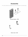
Accessories ......................................................................................................................
56
Index ................................................................................................................................
57
46
I_ HAPTER
Connections
and Setup
Chapter
Overview:
•
Contents
of the Package
•
Part Names and Functions
•
Battery Installation
• Connections
• A Quick Tour of the Remote
Control
1
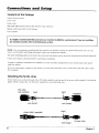
Connections
Contents
Cinema
,_creen
Power
cord
Ferrite
cores
and
Setup
of the Package
monitor
RGB cable (Mini D-Sub 15-pin to Mini D-Sub 15- pin connector)
Remote control unit with two AA batteries
User's manual
It is highly recommended
that you have your monitor
the monitor yourself, refer to the Reference section.
installed
by a professional.
If you are installing
NOTE: If you are planning on attaching tile floor stand to your monitor (and not the optional wall mount unit) you may
want to use the safety metal fittings (provided) to give your monitor extra stability.
The safety metal fittings attach to the back of the screen and can then be used to secure the monitor to the wall with strong wire.
Contact your trained, authorized
In order to conform
cable (see below).
If you are connecting
FCC standards.
Attaching
to mandatory
a computer
dealer for professional
FCC standards,
installation.
you must attach the supplied
ferrite cores to both ends of the power
to the monitor, you must attach the ferrite cores to both ends of the DVI cable to meet
the ferrite cores
Set the ferrite cores on the both ends of the DVI cable (supplied), and one end of the power cable (supplied).
tightly until the clamps click. Use the band (supplied) to secure tbe t;errite core.
Close the lid
DVI cable
(not supplied)
band
core (small)
power cable
(supplied)
band
connector
core (small)
band
(monitor
side)
core (large)
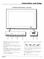
6
Chapter
1
Connections
Part Names
and Functions
and
Setup
- Front View
t
I
VOLUM!
iNPUT •
MEnu°OK - If no menu is displayed,
menu. If a menu is displayed,
press
highlighted
option.
2.
VOLUME
--
Adjusts
the
volume. When
menu is being displayed,
(A and V).
3,
to
brings up the
select a
an
GoBACK
4.
VIDEO2 _
RGB2**_
VIDEO3 _
CMPNTI*
RGBI _
CMPNT2
1
moves hig.hlight up and down
\Vilen a menu is being displayed,
through menu (._ and _. ).
t\_;l(,.
}oft can set zip (=IllPI_T1 or RGB2,
When an on-screen
you to the previous
menu is being
menu.
but .or
displayed,
both.
returns
I_OWER/STANI)BY indicator - When the power is on,
the 1 _ 1 is green. When the powvr is in Standby
\lode, tile light is red.
used to navigate
(}.
1
INPut • Go BaCK Switches tile input, in tire i'ollowing
order:
_.VIDEO1 _
RGB3 _
oil-screen
LEFT/-ANDRIGHT/- - When Zoom mode is on (press OK
oil tile remote to turn ZOOM on and bFing up tile
zoom icon) press Right/+ to enlarge the image or I.eti to reduce tile image.
Chapter
POWER• STANDIY
i
Turns
the
tllonitor's
power
on
and
off.
7
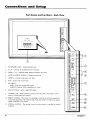
Connections
and
Setup
Part Names and Functions - Back View
RIGHT
e
LEFT
@ @ @
t
A
--3
I
®
I
I
1.
, ®
EXTSPEAKERL and R - Connect speakers here.
I
I
2.
AC IN - Connect
the included
3.
VIDEO 1, 2, 3 - Connect VCRs, DVDs, Laserdiscs, etc. here.
4.
AUDIO1, AUDIO2, AUDIO3 - Connect audio here.
5.
CMPNT1 - Connect
6.
RGB1 - Connect HD receiver here.
7.
BNC SELECT-
I
power cord here.
Laser discs, etc. here.
I
I
I
RGB2: Inputs the analog RGB signal.
CMPNT2: Connect DVDs, Laserdiscs, etc. here.
I
I
I
I
8.
RGB3 (DVI 29pin) - Inputs a digital RGB signal.
9.
CONTROLLOCK When CONTROL LOCK is in the ON position, the buttons on the
monitor's control panel don't function.
®
10. REMOTE CONTROL - This jack is for connecting a wired remnte, which is primarily _'br
commercial applications. The remote included with your monitor is wireless and doesn't
require connection to the monitor.
®
®
J
11. EXTERNALCONTROL - This terminal is used when the nronitor is controlled by external
equipment.
8
®
Chapter1
Connections
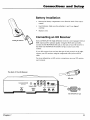
Battery
Setup
Installation
Remove the battery compartment
control.
•
Insert batteries.
correctly.
•
Replace cover.
Connecting
Installingthe batteries
and
cover from the back of the remote
Make sure the polarities
(+ and -) are aligned
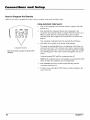
an HD Receiver
RCA and PROSCAN HD (high definition) receivers come equipped with an
RGB output jack for optimum quality. Using the RGB cable provided,
connect the HD MONITOR OUT jack on the back of your HD receiver to
the RGB1 (HD MONITOR IN)/AUDIO1 IN jack on the back of the
monitor.
If your HD receiver does not have the type of jack pictured on the right,
connect your HD receiver using the component video jacks and RCA
cable.
For more information
user's manual.
on HD receiver connections,
see your HD receiver
The Back of the HD Receiver
RGB cable
HD MONITOR OUT jack
Chapter
1
9
Connections
and
Setup
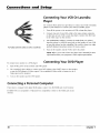
Connecting Your VCR Or Laserdisc
Player
Use common RCA cables (not provided) to connect your VCR or laserdisc
player to your monitor. To connect your VCR or Laserdisc player:
1.
Turn off the power to the monitor and VCR or laser disc player.
2.
Connect one end of your RCA cable to the video output connector
on the back of your VCR or laser disc player. Connect the other end
to the video input on the monitor.
,
RCAcables (audio/videocables)are sold as a bundled set.
4.
Use standard RCA cables to connect the audio from your VCR or
laser disc player to AUDIO2 input jacks on the monitor (if your VCR
or laser disc player has this capability). Be careful to keep your right
and left channel connections correct for stereo sound.
Turn on the monitor and the VCR or laser disc player.
NOTE: Refer to your VCR or laser disc player user's manual./br more
information about your equipment's tJideo output requirements.
To connect
Connecting Your DVD Player
your monitor to a DVD player:
1.
Turn off the power to the monitor and DVD player.
2.
Use a standard video cables to connect your DVD player to the CMNT1 input on the monitor,
or use the DVD player's S-Video output. (Use a standard S-Video cable to connect to the SVideo input on the monitor.)
3.
Turn on the monitor and the DVD player.
Connecting
If you have a computer
a Personal
with digital RGB output,
For IBM VGA (or compatible)
monitor.
10
Computer
or Macintosh
connect
(or compatible)
it to the RGB3 jack on the monitor.
connect
to the RGB1 jack on the
Chapter
1
Connections
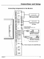
Connecting
Components
....
//
/
.,,,,,o...,
........
VIDEO
and
Setup
to the Monitor
,,
1
VIDEO 2
/
i
VIDEO 3
/
LIMONO)
/
VCR or Laser Disc Player
R
/
0B
D I
I
DVD Player
LIMONOl
Zl
Signal cable (supplied)
To Mini D-Sub15 pinconnectoronthe
PlasmaSync 4210W
RGB 1
I
°1
I
CRII PR
Y IIY
IBM VGA or Compatibles
CBII P_
YNC
\
ENC
I
i
\
LIMONOI
R
\
\
Macintosh or Compatibles
RG_ 3
DIGITALRG8
Personal computer with a digital RGB output
\
\
CONTROL
LOCK
\
\
onJ_. off_=-
x
\
\
REMOTE
CONTROL
\
1
___
Monitor adapter for Macintosh
\
Chapter
,'
EXTERNAL
CONTROL
11
Connections
and
Setup
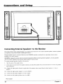
Connecting External Speakers* to the Monitor
The monitor doesn't have internal speakers, so in order to get sound you must connect
can reproduce sound from VIDEO or RGB signal sources.
External speakers may be connected
amplifier to the audio outputs.
external
speakers,
directly to the SPEAKERS terminals or indirectly by connecting
External speakers
a stere{) system
CAUTION: Unplug the monitor and all connected components before connecting external speakers, Use only speakers
with 6 to &ohm impedance and a power output rating of 7 watts or more.
To connect
external
speakers
directly to the monitor:
1.
Strip the ends of the speaker
wires.
2.
Press down the tabs below the speaker terminals
wire connection.
[a]
Connect the right speaker
RIGHT +.
(located
[b]
Connect
the right speaker
[c]
Connect
the left speaker negative
[d]
Connect
the left speaker
and insert the speaker
wire and release the tab to secure the speaker
at right side of the monitor when viewed
from the front) positive (+) ,.',ire to
negative (-) wire to RIGHT -.
(-) wire to LEFT-.
positive wire (+) to LEFT+.
*'Not included
12
Chapter
1
Connections
and
Setup
A Quick Tour of the Remote Control
VCR1
DVD
ON*OFF
VCR2
MONITOR
AOX DDRSVR
&&°&&
MUTE
WHO'MULTI
@
zOOM/N
@
@ OOMO
©
SLEEP
In alphabetical
order
ANTENNA When the remote is in HD RCVR mode, switches the HD
receiver between Antenna A and Antenna B.
Arrows
Use the arrows to navigate through
the Zoom pointer in Zoom mode.
the menu screens and moves
AUX (auxiliary) You can program this button to control any one of the
following: a cable box; most GE, RCA, and PROSCAN audio components;
a laserdisc player; a VCR; or a satellite receiver. Press this button to
operate the component you've programmed to work with the AUX button.
GO BACK
GUIDE
_
INFO
CH+/CHChanges channels on the HD receiver when the remote is in
HD receiver mode. When the Zoom mode is active, zooms in (CH+) or
out (CH-).
CINENA Press to select one of four screen sizes to suit the type of input
you're watching.
MENU
CLEAR
,0,0
'0
,0,0,0
INPUT
REVERSE
CLEAR Clears on-screen
©
PLAY
STOP
CMPNT1 and CMPNT2 inputs.
GO BACK In HD receiver mode, returns you to the previous channel.
When in the menu system, returns you to the previous menu.
FORWARD
GUIDE
RECORD
displays and returns you to normal viewing.
CMPNT Toggles between
ANTENNA
©°0
NOTE: When watching the HD receiver, screen size is controlled
through the HD receiver menu system.
In HD receiver mode, brings up the on-screen
program guide.
PAUSE
INFO
CINEMA ROB CMPNT VIOEO
OO00
L____ SOURCE
Brings up channel
INIrtyr
Changes
information.
the video input.
MENU Brings up the on-screen
menu.
MONITOR Turns the power to the monitor on and puts the remote in
Monitor mode so you are able to control the monitor.
MUTE Reduces sound to an inaudible
Numbers
Use the number
level.
keys to make numerical
entries.
OK/ZOOM
When in Monitor mode (press the MONITOR button) and
using on-screen menus, press OK to select a highlighted menu function.
When there are no on-screen menus displayed, press OK to bring up the
zoom pointer. Using the arrow buttons, position pointer on the part of the
screen you want to zoom on, then use the CH+/- buttons to zoom in/out.
Chapter1
13
Connections
VCR1
DVD
and
OR-OFF
VCO2
MORITOR
AOX HDRCVR
&
MUTE
WHO"MULTI
Setup
ONeOFF Toggles power on and ()ft 12)rthe components that you have
programmed. For example, if you are in VCR mode, turns VCR on and
off.
REVERSE, PLAY, FORWARD, STOP, PAUSE, RECORD (transport
keys)
Use with components
programmed
to work with your remote control
(VCR, DVD player, audio components).
RGB Depending on how you set up the monitor, toggles between
RGB2*, and RGB3.
RGB1,
*Note: You can set t@ CMPNT2 OR RGB2, but not both. lf CMPNT2 is
set up, RGB2 will not appear when you use the RGB button.
ZOOM
O_
SLEEP
GO BACK
GUIDE
INFO
0
_/_
_OK_
?_.
MENU
SLEEP Brings up the sleep timer, which is used to turn the monitor off
automatically after a set amount of time.
VCR1, VCR2, DVD, HD RCVR,
buttons used to put the remote
that particular component. The
(VIDEO or RGB) or Autotuning
CLEAR
'0
VOL</VOL>
VIDEO
inputs.
7(_8_
ANTENNA
REVERSE
PLAY
RECORD
STOP
=
ROB
r_
L
14
FORWARD
CMPNT
PAUSE
VIOEO
=,
SOURCE-----J
Adjusts the w)lume.
Selects whatever
WHO*MULTI
INPUT
CINEMA
MONITOR These are the component
control into the correct mode to operate
correct video source must first be selected
must be set up.
component
is hooked
up to the video source
When in Monitor mode. activates the multi-screen
feature.
The Multi-screen feature allows you to select a screen mode for viewing a
single picture, side-by-side pictures, or picture-in-picture
(PIP). Brings tip
personal viewer profiles for sonle components.
ZOOM IN When in zoom mode (press the MONITOR button an then
the OK button to access zoom mode) enlarges the picture. When in zoom
mode, use the arrow buttons to pan and scan the entire picture.
ZOOM
OUT
When
in zoom
mode/prcss
the MONITOR
button
the OK button to access zoom mode) decreases
the magnification
picture. If picture is distorted,
ZOOln out to restore to llorma]
an then
of thE:
Chapter
1
Connections
Using Your Remote
Inserting
and
Setup
Control
Batteries
1.
Remove tire battery compartment
2.
Insert batteries (included)
conrpartnrent.
3.
Replace the battery compartment
cover from tire renrote control.
as shown on the diagram inside the battery
cover.
Use your remote control from a distance of about 7m/23 feet from the
monitor's remote control sensor and at a horizontal angle of within 30 °.
The remote operates on line of sight, so if there is anything blocking the
path between the remote and the remora control sensor on the front of
the monitor, the remote may not work.
Installing the batteries
•
Don't expose the remote control sensor on the front of the monitor
to direct sunlight or strong artificial light.
•
Don't get the remote control wet.
Avoid heat and humidity.
When not using tire renlote
batteries.
Programming
for a long period of time, remove the
the Remote
The universal remote control that came with your monitor is already
programnred to operate most RCA, GE, and PROSCAN VCRs, DVD
players, laserdisc players, and satellite receivers. This remote is also
capable of operating many other brands of remote-controllable
electronic
components, but you must program it to do so.
Find Out If You Need to Program
t
Approx.
7m/23 ft.
....
the Remote
To determine whether the universal remote needs to be progranrmed,
turn on one of your componems, such as a VCR. Point the renlote control
at the component and press the component button (for example, the VCR
hutton). Now press the ON.OFF button on the remote. If the component
doesn't turir off. you need to program the remote control in order for it to
operate that component.
c
.:il
Chapter1
15
Connections
and
Setup
How to Program the Remote
There are two ways to program the remote
control: automatic
code search and direct entry.
Using Automatic
1.
Turn on the component
receiver, etc.)
2.
Press and hold the component button that corresponds to the
component you want the remote to operate (VCR, HD receiver, etc.).
While you hold down the component button, press and hold
ON-OFF (when the red light on the remote turns on, release both
buttons).
Note.. Automatic
3.
Component
Code Search
you want the remote to operate
(VCR, HD
Code Search can't be used with the A UX button.
Press PLAY (the red light on the remote starts flashing).
The remote is searching the first set of component codes (there are
several sets of codes). If the component you want to operate doesn't
turn off automatically after 5 seconds, press PLAY again (the red light
starts flashing again as the remote searches through the next set of
codes).
Buttons
Theseare the buttons you program to operateanother
component.
Continue
pressing
PLAY until the component
turns off.
NOTE: If the component doesn't turn off after you 're pressed the PLAY
button 20 times, the component can't be programmed.
4,
5.
16
Press REVERSE and wait 2 seconds.
component turns back on.
Repeat this step until the
To finish, press and hold the STOP button until the red light on the
remote turns off.
Chapter
1
Connections
and
Setup
Using Direct Entry
1.
Turn on the component
you want the remote to operate (the red light on the remote turns
on).
2.
Look up the brand and code number(s)
pages.
for the component
on the code list on the following
3.
Press and hold the component button that corresponds
to operate (VCR, RCA DVD, etc.).
4.
Enter the code from the code list. When you begin entering numbers, the red light on the
remote rams ofT. When the last number is entered, the red light turns back on. If the incorrect
code is entered, the red light will flash.
5.
Release the component
6.
Press ON-OFF to see if the component responds to the remote commands.
pressing the component button and then ON-OFF again.
6.
If you get no response, repeat these steps using the next code listed for your brand, until the
component responds to the remote commands.
to the component
you want the remote
button. The red light on the remote turns off.
If it doesn't,
How To Use the Remote Control After You've Programmed
Once the remote control has been programmed
other components.
successfully,
try
It
you're ready to use it to operate
1.
Press one of the video source buttons to select a component
2.
Press the component button (MONITOR, VCR, DVD, AUX, or HD RCVR) to use the Transport
buttons (REVERSE, PLAY, FORWARD, STOP, PAUSE, and RECORD) to operate the component.
3.
Press ON-OFF
to turn the component
(VIDEO or RGB) to operate.
on or off.
NOTE: If you keep pressing buttons and nothing happens, you may have the wrong video
source or wrong component selected. You must select the correct video source and the
component button that matches the component you want to operate.
Chapter
1
17
Connections
and
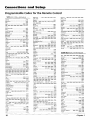
Programmable
VCR
Setup
Codes for the Remote Control
(VCR1, VCR2 or AUX button)
Akai 2003, 2004, 2005. 2007, 2008, 2111, 2112,
2113
Magnavox
.......... 2021,2022,2062,
2063, 2104,
2108,2124
Magnin ........................................................
2013
Marantz...,2009,
2010,2011.2016,2018,
2021,
2058, 2062,2064
Mama ...........................................................
2014
Masushita ....................................................
2021
MEI ...............................................................
2021
American High ............................................
Asha .............................................................
2021
2013
Memorex ............ 2002.2011,
2023,2026,2104,2131
Audio Dynamics ................................
2009.
Audiovox .....................................................
Bell & Howell ..............................................
8eaumark ....................................................
2010
2014
2011
2013
MGA ........................................
2029, 2065,
MGNTechnology
........................................
Midland .......................................................
Minolta ....................................
2055, 2056,
Admiral ......................................................
Adventura
...................................................
2131
2026
Aiko .............................................................
2027
Aiwa ..................................................
2002,2026
2013.2014,
2021,
2113
2013
2053
2107
Sylvania ....2002, 2021, 2022, 2026, 2062,2063.
2065,2124
Symphonic .........................................
2002, 2026
Tandy .................................................
2002, 2011
Tashiko ........................................................
2014
Tatung ...............................................
2058,2111
TEAC .................... 2002,2026,2058,2085,2111
Technics .............................................
2021, 2109
Teknika ......2002, 2014, 2021, 2028. 2100, 2129
TMK .........................................
2013, 2024. 2047
Toshiba2015.2049,2051,2055,2065,2093,2116
ToteVision ..........................................
2013,
Unitech ........................................................
Vector Research ............ 2009. 2010.2015,
Victor ...........................................................
2014
2013
2016
2010
Video Concepts,..2009,201_
2015.2016,
Videosonic ...................................................
2113
2013
Broksonic ...........................................
2012, 2025
Calix .............................................................
2014
Candle2013, 2014, 2015,2016, 2017, 2018, 2019
Mitsubishi ........... 2029.2055, 2056.2065,
2067,2069,2070,2071,2072,2073.2074,2106,
2113,2123
Canon
Montgornery
Ward ........................... 2075, 2131
Motorola
...........................................
2021,2131
MTC .........................................
2002,2013.2026
Multitech ...2002,
2013, 2016, 2026. 2053, 2061
NEC ........... 2009,2010,2011,2016,2018,2058,
2064,2076,2078,2079,2111,2123
Nikko ...........................................................
2014
Noblex .........................................................
2013
Wards ....... 2002. 2013, 2014, 2015, 2021, 2023,
2026, 2029,2055, 2056, 2061, 2096, 2101, 2102,
2103, 2107.2116, 2131
XR-IO00 ...................................
2021, 2026, 2061
Yamaha .....2009,2010,2011,2018,2058,2111
Zenith .................. 2004, 2098, 2104. 2119, 2128
Olympus
Cable Box
......................................
2021.2022,2114
Capeha_ ............................................
2020,2110
Carver ..........................................................
2062
CCE.....................................................
2027,2061
Citizen ...-2013, 2014, 2015. 2016,2017,
2019.2027
Colo_yme ....................................................
Colt ..............................................................
2018,
2009
2061
Craig .............................. 2013,2014. 2023, 2061
Cu_isMathes2000,
2002, 2009, 2013, 2016, 2018,
2021,2022,2024,2115
Cybernex .....................................................
Daewoo2015,2017,2019,2025.2026,2027,2028,
2110
2013
Daytron .......................................................
2110
Dbx ....................................................
2009,2010
Dimensla ......................................................
2000
Dynatech ...........................................
Electrohome ......................................
2002, 2026
2014, 2029
Electrophonic
..............................................
2014
Emerson2002. 2012,2014, 2015, 2021, 2024, 2025,
2026, 2029,2030, 2032, 2033, 2034, 2035, 2036.
2037, 2038.2039, 2040, 2041,2042, 2044, 2045,
2047, 2065,2105, 2113, 2116.2117, 2130
Fisher ........ 2011, 2023, 2048. 2049, 2050, 2051,
2052,2116
Fuji ....................................................
2021, 2119
Funai ..................................................
2002,2026
Garrard ........................................................
2026
GE2000,2001,2013,2021,2022,2053,2115,2120
Goldstar ............... 2009, 2014,2018, 2054, 2121
Gradiente
...................................................
2Q26
Harley Davidson ..........................................
Harman Kardon ..........................................
Harwood ...................................................
2026
2009
2061
Headqua_er ................................................
2011
Hitachi......2002,20S5,
2056, 2057, 2107,2111,
2120,2122
HI-Q ...........................................................
2023
InstantReplay
............................................
2021
JCL ............................................................
2021
JCPenney 2009.2010, 2011, 2013,2014,
2021,
2022, 2055, 2056, 2058, 2059, 2060, 2107, 2118
Jensen ....................................
2055, 2056,2111
JVC ..2009,2010,2011,2018,2058,2111,2123
Kenwood ............ 2009,2010,2011,2016,2018,
2058, 2111,2123
KLH ........................................................
2061
Kodak .........................................
Lloyd ...............................................
Logik ......................................................
LX_ .......................................................
18
2014, 2021
2002, 2026
2061
2014
2066,
......................................................
2021
(AUX or HD RCVR button)
Optimus .............................................
2014, 2131
Optonica ......................................................
2096
Orion ...........................................................
2035
ABC..5002.5003,
S004,5005,5006,
Antronix
............................................
Panasonic .. 2021, 2022. 2109, 2125, 2126, 2127
Pentax .................. 2016,2055. 2056.2107,2120
Pentex Research ..........................................
2018
Archer ............................ 5008, 5009, 5010, 5011
Cabletenna ..................................................
5008
Cableview ....................................................
5008
Philco .............................
2021, 2022. 2062,
Philips ............................ 2021, 2062. 2096,
Pilot .............................................................
Pioneer ................ 2010,2055, 2080. 2081,
Century ........................................................
Citizen .........................................................
2063
2124
2014
2123
Po_land ......................... 2016, 2017, 2019. 2110
PROSCAN ...........................................
2000,2001
Protec ..........................................................
2061
Pulsar ...........................................................
2104
Qua_er ........................................................
Qua_z .........................................................
Quasar .....................................
2021, 2022,
RCA 2000,2001.2003,2013,2021,2055,
2082,2083,2084,2085,2086,2087,2088,2089,
2090, 2091, 2107, 2115.2120.2125
Radio Shack/Realistic...2002,2011,2013,
2021,2022,2023,2026,2029,2049,2050,2096,
2131
Radix
............................................................
Randex .........................................................
Ricoh ............................................................
Runco .......................................................
2011
2011
2125
2056,
S007,5053
5008.5009
Colour Voice ......................................
5012. 5013
Comtronics ........................................
5014, 5015
Contec .........................................................
5016
Eastern .........................................................
Garrard ........................................................
GC Electronics .............................................
Jerrold ....... 5003, 5005, 5007,5018,
5046,5053
Magnavox
...................................................
Memorex .....................................................
2014
2128
2104
Movie Time ..............................
NSC ........................................
Oak ..........................................
Sanyo ......................................
2011, 2013, 2023
Scott 2012, 2015, 2025, 2032. 2035, 2038, 2065,
2093,2116
Sears2011, 2014, 2021,2023, 2048, 2049. 2050,
2051, 2055, 2056, 2107,2118
Sharp 2002, 2017, 2029, 2094, 2095, 2096, 2131
Shintom ......................... 2004, 2056, 2061, 2098
Shogun ........................................................
2013
Signature ..........................................
2002,2131
Singer ......................................
2021,2061,2128
Sony ........... 2002, 2004, 2098,2099,2119,2128
ST5 .................................................
2021,2107
5002
5011
5023, 5024,
2014
5amsung ..2005,2013,2015,2033,2053,2112
Sanky .................................................
2131, 2104
Sansui ............................ 2010, 2092, 2111, 2123
5017
5011
5009
Gemini .....................................
5018,5019,5049
Generallnstrument
....................................
5003
Hamlin ................. 5020,5021,5022,5035,5045
Hitachi .........................................................
5003
Hytex ..........................................................
Jasco ............................................................
2014
5011
5011
5025
5026
5002, 5027. 5028
5002,5027, 5028
5oo2,5016, 5029
Panasonic .........................................
5048,
Paragon .......................................................
Philips......S011,
5012, 5013, 5019, 5025,
5031,5032
Pioneer ..............................................
5033.
Pulsar ..........................................................
RCA .........................................
5047, 5049.
Realistic ..........................................
5009,
5052
5026
5030,
Regal ...............................................
S022,
Regency .....................................................
Rembrandt
................................................
Runco ......................................................
5035
5017
5003
5026
5034
5026
5052
5049
Samsung ......................................
5014.5034
Scientific Atlanta .......
5006, 5036, 5037. 5038
Signal
..................................
5014, 5016
Chapter
1
Connections
Signature .....................................................
SLMarx ........................................................
Sprucer ........................................................
5052
Starcom ...................................
5007,5018,5053
5targate .............................................
5014,
Starquest .....................................................
Tandy ...........................................................
Teleview ......................................................
5018
5018
5040
5014
Tocom ......................................
5004, 5023,
Toshiba ........................................................
Tusa ..............................................................
TV86 .............................................................
5041
5026
5018
5027
Unika .......................................
5008, 5009,5011
United A_ists ..............................................
5002
United Cable ...............................................
5053
Universal ........................
5008,5009,5010,5011
Vldeoway ....................................................
5044
Viewstar ........................ 5015,5025,5027,
5040
Zenith ......................................
5026, 5050, 5051
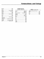
Chapter
1
Satellite
5003
5014
and
Setup
Receiver
Audio
(HD RCVRor AUX button)
Chapparal ..........................................
5056, 5057
Drake .................................................
5058, 5059
GE ......................................................
5000,5001
Generalln_uments
................ 5060, 5061, 5062
Panasonic ....................................................
5075
Prirnestar .....................................................
5076
(AUX button
only)
(For RCA and Dimensia brands only)
AM/FM .........................................................
Aux ..............................................................
Phono ..........................................................
CD ................................................................
4003
4004
4005
4007
Tape .............................................................
4006
PROSCAN ...........................................
5000,5001
RCA ....................................................
5000,5001
Realistic .......................................................
5063
Sony .............................................................
STSI .............................................................
5072
5064
STS2 .............................................................
STS3 .............................................................
STS4 .............................................................
Toshiba ........................................................
Toshiba ........................................................
5065
5066
5067
5068
5073
Uniden
5069
.........................................................
19
This page intentionally
left blank.
[_
HAPTER
The Menu System
Chapter
•
Overview:
Basic Operations
• The Picture Quality
• The Audio
Menu
Menu
• The Screen Menu
• The Function
• The Options
Menu
Menu
• The Setup Menu
• The Auto
Tuning Menu
• The Sleep Timer
2
The
Menu
System
Basic Operations
Power
To turn the monitor on and off:
1.
2.
3.
Plug the power cord into an active AC power outlet.
Press the ON-OFF button on the remote control or the monitor button on the unit. The
monitor's POWER/STANDBY indicator turns green when the monitor is on.
Press the ON-OFF
I,utton on the remote control or the unit to turn it off. The monitor's
POWER!STANDBY indicator turns red and the standby mode
unit with the remote control).
is set (only when turning off the
Volume
To adjust the volume:
1.
Press and hold the VOL > button (on the remote
level.
control or the unit) to increase to the desired
2.
Press and hold the VOL < button (on the remote
desired level.
control or the unit) to decrease
to the
Note: External speakers are required for sound.
Mute
Press the MUTE button on the remote control to reduce
the sound to an inaudible
level. Press
MUTE again to restore the sound.
Navigating
GUIDE
INFO
0
You
can
access
adjust
the
the Menus
monitor
main
meI_tl,
options
press
tl',rough
the
the
ivIENU
monitor's
button
menu
on the
or
remote
control
There
are a few things
you
need
to know
to navigate
through
the menu
system. The navigation
buttons
are the set of arrov¢-shaped
the middle of the remote (See illustration
on left).
/
buttons
in
CLEAR
These are the buttons on the remote
you use to navigate through the
monitor's on-screen menu system.
I rse the
and
•
and
•
buttons
()i_ the
remote
to move
the
menu
highlight
up
down.
Use the _
and
•
buttons
to nlove
Press lhe GO BACK button
YOLI
22
To
MENU,,OK on the front of tl_e monitor.
"_ZOOM"
MENU
systeln.
can return
the
luonitor
on the remote
to the
the RESET option
in the |:UNCTION
reset.
will return
AI.L settings
the highlight
facials.'
menu.
to the factory
and change
to return
settings
settings.
to a previous
al
any
Rememl_er,
lnentL
time by using
it you
choose
to
Chapter
6
settings.
The
Menu
System
The Multi-Screen Feature
The Muhi-Screen
same time.
feature is used to show either a single picture or two pictures on the screen at the
SINGLE - Displays a single picture on the screen.
SIDE BY SIDE - Displays two pictures from different
input signals side-by-side.
PICTURE IN PICTURE - Displays two pictures from different
one appears in a window on top of the other picture.
To use the Multi-Screen
input signals; one fills the screen and
feature:
1.
Press the WHOoMULTI button on the remote to select a mode.
2.
If side-by-side mode or picture-in-picture
mode has been selected, use the left/right arrow
buttons to position the subscreen as shown below.
Picture-in-Picture
Side-By-Side
qm
Side-by-side 1:
VIDE01 is the
[viDEo2]
active picture.
[V,DE02]
main screen
Side-by-side 2:
VIDEO1 is the
I VIDEO2 I
active picture.
[VIDEO2 ]
Picture-in-picture
(window on the left):
VIDEO1 is the active
picture.
Picture-in-picture
(window on the right):
VIDEO1 is the active
picture.
main screen
subscreen
m
,
The active picture (indicated in the ahove illustrations by the double box) is the picture that is
affected he remote actions and menu selections. To switch the active picture, press the OK
button. Press the OK button again to change back to the other picture.
Note: Changing the active picture doesn't change the size or location of the pictures.
Chapter
6
23
The
Menu
System
Selecting the Input Signals to be displayed
To change the input signals displayed
in muhiscreen
operations:
1.
2.
IVIDEO21
Press the MULTI button to activate the Multiscreen
OK button to make the desired picture active.
function. Press the
Press the RGB, VIDEO or CMPNT button to change tire input signal.
The INPUT-GO BACK button on the front of the monitor can also
be used to change input selection.
[VIDE01]
The top screen shows VIDEO1 as the
active picture. The bottom screen shows
VIDEO2 as the active picture.
On-Screen
Menu Operation
To access the main menu, press the MENU button on the remote. The MAIN MENU is displayed on
the screen. The main menu contains a list of all the menus that control your monitor. To select a
menu, use the up/down arrow buttons on the remote to highlight the desired menu. When the
desired menu is highlighted, press the OK or MENU button to select.
Note: Different components use different types of input (RGB, video, etc). 5ome menu
options apply to only one type of input, so they only appear when they apply to the currently
active input. For example, the COLOR and TINT options in the PICTURE QUALITY menu only
appear when you are adjusting standard video input (VIDE01, VIDE02, VIDE03).
24
Chapter
6
The
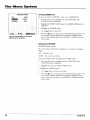
The Picture
Setting
Quality
the Picture
Mode
System
Menu
with
the
PRESETS Option
Tile monitor has preset viewing modes that can be selected
environment. Each preset mode has the contrast, brightness
viewing
Menu
depending on your viewing
and sharpness adjusted for a specific
sitkl:.ttlon.
bIEMOP,Y
This mode alk)ws you to set and save your own picture adjustments.
SOI_ - Use this mode when watching your Monitor in a dark room. Soft mode provkles a
darker, finer picture, like the screen in movie theaters. These settings are preset for you and
can't be changed.
•
BRIGHT - Use this mode when watching your monitor in a I)right room. This mode provides a
picture with distinct differences hetween light and dark areas. These settings are preset for you
and can't be changecl.
•
NORMAL - The factory clefault.
To change the picture mode:
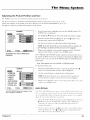
"
MAIN
MENU
AUDIO
1.
From the main menu, select PICTURE QUALITY. The PICTURE
QUALITY Menu will appear.
2.
Highlight the PRESETS option and press the • key on the remote to
select it. The PRESETS window appears.
3.
Use the • button on the remote to select the desired mode. The
mode switches as follows when the • button is pressed:
SCREEN
FUNCTION
OPTIONS
SETUP
AUTOTUNINGSETUP
€ SEL
I_r_
OK
r
i'd_
EXIT
MEMORY._-
SOFT _
Note: If you don't push the •
selection is set and the previous
BRIGHT
_
NORMAL_-j
button within 5 seconds, the current
screen reappears.
This is the main menu with the PICTURE
QUALITY option highlighted. Press OK to
bring up the highlighted menu.
Once you've selected
tile desired mode, press OK or MENU. Tile picture
[l!odc is no\v set :rod yot.i are returned
to tile PICTURE QUALITY screen.
If yon are using MEMORY mode, you can n/anually
adfust tile picture
settings (co[Itlasl. black level, and sharpness)
You can continue
adjusting
sellings ill I]/c PICI'ITRE QI ALITY menu, return to the main menu, or
c'xit
the
nlentl
system.
"1"oreturn to the main menu, press the GO BACK hutlon
To cxiI Ihc _ncnu s},slum, press CLEAIL
Chapter
6
on the rem<)te.
25
The
Menu
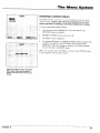
Adjusting
In MEMORY
CONTRAST
System
the Picture
Settings
lnod( _, _r()_ (.'all set and
- Changes
the picture's
BLACK LEVEL - Makes
the picture
SHARPNESS
the picture's
- Changes
COLOR - Changes
TINT - Changes
color
save the !_)llowing
contrast
lighter
(video
COLOR TEMP - Changes
the color
tone.
NOISE REDUCE
reduction)-
Only
the contrast
Once
you have
selected
Pi!
and
light and
dark).
mode,
only)•
only).
Removes
brightness
MEMORY
a(ljustments:
or darker.
input
input
- (noise
(between
picture
Mode
sharpness.
tint (video
NOTE:
picture
density
in MEMORY
extraneous
infk)rmation
can be adjusted
you
_ QUALITY
when
can adjust
1.
from the signal
a computer
the picture
signal
settings.
to make
For example,
to highlight
to change
or •
•
•
to select it. The CONTRAST
to adjust the contrast.
button
clearer.
is used.
Use the •
button
buttons
the picture
the contrast
the CONTRAST
window
option.
appears.
setting:
Press
Use
•
tile
and
NOTE: If you don't push the _ or • button within 5 seconds, the
current setting is accepted and the previous screen reappears.
This is the PICTURE QUALITY menu with the
PRESETS option highlighted,
2.
Once the contrast is adjusted, press OK or MENU. The contrast is set
and you are returned to the PICTURE QUALITY menu.
3.
Use tile same procedure
settings.
4.
When you are finished adjusting the picture settings, press GO BACK
to return to the main menu or press CLEAR to exit the menu system.
to adjust the black level and sharpness
If the "CONTROL NOT AVAILABLE"message appears when you are
trying to change the picture settings, make sure the preset mode is set to
MEMORY. You can only change picture settings in MEMORY mode. The
other modes are pre-set and can't be changed.
CONTRAST
__]0
This is the CONTRAST screen.
26
Chapter
6
The
Setting
Menu
System
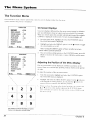
the Color Temperature
The (+t)lor tcmpezatute
',,ettmg
',van m t [ecl) or +.o( )] (blue))()ur
+,_ontt()l', ho'v,
picture L%The COLOR TFMP option ha s,4 .,ettmg,-.
Normal
\Varm
Pro (lets vou sele+.t -,etttngs m+.hv]duall,, )
Cool
COLOR
TEMP.
:4 PRO •
This is the COLOR TEMP screen w)th PRO as
the current selection
For legulat x levi rag, Not m.t[, \\.trm or O )ol _s re+.()n>mended The PRO
setung is generally+ used onl}+ ior professional apphcauons
To <+hat'tgethe
COlOR TEblP setting
1
From the FL+LJm
menu, l'nghhght and select the PICTURE QUALITY
menLl
WHITE
GAIN
Use the arrow butt(ms o[1 the remote to hlghhgt'_t the COLOR TEMP
opuon Press the • button to seie+.t tt The COLOR TEblP -.creen
appears
BALANCE
.
+
,L
-
iem
GREEN
BLUE
BIAS
RED
GREEN
BLUE
SEL.
3
0_10
: 7@_10
r+,+o,,.,,,
.-.
, o io
.. e lo
_
COLOR TEMP .,ettm R
.-+,o .-+oo,-q
/
L
- @ 1o
4)' ADJ.
Use the • and • bt]ttc)t't,_to -.elect the desned
The .,ettmg-; swttch +t'+iollov..,+,
NOTE: If you dot+'t push the • or • button _ ttb*n 5 seconds, the
current setting zs accepted and the pre_ *ous screen reappears
RETURN
This is the WHITE BALANCE screen with the
RED GAIN option h=ghhghted.
4 (.)nt_e the desue+.L<_ok)t te[l_p is '-,cle,_ted pres-, OK ot MENU If \'c,u
,+h¢)o'.e the PRO -,etttt'tg the \\ HITF BAL-\N(.F '<men appcdt +, It allox,..s
inch_ tdu.t[ .,citing
()P \_ hilt and d.tlk I'_aLmce t+.)1 e.t+.h +.o[ot _ted, green
and Illuc
GAIN
This .tdlusts the colol b.tlance for hgh[ bught colot'_
BIAS
This
the co'[lot bal.m+.e lot ddlk
adlu',P_
colols
T<)d_.mgc the ,,,.hlte I+.tlance G_IN setting
1
H[ghltght the RI:-D GRFF\ <)1BLLF G kin ()ptl<ln and pre-,-, the •
button Ih,+ (,kin ".tlecn h)t that +.ol+_t,tppca[-
2
-\tJIU'+,t
the Ixtlan+.e Ll'qng the • and • ke'+..
NOTE: It +,ou don't push the • or • button xxlthtn 5 seconds,
current setttn,g ,_ accepted and tim pre_ _ou. screen reappears
the
RED
3
\\ hen _<)u h.txc tile de.,ued sctttt't R p[c-.'. ()K (n J".II-NL_Ihe GMN ]_,
adlu+,ted
and
:<)u
AIL* [etutned
to ill,,- \\ HI It
i+ \[.-\NCF
sttecn
This asthe R-GAIN (red gain) screen
4
\\ h¢_'ll '_()LI L¢)nlpletL.d
6
the
de'qt,Jd
%%lit(++" i)LIL,LI_Lt.' ,tdlu+,tmetlt-_
"t2)tt(.an
v()ntllltl_
(_1 pie,',',
,Ivllkl_,[lll_,J.) plLttllu'
+.'L[ \R t() c\[t
Chapter
.ill
i've-,-, thc Go,) BA('Ix l)Llltt)n h) tLltltn it, tilt.+ I>IC'ILRF menu
thL_ ii/t.,nu
netlll+Lg +, IL)[LII[]
[(1 [hL
IILLIII1 nle[1tl
"-+\'-.iLl/1
27
The
Menu
Reducing
Noise
is a term
clearness
reception
System
Noise in the Picture
I.ise(I to describe
extraneous
bits oi lnfortl;atlon
In the signal
that aff.e,t the
of the picture
You can use tile Notse Reduction
(NOISE REDUCE) setting
is poor or when playing video tapes that ha;e poor picture quaht'.,'
d your
The NOISE REDUCE option has four setting,,, including OFF The higher the setting, the stronger
the effect The settings switch as follows ',',hen tile • button is pressed
[-_ OFF _
LOW *-_ MEDIUM "--_ HIGH "-]
To change the noise redrlCtlOn setting
From the PICTURE QUALITY menu, hlghhght the NOISE REDUCE
option, and select tt by pressing the • button The NOISE REDUCE
SCREEN _s dlsplaved
2
Use the • and • button.s to select the desired noise reducuon
_ettmg
NOTE: lf you don t push the • or • button within 5 seconda, the
clLrrent settlHg IS clcc_'pted and the prez lous sct ee_t l eappears
3
This is the PICTURE QUALITY menu with the
NOISE REDUCE (noise reduction) option
highlighted.
When the desired setting _s dtspla',ed press OK to return to the
PICTURE QUALITY meilu You can continue adlustmg picture
_ettmgb. rettnn 1o tile main menu, or press CLEAR to exit the menu
'_Y._tel/i
r
K
NOISE
REDUCE
T.
:4HIGH
k
This is the NOISE REDUCE (noise reduction)
screen.
28
Chapter
6
The
Menu
System
The Audio Menu
The AUDIO menu allows you to adlu_,t the treble, bass and left, nght balance
.,,peakm •
BASS - Change.', the level of low frequency
TREBLE - Changes
sound
the le',el of high frequency
BAL_.NCE - Changes
of ,,our external
sound
the balance of the left and nght speakers
Menu Operations
To access the AUDIO menu
1
From the mare menu, h_ghhght and select the AUDIO optzon
AUDIO menu ts displayed
2
Use the • and • arrow huttons on the remote to hzghhght an option
( tot example, BASS)
3
Use the • and I>"buttons to adlust to the des*red
-t
Yon can continue adlustmg audio settings, press GO BACK to return
to the mare menu, or press CLEAR to exit the menu system
The
semng
SEL
This is the AUDIO menu with the BASS option
highlighted. Press the right arrow button to
select it.
Chapter
6
29
The
Menu
System
The Screen Menu
The
the
SCREI-N
correct
positions
menu
allows
you
to set
th_
viewing a particular
of on-screen 111enLIs.
nlode
for
monitor
nlovit:
to aUtolnatically
to change
and
select
tht,
Selecting
a Viewing
When
with
viewing
Size
a cnnlponent
o/b_,r
tb_l/l.yollrHD/-t,
ceit%>r* you
can
set the screen nlode to one of |()LIr screen sizes to suit the type of input
you are watching. Select the screen mode with the CINEMA button on
the renlote control. The screen sizes are as Ik)llows:
FILLexpands in both vertical and horizontal directions while the correct
propol_ions are maintained. The picture is not distorted, just closer.
Fill
NORMAl displays a picture with a 4:3 aspect ratio (standard video).
Because this mode fills the screen vertically, but not horizontally, black
hars will appear on the right and left sides of the picture.
Note: If viewing with a 4:3 aspect ratio for Iong periods of time,
set side gray level at 3 or 4.
FUEt expands the picture in the horizontal direction only. This option
corrects the aspect ratio of images that have been compressed or
horizontally "'squeezed."
Normal
STADIUM expands in both the horizontal and vertical directions, but
varies the amount of stretch depending on the picture - the center of the
picture is almost normal while the edges are considerably expanded.
This mode is intended fk>rwatching video with a i:3 aspect ratio on a
wide screen.
Note: In Stadium mode, only the V-position and H-position
displayed. You can't change the height and width.
are
To change tile viewing size:
1
Full
Press
the CINEMA
button
on the remote
control.
The c'cuteilt viev, ing size ,.,,ill bc di_,pla}ed. Press the CINEMA hutton
:tgain to sv,itcl_ to tile, l]ex[
size
]'ILL
> Size
sx,,itches
+is
loll<>\vs:
FILL _
NORMAL
Note W/Je v e
g t, th c HD
_e/e_dous to set t/_e proper trzrio
_
FULL _
STADIUM
tlet,er, use t/_e rel¢il,er} _ ee ./!)rm, t
Stadium
30
Chapter
6
The
Adjusting
The
S('REEN
the
mcnu
Picture
lets you
Position
adjust
Menu
System
and Size
th_ + position
and
_izc
ot the picture
Tile first two options,
V POSITION and tt-POSI'I'ION,
adiust the placclnent
of the pRtule on the
screen. For example,
if the picture is too far to the left, you can use the tI POSITION to tt]{}x't+ it to
the right. To adjust the position
of the picture on the screen:
I.
SCREEN
From
NNORMALk
@ 10
V-POSITION
H-POSITION
@=3 ]Mm=lO
@:==3=mm!O
V-HEIGHT
H-WIDTH
tile
iTlain
menu,
highlight
and
select
tire SCI'_EEN
option.
Tile
SCREEN menu is displayed.
2.
Use the • and • butt,:)ns to select tile mode you want to change
3.
When the desired mode is highlighted, press tile • button. The
sdected mode screen ,,,,'illbe displayed.
Use the arrow buttons to adjust the position of tile picture.
NOTE:
current
SEL
4F ADJ.
_
RETURN
The SCREEN menu with the MODE option
highlighted,
4.
push
If you don't
setting
When
is accepted
you've
the an arrow
and
adjusted
button
the previous
to tile
desired
within
screen
setting,
seconds,
5
the
reappears.
press
tile
GO
BACK
button on the remote to return to the SCREEN memt.
The V-HEIGHT and H-WIDTH options expand and contract tile size of
tile picture to fill the screen. For example, if the picture is slightly wider
than the screen, you can use the H WIDTH option to shrink the picture
horizontally
Note: These options are not available
in STADIUM mode.
To adjust tile screen size:
SCREEN
1.
Select the desired option from tire screen menu and press the •
Imtt()n. The selected mode wit'_clow will be displayed.
2.
tJse the
:dFULL).
@ JO
@ =g::z:+mmmml©
V-POSITION
H-POSITION
V-HEIGHT
@ _"PmJ_+I
H-WIDTH
AUTO PICTURE
FINE
3.
NOTE:
[/)'olt
Cll/'rcql/
seltiu£
When
[etuin
PICTURE
PICTURE
€ SEL.
©
: OFF
arrow buttons
don't
cln (llron'
and
hutlou
tPithi/l
!l_(,prclious
5 S(?COlldS.
scrve/t
l]?g
reappea*_
t() tile desired setting, press OK t() select and
SCREEN
menu
ADJ.
4!_ ADJ.
[_
RETURN
The AUTO PICTURE option only appears if you
have a computer connected,
Auto
Picture
'[hc At'l{)
hdkL'
PIC[ fiRE funcli{>n
_1 COI11ptlR!l
('()nlR'LIL'C_
_dittsb
II/l_t!_C
10 aditlS[
1[ %(}kl \\;LI)[
So, loot
•
the
btltl{}l]
tumed{>lt,
clisplayc'd
2
Sc{ctt
AI rTO
:lppc:tl',
ill tIR'
IO IHL + I)_t)!/it{)l
{)11, tl ;ltlt(>lnatR:l]ly
1.
l]Rl\clilig
PICFUI'_E
alld
SC[{EI
the
I:lXl"
bencalh
an {}pll(}t/
N iIk=ntl
\_ IP21/ Ibis
silipcd
(}l/IV
R'a{tlrL
p:tttcu>
lI1:1
il x{Ytl
+ i_ tLIII]L'LI
c{>illputer
[[R'_,L + I/l_{l/kl_{ll\
(}piton
It@in the
SCi,_EEN
t(> ttulI/ :X[ "1'0 ]}[CI L'I{E _>11 \\'lien
\\ill he clispla,,ed
Pic'ss {)K It) icltili]
Chapter6
pnsD
i,_ ¢ICC_)te(I
aditlsted
yotfve
1o the
to adjust tile size of the picture.
PI(]IITRE
:lnd
PICI'[
:\(;'10
Rt" AI).l
nlcnu.
I'icss
the
I}ICTLTRI( Is
options
clio"
it
;lilt{
plL'S5
tilL'
•
/so" the • and
1o Ihc S(]I{I{E\
I}tl[t{)II
•
]hc
I}tltl<)l]s
ii/Clltl
street1
It) :{elitist
Iol that
that
{)pti{)n
{)plion
31
The
Menu
System
The Function
Ihe
FI]N(]TI()N
system)
and
Menu
menu
how
c(mtams
the
pictu(c
options
lhat
to]H[()l
_
:4ON,
MENU ADJUST
: 1
POWER
: OFF
SAVER
GRAY LEVEL
: 3
FILM MODE
: ON
RGB3 ADJ.
:
On-scrc_:n
give
Ih:m
the
menu
1
_
switch
than
about
inputs
) is displayed
tile
on
the
:in option
currently
the
To
From the main menu, highlight
and
The FUNCTION
menu is displayed.
2.
tlighlight
on-screen
3
: ot_
POWER
UST:
Olaf
GRAY LEVEL
3
FILM MODE
ON
RGB3 ADJ.
1
Adjusting
the
,_
RETURN
\
/
\
/
\
/
\
/
\
/
2
7
................
the
Use the •
option.
b'0tton
to toggle
off does not affec! on-screen
the Position
of the Menu Display
position of the
on-screen
lltellUS:
2.
l lighlight and select the MFNU AI)JUST option. Use the • button (o
Scloll through
the n'_enu l)ositi(ms As you press the • I)utton, the
menu _\ilt _u_\e tuotu_,.I to Ihe dit{k:rcnt p<)sitiol'_s
When
" 3
5
,,
the FUNCTION
off:
From the mare ntenu, highlight and select the FUNCTION option.
Tile FUNC'I'ION menu is displayed.
\(Itl
i_lc_,s (;1)
[ht'
. .............
example,
I
/
\
•
select
(lor
displays
right.
To atl}tlSt
_1_ADJ,
4
n:.uue
_t)
example,
The on-screen menus can de displayed in diff'eren_ positions on the
screen. There are a total of nine possible positions shown in the grid on
SAVER
1
input
turn on-screen
and select the DISPLAY option.
disp]tlys on or off.
by de,huh
For
You can contin0e setting options in the FUNCTION menu, press GO
BACK to return to the main menu. (>rpress CLEAR to exit the menu
system.
RESET
# SEL
appea_
selected.
:42,
SAVER
SCREEN
systmn)
have
RETURN
FUNCTION
O)SPLAYI
you
selected
screen.
Nole: Turning the DISPLAY option
menus. Menus can't be turned off,
;M,EN_LI
menu
1
SAVER
4_ ADJ.
(di{ferent
intorlnation
you
CMPNTI
Displays
dispkws
you
When
RESET
SEL.
(o[hel
displays
On-Screen
FUNCTION
SCREEN
Oll-S_IVL'n
is displayed¸
hiD. e tl_., ltlCI1ll
B.\(IK
h_ ictu_n
ill the
desired
t_ tile' ill,till
l)()siti_)n
n_nu,
)ou
ol prc>s
can
prt*ss
(:LEAR
Its<,
t<> t'xit
ii]L,l_tl _%_l_,tl]
6
t
- ................
8)9
The number
2 position
will display
on-screen
menus in the top center
of your screen.
32
Chapter
6
The
FUNCTION
DISPLAY
: ON
MENU ADJUST
:
Setting
;go'Wt_g'_X_Lql:4ON•
: 3
FILM MODE
: ON
RGB3 ADJ.
: 1
SCREEN
This
SAVER for Computer
Images
atitomatica]ly
l+Mdl.l_._s
the'
monitor's
pox_er
tk)r a certain anlount
it
c()tl_tlmpti(>[1
of time. POWER SAVER
If tile computer's
power isn't turned on or if the comptlter
and selector
tuner are not properly
connected,
POWE.R SAVER is set to OFF.
SAVER
4• ADJ.
ftlilCtioi_
no operation is performed
can be turned on o1 <)if.
RESET
SEL
POWER
System
Ill,_" P()x.X;ER&,\VER function can be ns_.:d when th,::signal _,our_c to the
monitor comus from a computer
confolnling to I]lU VE_A I)]>MS [orln;i[
1
GRAY LEVEL
the
Menu
['ffiI_W_RETURN
This is the FUNCTION menu with
SAVER option highlighted,
the POWER
For
instnlctions
see
your
"Eo turn
on
using
computer's
tile
the
colnpnter's
operating
monitor's
power
nlanagement
fllnCtio[i,
manual.
POWER
SAVER
function
on
or off:
1
From the main mentl, highlight and select FUNCTION. The
FUNCTION menu is displayed.
2.
flighlight
3
Use the I_ button to toggle the setting ON or OFF.
4.
Yotl can continue making adjustments in the FUNCTION menu,
return to the previous menu by pressing the GO BACK button or
press CLEAR to exit the menu system.
the POWER SAVER option.
The POWER, STANDBY indicator shows the statl.is of the PO\VER SAVER
function. Sec below fk)r status and description.
POWER/STANDBY indicator
POWER
SAVER
Mode
POWER,
S'IANDBY
indicator
On
Gret'il
Pox_
er
Saver
Operating
l)escription
Status
Not activatc]d
Horizontal
Turning the Picture Back On
Picture aheadv on
and \ertica]
synchronizing signals :ire
prcserlt
:\c Ii_ :iicct
5t:ulclbv
I>cd
stl_pcl/d
\c lit :tic'el
Nt)
fri)lll
[hu
hoHzotlhll
>l_ll_tlS
:IFC
c.t Illlpt
IIUI"
COl/lptlfef
I ',c the kc}boctld ol nlousc
s}ilchrt)[/izillg
t)IttSt'l/[
lhc piCtUlC rc:lplbcais iunnudi:tlcl).
11"O111 !lit'
No _ crlk ;il s} [/chn)nizin_d >lgl/:llS
I >c tilt'
;tic
plClUlC
plCSClll
l/(l!ll
{hc
( Oll/l)Ult
I
lh:lll
Oil
Red
\tti_
:ilccl
\t!
>}lit
lit)liZOlll:il
hlolii/ii/_a
[1{)ii1 Iht'
:lI/d
_ t'llic:ll
-ign;ils
cclllll3tl(t'I
ale
!'_t
file
6
Ill
Iv>_li_[_c>:ilS i_ul
\\ht'n
ill
kt'\lxl;tltt
>Ltndl_\
Illtltlst'
lll_)['t'
Ihc
_l_l\"
ll!_lc
*111Illl>tl>c'
"t hc
{xc.cnl
Ill:in
tXllc'l/
-tl_pCllcl
Chapter
kcdx>:nd
in c'ili/c'l ¸ _l:uldb\
t_f
1/1( )dr'
33
The
Menu
System
FUNCTION
Setting the Gray Level for the Sides of the Screen
DISPLAY
: ON
The
MENU ADJUST
: 1
POWER
: OFF
Ihe screen where nothing is displayed (on Ih(" h'h and righl sides of tilt"
screen when it is set to 4:3 size). The ]excl can lie adjusted from 0 to 1"3.
Tim factoi T setting is 3 (clark gray).
SAVER
FILM MODE
:ON
RGB ADJ.
:1
4k ADJ.
_
RETURN
LEVEL option highlighted,
NOTE: Repeated watching with the
gray level set to black may effect the
alh)',vs
_r()_ t( ) S_'[ the
gray
level
for the >,ides {if
1.
From tile main menu, highlight and select FUNCTION. The
FUNCTION menu is displayed.
2.
l lighlight the GP,AY LEVEL option.
3.
Use the • button to scroll through
,t.
When tile desired gray level is highlighted, i)ress the • button to
return to tile FUNCTION menu r)ptions You can continue making
a(ljustments within the FUNCTION menu, press GO BACK to ]cturn to
the previous menu or press CLEAR to exit tile nlgnLi system.
quality of your picture. To reduce the
effects of uneven phosphor aging, set
the gray level to 3 or 4.
with
lunction
To adjust file gray level for tile sides of tile screen:
This is the FUNCTION menu with the GRAY
If viewing
LIqVI'I.
/VOTE: Repeated watching with the gray level set to black may effect
the quality of your picture. To reduce the effects of uneven phosphor
aging, set the gray level to 3 or 4.
SCREEN SAVER
RESET
SEL.
GRAY
a 4:3 aspect
for long periods
of time,
gray level at 3 or 4.
set
ratio
side
Adjusting
for Flickering
with
is some
anlotlFlt
of flickering
trans[_erred from film to video
There
ON All images are displayed
the levels.
that
Film Mode
OCC'LIFS if] :In
ill]age
v/heFt
it is
in film mode
OFF FHm mocle is off.
To turn FILM MODE ON:
FUNCTION
DISPLAY
1,
From the main menu, highlight and select FUNCTION. The
FUNCTION menu is displayed.
2.
Highlight tile FILNI MODE option
3
Use tile •
displa3 ed
: ON
MENU ADJUST : 1
POWERSAVER : OFF
GRAYLEVEL
: 3
:4ONi_
RGB3ADJ.
: 1
SCREEN SAVER
RESET
Press
41_ADJ.
_
•
c_ua c{}ntmue
t(} the
the
€ SEL.
tile
button
to scroll
I+uth}n
I{} tt'tUltl
nlaking
l'>re_ i(}cis niL'nil
inc, nu
through
:tcIiuslnR,
by
t{> the'
tile" thlee
FI+NCIION
n(s \', ithin
ple>sillg
G()
moclcs
menu
until ON is
(}ph(ms
tilt., F[ N{.7I'ION
I}ACK
{}i press
You
menu.
CI.t{AR
R, turn
[{} exit
system
RETURN
This is the FUNCTION menu with the FILM
MODE option highlighted.
34
Chapter
6
The
FUNCTION
Adjusting
DISPLAY
: ON
MENU ADJUST
: 1
POWER
: OFF
SAVER
GRAY LEVEL
[l the picture
1
From
is not
the + tll_iin
menu
: : ON
:411_
sCREEN
the Monitor
stable
it+ I/(;B3
mt, ntl,
highlight
System
in RGB3 Input
Mode
inoclc.,
AI)IUST
use tilt'
R(;I+]
ftJantrt +
to acljust it.
: 3
FILM MODE
Menu
select OPTIONS+ The OPTIONS
and
is displayed.
2.
Highlight tile RGB3 ADJUST option.
3.
Use the • bum)n to select tile desired
choices scroll as follows:
SAVER
RESET
SEL
<lb ADJ.
_
adjusmmnt (1, 2 or 3). The
RETURN
1
This is the FUNCTION menu with the RGB3
2
3 -j
ADJ. option highlighted.
,i.
When the desired number is selected, press the • button to return to
the FUNCTION menu items. You can continue making adjustments
within the FUNCTION menu, press GO BACK to return to the
previous menu or press MENU or CLEAR to exit the menu system
Note: When AUTO PICTURE is on, switch it off and back on again
to return the display position to its original position.
Setting the SCREEN SAVER
FUNCTI
DISPLAY
MENU
The SCREEN SAVER option contains three features in one. These features
are cised principally for PC operation.
: ON
ADJUST
POWER
ON
SAVER
: 1
: OFF
GRAY LEVEL
: 3
FILM MODE
: ON
RGB3 ADJ.
:
The ORBITER (Peak Luminance Enhancement) moves the image around
tl_e screen intermittently to reduce the effects of phosphor aging.
1
The INVERSE function works in RGB mode only. INVERSE inverts the
video signal, playing tile image in a negative format.
RESET
SEL.
The PLE (Peak Luminance Enhancement) function sets the luminance
level to a fixed mode t() rednce the eft:eels of phosphor aging.
4_ ADJ.
['_]'_IRETURN
Setting
This is the FUNCTION menu with the SCREEN
SAVER option highlighted.
the PLE
PI.E has two options:
,-\[;TO
lciminance
level
(£Olltlas[)
is nornla]
I.OCK
dims pk'tlirc to rednce pi/osphor agulg
t'a(.'tOl T setting is AI TO Setting
1)ictcirc - die contiast
x\ilI be lo\_cr
"Ihe
Setting
PLE to LOCK is
recommended if you are displaying
stationary
pictures.
Frolll
tilt"
inclin
Iliglllighl
tilt'tiLl,
inenn
FUNCTION
tlighlight the, I)I.E option
3
[ !Se
i
Press
tile
•
tile
button
•
ICq!lln
Int'I1ll
select
FIINCIION
'ihc
select I.O('K
to
I)tltton
1(> tilt. >
:lnd
iS displayed
2
Ceil] contillue
6
noliital
I'<>set the' PI.E Ic_cl t<) I.OCF.:
1
Chapter
the PLE option to LOCK dims tilL'
titan
to
making
prcvi(_ns
ictnl0
to
adjustnlcnts
InL'Iltl
Ol
the
FI:Nt]TI()IN
x\ithm
the
pi'c'ss MEN(
illeiltl
optiolls
F/:NOTION
or CI.EAR
"lou
mc't]tl.
to
CXil
Iltc"
5\ Slel//
35
The
Menu
System
SCREEN SAVER
PLE
INVERSE
SEL.
Turning ORBITER on
: AUTO
The factory setting for ORBITER is OFF. To turn ORBITER ON:
:4ONk
1.
From the main menu, highlight and select FUNCTION. The
FUNCTION menu is displayed.
2.
Highlight the SCREEN SAVER option (the SCREEN SAVER menu is
displayed).
3.
Highlight the ORBITER option.
4.
Use the • button to select ON.
5.
Press the • button to return to the FUNCTION menu options. You
can continue making adjustments within the FUNCTION menu,
return to the previous menu or press MENU or CLEAR to exit the
menu system.
OFF
-4> ADJ.
r_l_FJ RETURN
This is the SCREEN SAVER menu with the
ORBITER option highlighted.
Setting
the INVERSE
hNVERSE has three options:
ON - The picture is ahematively
image.
displayed
as a positive and negative
OFF - INWERSE is off.
WHITE - The screen turns white.
The factory setting is OFF. To change
the INVERSE mode:
1.
From the main menu, highlight and select FUNCTION. The
FUNCTION menu is displayed.
2.
Highlight and select the SCREEN SAVER option.
3. Highlight the INVERSE option.
36
4.
Use the • button to select your choice.
5.
Press the • button to return to the FUNCTION menu options. You
can continue making adiustments within the FUNCTION menu,
return to the previous menu or press MENU or CLEAR to exit the
menu system.
Chapter
6
The
RESET
RETURN
Resetting to Default
Menu
System
Values
The RESET functkm allows you to reset_ adiustmems to th_ factory
default settings. Caution:
this will reset all adjustments
you have
made
in all menus,
To reset
to the factory
including
dethult
autotuning
configuration
settings.
settings:
1.
From the main menu, highlight
FUNCTION
menu is displayed.
2.
Highlight
3.
The RESET screen
4.
[Jse the • or • button to highlight
the RESET option and press OK
or MENU. The RESET screen will display the message
NOW
RESETTING. When the settings are restored
to the factory default
you are returned
to the RESET screen.
the RESET function
and
select
and press
EUNCTION.
The
OK.
is displayed.
When you are done, press GO BACK to return
or pres CLEAR to exit the menu system.
to the FUNCTION
menu
These are the RESET screens. Choose the
RESEToption if you want to reset ALL
options in a_ menus back to the factory
default.
Chapter
6
37
The
Menu
System
The Options menu
Setting the Audio Inputs
The monitor's audio sources are programmable
to the each of the monitor's video sources.
example, you can program AUDIO1 source to work with the RGB2 video source.
This feature
is generally used only for commercial
applications.
1.
From the main menu, highlight and select OPTIONS. The OPTIONS
menu is displayed.
2.
Highlight the one of the audio input options.
3.
Use the • button to scroll through
modes scroll as follows:
FVIDEO1
4.
This is the OPTIONS menu with the AUDIO/
input option highlighted.
For
_VIDEO2
_
VIDEO3
_
the available video sources. The
CMPNT1
_
RGB1 _
ROB2 _
RGB3
When the desired mode is selected, press the • button to return to
the OPTIONS menu items. You can continue making adjustments
within the OPTION menu, press GO BACK to return to the previous
menu or press MENU or CLEAR to exit the menu system.
The factory defaults are as [bllows:
• AUDIO1 - VIDEO1
• AUDIO 2- CMPNT1
• AUDIO3-
RGB1
If you use the reset option in the FUNCTION menu,
return to the factory default settings listed above.
Setting
HD SELECT
PICTURE SIZE
# SEL
_
RETURN
This is the OPTIONS menu with the BNC
SELECT option highlighted.
38
will
the BNC Connectors
If tile component you are connecting to the monitor doesn't have
composite video jacks, you can set the BNC inputs to act as component
video inputs.
: 1080A
: ON
_1_ADJ.
the settings
1.
From the main menu. highlight and select OPTIONS. The OPTIONS
menu is displayed.
2.
Highlight the BNC SELECT option.
3.
Use the • button to toggle between
CMPNT2. (component).
4.
Once you've selected the desired setting, press the • button to
return to the OPTIONS menu items or press CLEAR to return to the
main menu.
RGB2 (composite)
and
Chapter
6
The
Setting a Computer
Select Mode
Tile RGB SELECT function
ik)r the type of con_puter
Image
alk)ws
image
to the Correct
you to select
the correct
Menu
System
RGB
viewing
mode
you are displaying
The RGB SELECT function has six modes:
AUTO - Automatically
input signal.
selects the most suitable
STILL Use this mode to display VESA standard
computer).
mode fk_rdisplaying
tile
signals (still image from a
MOTION - Use this mode for moving images from a computer.
the signal to RGB signal for best viewing.
Converts
WIDE1- Prevents horizontal compression when the input signal is 852 dot
X 480 line signal with a horizontal frequency of 31.7kHz.
WIDE2 - Prevents horizontal compression when the input signal is 848
dot X 480 line signal with a horizontal frequency of 31.0kHz.
I)TV - This mode is primarily used to optimize picture quality if you are
using a generic brand I)TV receiver which outputs signal at 4g0P
(progressive scan) lines.
To change the RGB SELECT mode:
OPTIONS
1.
AUDIO INPUT
AUDIO1
AUDIO2
AUDIO3
BNC SELECT
HD SELECT
: VIDEO1
:" CMPNT1
: RGB1
: RGB2
:4AUTOI_
: 1080A
PICTURE SIZE
: ON
SEL.
4_ ADJ.
3.
Highlight the RGB SELECT optkm.
Use the • button to scroll through
switch as follows:
the mode choices. The settings
_-_AUTO _" STILL _- MOTION "--_WIDEI"_"
WIDE2 -_ DTV
r_I_RETURN
This is the OPTIONS menu with the RGB
SELECT option highlighted.
2.
From the main menu, highlight and select the OPTIONS menu. The
OPTIONS menu is displayed.
When the desired mode is selected,
press the ._ button to return
the OPTIONS
menu items. You can continue
making adjustments
wiflfin the OPTIONS menu. press GO BACK to return
menu or press ('.LEAI_. to exit the menu system
Chapter
6
to
to the previous
39
The
Menu
System
Setting the Monitor
to the correct HD Receiver Mode
The HD SELECT _nction allows y_m to select tt_e correct mode _)r the monitor to work with your
HI) receiver. The default setting is 1080A. This is the correct setting 12)rall RCA and PROSCAN HD
receivers. If you have another brand of HD receiver, your picture may appear broken or off-center.
If so, you need to switch HD SELECT modes.
1080A - Use this option for RCA or PROSCAN HD receivers.
1080B - Use this option if you have any other brand of HD receiver.
To change the receiver
1.
mode:
From the main menu, highlight
and select OPTIONS. The OPTIONS menu is displayed.
2,
Highlight
3.
Use the II_button to select the desired mode (1080 A or 1080 B).
4.
When the desired number is selected, press the _ button to return to
the OPTIONS menu items. You can continue making adjustments
within the OPTIONS menu, press GO BACK to return to the previous
menu or press MENU or CLEAR to exit the menu system.
Setting
This is the OPTIONS menu with the HD
SELECToption highlighted.
the HD SELECT option.
the Picture
Size for RGB Input
The PICTURE SIZE option is used to adjust the picture size when the
input signal is RGB. Use this feature for graphic arts and checking
photos. In TRUE mode, there is no distortion of the picture. In NORMAL
mode, the picture will be scaled vertically but will keep the correct
aspect ratio.
ON - When the picture size option is on and in NORMAL mode, the
picture is scaled to fill the screen vertically while horizontally keeping the
correct aspect ratio. In FULL mode, the horizontal will be scaled to fit the
screen.
BNC SELECT
RGB2
RGB SELECT
: RGB
HD SELECT
: lO_A
_"g_t_,_l
€ SEL.
<> ADJ.
-
:_ON,
[_r_i_RETURN
OFF - When the picture size option is off, TRUE mode displays the
picture pixel-R)>pixel, exactly the size of the image. If FULL mode, the
image is scaled to fit the screen.
Note: When using a DTCIO0 HD receiver, the only available mode is
FULL. The picture will be scaled to fill the screen,
This is the OPTIONS menu with the PICTURE
SIZE option highlighted.
40
Chapter
6
The
Menu
System
The Setup Menu
The
SETUP
nlenl.i
controls
the
way
your
monitor
communicates.
Confirming the Frequencies, Polarities, Mode and Resolution of
Input Signals
The FREQUENCY function is used to confirm the frequencies,
the signals coming from a computer.
To confirm frequencies,
polarities,
polarities, mode and resolution
of
mode and resolution:
1.
From the main menu, highlight
SETUP menu is displayed.
and select the SETUP option. The
2.
Highlight the FREQUENCY option and press OK.
3.
The FREQUENCY screen is displayed.
Press GO BACK to return to the SETUP menu, or press CLEAR to exit
the menu system.
This is the SETUP menu with the FREQUENCY
option highlighted.
H. POLARITY
: NEG.
V= POLARITY
: NEG.
MODE
:
8
RESOLUTION
:
640 X 480
r'_J_l RETURN
This is the FREQUENCY screen.
Chapter
6
41
The
Menu
Selecting
System
the Language
for the Menus
The menu display can he set to one of three languages:
English. To change the delimit setting:
MENU LANGUAGE
English, French or Spanish. The detkmlt is
1.
From the main menu, highlight and select the SETUP option. The
SETUP menu is displayed.
2.
Highlight the MENU LANGUAGE option. The MENU LANGUAGE
screen is displayed.
3.
Use the • button to scroll through
settings switch as follows:
F .(;AIS
4.
This is the MENU LANGUAGE screen with
Spanish as the selected language.
the language choices. The
ESPA OL
When the desired language is highlighted, press GO BACK to return
to the SETUP menu. You can continue making adjustments within
the SETUP menu, press GO BACK to return to the main menu, or
press CLEAR to exit the menu system.
Setting
the Video
Signal
Format
The COLOR SYSTEM option is used to set the video signal format.
Different countries used different formats l;:)r video signals. The AUTO
option automatically detects the correct video signal and sets the correct
format. This setting should not be changed.
42
Chapter
6
The
The Autotuning
Autotuning
Menu
System
Menu
the Component
buttons
on the Remote
Control
The AUTOTUNING feature lets you easily program the component buttons on the remote to operate
the components hooked up to the monitor. 12) autotune your components to the buttons on the
remote:
From the main menu. highlight and select the AUTOTUNING SETUP
option. The AUTOTUNING SETUP menu is displayed.
1.
2.
.
4,
This is the AUTOTUNING
SETUP menu with
the DVD BUTTON option highlighted.
Chapter
6
Highlight an option which corresponds
to a component
which
you've connected.
For example,
if you have a DVD player
connected,
highlight
the DVD BUTTON option.
Use the _. button to scroll tl_rough the output choices. Select the
choice which corresponds to the jacks you used to connect the DVD
player. In the example illustration on the right, the DVD button on
the remote will operate the component connected to the CMPNT1
jacks (the DVD player).
When the desired option is displayed, press the • button to return
to the AUTOTUNING menu options. You can continue making
adjustments within the OPTIONS menu, press GO BACK to return to
the previous menu or press CLEAR to exit the menu system.
43
The
Menu
System
Sleep Timer
The sleep timer is a feature that allows yoll to set tile monitor to turn off after a prescribed
of time. It can be set to turn tile power off after 30, 60, 90 or 120 minutes.
amount
Setting the Sleep Timer
1. Press the SLEEP button on the remote
to turn on the timer. Tile default is 30 minutes.
2. Press tile SLEEP button again to move to the next time increment.
until you get to the desired time.
_30_
Press the SLEEP button
60_90_120-_0_
3.The timer starts when the Sleep display disappears
To check the Remaining
from the screen.
Time:
1. Once the sleep timer has been set and tile menu has turned off, press the SLEEP button
once.
2. The remaining
time is displayed,
then disappears
3. When five minutes remain, the remaining
Cancelling
after a few seconds.
time appears
until it reaches
zero.
the Sleep Timer
1. Press the SLEEP button twice in a row.
2. The sleep timer is canceled.
NOTE: After the power is turned off"with the sleep timer, a slight current is still supplied
to the monitor. If you do not plan to use the system for a long period of time, turn the
power off with the remote or on the unit.
44
Chapter6
R
HAPTER
Other Information
Chapter
Overview:
• Installation
•
Connecting
Computer
Your PC or Macintosh
• Specifications
• Troubleshooting
• The Menu System
• Supported
•
Limited
Resolution
Warranty
• Accessory
Information
3
Other
Information
Installing
the Cinema
Screen
Monitor
IMPORTANT
• This device cannot
•
For correct
dealer.
stand on its own. Be sure to use a stand or original
installation
Failure to follow correct
Product
Attaching
and mounting
mounting
it is strongly recommended
procedures
warranty does not cover damage
optional
mounts
or stand
mounting
unit.
to use a trained, authorized
could result in damage to the equipment
caused by improper
to the Cinema
Cinema Screen
or injury to the installer.
installation.
Screen
monitor
The Cinema Screen monitor can be mounted on tile wall using an optional wall mount or you can attach a floor stand (also
optional). For more information on mounting your Cinema Screen Display, see your Cinema Screen dealer.
If you choose to use the optional wall mount, it can be attached
ways:
•
•
to the Cinema Screen monitor
in one of the l_)llowing two
While it is upright.
While it is laying with the screen face down. If you choose this option, lay the protective
around the monitor beneath the screen surface so it doesn't get scratched.
Ventilation
requirements
To allow heat to disperse,
for
enclosure
leave space between
sheet that came wrapped
mounting
surrounding
objects as shown on the diagram helow when installing.
--.-
I
50mm (2")--*
i 50mm(2", 1
1"--
1240mm (48.8")
,
E
E
'/
t
50mm
(2")
E
E
0
L¢3
46
Chapter
7
Other
Connecting
Computer
Your PC Or Macintosh
Mini
Information
D-sub 15 Pin VGA Signal
Composition
Connecting your PC or Macintosh computer to your
Cinema Screen monitor will enable you to display
computer images on the monitor. The Cinema Screen
monitor supports the signals descrihed on page 48.
To connect
adapter:
1.
to a PC, Macintosh
or compatible
graphics
Turn off the power to your monitor and computer.
2. If your PC does not support XGA/SVGA/VGA you will
need to install an XGA!SVGA/VGA graphics board.
Consult your computer's owner's manual for your SXGA/
XGA! SVGA/VGA configuration. If you need to install a
new board, see the manual that comes with your new
graphics board for installation instructions.
3. The Cinema Screen monitor provides signal
compatibility with VESA 128021024@60MHz (SXGA).
However, we recommend not using this resolution due to
image readability on the monitor's 853 X 480 native pixel
resolution panel.
4. Use the signal cable that's supplied to connect your
PC or Macintosh computer to the Cinema Screen monitor.
For Macintosh. you will need a monitor adapter (not
supplied) to connect to your computer's video port.
5.
Turn on the monitor and the computer.
6. If the Cinema Screen monitor goes blank after a
period of inactivity, it may be caused by a screen saver
installed on the computer you've connected to the
monitor.
When using a Macintosh with the Cinema Scteen
monitor, tile following three display standards arc
supported using tile included Macintosh adapter : 13" fixed
mode, 16" fixed mode. and 19" fixed nlode. The 13" fixed
mode
is recommended
for the Cinenla Screen 111onitor.
Chapter
7
Pin No.
Signal
to be connected
1
RED
2
GREEN
3
BLUE
4
No connection
5
GND
6
RED
7
GREEN
8
BLUE
9
No connection
10
SYNC
11
No connection
12
SDA
13
H. Sync
14
V. sync
15
SCL
or sync.
on Green
(GND)
(GND)
(GND)
(GND)
47
Other
Information
Specifications
I 89"
ProductName
PHD50300
CinemaScreenMonitor
ScreenSize
43.5"(H)X 24.5"(V)inches
1106(H)X 622(V)mm
AspectRatio
Resolution
ColorReproduction
Input Signals
RGBinput terminals
RGB1
RGB2
RGB3
VideoInputterminals
Video1
Video2
Video3
DVD/HD/DTV
Audio
ExternalControl
SoundOutput
PowerSupply
CurrentRating
PowerConsumptiOn
Dimensions(WxDxD)
.....
"""'-'........
_
H-t231"
435"
diagonal
50"
16:9
1365(H)X 768(V)pixels
256levels,16,770,000colors
RGB,NTSC(3.584.43),PAL(B,G,M, N),
PAL60,SECAM,
HD.1, DVD.1, DTV*
l
mini D-sub 15-pin
BNC(R, G, B, H/CS,V) Xl
DVt-I2g-pinX 1"2
Thefeaturesand specificationsmaybesubjectto change
withoutnotice.
RCA-pinX 1
BNCX 1
S-Video:DIN4-pinX 1
RCA-pin(Y,P,[C=!,P,[C,])
StereoRCAX 3
D-sub9-pinX1(RS-232C).
7W+7Wat6 ohm
AC120V50/60Hz
* HD/DVD/DTV
inputsignalssupportedon this system
480P (60
525P (60
625P (60
720P (60
Hz)
Hz)
Hz)
Hz)
4801 (60 Hz)
5251 (60 Hz)
6251 (60 Hz)
7201(60 Hz)
10801(60 Hz)
5.9A(maximum)
595W(typical)
1240X 766X 107ram(w/ostand)
48.8X 30.2X 4.2inches(w/ostand)
1240X 826X 400ram(with stand)
NetWeight
Environmental
Considerations
Operatingtemperature
Humidity
Altitude
Storagetemperature
Humidity
FrontPanelUserControls
46 Kg/101.3Ibs.(w/ostand)
O°Cto 35°C/32°Fto 95°F
20 to 80%
0 to 1900m/0 to 6239 ft.
-10°C to 5g°c/14°F to 122°F
10to90%
Poweron/oft, Input source select
Volume up/down/OSDcontrol
OtherFeatures
Power Management, plug and play (DDCl,
DDC2b, RGB3: ODC2bonly)
Accessories
Remote control with two AA batteries, RGB
cable (Mini D-sub 15 pin to Mini D-sub 15-pin
connector), power cord, safety metal fitting,
strew for safety metal fitting, User's Manual
Regulations
ULapproved (UL 1950, CSA950)
DOCCanadarequirements
Meets FCCclass B requirementsfor home
application
48
Chapter
7
Other
Information
Troubleshooting
Before requesting
service, check the adjustments,
operations,
etc.
Symptom
Possible Problem
Solutions
Pictureis disturbed.
Soundis noisy,
Remotecontrolunit operateserroneously.
• Is a connectedcomponentsetdirectlyin front
or at the sideof themonitor?
• Leavesomespacebetweenthedisplayand
connectedcomponents.
Theremotecontroldoesnotwork.
• Remotecontrolbatteriesmaybe dead.
• Remotemay bein wrongmode.
• Replacebothbatterieswith newones.
• Presscomponentbuttonfor desiredcomponent.
Monitor'spowerdoesnotturn on whenthe
remotecontrol'spowerbutton is pressed,
• Is the monitor'spowercordpluggedintoa
poweroutlet?
• Plugthe monitor'spowercord intoa power
outlet.
• Are all the monitor'sindicators
off?
• Pressthepowerbuttonon the monitorto turn
on the power.
Monitordoesnot operatewhentheremote
control'sbuttonsare pressed.
Nosoundor pictureis produced.
; • Is the remotecontrol pointedat themonitor,
or is therean obstaclebetweenthe remote
controlandthe monitor?
• Pointthe remotecontrolat the monitor's
remotecontrol sensorwhenpressingbuttons,
or removethe obstacle.
• Is direct sunlight or strong artificial light
shining on the monitor's remote control
sensor?
• Eliminate the light by closing curtains, pointing
the light in a different direction, etc.
• Remote control batteries may be dead.
• Replacebothbatterieswith newones.
• Is the monitor'spowercordpluggedintoa
poweroutlet?
• Plugthe monitor'spowercord intoa power
outlet.
I
• Is the sourcevideoconnectedandon?
• Makesuresourcevideo(VCR,DVD,DTC)is
connectedandturnedon.
• Is thevolumeset at theminimum?
• increasethevolume.
• Is the mutemodeset?
• Pressthe remotecontrol'smutebutton.
• Arethe speakersproperlyconnected?
• Connectthe speakerspropedy.
Tintis pooror colors areweak.
• Arethe tint andcolors properlyadjusted?
• Adjustthetint and color(underPICTURE).
• Returnto factoryreset.
Nothingappearson screen.
• ts the computer's power turned on?
• Turnon thecomputer'spower.
• Is a video source connected?
• Connectvideosourceto the monitor.
,_Is the power manager function in the
STANDBYor OFFmode?
• Operatethe computer(movethemouse,etc.).
Part of picture is cut off or picture is
not centered.
• Is the picture position adjusted correctly?
• Adjust the picture from the SCREENmenu.
Image is too large or too small.
• Is the screensize adjustedcorrectly?
• Pressthe WIDE/AUTOWIDE button on the
remote control and adjust properly.
Picture is unstable.
• Is the computer set at the correct resolution?
• Set to the proper resolution.
Picture appears but no sound is produced.
I " Is the HD receiverset to the correct mode?
Chapter
7
• Set HD receiver to the correct mode (page 29).
49
Other
Information
The Monitor
Menu System
Main menu
Sub menu
Functions
PICTURE QUALITY
CONTRAST
Adjusts the contrast.
BLACK LEVEL
Adiusts the brightness.
SHARPNESS
Adjusts the sharpness.
COLOR
Adjusts the color density (video input only).
TINT
Adjusts the picture tint (video input only).
PRESETS
Sets the picture mode according
COLOR TEMP.
Adjusts the color temperature
NOISE REDUCE
Reduces noise visible in image,
Main menu
Sub menu
Functions
AUDIO
BASS
Sets the bass.
TREBLE
Sets the treble.
BALANCE
Sets the left/right
Main menu
Sub menu
Functions
SCREEN
V-POSmON
Adjusts the vertical
H-POSITION
Adjusts the horizontal
V-HEIGHT
Adjusts the vertical size of the picure.
H-WIDTH
Adjusts the horizontal
AUTO PICTURE
When turned
FINE PICTURE
Adjusts for flickering
PICTURE ADJ.
Adjusts for striped patterns
Main menu
Sub menu
Functions
FUNCTION
DISPLAY
Turns the on-screen display on and off.
MENU ADJUST
Adjusts the vertical and horizontal
POWER SAVER
Sets the monitor
GRAY LEVEL
When viewing
the picture.
FILM MODE
When turned
RGB3 ADJUST
Adjusts the display position in RGB3 input.
SCREEN SAVER
Used principally for PC operation.
PLE sets the luminance level to a fixed mode to reduce the effects of
phosphor aging.
to the video environment.
and white
balance,
balance.
picture position
of the picture on the screen.
picture position
of the picture on the screen.
size of the picure.
on, automatically
adjusts for flickering
and striped patterns.
in the picture.
in the picture.
position
for use as an energy-saving
of the menu display.
display when used with a computer.
a picture with 4:3 aspect ratio, sets the luminance
to AUTO, selects the correct viewing
ORBITER moves the image around
effects of phosphor aging.
of both sides of
format.
the screen intermittantly
to reduce the
INVERSE works in RGB mode only. Inverts the video signal, playing the image
in a negative format.
RESET
50
Resets ALL the settings to the factory default
values.
Chapter
7
Other
Information
Main menu
Sub menu
Functions
OPTIONS
AUDIO INPUT
Allocates audio connectors.
BNC SELECT
Sets BNC connectors to either composite or component
RGB SELECT
Sets the appropriate
mode for the computer image.
RGB (VGA signals), VIDEO (Moving picture), WIDE (WIDE VGA) DTV.
HD SELECT
Sets correct mode for your HD digital
PICTURE SIZE
Sets the picture size for RGB input.
Main menu
Sub menu
Functions
SETUP
FREQUENCY
Confirms the frequency and synchronizing polarities
being inputted.
MENU LANGUAGE
Sets the language of the menus (English, French, or Spanish)
COLOR SYSTEM
Sets the VIDEO format. Keep this set to AUTO.
Main menu
Sub menu
Functions
AUTOTUNING SETUP
HD RCVR BTN
Autotunes the HD RCVR button on the remote
your HD receiver is hooked up to.
AUX BUTFON
Autotunes the SAT2 button on the remote
satellite receiver is hooked up to.
VCR1 BUTTON
Autotunes the VCR button
VCR is hooked up to.
on the remote
control to the input that your
DVD BUTTON
Autotunes the DVD button on the remote
DVD player is hooked up to.
control to the input that your
Chapter
7
video_
receiver (1080 A or 1080 B).
of the signal currently
control to the input that
control to the input that your
51
Other
Information
Supported
Resolution
• When screen mode is NORMAL, each signal is converted to 640 dot X 480 line signal (except for *3).
• When screen mode is FULL, each signal is converted to 853 dot X 480 line signal (except for *2).
Notes:
• With Digital inputs some signals are not accepted.
• The sync may not be disturbed when non-standard signals other than the previously
• When connecting a composite sync signal, use the HD terminal.
Model
Dots X lines
31.5
31.5
37.9
37.5
43.3
51.1
61.3
31.0
31.7
35.2
37.9
48.1
46.9
53.7
NEG
NEG
NEG
NEG
NEG
NEG
NEG
POS
NEG
POS
POS
POS
POS
POS
NEG
NEG
NEG
NEG
NEG
NEG
NEG
POS
NEG
POS
POS
PO8
POS
POS
YES
YES
YES
YES
YES
YES
YES
YES
YES
YES
YES
YES
YES
YES
YES
YES
YES
YES
YES
YES
YES
YES
YES
YES
YES
YES
YES
YES
998
120.0
600
70.1
75.0
85.0
100,6
75.0
56.2
80.0
59.9
60.0
75.0
85.0
60.Q
65.0
70.0
75.0
667
746
74.9
75.1
60.0
71.2
72 O
63.0
75.7
48.4
56.5
60.0
68.7
80.5
67.5
45.1
47.7
48.3
64.0
80.0
911
75.0
81.3
675
93.8
35.0
49.7
602
68.7
646
75.1
78.1
POS
POS
NEG
NEG
POS
POS
NEG
POS
POS
POS
NEG
POS
POS
POS
POS
POS
POS
POS
Syncon G
Syncon G
Sgnc on G
Syncon G
NEG
NEG
.......
POS
POS
NEG
NEG
POS
POS
NEG
POS
POS
POS
POS
POS
POS
POS
POS
POS
POS
POS
Syncon G
Syncon G
Syncon G
Syncon G
NEG
NEG
YES
YES
YES
YES
YES
YES
YES
YES
YES
YES
YES
YES
YES
YES
YES
YES
YES
YES
....
....
....
YES
YES
YES
YES
YES
YES
YES
YES
YES
YES
YES
YES
YES
YES
YES
YES
YES
YES
YES
YES
1280X 1024
1024X 768
1280X 1024
560
760
761
60.0
60.0
61.8
711
811
497
639
C Sync
C Sync
C Sync
.....
.......
C Sync
C Sync
C Sync
-_
- - ....
768 X 576
640 X 480
50.0
599
314
315
NEG
NEG
NEG
NEG
1024X 768
1600X 1200
WorkStation
(SUN)
Work Station
(SGI)
IDC-30OOG
PAL625P
NTSC525P
52
Presence
Horizontal
Vertical
(kHz)
1152X 864
1280X 768
1360X 765
1376X 768
1280 X 1024
Work Station
(EWS4800)
Work Station
(HPI
Sync Polarity
Horizontal
Vertical
70.1
59.9
72.8
75.0
85.0
100.4
120.4
60.0
60.0
56.3
60.3
72.2
75.0
85.1
840 X 460
852 X 480"t
800 X 600
*Apple
Macintosh*_
Horizontal
frequency
(Hz)
640 X 400
640 X 480
*IBM PC/AT
¢ompaSble
computers
Vertical
frequency
640 X 490
832 X 624
1024X 768
r152 X 870
1280X 1024
!280 × 1024
1152X 900
YES
YES
- YES
YES
mentioned
are input.
Screenmode
NORMAL
(4:3)
YES"2
YES
YES
YES
YES
YES
YES
YES
YES
YES
YES
YES
YES
YES
YES
YES
YES*a
yES*a
YES*3
YES*a
YES'a
YES
YES
YES
YES
YES*"
YES.4
yES*4
YES
YES
YES
YES
YES
YES
YES*3
YES
YES"
YES*'
YES*_
RGB
TRUE
FULL
select "_
YES
YES
YES
YES
YES
YES
YES
YES
YES
YES
YES
YES
YES
YES
YES
YES
-- _
__
-_
-_
- - ---------YES
YES
__
-- - __
(16:9)
YES
YES
YES
YES
YES
YES
YES
YES
YES
YES
YES
YES
YES
YES
YES
YES
YES
YES
YES
YES
YES
YES
YES
YES*a
YES
YES
YES
YES
YES
YES
YES
YES
YES
YES
YES
YES
YES
YES
YES
-STILL
-STILL
---WIDE2
WIDE1
STILL
STILL
-----STILL
-STILL
--STILL
WIDE/
WIDE1
WIDE2
STILL
---- ---------
_
-
YES
YES
YES
YES
YES,4
YES'3
YES*4
YES.7
YES*_
- _
- _
YES
YES
YES
YES
YES
__
YES'r
YES'7
--
----__
MOTION
Chapter
7
Other
"1
Only
_2
Aspect
when
'3
The
picture
"4
The
aspect
'5
Normally
"6
To connect
_7
Other
15_pin
using
ratio
a gra phic accderator
is 5:4. "Ilfis signal
is displayed
in the
I×mrd
is converted
original
that
is capable
to a 6('_ X 4_0
5:4. This
signal
is converted
the RGB
SELECr
mode
is set automatically.
connector,
Screen
monitl_r
use
modes
to a Macintosh
848 X 48/).
signal.
resolution.
raliois
the
o[ displaying
line
Information
_o a 91XI dot
comptJtcl;
X t_ ¸ 70_
If the picttlre
u_e a D_sub
line signal.
is not
15-pin
displayed
inoni_or
adaptor
properly,
with
s_'t tht_ m_×lc
your
computer's
Iol the
input
signals
lislcd
video
l×_rt
If your
coll_l;,tlter
in the
talkie
ha_, a l)-sub
:in RGB cable¸
are
also
available.
N'O fc$;
When the input signals comply with the resolution listed in the tid)le alx_ve, tilt: position and size of the picturemay need to I_e adjusted
When a 1280 X 1024 line signal or a 1600 dot X 1200 line signal is input, the picture will be compressed
This monitor has a resolution of 1365 dot X 7bg line. It is recommended
Ihat the input signal be XGA, wide XGA, or equivalent.
Some signals are not accepted with digital input
The synch may be disturbed when a nonstandard
signal other than those previously mentioned is Jnpul.
If you are connecting
a composite
synch signal, use the HI) terminal
IBM is a registered trademark of lnmrnational Business Machines Corporation of the United States.
* Macintosh is a regisEered trademark of Apple Computer, Inc. of the United States.
Chapter
7
53
Other
Information
RCA Plasma Monitor
Limited Warranty
'What your warranty covers:
•
Defects in materials or workmanship.
For how long after your purchase:
•
•
One year from date of purchase
One year from date of pumhase
for labor.
for parts.
The warranty period for rental units begins with the first rental or 45 days from date of shipment to the rental firm,
whichever comes first.
What we will do:
Pay an Authorized
Service Center the labor charges to repair your unit.
Pay an Authorized
Service Center for the new, or at our option, refurbished
replacement
parts required to repair your unit.
How you get service:
•
•
Call 1-800-433-8974 and have your unit's date of purchase and model/serial
A representative will troubleshoot your problem over the phone.
•
If the representative determines
Service Center in your area.
•
Contact the Service Center and arrange for home or pick up, repair, and return service, provided that your unit is located
within the geographic territo W covered by an Authorized Service Center. If not, you must take your unit to the Service
Center location at your own expense, or pay for the cost the Service Center may charge to transport your unit to and from
your home.
•
Proof of purchase in the form of a bill of sale or receipted invoice which is evidence that the product is within the
warranty" period must be presented to obtain warranty service. For rental firms, proof of first rental is also required.
What
•
your warranty
does not
Damage
and related
resulting
•
Sigrml reception
•
•
Dalnage
from non-approved
misuse
froln
how
to install, adjust,
and operate
your unit.
Any aclditi(mal
adjustments.
problems
installation
not caused
by your
methods.
unit.
or neglect.
that has been
A unit purchased
Acts of nature,
Product
modified
or sm_'iced
or incorporated
outside
such as but not limited
into oilier
products.
tile LI.S.A.
to lightning
damage.
Registration:
Please
should
54
cover:
Batteries.
A television
•
that you shoukl receive service, they will provide you with the name(s) of the Authorized
Customer
instruction.
(Your Owner's
Manual describes
information
should he obtained
from your dealer.)
Installation
number ready.
complete
and mail the Product Registration
Card packed with your unit.
it ever be necessm T. The return of the card is not required
for warranty
It will make
coverage.
it easier
to contact
you
Chapter
7
Other
Information
Limitation of Warranty:
• THE WARRANTY STATED ABOVE IS THE ONLY WARRANTY APPLICABLE TO THIS PRODUCT. ALL OTHER
WARRANTIES, EXPRESS OR IMPLED (INCLUDING ALL IMPLIED WARRANTIES OF MERCHANTABILITY OR
FITNESS FOR A PARTICULAR PURPOSE) ARE HEREBY DISCLAIMED. NO VERBAL OR WR1TFEN INFORMATION
GIVEN BY THOMSON MULTIMEDIA INC., ITS AGENTS OR EMPLOYEES SHALL CREATE A GUARANTY OR 1N ANY
WAY INCREASE THE SCOPE OF THIS WARRANTY.
REPAIR OR REPLACEMENT AS PROVIDED UNDER THIS WARRANTY 1S THE EXCLUSIVE REMEDY OF THE
CONSUMER. THOMSON MULTIMEDIA INC. SHALL NOT BE LIABLE FOR INCIDENTAL OR CONSEQUENTIAL
DAMAGES RESULTING FROM THE USE OF THIS PRODUCT OR ARISING OUT OF ANY BREACH OF ANY EXPRESS
OR IMPLIED WARRANTY ON THIS PRODUCT. THIS DISCLAIMER OF WARRANTIES AND LIMITED WARRANTY
ARE GOVERNED BY THE LAWS OF THE STATE OF INDIANA. EXCEPT TO THE EXTENT PROHIBITED BY
APPLICABLE LAW, ANY IMPLIED WARRANTY OF MERCHANTABILITY OR FITNESS FOR A PARTICULAR PURPOSE
ON THIS PRODUCT IS LIMITED TO THE APPLICABLE WARRANTY PERIOD SET FORTH ABOVE.
How State Law relates to warranty:
•
Some states do not allow the exclusion nor limitation of incidental or consequential damages,
an implied warranty lasts, so the above limitations or exclusions may not apply to you.
•
or limitations on how long
This warranty gives you specific legal rights, and you also may have other rights that vary from state to state.
If you purchased your unit outside the United States:
•
This warranty does not apply. Contact your dealer for warranty information.
Service
calls
of such
service
Chapter7
which
calls
do not
are
involve
the sole
defective
responsibility
materials
or workmanship
are
not covered
by this
warranty.
Costs
of the purchaser.
55
Accessories
The accessories
listed below
are available
from },'our Cinema
Attachable
Speakers
Screen
- SPK50
T
Monitor
56
Dealer.
Stand - PLB50
See your dealer
for prices.
Index
Symbols
1080A 39
1080|3 39
A
Antenna
Arrow
button
picture
Autotuning
At.ix button
N
Gain 27
Go back button 13
Gray level 3q
Guide button 13
Navigating
the nit'ntis
Noise Reductkm
28
Nuinber
buttons
14
H
13
ItD select 40
HD RCVR button
HI) Receiver
16
31
Balance 29
Bass 29
Batteries 9, 15
Bias 27
BNC select 38
Black level 26
OK button
14
On-Off button 14
On-screen Menus 23
Display position 32
Options menu 38, 31
Orbiter
36
14
Connecting 9
HD receiver 9
HD Receiver Mode
1080A 40
1080B 40
43, 51
13
B
40
P
Personal
lnfo button 13
In[)ut button 13
Input • Go Back v
Inserting batteries in the remote
hlstallation
46
Floor Stand 46
Speakers ,46
Ventikition requirements
i6
Inverse
36
C
CH+iCH- button 13
Cinema button 13
Clear button 13
CMPNT button 13
Color system 41
Components
Connecting
11
Computers
Connecting
11, 47
Contrast 26
Control Lock 8
J
Jacks g. 11
AC IN g
External Speakers g. 55
External Control 8
Video iniAudk) in 8
D
15
COlllptltef
connecting
10, 11, 47
Picture in picture 23
Picture Quality menu 25,
Picture mode
Bright 25
Memory 25
Nonltal 2-3
Preset 25
Soft 25
Picture lX)sRion 31, 32
PIP 23
PLE 34
Polarities of Input Signals
Power 22
Power cord o
Power Saver 33
Power, standby indicator
Progranlming the remote
Presets 28
50
41
33
lq
R
I.anguage f)>rthe Menus
!.asel Disc Pla}er i0
Default values
resetting 37. 50
DVD hutton 13
DVD Player 10, 1 I
i2
ReducilCg
Remote
noise
Cock'
I_utton_
( Ollllectillg
[!XD.TI/:II control
Speakers
g
12, qq
Eihn mode
3L
Frequencies
of Input SignaIs
l:tir/cti_);1 menu
32 -_0
ql
b:ttteric's
3,1cnlory Mode 2q
>,lellti
btlllOn
Navigaling
\letltl
•
lq
Re_etting
32
Sign;t]
Resolutit)n
Xlclhi
\lute
Sign:llx
[)tlnt}i]
ScleC'll
RGB
( ]OlllposlliOl/
c>l lnptlt
MoniIOl
the
PiograI/inling
McP,tk>}stctn 23. +ll
Mini I)->uh Iq Pin VGA
.\[odL'
16
I'_
22
P1_)_l;llllln_ll_Ie
-
displa],
position
Sc:uch
18
inscltil_g
Mute
\lentl
28
el
}7
OK
picttue
13.11
Codes
c( ii//ptlt
in the
Control
:\t_tol_alic
M
)lacintosh
Extetoal
23
O
13
buttons
Audio input
38
Audio menu
29, 50
Automatic
Code Search
Auto
G
Sck'ct
Menus
23
Codes
l_
t]_e I_et_l_te
to ck:l-ndt
_)l¸ Inp_lt
iO
xalucs
37
Signals
il
39
i-
i l
I t
]_
22
57
Index
S
Safety
Safety
infl_rmation
metal fitting
Screen
Screen
Screen
Saver
menu
size
t, 2
6
35, +,0
30, +_(/
Fill 30
Full 30
Normal
_30
Stadium
31)
Setting
the Color
Temperature
27
Setup menu
41, 51
Sharpness
26
Sleep
button
14
Sleep timer
Cancelling
44
Checking
Setting
44
44
Speakers
12, 55
Specifications
Stand
using
48
with Cinema
Screen
diaplay
55
T
TREBLE 29
Troubleshooting
49
V
VCR 10
VCR1 button 14
VCR2 button 14
Ventilation Requirements
Video button 14
Video 39
Viexxing size
selecting 30
Vohnne 14, 22
\_l+- buttons
Ii, 22
46
W
\XTaii a nh+
Wide
39
54
Z
Zoo11/
Zt)oIII
7,
]=1
ii1 ZooIIt
OLI{
htlH()I]S
I i
58