1
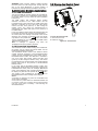
Installer Guide
PowerMax10
Fully supervised wireless alarm control system
PowerMax10-G2
Installer Guide
Wireless Intrusion and Fire Alarm system
TABLE OF CONTENTS
1. INTRODUCTION............................................................ 3
2. SPECIFICATIONS ......................................................... 3
2.1 Functional ................................................................ 3
2.2 Wireless ................................................................... 3
2.3 Electrical .................................................................. 3
2.4 Communication........................................................ 3
2.5 Physical Properties .................................................. 4
3. INSTALLATION.............................................................. 4
3.1 Supplying Power to the Unit .................................... 4
3.1.1 Inserting Backup Battery.................................. 4
3.1.2 Connecting Power to Panel ............................. 4
3.1.3 Telephone Wiring............................................. 4
3.2 System Planning & Programming............................ 6
3.3 Mounting the Unit..................................................... 6
3.4 Extension Modules Installation ................................ 7
3.4.1 GSM Installation ................................................. 7
3.4.2 PowerLink Installation ......................................... 7
3.5 Closing the Control Panel........................................ 7
4. PROGRAMMING ........................................................... 8
4.1 General Guidance ................................................... 8
4.2 Navigation................................................................ 8
4.3 Permissions and User Codes.................................. 8
4.3.1 Setting a New Installer Code ........................... 8
4.3.2 Setting the Master Installer Code .................... 9
4.3.3 Setting User Codes........................................ 10
4.3.4 Enabling User Permit for Installer Access ..... 10
4.3.5 Configuring Permissions for System Reset after
Alarm Event............................................................. 10
4.3.6 Configuring a Duress Code ........................... 11
4.4 Zones / Devices ..................................................... 12
4.4.1 General Guidance.......................................... 12
4.4.2 Adding a Wireless Device.............................. 12
4.4.2.1 Assigning a Location, Zone type and
Chime Option...................................................... 13
4.4.2.2 Configuring Device Parameters ............. 14
4.4.2.3 Zone Types............................................. 14
4.4.2.4 Locations ................................................ 15
4.4.3 Adding Wired Zones ...................................... 16
4.4.4 Deleting a Device........................................... 17
4.4.5 Modifying a Device......................................... 18
4.5 Siren Configuration ................................................ 19
4.5.1 Configuring the Length of Time the Bell is
Allowed to Function................................................. 19
4.5.2 Enabling the Internal Siren............................. 19
4.5.3 Configuring the Period of Strobe Light
Activation................................................................. 20
4.5.4 Enabling Siren Activation upon Telephone Line
Failure ..................................................................... 20
4.6 Event Reporting Configuration .............................. 21
D-302756
4.6.1 General .......................................................... 21
4.6.2 Setup Report Communicators ....................... 21
4.6.2.1 Configuring PSTN / GSM Communicators
............................................................................ 21
4.6.2.2 Configuring GPRS / BB Communicators 22
4.6.3 Configuring Event Reporting to Monitoring
Station. .................................................................... 25
4.6.3.1 Configuring the Types of Events to be
Reported............................................................. 26
4.6.3.2 Configuring the Communicators Report
Sequence ........................................................... 26
4.6.3.3 Configuring Account Numbers to be
Reported to the Monitoring Station .................... 27
4.6.3.4 Configuring the Monitoring Station's
Telephone Numbers and IP Addresses ............. 28
4.6.3.5 Configuring the Report Method (Protocol)
to Monitoring Station .......................................... 30
4.6.3.6 Configuring the Number of Retry Attempts
............................................................................ 30
4.6.3.7 Configuring the Auto Test Report .......... 31
4.6.3.8 Configuring the Event Types to be
Reported to the Monitoring Station .................... 33
4.6.4 Configuring Event Reporting to Users........... 34
4.7 Security System Configuration .............................. 37
4.7.1 Enable Cross Zoning ..................................... 37
4.7.2 Configuring Swinger Stop .............................. 38
4.7.3 Enable Monitoring of Activity at Home........... 39
4.7.4 Configuring Alarm Cancel Period .................. 39
4.7.5 Configuring Power Failure Threshold Period 40
4.7.6 Configuring Abort Time.................................. 40
4.7.7 Configuring a Confirmed Alarm ..................... 41
4.7.8 Enable Alarm upon Detection of Jammed or
Missing Device........................................................ 42
4.7.9 Configuring the Jamming Detection .............. 42
4.7.10 Configuring Whether a Missing Device
Causes the System to Become "NOT READY"...... 43
4.7.11 Configuring the Time Period by which a
Device is considered Missing ................................. 44
4.8 Arming/Disarming Options And Exit/Entry Delay .. 44
4.8.1 Configuring Exit Modes.................................. 44
4.8.2 Configuring Entry Delays Duration ................ 45
4.8.3 Configuring Exit Delay Duration .................... 46
4.8.4 Enabling Quick Arm ....................................... 46
4.8.5 Configuring Bypassing Zones........................ 47
4.8.6 Configuring Panic Alarm Activation ............... 47
4.8.7 Enabling Latchkey Arming ............................. 48
4.9 User Interface Customization ................................ 49
4.9.1 Enabling Trouble Beeps ................................ 49
4.9.2 Enabling Piezo Beeps.................................... 49
4.9.3 Enabling the Back Light ................................. 50
4.9.4 Configuring the Disarm Option ...................... 50
4.9.5 Configuring the Screen Saver Options.......... 51
4.9.6 Enabling the Memory Prompt ........................ 52
1
4.9.7 Enabling Keyfob Low Battery
Acknowledgement................................................... 52
4.10 DEFINE CUSTOM LOCATIONS ......................... 53
4.11 CONFIGURING OUTPUT PARAMETERS ......... 54
4.11.1 Preliminary Guidance................................... 54
4.11.2 Define PGM.................................................. 54
4.12 Programming User Settings ................................ 58
Configuring Remote Programming Access Permissions
..................................................................................... 59
5 DIAGNOSTIC TEST...................................................... 61
5.1 Testing Devices ..................................................... 62
5.1.1 Testing all Devices......................................... 62
5.1.2 Testing One Device ....................................... 62
5.1.3 Displaying Signal Strength Indication of All
Devices ................................................................... 63
5.1.4 Displaying Signal Strength Indication of RF
Devices ................................................................... 63
5.1.5 GPRS Communication Test........................... 64
5.1.6 LAN Connection Test..................................... 65
5.1.7 LAN Reset Option .......................................... 66
6 CALLING UPLOAD/DOWNLOAD SERVER................. 67
7. MAINTENANCE ........................................................... 68
7.1 Handling System Troubles .................................... 68
7.2 Dismounting the Control Panel.............................. 69
7.3 Replacing the Backup Battery ............................... 69
7.4 Fuse Replacement ................................................ 69
7.5 Replacing/Relocating Detectors............................ 69
7.6 Restore Factory Defaults....................................... 69
7.7 Viewing Serial Number .......................................... 70
8 READING THE EVENT LOG........................................ 70
8.1 Reading the Event Log.......................................... 70
8.2 Erasing and Exiting the Event Log ........................ 71
APPENDIX A. Detector Deployment & Transmitter
Assignments..................................................................... 71
A1. Detector Deployment Plan .................................... 71
A2. Keyfob Transmitter List ......................................... 72
A3. Emergency Transmitter List .................................. 72
A4. Non-Alarm Transmitter List ................................... 72
APPENDIX B. Event Codes............................................. 73
B1. Contact ID Event Codes ....................................... 73
B2. SIA Event Codes................................................... 73
B3. 4/2 Event Codes.................................................... 73
B4. Understanding the Scancom Reporting Protocol
Data Format................................................................. 74
APPENDIX C. Glossary ................................................... 74
APPENDIX D. DEFAULT AND PROGRAMMED ZONE
DEFINITIONS .................................................................. 76
MESSAGE TO THE INSTALLER
The PowerMax10-G2 control panel is supplied with 3 instruction manuals:
Installer Guide (this manual - for your exclusive use)
User’s Guide (for your use during installation only - Must be handed over to the master user after testing the system)
Accessories Guide (includes a full description of devices that are supported by the PowerMax10-G2 system)
Appendices A.1 and A.2 will help you prepare an installation plan. Please take time to fill out the forms - your job will
become much easier and confusion will be prevented. Filling out the forms will also help you create a list of detectors and
transmitters that must be obtained for the particular application. Compatible detectors and transmitters are listed in the
Accessories Guide.
Remember - it is advisable to power up the control panel temporarily after unpacking and program it on the work bench, in
accordance with the installation plan.
Although setting the correct time and date is one of the user tasks, we recommend that you set the time and date in the
course of programming. Access to the “User Settings” for the installer is possible through the installer‘s menu or through
the user menu (see User’s Guide section 2).
After programming, proceed to install the system as detailed in the Installation Instructions, from paragraph 3.3 Mounting
the Unit onward.
The installer should verify line seizure. Be aware of other phone line services such as DSL. If DSL service is present on the
phone line, you must install a filter. It is suggested to use the DSL alarm filter model Z-A431PJ31X manufactured by
Excelsus Technologies, or equivalent. This filter simply plugs into the RJ-31X jack and allows alarm reporting without
breaking the internet connection.
2
D-302756
1. INTRODUCTION
The PowerMax10-G2 is a user and installer-friendly, 29zone fully-supervised wireless control system.
The system is designed to function in an appealing way to
the user and also offers features that make installers’ life
easier than ever before:
EASY TO MAINTAIN
• Alarm memory and trouble data are displayed upon
request.
• Diagnostic test provides visual and audible indication of
the signal level of each detector.
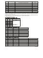
2. SPECIFICATIONS
2.1 Functional
Zones Number: 28 wireless zones, 1 hardwired input.
Hardwired Zone Requirements: 2.2 kΩ E.O.L. resistance
(max. resistance of wires 220 Ω).
Zone Types: Interior follower, interior, perimeter,
perimeter follower, delay 1, delay 2, 24h silent, 24h
audible, fire, non-alarm, emergency, gas, flood,
temperature and home/delay.
User Codes: 8 codes, 4 digits each (9999 different
combinations). Code 0000 is not allowed.
Control Facilities:
- Integral keypad
- PowerG / Code-Secure™ hand-held transmitters.
- Two way keypads.
- SMS commands via optional GSM/GPRS module.
- Remote control by telephone.
Note: For SIA CP-01 compliance, when using KF-234 PG2
an external siren must also be used.
Display: Single line, backlit 16-character LCD.
Arming Modes: AWAY, HOME, AWAY-INSTANT, HOMEINSTANT, LATCHKEY, FORCED, BYPASS.
Alarm inhibited during a single arming period (swinger
stop) after: 1, 2, 3, alarm/tamper/fault, or not inhibited
(programmable / selectable).
Note: To comply with EN requirements, the swinger stop
should be set to 3.
Alarm Types: Silent alarm, siren alarm (future option) or
sounder (internal) alarm, in accordance with zone attributes.
Siren Signals: Continuous (intrusion / 24 hours / panic);
triple pulse - pause - triple pulse... (fire).
Siren (bell) Timeout: Programmable (4 min. by default).
Internal Sounder Output: At least 85 dBA at 10 ft (3 m).
Supervision: Programmable time frame for inactivity alert
Special Functions:
- Chime zones
- Diagnostic test and event log.
- Local and Remote Programming over Telephone, GSM
/GPRS connections.
- Calling for help by using an emergency transmitter.
- Tracking inactivity of elderly, physically handicapped and
infirm people.
Data Retrieval: Alarm memory, trouble, event log.
Real Time Clock (RTC): The control panel keeps and
displays time and date. This feature is also used for the log file
by providing the date and time of each event.
Compliance with U.S. Standards:
USA: (FCC) CFR 47part 15 and part 68, UL 1023, UL 985,
UL 1635, UL 1637, SIA CP-01
Canada: RSS 210, ULC S545-02, ULC C1023,CSA
C22.2#205
D-302756
• Remote control from distant telephones.
• Event log stores and displays information.
• Upload / download from distant computer via telephone
line or cellular modem.
QUICK PROGRAMMING
• Simple programming logic, fully menu driven.
• Multiple-choice selection of options for each parameter.
• Unequivocal visual prompts.
• Installer access to the user menu.
Compliance with European CE Standards:
The PowerMax10-G2 has been certified to EN 50082-1,
EN301489-3,7,
EN61000-4-6,
EN60950,
EN300220,
EN50130-4, EN50130-5, EN50131-3, EN50131-6 tested by
the Dutch testing and certification body Telefication B.V.
The PowerMax10-G2 is compatible with the RTTE
requirements - Directive 1999/5/EC of the European
Parliament and of the Council of 9 March 1999.
According to the European standard EN50131-1, the
PowerMax10-G2 security grading is 2 – "low to medium
risk" and environmental classification is II – "indoor general"
and the power supply type is A.
GSM standards:
Europe: Complies with CE standards 3GPP TS 51.010-1,
EN 301 511, EN301489-7
USA: CFR 47 Part 22 (GSM850) and Part 24 (GSM 1900).
EMC standard: CFR 47 Part 15.
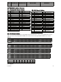
2.2 Wireless
Operating Frequencies (MHz): 315 (in USA & Canada),
433.92, 868.95 or other UHF channel per local
requirement in the country of use.
Receiver Type: Super-heterodyne, fixed frequency
Receiver Range: 600 ft (180 m) in open space
Antenna Type: Spatial diversity
Coding: PowerG and/or CodeSecure™
2.3 Electrical
External AC/AC adapter:
• Europe: 230VAC 50Hz input, 9VAC 700mA output.
• USA: 120VAC 60Hz input, 9VAC 1000mA output.
Current Drain: Approx. 70 mA standby, 1600 mA peak at
full load.
Minimum battery voltage: 4.8V
Note: For CE compliance the battery backup period shall
exceed 12 hours.
Backup Battery Pack: 4.8V 1300 mAh, rechargeable
NiMH battery pack, p/n GP130AAM4YMX, manufactured
by GP or equivalent.
Note: For compliance with UL standards the battery
backup period shall exceed 24 hours.
Backup Battery Pack: 4.8V 2200 mAh, rechargeable
NiMH battery pack, p/n GP230AAHC4YMX, manufactured
by GP.
Battery Test: Once every 10 seconds.
2.4 Communication
Built-in Modem: 300 baud, Bell 103 protocol
Data Transfer to Local Computer: Via RS232 serial port
Report Destinations: 2 Monitoring Stations, 4 private
telephones.
Reporting Format Options: SIA, Pulse 4/2 1900/1400 Hz,
Pulse 4/2 1800/2300 Hz, Contact ID, Scancom.
Pulse Rate: 10, 20, 33 and 40 pps - programmable
Message to Private Phones: Tone
3
Ring Detection: The unit does not support ring detection
without DC voltage present on the telephone lines.
2.5 Physical Properties
Operating Temp. Range: 14°F to 120°F (-10°C to 49°C)
Storage Temp. Range: -4°F to 140°F (-20°C to 60°C)
Humidity: 85% relative humidity, @ 30°C (86°F)
Size: 193 x 178 x 50 mm (7-5/8 x 7 x 2 in.)
Weight: 658g (23 Oz) (with battery)
Color: White
3. INSTALLATION
Note: This system must be checked by a qualified
technician at least once every three (3) years.
3.1 Supplying Power to the Unit
Connect power to the PowerMax10-G2 temporarily (see
Figure 3.2). Alternatively, you may power up from the
backup battery, as shown in Figure 3.1.
Disregard any “trouble” indications pertaining to lack of
battery or lack of telephone line connection.
For Europe Safety Compliance:
a. The model shall be installed according to the local
electrical code.
b. The circuit breaker shall be readily accessible.
c. The rating of the external circuit breaker shall be 16A
or less.
d. The cables for the AC mains connection shall have an
overall diameter of 13mm and 16mm conduit.
Please refer to Figure 3.2 "Power Cable Connection".
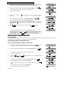
3.1.2 Connecting Power to Panel
Connect the power cable and close the control panel as
shown below. Electrical socket-outlet shall be installed
near the equipment and shall be easily accessible.
WARNING! DO NOT USE AN OUTLET CONTROLLED
BY A WALL SWITCH.
Note: This equipment should be installed in accordance with
Chapter 2 of the National Fire Alarm Code, ANSI/NFPA 72,
(National Fire Protection Association).
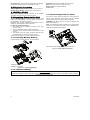
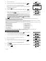
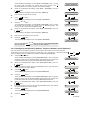
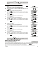
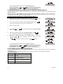
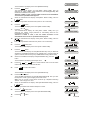
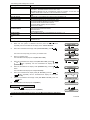
3.1.1 Inserting Backup Battery
Connect battery pack as shown in the next drawing.
1
Connect the power adapter to the power connector.
Fig. 3.2 - Power Cable Connection
2
1. Battery insertion
2. Battery connection
Figure 3.1 – Connecting Battery
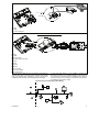
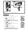
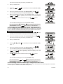
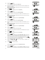
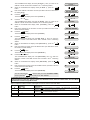
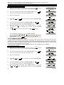
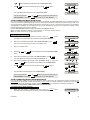
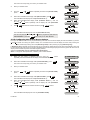
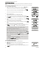
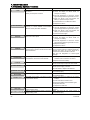
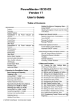
3.1.3 Telephone Wiring
PHONE WIRING
Connect the telephone cable to the SET connector and connect the telephone line cable to the LINE connector (through
the desired wiring cable entry).
4
D-302756
C
A
B
A. SET
B. LINE
C. Tel line wall jack
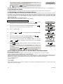
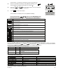
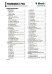
PHONE WIRING IN NORTH AMERICA
B
I
D
A
E
1
F
3 4
F
7
H
6
5
E
J
RJ-31X
G
C
2
G
K
H
A. SET
B. LINE
C. RJ-31X cord
D. 8-position RJ-31X plug
E. Gray
F. Red
G. Green
H. Brown
I. RJ-31X jack
J. Line from street
K. House phones
This equipment is designed to be connected to the telephone
network using RJ11 connector which complies with Part 68
rules and requirements adopted by ACTA and properly
installed RJ31X connector. See drawing below for details.
In the case that RJ31X is not available (consult your
telephone company or a qualified installer), the telephone
line should be connected to the PowerMax10-G2 unit first
and then all other home equipment should be connected to
PowerMax10-G2 "Phone" outlet.
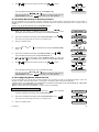
Customer Premises Equipment And Wiring
D
A
J
F
H
B
E
C
E
H
I
G
E
D-302756
5
A. Network Service Provider's Facilities
B. Telephone Line
C. Network Demarcation Point
D. RJ-31X Jack
E. Telephone
F. Alarm Dialing Equipment
G. Answering System
H. Unused RJ-11 Jack
I. Fax Machine
J. Computer
Note: The REN is used to determine the number of devices
that may be connected to a telephone line. Excessive RENs
on a telephone line may result in the devices not ringing in
response to an incoming call. In most but not all areas, the
sum of RENs should not exceed five (5.0). To be certain of
the number of devices that may be connected to a line, as
determined by the total RENs, contact the local telephone
company.
Connection to telephone company provided coin service is
prohibited. Connection to party lines service is subject to
state tariffs.
3.2 System Planning &
Programming
It pays to plan ahead - use the tables in appendices A and
B at the end of this guide to register the intended location
of each detector, the holder and assignment of each
transmitter.
Gather up all transmitters and detectors used in the
system and mark each one in accordance with your
deployment plan.
Program the system now, before mounting, as
instructed in the programming section.
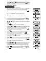
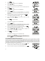
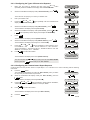
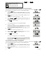
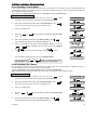
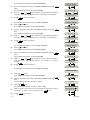
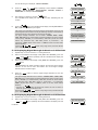
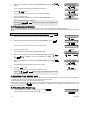
3.3 Mounting the Unit
Required tool: Philips screwdriver #2.
PowerMax10-G2 mounting process is shown in Figure 3.3
- 3.4.
A
B
3
1
A
A
4
A. Mounting surface
B. Back unit
6
5
To Mount the Unit:
1. Release the screws
2. Remove the front cover
3. Mark 4 drilling points on the mounting surface
4. Drill 4 holes and insert wall anchors
5. Fasten the back unit with 4 screws
Figure 3.3 – Back Unit Mounting
D-302756
WARNING! When plugging SIREN & ZONE terminals
back into place, be sure to align them carefully with the
pins on the PCB. Misaligned or reverse insertion of
terminals may damage internal PowerMax10-G2 circuits!
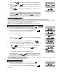
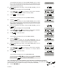
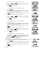
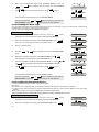
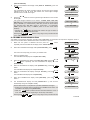
3.5 Closing the Control Panel
Control panel final closure is shown below.
3.4 Extension Modules Installation
3.4.1 GSM Installation
The internal GSM 350 module enables the PowerMax10G2 system to operate over a GSM/GPRS cellular network
(for further details, see the GSM 350 PG2 Installation
Instructions).
The GSM modem auto detection feature enables
automatic enrollment of the GSM modem into the
PowerMax10-G2 control panel memory. GSM modem auto
detection is activated in one of two ways: after tamper
restore and after reset (power-up or after exiting the
installer menu). This causes the PowerMax10-G2 to
automatically scan GSM COM ports for the presence of
the GSM modem.
In the event that the GSM modem auto detection fails and
the modem was previously enrolled in the PowerMax10G2 control panel, the message "Cel Rmvd Cnfrm" will be
displayed. This message will disappear from the display
I OK button. The modem
only after the user presses the
is then considered as not enrolled and no GSM trouble
message will be displayed.
Note: A message is displayed only when the
PowerMax10-G2 alarm system is disarmed.
1
To Close the Control Panel:
1. Close the front cover
2. Fasten the screws
Figure 3.4 - Final Closure
3.4.2 PowerLink Installation
The PowerLink module enables viewing the PowerMax10G2 system over the internet (for further details, see the
PLINK PRO Installation Instructions).
The Broadband Module modem auto detection feature
enables automatic enrollment of the Broadband Module
modem into the PowerMax10-G2 control panel memory.
Broadband Module modem auto detection is activated in
one of two ways: after tamper restore and after reset
(power-up or after exiting the installer menu). This causes
the PowerMax10-G2 to automatically scan the Broadband
Module COM ports for the presence of the Broadband
Module modem.
In the event that the Broadband Module modem auto
detection fails and the modem was previously enrolled in the
PowerMax10-G2 control panel, the message "BBA Remvd
Cnfrm" will be displayed. This message will disappear from
I OK button.
the display only after the user presses the
The modem is then considered as not enrolled and no
Broadband Module trouble message will be displayed.
Notes:
A message is displayed only when the PowerMax10-G2
alarm system is disarmed.
In the event of a power failure the Broadband Module will
not operate. Power (AC or battery) must be disconnected
from the circuit before connecting / disconnecting the
Broadband Module.
D-302756
7
4. PROGRAMMING
4.1 General Guidance
We recommend programming the PowerMax10-G2 on the work bench before actual installation. Operating power may be
obtained from the backup battery or from the AC power supply.
4.2 Navigation
This mode allows you to customize the control panel and adapt its characteristics and behavior to the requirements of the
particular user. To review the options within the control panel menus, repeatedly press the
button, until the
or
I OK button.
desired option is displayed, then press the
You will mainly use 5 control pushbuttons during the entire programming process:
- to move one step forward in a menu.
- to move one step backward in a menu.
I OK
- to enter the relevant menu or confirm data.
- to move one level up in a menu.
- to return to the "OK TO EXIT" state.
The sounds you will hear while programming are:
- Single beep, heard whenever a key is pressed.
☺
- Double beep, indicates automatic return to
the normal operating mode (by timeout).
- Happy Melody (- - - –––), indicates successful
completion of an operation.
- Sad Melody (–––––), indicates a wrong move
or rejection.
If you enter an invalid installer code 5 times, the keypad will be automatically disabled for 90 seconds and the message
WRONG PASSWORD will be displayed.
4.3 Permissions and User Codes
The PowerMax10-G2 system includes four code levels, as follows:
• Installer Code: By using the installer code, the menu enables changing the installer code.
• Master Installer Code: By using the master installer code, the menu enables changing both master installer code and
installer code.
• User Code: See PowerMax10-G2 User Guide
• Master User Code: See PowerMax10-G2 User Guide
Not every system includes a MASTER INSTALLER code. In a system with an INSTALLER code only, the installer can use all
the functions in the system.
The following actions can be done only by using the master installer code:
• Changing master installer code.
• Resetting the PowerMax10-G2 parameters to the default parameters,
• Defining specific communication parameters.
You are expected to use this code only once for gaining initial access, and replace it with a secret code known only to
yourself.
4.3.1 Setting a New Installer Code
To set an installer code, perform the actions that are presented below. When you are instructed to enter code, enter a 4digit code.
A. To Set a New Installer Code
1.
Make sure the system is disarmed and then press the
button repeatedly
until the PowerMax10-G2 display reads "INSTALLER MODE".
2.
When the PowerMax10-G2 display reads [INSTALLER MODE], press
I OK
.
READY 00:00
INSTALLER MODE
I OK
The screen will now prompt you to enter your installer code.
∗
8
∗
ENTER CODE:
The default Installer Code is 9999.
D-302756
3.
Enter your Installer Code.
4.
When the PowerMax10-G2 display reads [NEW INSTL CODE], press
CODE
I OK
.
NEW INSTL CODE
I OK
The PowerMax10-G2 display will read [NEW MASTER CODE].
NEW MASTER CODE
Note: The menu displays within the dashed box appear only if the control panel
includes the Master Installer Code.
5.
Press the
6.
When the PowerMax10-G2 display reads [NEW INST. CODE], press
button.
I OK
.
NEW INST. CODE
I OK
7.
Enter the new 4-digit Installer Code (8888 or 9999) at the position of the blinking
I OK .
cursor and then press
The PowerMax10-G2 display reads [NEW INST. CODE] and a "Happy Tune" ☺
sounds to confirm the new Installer Code.
If your system uses MASTER CODE, you should proceed to setting the MASTER
INSTALLER code in section 4.3.2 by pressing the
button, or press the
button to take you to "<OK> TO EXIT".
INST. CODE
888
I OK
NEW INST. CODE
☺
Note: Installer Code should never be programmed as “0000”. Doing so will lock the user out of the installer menu!
4.3.2 Setting the Master Installer Code
For PowerMax10-G2 with MASTER INSTALLER code, set a new INSTALLER code as described in section 4.3.1 "Setting a
New Installer Code" and set the MASTER INSTALLER code as described in this section.
Note: For Control Panel that has installer code & master installer code, the following functions are available only if the
MASTER INSTALLER code is entered:
• PSTN/GSM RCVR1
• RPRT CNFRM ALRM
• RCVR 1 ACCOUNT#
• SEND 2WV CODE
• PSTN/GSM RCVR2
• VOICE Monitoring Station.
• RCVR 2 ACCOUNT#
• RINGBACK TIME
• PSTN RPRT FORMAT
• PSTN RPRT RETRY
• 4/2 PLS RATE
• GSM RPRT RETRY
• REPORT EVENTS
• MAST. DL CODE
By using the master installer code, the menu enables changing both master installer code and installer code.
By using the installer code, the menu enables changing the installer code only.
B. To Set a New Master Installer Code
1.
Make sure the system is disarmed and then press the
button repeatedly
until the PowerMax10-G2 display reads "INSTALLER MODE".
2.
When the PowerMax10-G2 display reads [INSTALLER MODE], press
I OK
.
READY 00:00
INSTALLER MODE
I OK
The screen will now prompt you to enter your installer code.
∗
3.
Enter your Installer Code.
4.
When the PowerMax10-G2 display reads [NEW INSTL CODE], press
ENTER CODE:
CODE
I OK
.
NEW INSTL CODE
I OK
The PowerMax10-G2 display will read [NEW MASTER CODE].
5.
Press
6.
Enter the new 4-digit Installer Code at the position of the blinking cursor and
I OK .
then press
D-302756
I OK
.
NEW MASTER CODE
I OK
MASTER CODE 999
I OK
9
The PowerMax10-G2 display reads [NEW MASTER CODE] and a "Happy Tune" ☺
sounds to confirm the new MASTER INSTALLER code.
NEW MASTER CODE
☺
You can now press the
button to set the INSTALLER code or press the
button to take you to "<OK> TO EXIT".
Note: Master Installer Code should never be programmed as “0000”. Doing so will lock the user out of the installer menu!
4.3.3 Setting User Codes
For detailed instructions on setting user codes, refer to the PowerMax10-G2 user guide "Menus and Functions".
4.3.4 Enabling User Permit for Installer Access
User Permission enables you to determine whether access to the INSTALLER MODE requires user permission. Access to
the installer menu, in PowerMax10-G2 that has "User Permission" enabled (for example, in UK) is via the last menu in the
user menu. This option can be changed, if necessary. Here you determine whether the access to the INSTALLER MODE
requires user permission. If you select ENABLE, the installer mode will be accessible only through the user menu after
entering the user code.
Options: Enable (default in UK), Disable (default).
Note: To comply with EN requirements, "Enable" must be selected.
To Enable User Permit for Installer Access
1.
Make sure the system is disarmed and then press the
button
repeatedly until the PowerMax10-G2 display reads "INSTALLER MODE".
2.
When the PowerMax10-G2 display reads [INSTALLER MODE], press
I OK
.
READY 00:00
INSTALLER MODE
The screen will now prompt you to enter your installer code.
3.
I OK
Enter your Installer Code.
ENTER CODE:
CODE
4.
Press the
option.
or
button repeatedly and select the [DEFINE PANEL]
DEFINE PANEL
5.
When the PowerMax10-G2 display reads [DEFINE PANEL], press
6.
When the PowerMax10-G2 display reads [01:ENTRY DELAY 1], press the
or
button repeatedly until the display will read [36:USER
PERMIT].
Press
press
I OK
I OK
I OK
I OK
The PowerMax10-G2 display will read [01:ENTRY DELAY 1].
7.
or
01:ENTRY DELAY 1
or
36:USER PERMIT
and select between "Disable" (default) and "Enable" and then
to confirm.
The PowerMax10-G2 display reverts to "36:USER PERMIT" and a "Happy Tune"
☺ sounds.
You can now press the
"DEFINE PANEL" or press the
or
I OK
36:USER PERMIT
button to program any other menu in
button to take you to "<OK> TO EXIT".
☺
4.3.5 Configuring Permissions for System Reset after Alarm Event
(Not applicable in the USA)
Here you determine whether the system can be rearmed (after an event) by the user or only by the installer.
Options: user reset (default), engineer reset, or anti code reset.
If Engineer Reset is selected, the system can be rearmed only by the installer; by entering and exiting the installer menu, by
entering and exiting the event log (see section 8), or by remote telephone. To perform Engineer Reset via the telephone,
establish communication with the PowerMax10-G2 (see user guide, Chapter 5) and continue as follows:
a. [*], [installer code], [#]
b. Wait for 2 beeps
c. [*], [1], [#]
d. [*], [99], [#]
Visonic uses Technistore anti code reset. Installers should check with their Monitoring Station for a code version (seed
code) which needs to be entered.
10
D-302756
To Configure Permissions for System Reset after an Alarm Event
1.
Make sure the system is disarmed and then press the
button
repeatedly until the PowerMax10-G2 display reads "INSTALLER MODE".
2.
When the PowerMax10-G2 display reads [INSTALLER MODE], press
I OK
.
The screen will now prompt you to enter your installer code.
3.
READY 00:00
INSTALLER MODE
I OK
2
Enter your Installer Code.
ENTER CODE:
CODE
4.
5.
Press the
option.
or
button repeatedly and select the [DEFINE PANEL]
DEFINE PANEL
When the PowerMax10-G2 display reads [DEFINE PANEL], press
I OK
I OK
The PowerMax10-G2 display will read [01:ENTRY DELAY 1].
6.
7.
01:ENTRY DELAY 1
When the PowerMax10-G2 display reads [01:ENTRY DELAY 1], press the
or
button repeatedly until the display will read [25:RESET
OPTIONS].
Press
I OK
or
and make the selection and then press
I OK
to confirm.
or
25:RESET OPTION
I OK
The PowerMax10-G2 display reverts to "25:RESET OPTION" and a "Happy Tune"
☺ sounds.
You can now press the
"DEFINE PANEL" or press the
or
button to program any other menu in
button to take you to "<OK> TO EXIT".
25:RESET OPTION
☺
4.3.6 Configuring a Duress Code
A duress alarm (ambush) message can be sent to the Monitoring Station if the user is forced to disarm the system under
violence or menace. To initiate a duress message, the user must disarm the system with the duress code (2580 by default).
Here you can change the code digits or enter "0000" to disable the duress feature. The system does not allow the user to
program the duress code saved in this memory location as an existing user code.
Note: Duress Code is not applicable in the UK.
To Configure a Duress Code
1.
Make sure the system is disarmed and then press the
button
repeatedly until the PowerMax10-G2 display reads "INSTALLER MODE".
2.
When the PowerMax10-G2 display reads [INSTALLER MODE], press
I OK
.
The screen will now prompt you to enter your installer code.
3.
READY 00:00
INSTALLER MODE
I OK
Enter your Installer Code.
ENTER CODE:
CODE
4.
5.
Press the
option.
or
button repeatedly and select the [DEFINE PANEL]
When the PowerMax10-G2 display reads [DEFINE PANEL], press
DEFINE PANEL
I OK
The PowerMax10-G2 display will read [01:ENTRY DELAY 1].
6.
7.
When the PowerMax10-G2 display reads [01:ENTRY DELAY 1], press the
or
button repeatedly until the display will read [23:DURESS].
I OK , change the code or enter 0000 to disable the duress function
Press
I OK to confirm.
and then press
D-302756
or
I OK
01:ENTRY DELAY 1
or
23:DURESS
I OK
11
The PowerMax10-G2 display reverts to "23:DURESS" and a "Happy Tune" ☺
sounds.
You can now press the
"DEFINE PANEL" or press the
or
23:DURESS
☺
button to program any other menu in
button to take you to "<OK> TO EXIT".
4.4 Zones / Devices
4.4.1 General Guidance
The ZONES / DEVICES mode enables the following functions:
- Defining default parameters common for each devices family.
- Adding new devices (enrolling) and defining their zones name, zone type and chime zone.
- Deleting devices.
- Modifying devices parameters.
- Reviewing devices parameters.
Enrolling can be performed for Keyfobs (multi-button), wireless detectors, wireless sirens and repeaters.
The control panel enables entering a device identification (ID) instead of enrolling an actual device. This enables pre-enrolling off
site.
Upon boot up, the control panel checks if there are pre-enrolled devices that have not yet been registered (ID of the devices are
entered but the devices have not communicated with the control panel). In this case, the control panel will display "SYNC WITH
DEV" on the LCD and the trouble LED will be on until all the devices have registered or the pre-enrolled devices that have not
registered will be deleted from the enrollment menu.
Refer to sections 4.4.3 and 4.4.4 for detailed instructions on Enrolling/Deleting a device.
Notes
- Keyfob enrolling can be performed also by the user (via USER SETTINGS menu).
- Wired magnetic contact or any other contact can be enrolled in zones 29 & 30.
- Wireless detectors can be enrolled in zones 01-28.
Before beginning, gather all the devices that you intend to enroll and make sure they all have batteries installed.
Your control panel must recognize the unique identification code (ID) of each such detector in order to supervise them,
receive their signals and respond accordingly.
• Before enrolling, the lens at the front of PIR and dual-technology sensors should be masked to prevent inadvertent
transmission.
• Make sure that magnetic contact transmitters are together with their magnets, to prevent them from sending out alarm
transmissions.
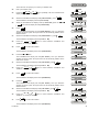
4.4.2 Adding a Wireless Device
This section describes how to add a new device to the PowerMax10-G2 control panel.
Note: It is much easier to enroll the device while holding the device in your hand, close to the control panel.
A. To Add a Device
1.
Make sure the system is disarmed and then press the
button
repeatedly until the PowerMax10-G2 display reads "INSTALLER MODE".
2.
When the PowerMax10-G2 display reads [INSTALLER MODE], press
I OK
.
READY 00:00
INSTALLER MODE
I OK
The screen will now prompt you to enter your installer code.
3.
ENTER CODE:
Enter your Installer Code.
CODE
The PowerMax10-G2 display will read [NEW INSTL CODE].
4.
Press the
NEW INSTL CODE
button and select the [ZONES/DEVICES] option.
ZONES/DEVICES
5.
When the PowerMax10-G2 display reads [ZONES/DEVICES] press
I OK
The PowerMax10-G2 display will read [ADD NEW DEVICES].
6.
Press
7.
Enter the 7-digit number printed on the back side of the device and press
I OK
I OK
. You are now instructed to enroll the device.
.*
or
Perform the enrollment sequence for the specific device:
For most devices: Remove the device bracket or cover and press the device's
12
I OK
ADD NEW DEVICES
I OK
ENROLL NOW or
ENTER ID No
I OK
D-302756
Enroll button continuously until the red & green LEDs turn ON and then release.
The PowerMax10-G2 will indicate the result on its LCD display.
For Keyfobs: Press the '*' button until the red LED blinks rapidly and then release
(the LED will continue blinking) then press the same button again. The LED lights
green and the PowerMax10-G2 will indicate the result on its LCD display.
The PowerMax10-G2 display reads [DEVICE ENROLLED] (or [ID accepted] if
the device was enrolled manually by entering the ID number), a "Happy Tune" ☺
sounds and the PowerMax10-G2 display will then change to [K01:Keyfob /
Z01:Motion Sens / S01:Siren depending on the type of enrolled device].
However, if the device was previously enrolled in the system, the PowerMax10G2 display reads [ALREADY ENROLLED].
Repeat the above procedure for each device to be enrolled in the PowerMax10G2 system.
Continue to section 4.4.2.1 Assigning a Location, Zone Type and Chime Option.
When exiting "ZONES / DEVICES" menu the PowerMax10-G2 system displays the
number of devices that need to be updated, as follows: DEV UPDATING NNN.
* If you enter the 7-digit number, you must physically install the device to
complete the procedure. If the device is not installed, the system will display
the device as "NOT NET" (device is pre-enrolled – not networked).
DEVICE ENROLLED
☺
K01:Keyfob
Z01:Motion Sens
……..
S01:Siren
You can now press the
button to enroll the next device of the same type or
I OK button to move to the "LOCATION" menu (see section 4.4.2.1) or
press the
press the
button to take you to "<OK> TO EXIT".
ALREADY ENROLLED
4.4.2.1 Assigning a Location, Zone type and Chime Option
B. To Assign a Location, Zone Type and Chime Option
The PowerMax10-G2 system behavior is defined according to one of 15 zone types assigned to each of the system's 30
(wireless & wired) zones.
Note: This step is applicable to detectors only.
Continue below from the previous section.
. The PowerMax10-G2 display will read [Z01: LOCATION].
1.
Press
2.
When the PowerMax10-G2 display reads [LOCATION], press
I OK
I OK
Z01: LOCATION
.
I OK
The PowerMax10-G2 display will read [Front door].
Front door
3.
or
button repeatedly to select a location, or, enter the
Press the
location number, for example, "Master Bdrm".
4.
Press
TYPE].
5.
When the PowerMax10-G2 display reads [Z01: ZONE TYPE], press
or
Master Bdrm
I OK
to confirm. The PowerMax10-G2 display will read [Z01:ZONE
I OK
.
The PowerMax10-G2 display will read [12.Non-Alarm].
I OK
Z01:ZONE TYPE
I OK
12.Non-Alarm
6.
or
button repeatedly to select a zone type, or, enter
Press the
the zone type number, for example, pressing 03 selects "3. Home Delay".
To understand the behavior of each zone, see section 4.4.2.3 Zone Types.
or
3. Home Delay
I OK
to confirm. The PowerMax10-G2 display will read [SET CHIME].
7.
Press
8.
I OK to change chime settings or press the
button to skip.
Press
I OK , the PowerMax10-G2 display will read [chime OFF
After pressing
].
9.
I OK
and
Press the
"melody-chime".
D-302756
buttons to select between "CHIME OFF" and
Z01: SET CHIME
I OK
Chime off
or
13
In "melody chime" mode when a chime zone is triggered, chime melody is
heard
10.
Press
I OK
to confirm.
I OK
The PowerMax10-G2 display will read [DEV SETTINGS].
11.
Press the
Z01:DEV SETTINGS
button.
The PowerMax10-G2 display will read [NEXT device]*.
12.
Press the
NEXT device
button.
The PowerMax10-G2 display will read [MODIFY SAME Dev.]*.
13.
Press the
melody-chime
MODIFY SAME Dev.
button.
The PowerMax10-G2 display will read [EXIT Enrollment]*.
EXIT Enrollment
* When the PowerMax10-G2 will read "NEXT device" you can click the
button to enroll the next device. When the PowerMax10-G2 will read "MODIFY
I OK button to modify the same device. When the
SAME Dev" you can click the
I OK button
PowerMax10-G2 will read "EXIT Enrollment" you can click the
to revert to "ADD NEW DEVICES".
I OK
4.4.2.2 Configuring Device Parameters
Refer to the PowerMax10-G2 Accessories Guide for detailed instructions on how to modify specific device settings for each
device
4.4.2.3 Zone Types
Upon enrollment of a new detector (marked "Zxx") you must select the proper zone type. The zone type determines how the
system handles alarms and other signals sent from the device.
A list of factory defaults is printed in Appendix D. You may fill out the blank columns even before you start and proceed to
program according to your own list.
Zone types are fully explained below:
Delay Zones:
A delay zone has exit and entry delays set by you in the course of programming the system. Warning beeps will sound
throughout these delays, unless you choose to mute them.
• Exit Delay - The exit delay begins once the user arms the system. It allows him to leave via interior zones and a doorway
before arming actually takes effect. When the exit delay starts, the buzzer beeps slowly and maintains a slow beeping rate
until the last 10 seconds, during which it beeps rapidly. The PowerMax10-G2 has two types of delay zones, for which
different delay times may be set.
• Entry Delay - The entry delay begins once the user enters the protected area via a specific doorway (his entry is sensed
by a delay zone detector). To avoid an alarm, he must reach the keypad via interior zones (which become "follower
zones" during the entry delay) and disarm the system before the delay expires. When the entry delay starts, the buzzer
beeps slowly until the last 10 seconds, during which it beeps rapidly.
Remember!
A delay zone is also a perimeter zone by definition.
Emergency Zones:
You can provide incapacitated, sick or elderly people with a miniature single-button transmitter to be carried on the neck
like a pendant or to be worn on the wrist like a watch. In distress situations, they can press the button on their transmitter,
causing the PowerMax10-G2 to send an emergency call to the Monitoring Station or to private telephones designated by
the installer.
To make this possible, define the required number of zones as emergency zones and enroll a portable transmitter to each
one of these zones. When completed, ask the master user to distribute these transmitters to their potential users.
Fire Zones:
A fire zone uses smoke detectors and is permanently active (a fire alarm is triggered regardless of whether the system is
armed or disarmed). Upon detection of smoke, a pulsating siren sounds immediately and the event is reported via the
telephone line.
Flood Zone:
A flood zone is permanently active (a flood alarm is triggered regardless of whether the system is armed or disarmed).
Upon detection of flood leak, the event is reported via the telephone line.
Gas Zone:
A gas zone is permanently active (a gas alarm is triggered regardless of whether the system is armed or disarmed). Upon
detection of gas leak, the event is reported via the telephone line.
Interior Zone:
14
D-302756
Interior zones are zones within the protected premises that have nothing to do with perimeter protection. Their most
important feature is that they allow free movement within the protected area without initiating an alarm, provided that the
system is armed in the "HOME" mode. People can therefore stay at home and move about freely, as long as they do not
disturb a PERIMETER zone.
Once the system is armed in the AWAY mode (all zones are protected), interior zones will initiate an alarm if violated.
Interior Follower Zones:
"Interior Follower" zone is a zone that is located between entry/exit zone and the alarm system control panel. This zone is
temporarily ignored by the alarm system during entry/exit delay periods, to enable you to walk (without causing an alarm) in
front of a motion detector that is associated with the Interior Follower zone, after you enter through an entry zone on the
way to the control panel, or when leaving the protected premises after system arming.
Home/Delay Zones:
A zone type which functions as a delay zone when the system is armed HOME and as a perimeter-follower zone when the
system is armed AWAY.
Non-Alarm Zones:
A non-alarm zone does not directly participate in the alarm system. It can be used for chime or for optional KEY ON-OFF
feature (when enabled).
You can define the desired number of non-alarm zones and enroll a portable transmitter or a wireless device (detector) to this
type of zone.
Perimeter Zones:
Perimeter zones rely on detectors designed to protect doors, windows and walls. An immediate alarm is initiated when
such a zone is violated by opening the door/window or by trying to break the wall.
Perimeter Follower Zones:
A non-entry/exit zone, typically a perimeter zone located on an entry/exit path, that is treated as an entry/exit zone during
an entry/exit time.
Temperature Zone:
A temperature zone uses a wireless temperature detector to detect both indoor and outdoor temperatures and is permanently
active. The detector monitors room temperature using an internal sensor. For outdoor or refrigerator installations, a waterproof
temperature probe (optional) is used. There are a total of four fixed temperature points and the user can enable one or more
temperature points.
Upon detection of change in temperature a digital message is transmitted and the event is reported.
24-Hour Zones:
24 hour zones are mainly used for PANIC buttons, perimeter detectors and anti-tamper protection. They therefore trigger an
alarm in both armed and disarmed states.
• 24 Hour Zone - Silent. - Upon detection, this zone initiates a silent alarm, meaning that the sirens do not function.
Instead the PowerMax10-G2 dials telephone numbers and reports the event to Monitoring Stations and/or to private
telephones, as programmed.
• 24 Hour Zone - Audible. - Upon detection, this zone initiates a siren alarm. The PowerMax10-G2 also dials telephone
numbers and reports the event to Monitoring Stations and/or to private telephones, as programmed.
Key Zones (Optional):
Key zones are zones that can be used for arming and disarming the system by MCT-100 and MCT-102 PowerG transmitters
that are enrolled to a zone. In addition, the alarm system may be armed / disarmed by a keyswitch when connected to wired
zones 29 and 30.
Defining a zone as a KEY ZONE includes the following actions:
a. The zone should be defined as non-alarm type zone.
b. "Z-KEY ENABLE" should be selected for such a zone.
c. According to the zone number, "z. 21-28 enable", "z.29-30 enable", or "z. 21-30 enable" should be selected in the
DEFINE PANEL menu.
4.4.2.4 Locations
You can select or assign a named location to a device (e.g. Garage, Front Door etc.). 31 locations can be selected, 26
fixed names and 5 custom names (defined by the installer).
Note: Custom Locations can be defined via the DEFINE CUSTOM menu, and these custom names will also appear on
your location list in addition to the default names.
Note: To facilitate assigning a location name to a device, a shortcut procedure may be used by entering the location
number which takes you directly to the location name.
Selectable Locations:
Attic
Downstairs
Back door
Emergency
Basement
Fire
Bathroom
Front door
Bedroom
Garage
Child room
Garage door
Closet (UK: Conservatory)
Guest room
Den (UK: Playroom)
Hall
Dining room
Kitchen
D-302756
15
Laundry room
Living room
Master bath
Master bdrm
Office (UK: Study)
Upstairs
Utility room
Yard (UK: Garden)
Custom 1
Custom 2
Custom 3
Custom 4
Custom 5
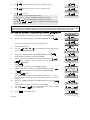
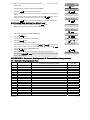
4.4.3 Adding Wired Zones
Required tools: Cutter and slotted screwdriver - 3 mm blade.
PowerMax10-G2 wiring is shown in Figure 4.1.
CABLES ROUTING GUIDE
A
B
A. Cables entry options
B. Back unit
C. Cable clips
16
C
1
2
To Route the Cable:
1. Remove the left or right side cables entry knockout(s)
and enter the required cable(s)
2. Remove and use as cable clamp(s)
D-302756
ZONE WIRING
A
B
2.2kΩ
2.2kΩ
C
A. ZONE
B. TAMPER
C. ALARM
Note: Do not use mains cable other than that supplied by the manufacturer (3 m long).
Figure 4.1 - Wiring
4.4.4 Deleting a Device
C. To Delete a Device
1.
Repeat steps 1 to 5 in section 4.4.3 "Adding a Device".
2.
When the PowerMax10-G2 display reads [ADD NEW DEVICES] press the
button.
ADD NEW DEVICES
The PowerMax10-G2 display will read [DELETE DEVICES].
DELETE DEVICES
3.
Press
I OK
.
I OK
The PowerMax10-G2 display will read [CONTACT SENSORS].
4.
5.
6.
7.
Press the
or
button repeatedly to select the type of device to be
deleted. Select between "CONTACT SENSORS", "MOTION SENSORS", "SMOKE
SENSORS", "WIRED SENSORS", "KEYFOBS", "SIRENS" and "REPEATERS" for
example, "MOTION SENSORS".
Press the
I OK
button.
or
MOTION SENSORS
I OK
The PowerMax10-G2 display will read [Z01:Motion Sens].
Z01:Motion Sens
or
button repeatedly to select the motion sensor to be
Press the
deleted, for example, "Z03:Motion Sens".
Z01:Motion Sens
Press the
I OK
button.
The PowerMax10-G2 display will read [<OFF> to delete].
8.
CONTACT SENSORS
Press the
or
I OK
<OFF> to delete
button.
The PowerMax10-G2 display will revert to [MOTION SENSORS].
MOTION SENSORS
The device is deleted from the PowerMax10-G2 system.
When exiting "ZONES / DEVICES" menu the PowerMax10-G2 system displays the
number of devices that need to be updated, as follows: DEV UPDATING NNN.
D-302756
17
I OK button to delete the device of the same type, or
You can now press the
press the
button to delete a different device, or press the
button to
take you to "<OK> TO EXIT".
4.4.5 Modifying a Device
D. To Modify a Device
Note: This procedure is applicable to detectors only.
1.
button
Make sure the system is disarmed and then press the
repeatedly until the PowerMax10-G2 display reads "INSTALLER MODE".
2.
When the PowerMax10-G2 display reads [INSTALLER MODE], press
I OK
.
READY 00:00
INSTALLER MODE
I OK
The screen will now prompt you to enter your installer code.
3.
Enter your Installer Code.
4.
Press the
ENTER CODE:
CODE
button and select the [ZONES/DEVICES] option.
ZONES/DEVICES
5.
When the PowerMax10-G2 display reads [ZONES/DEVICES] press
I OK
I OK
The PowerMax10-G2 display will read [ADD NEW DEVICES].
6.
When the PowerMax10-G2 display reads [ADD NEW DEVICES], press the
or
button repeatedly until the display will read [MODIFY
DEVICES].
7.
Press
I OK
.
9.
I OK
or
button repeatedly to select the desired sensor to be
Press the
modified. Select between "CONTACT SENSORS", "MOTION SENSORS", "SMOKE
SENSORS" and "WIRED SENSORS", for example, "MOTION SENSORS".*
When the PowerMax10-G2 display reads [Z01:Motion Sens] press
I OK
.
The PowerMax10-G2 display will read [LOCATION].
10.
Press
11.
When the PowerMax10-G2 display reads [LOCATION], press
I OK
CONTACT SENSORS
or
Z01:Motion Sens
I OK
. The PowerMax10-G2 display will read [Z01: LOCATION].
I OK
Z01: LOCATION
.
I OK
The PowerMax10-G2 display will read [Front door].
12.
or
MODIFY DEVICES
The PowerMax10-G2 display will read [CONTACT SENSORS].
8.
ADD NEW DEVICES
Front door
or
button repeatedly to select a location, or, enter the
Press the
location number, for example, "Master Bdrm".
or
Master Bdrm
13.
Press
TYPE].
14.
When the PowerMax10-G2 display reads [Z01: ZONE TYPE], press
I OK
to confirm. The PowerMax10-G2 display will read [Z01:ZONE
I OK
.
The PowerMax10-G2 display will read [12.Non-Alarm].
I OK
Z01:ZONE TYPE
I OK
12.Non-Alarm
15.
or
button repeatedly to select a zone type, or, enter
Press the
the zone type number, for example, pressing 03 selects "3. Home Delay".
To understand the behavior of each zone, see section 4.4.2.3 Zone Types.
or
3. Home Delay
I OK
16.
Press
I OK
17.
Press
I OK
18
to confirm. The PowerMax10-G2 display will read [SET CHIME].
to change chime settings or press the
button to skip.
Z01: SET CHIME
I OK
D-302756
After pressing
18.
19.
I OK
, the PowerMax10-G2 display will read [chime OFF
].
and
buttons to select between "CHIME OFF" and
Press the
"melody-chime".
In "melody chime" mode when a chime zone is triggered, chime melody is
heard
I OK
to
Press
[DEV SETTINGS].
confirm.
The
PowerMax10-G2
display
will
Chime OFF
or
melody-chime
read
I OK
Z01:DEV SETTINGS
You can now press the
button to modify the next device of the same type,
I OK button to configure the parameters of the device (see the
or press the
Accessories Guide for instructions), or press the
button to take you to
"<OK> TO EXIT".
4.5 Siren Configuration
4.5.1 Configuring the Length of Time the Bell is Allowed to Function
Here you select the length of time the bell (or siren) is allowed to function upon alarm. The bell time starts upon activation
of the siren. Once the bell time expires, the siren is automatically shut down.
Available options are: 1, 3, 4 (default), 8, 10, 15 and 20 minutes.
Note: To comply with EN requirements, the Bell Time should be set to 15 min. max.
To Configure the Length of Time the Bell is Allowed to Function
1.
Make sure the system is disarmed and then press the
button
repeatedly until the PowerMax10-G2 display reads "INSTALLER MODE".
2.
When the PowerMax10-G2 display reads [INSTALLER MODE], press
I OK
.
The screen will now prompt you to enter your installer code.
3.
READY 00:00
INSTALLER MODE
I OK
Enter your Installer Code.
ENTER CODE:
CODE
4.
5.
Press the
option.
or
button repeatedly and select the [DEFINE PANEL]
DEFINE PANEL
When the PowerMax10-G2 display reads [DEFINE PANEL], press
I OK
I OK
The PowerMax10-G2 display will read [01:ENTRY DELAY 1].
01:ENTRY DELAY 1
6.
When the PowerMax10-G2 display reads [01:ENTRY DELAY 1], press the
or
button repeatedly until the display will read [04:BELL TIME].
7.
Press
I OK
or
and make the selection and then press
I OK
to confirm.
or
04:BELL TIME
I OK
SELECT OPTION
I OK
The PowerMax10-G2 display will revert to [04:BELL TIME].
You can now press the
"DEFINE PANEL" or press the
or
04:BELL TIME
button to program any other menu in
button to take you to "<OK> TO EXIT".
4.5.2 Enabling the Internal Siren
Here you determine whether the internal siren will sound or remain silent upon alarm (according to the user preference).
Options: piezo siren on (default), piezo siren off.
To Enable the Internal Siren
1.
Make sure the system is disarmed and then press the
button
repeatedly until the PowerMax10-G2 display reads "INSTALLER MODE".
2.
When the PowerMax10-G2 display reads [INSTALLER MODE], press
D-302756
I OK
.
READY 00:00
INSTALLER MODE
19
The screen will now prompt you to enter your installer code.
3.
I OK
Enter your Installer Code.
ENTER CODE:
CODE
4.
Press the
option.
or
button repeatedly and select the [DEFINE PANEL]
DEFINE PANEL
I OK
5.
When the PowerMax10-G2 display reads [DEFINE PANEL], press
6.
When the PowerMax10-G2 display reads [01:ENTRY DELAY 1], press the
or
button repeatedly until the display will read [24:PIEZO
SIREN].
I OK
The PowerMax10-G2 display will read [01:ENTRY DELAY 1].
7.
Press
I OK
or
and make the selection and then press
I OK
01:ENTRY DELAY 1
to confirm.
or
24:PIEZO SIREN
I OK
SELECT OPTION
I OK
The PowerMax10-G2 display will revert to [24:PIEZO SIREN].
You can now press the
"DEFINE PANEL" or press the
or
24:PIEZO SIREN
button to program any other menu in
button to take you to "<OK> TO EXIT".
4.5.3 Configuring the Period of Strobe Light Activation
Here you can define the period of strobe light activation when the siren is in alarm state.
Options: 5 minutes, 10 minutes, 20 minutes (default), 40 minutes and 60 minutes.
To Configure the Period of Strobe Light Activation
1.
Make sure the system is disarmed and then press the
button
repeatedly until the PowerMax10-G2 display reads "INSTALLER MODE".
2.
When the PowerMax10-G2 display reads [INSTALLER MODE], press
I OK
.
The screen will now prompt you to enter your installer code.
3.
READY 00:00
INSTALLER MODE
I OK
Enter your Installer Code.
ENTER CODE:
CODE
4.
5.
Press the
option.
or
button repeatedly and select the [DEFINE PANEL]
DEFINE PANEL
When the PowerMax10-G2 display reads [DEFINE PANEL], press
I OK
The PowerMax10-G2 display will read [01:ENTRY DELAY 1].
6.
7.
I OK
and make the selection and then press
I OK
I OK
01:ENTRY DELAY 1
When the PowerMax10-G2 display reads [01:ENTRY DELAY 1], press the
or
button repeatedly until the display will read
[40:STROBE TIME].
Press
or
to confirm.
or
40:STROBE TIME
I OK
SELECT OPTION
I OK
The PowerMax10-G2 display will revert to [40:STROBE TIME].
You can now press the
"DEFINE PANEL" or press the
or
40:STROBE TIME
button to program any other menu in
button to take you to "<OK> TO EXIT".
4.5.4 Enabling Siren Activation upon Telephone Line Failure
Here you determine whether the siren will be activated or not when the telephone line fails during system armed state.
Available options are: enable on fail, disable on fail (default).
20
D-302756
To Enable Siren Activation upon Telephone Line Failure
1.
Make sure the system is disarmed and then press the
button
repeatedly until the PowerMax10-G2 display reads "INSTALLER MODE".
2.
When the PowerMax10-G2 display reads [INSTALLER MODE], press
I OK
.
INSTALLER MODE
The screen will now prompt you to enter your installer code.
3.
READY 00:00
I OK
Enter your Installer Code.
ENTER CODE:
CODE
4.
5.
Press the
option.
or
button repeatedly and select the [DEFINE PANEL]
DEFINE PANEL
When the PowerMax10-G2 display reads [DEFINE PANEL], press
I OK
I OK
The PowerMax10-G2 display will read [01:ENTRY DELAY 1].
6.
7.
01:ENTRY DELAY 1
When the PowerMax10-G2 display reads [01:ENTRY DELAY 1], press the
or
button repeatedly until the display will read [27:SIREN ON
LINE].
Press
I OK
or
and make the selection and then press
I OK
to confirm.
or
27:SIREN ON LINE
I OK
SELECT OPTION
I OK
The PowerMax10-G2 display will revert to [27:SIREN ON LINE].
You can now press the
"DEFINE PANEL" or press the
or
27:SIREN ON LINE
button to program any other menu in
button to take you to "<OK> TO EXIT".
4.6 Event Reporting Configuration
4.6.1 General
The PowerMax10-G2 system uses an IP platform that supports GSM and GPRS cellular communication and broadband to
forward all events received at the control panel to the monitoring station.
4.6.2 Setup Report Communicators
4.6.2.1 Configuring PSTN / GSM Communicators
1.
Make sure the system is disarmed and then press the
button
repeatedly until the PowerMax10-G2 display reads "INSTALLER MODE".
2.
When the PowerMax10-G2 display reads [INSTALLER MODE], press
I OK
.
READY 00:00
INSTALLER MODE
I OK
The screen will now prompt you to enter your installer code.
ENTER CODE:
3.
Enter your Installer Code.
4.
Press the
or
button repeatedly until the PowerMax10-G2
display reads [DEFINE COMM.] option.
5.
When the PowerMax10-G2 display reads [DEFINE COMM.], press
CODE
I OK
.
When the PowerMax10-G2 display reads [1:PSTN/GSM] press the
button.
The PowerMax10-G2 display will read [AREA CODE].
7.
Enter the system tel. area code (up to 4 digits).
D-302756
DEFINE COMM.
I OK
The PowerMax10-G2 display will read [1:PSTN/GSM]
6.
or
1:PSTN/GSM
I OK
I OK
AREA CODE
TEL. AREA CODE
21
8.
Press
I OK
to confirm.
I OK
The PowerMax10-G2 display will revert to [AREA CODE].
9.
AREA CODE
button.
Press the
The PowerMax10-G2 display will read [LINE PREFIX].
LINE PREFIX
10.
Enter the number that is used as a prefix to access an outside telephone line
(if exists).
11.
Press
I OK
I OK
LINE PREFIX
button.
Press the
The PowerMax10-G2 display will read [DIAL METHOD]. Here you determine
the dialing method used by the automatic dialer built into the PowerMax10-G2
control panel.
13.
When the PowerMax10-G2 display reads [DIAL METHOD], press
The PowerMax10-G2 display will read [Pulse
14.
LINE PREFIX
to confirm.
The PowerMax10-G2 display will revert to [LINE PREFIX].
12.
I OK
I OK
DIAL METHOD
.
I OK
].
Pulse
or
button to select between "Pulse" and "tone
Press the
(dtmf)" for example, "tone (dtmf)"
or
tone (dtmf)
15.
Press
I OK
to confirm the selection.
I OK
tone (dtmf)
The PowerMax10-G2 display will revert to [DIAL METHOD].
16.
Press the
DIAL METHOD
button.
The PowerMax10-G2 display will read [GSM KEEP ALIVE]. Here you prevent
the GSM Service provider from disconnecting the GSM line if the user has not
initiated any outgoing telephone calls during the last 28 days.
17.
When the PowerMax10-G2 display reads [GSM KEEP ALIVE], press
The PowerMax10-G2 display will read [disable
I OK
GSM KEEP ALIVE
.
I OK
].
disable
18.
or
button to select between "disable" and
Press the
"every 28 days", for example, "every 28 days".
19.
Press
or
every 28 days
I OK
to confirm the selection.
I OK
every 28 days
The PowerMax10-G2 display will revert to [GSM KEEP ALIVE].
GSM KEEP ALIVE
You can now press the
button to revert to the "AREA CODE" menu, or
press the
button to take you to "<OK> TO EXIT".
4.6.2.2 Configuring GPRS / BB Communicators
The GSM/GPRS module is capable of communicating with the Monitoring station receiver by GPRS, GSM Voice and SMS
Channels. Each of the channels can be separately enabled or disabled in order to allow or prohibit the module from using it
for the event reporting. If all channels are enabled, the GSM/GPRS module will always try GPRS first. If fails, it will try GSM
voice. If fails, it will try any other possible method (PSTN Broadband) and only then it will try SMS. This is due to the fact
that SMS the most unreliable option of communication. Disabling any of the GSM Module channels will cause the module
to use a different sequence than the one described above.
20.
button
Make sure the system is disarmed and then press the
repeatedly until the PowerMax10-G2 display reads "INSTALLER MODE".
21.
When the PowerMax10-G2 display reads [INSTALLER MODE], press
I OK
.
READY 00:00
INSTALLER MODE
I OK
22
D-302756
ENTER CODE:
The screen will now prompt you to enter your installer code.
22.
Enter your Installer Code.
23.
Press the
or
button repeatedly until the PowerMax10-G2
display reads [DEFINE COMM.] option.
24.
CODE
When the PowerMax10-G2 display reads [DEFINE COMM.], press
I OK
I OK
1:PSTN/GSM
25.
When the PowerMax10-G2 display reads [1:PSTN/GSM] press the
button until the display will read [2:GSM/GPRS]
26.
Press
or
2:GSM/GPRS
.
I OK
The PowerMax10-G2 display will read [GPRS REPORT]. Here you determine
whether the alarm system will report events to the Monitoring Station via the
GPRS Channel.
27.
When the PowerMax10-G2 display reads [GPRS REPORT T], press
The PowerMax10-G2 display will read [disable
28.
DEFINE COMM.
.
The PowerMax10-G2 display will read [1:PSTN/GSM]
I OK
or
I OK
GPRS REPORT
.
].
I OK
disable
or
button to select between "disable" and
Press the
"enable", for example, "enable".
or
enable
29.
Press
I OK
to confirm the selection.
I OK
enable
The PowerMax10-G2 display will revert to [GPRS REPORT].
30.
Press the
GPRS REPORT
button.
The PowerMax10-G2 display will read [GSM REPORT]. Here you determine
whether the alarm system will report events to the Monitoring Station via the
GSM Voice channel.
31.
When the PowerMax10-G2 display reads [GSM REPORT], press
The PowerMax10-G2 display will read [disable
32.
I OK
GSM REPORT
.
].
I OK
disable
or
button to select between "disable" and
Press the
"enable", for example, "enable".
or
enable
33.
Press
I OK
to confirm the selection.
I OK
enable
The PowerMax10-G2 display will revert to [GSM REPORT].
34.
Press the
GSM REPORT
button.
The PowerMax10-G2 display will read [SMS REPORT]. Here you determine
whether the alarm system will report events to the Monitoring Station via the
GPRS Channel.
35.
When the PowerMax10-G2 display reads [SMS REPORT], press
The PowerMax10-G2 display will read [disable
I OK
SMS REPORT
.
].
36.
or
button to select between "disable" and
Press the
"enable", for example, "enable".
37.
Press
I OK
disable
or
enable
I OK
to confirm the selection.
I OK
enable
The PowerMax10-G2 display will revert to [SMS REPORT].
D-302756
23
SMS REPORT
38.
Press the
button.
The PowerMax10-G2 display will read [GPRS APN]
39.
GPRS APN
Enter the name of the APN Access Point used for the internet settings for the
GPRS (up to 40 digits).
APN NAME
Note: The table at the end of this section provides a list of the keys used by
the PowerMax10-G2 editor.
40.
Press
I OK
to confirm.
I OK
The PowerMax10-G2 display will revert to [GPRS APN]
41.
GPRS APN
button.
Press the
The PowerMax10-G2 display will read [GPRS USERNAME].
42.
GPRS USERNAME
Enter the username of the APN used for GPRS communications (up to 30
digits).
APN USERNAME
Note: The table at the end of this section provides a list of the keys used by
the PowerMax10-G2 editor.
43.
Press
I OK
to confirm.
I OK
The PowerMax10-G2 display will revert to [GPRS USERNAME].
44.
GPRS USERNAME
button.
Press the
The PowerMax10-G2 display will read [GPRS PASSWORD].
45.
GPRS PASSWORD
Enter the password of the APN used for GPRS communications (up to 16
digits).
APN PASSWORD
Note: The table at the end of this section provides a list of the keys used by
the PowerMax10-G2 editor.
46.
Press
I OK
to confirm.
I OK
The PowerMax10-G2 display will revert to [GPRS PASSWORD].
47.
GPRS PASSWORD
button.
Press the
The PowerMax10-G2 display will read [PIN CODE].
PIN CODE
48.
Enter the PIN code of the SIM card installed in the PowerMax10-G2 unit (up to
16 digits).
49.
Press
I OK
to confirm.
I OK
The PowerMax10-G2 display will revert to [PIN CODE].
50.
PIN CODE
button.
Press the
The PowerMax10-G2 display will read [FORCE HOME NTWK.]. Here you
determine whether to force the SIM card to use the home network only and not
to select another network in case the home network cannot be found.
51.
When the PowerMax10-G2 display reads [FORCE HOME NTWK.], press
The PowerMax10-G2 display will read [disable
52.
PIN CODE
I OK
FORCE HOME NTWK.
.
].
I OK
disable
or
button to select between "disable" and
Press the
"enable", for example, "enable".
or
enable
53.
Press
I OK
to confirm the selection.
I OK
enable
The PowerMax10-G2 display will revert to [FORCE HOME NTWK.].
54.
Press the
button.
The PowerMax10-G2 display will read [SESSION TIMEOUT]. Here you
determine whether the control panel will stay continuously connected via GPRS
24
FORCE HOME NTWK.
SESSION TIMEOUT
D-302756
communication, or, temporarily connected to receive event reports only.
55.
When the PowerMax10-G2 display reads [SESSION TIMEOUT], press
The PowerMax10-G2 display will read [off on timeout
I OK
.
].
I OK
off on timeout
56.
or
button to select between "off on timeout"
Press the
and "always ON", for example, "always ON ".
57.
Press
or
always ON
I OK
to confirm the selection.
I OK
always ON
The PowerMax10-G2 display will revert to [SESSION TIMEOUT].
SESSION TIMEOUT
You can now press the
button to take you to the "GPRS REPORT" menu
(see section 4.6.2.1), or press the
button to take you to "<OK> TO EXIT".
Key
Functionality
Moves the cursor from left to right.
Long press for speed.
Moves the cursor from right to left.
Long press for speed.
Scrolls upward the sequence of inserted digits.
Long press for speed.
Scrolls downward the sequence of inserted digits.
Long press for speed.
Places cursor to extreme right position of edit string and shows the last 16 digits of edit string.
Reverts to previous or top menu without saving the edit string.
Reverts to "<OK> TO EXIT" without saving the edit string.
I OK
Saves and reverts to previous menu.
Clears all digits to the right of cursor.
Clears one digit by cursor.
Selects between uppercase or lowercase digits.
4.6.3 Configuring Event Reporting to Monitoring Station.
Here you determine which types of event will be reported to Monitoring Stations. Due to lack of space in the display,
abbreviations are used: alarm is “alrm”, alert is “alrt” and open/close is “o/c”. The asterisk (J) is a separator between
events reported to Monitoring Station 1 and events reported to Monitoring Station 2.
Messages are divided by type into the following groups:
Group
Alarms
Open/close
Alerts
Abbr.
alrm
o/c
Alrt
Events Reported
Fire, Burglary, Panic, Tamper
Arming AWAY, Arming HOME, Disarming
No-activity, Emergency, Latchkey, Gas, Flood,
Temperature
Maintenance
Low-battery AC failure
"Alarm" group has the highest priority and "Alert" group has the lowest priority.
The selectable options are as follows:
Plan name
"all -o/c J backup"
"all J all"
"all-o/c J all -o/c "
"all –o/c J o/c "
"all (–alrt) J alrt"
"alrm J all (–alrm)"
"disable report"
"all J backup"
Sent to center 1
All but open/close
All
All but open/close
All but open/close
All but alerts
Alarms
Nothing
All
Sent to center 2
All but open/close if center 1 doesn’t respond
All
All but open/close
Open/close
Alerts
All but alarms
Nothing
All if cent. 1 doesn’t respond
Note: “All” means that all 4 groups are reported and also trouble messages - sensor / system low battery, sensor inactivity,
power failure, jamming, communication failure etc.
D-302756
25
4.6.3.1 Configuring the Types of Events to be Reported
1.
Make sure the system is disarmed and then press the
button
repeatedly until the PowerMax10-G2 display reads "INSTALLER MODE".
2.
When the PowerMax10-G2 display reads [INSTALLER MODE], press
I OK
.
READY 00:00
INSTALLER MODE
I OK
The screen will now prompt you to enter your installer code.
ENTER CODE:
3.
Enter your Installer Code.
4.
Press the
or
button repeatedly until the PowerMax10-G2
display reads [DEFINE COMM.] option.
5.
CODE
When the PowerMax10-G2 display reads [DEFINE COMM.], press
I OK
I OK
1:PSTN/GSM
6.
When the PowerMax10-G2 display reads [1:PSTN/GSM], press the
button repeatedly until the display will read [3:C.S. REPORTING].
7.
Press
8.
When the PowerMax10-G2 display reads [REPORT EVENTS], press
9.
and
buttons repeatedly to select between "allPress the
o/c* backup", "all
*all", "all-o/c*all-o/c", "all-o/c*o/c",
"all(-alrt)*alrt", "alrm*all(-alrm)", "disable report" and "all
*backup", for example, "all *backup".
or
3:C.S. REPORTING
I OK
REPORT EVENTS
I OK
.
The PowerMax10-G2 display will read [all-o/c* backup ].
Press
I OK
or
.
The PowerMax10-G2 display will read [REPORT EVENTS].
10.
DEFINE COMM.
.
The PowerMax10-G2 display will read [1:PSTN/GSM].
I OK
or
I OK
all-o/c* backup
or
all
*backup
to confirm the selection.
I OK
all
The PowerMax10-G2 display will revert to [REPORT EVENTS].
You can now press the
menu, or press the
*backup
REPORT EVENTS
button to take you to the "1st RPRT METHOD"
button to take you to "<OK> TO EXIT".
4.6.3.2 Configuring the Communicators Report Sequence
Continue below from the previous section or repeat steps 1 to 7 of section 4.6.3.1 before continuing with the following
instructions.
11.
button.
Press the
The PowerMax10-G2 display will read [1st RPRT METHOD]. Here you define
the 1st priority of method used to report events.
12.
1st RPRT METHOD
When the PowerMax10-G2 display reads [1st RPRT METHOD], press the
I OK button.
The PowerMax10-G2 display will read [disable
].
13.
Press the
or
button repeatedly to select between "disable",
"cellular", "broadband" and "PSTN", for example, "PSTN".
14.
Press
I OK
I OK
disable
or
PSTN
to confirm the selection.
I OK
PSTN
The PowerMax10-G2 display will revert to [1st RPRT METHOD].
15.
26
Press the
1st RPRT METHOD
button.
D-302756
The PowerMax10-G2 display will read [2nd RPRT METHOD]. Here you define
the 2nd priority of method used to report events. If the method defined to report
events in the 1st priority fails, the control panel will attempt to report using the
method defined in the 2nd priority.
16.
2nd RPRT METHOD
When the PowerMax10-G2 display reads [2nd RPRT METHOD], press the
I OK button.
The PowerMax10-G2 display will read [disable
].
17.
Press the
or
button repeatedly to select between "disable",
"cellular", "broadband" and "PSTN", for example, "PSTN".
18.
Press
I OK
I OK
disable
or
PSTN
to confirm the selection.
I OK
PSTN
The PowerMax10-G2 display will revert to [2nd RPRT METHOD].
19.
Press the
button.
The PowerMax10-G2 display will read [3rd RPRT METHOD]. Here you define
the 3rd priority of method used to report events. If the method defined to report
events in the 2nd priority fails, the control panel will attempt to report using the
method defined in the 3rd priority.
20.
22.
3rd RPRT METHOD
When the PowerMax10-G2 display reads [3rd RPRT METHOD], press the
I OK button.
The PowerMax10-G2 display will read [disable
21.
2nd RPRT METHOD
I OK
].
disable
Press the
or
button repeatedly to select between "disable",
"cellular", "broadband" and "PSTN", for example, "PSTN".
Press
I OK
or
PSTN
to confirm the selection.
I OK
PSTN
The PowerMax10-G2 display will revert to [3rd RPRT METHOD].
23.
Press the
The PowerMax10-G2 display will read [DUAL REPORTING]. Here you
determine whether to report events using PSTN and cellular at the same time
instead of waiting for the 1st method to fail before trying the 2nd method.
24.
26.
DUAL REPORTING
When the PowerMax10-G2 display reads [DUAL REPORTING], press the
I OK button.
The PowerMax10-G2 display will read [disable
25.
3rd RPRT METHOD
button.
].
Press the
or
button repeatedly to select between "disable",
"PSTN & broadbnd" and "PSTN & cellular", for example, "PSTN &
broadbnd".
Press
I OK
I OK
disable
or
PSTN & broadbnd
to confirm the selection.
I OK
PSTN & broadbnd
The PowerMax10-G2 display will revert to [DUAL REPORTING].
You can now press the
menu, or press the
DUAL REPORTING
button to take you to the "RCVR 1 ACCOUNT#"
button to take you to "<OK> TO EXIT".
4.6.3.3 Configuring Account Numbers to be Reported to the Monitoring Station
Continue below from the previous section or repeat steps 1 to 7 of section 4.6.3.1and then press the
button repeatedly until the PowerMax10-G2 display will read [RCVR 1 ACCOUNT#].
27.
Press the
D-302756
or
button.
27
The PowerMax10-G2 display will read [RCVR 1 ACCOUNT#]. Here you enter
the number that will identify your specific alarm control system to the 1st
Monitoring Station. The number consists of 6 hexadecimal digits.
28.
When the PowerMax10-G2 display reads [RCVR 1 ACCOUNT#], press the
I OK button.
The PowerMax10-G2 display will read [1st acc. #001234].
29.
Enter the first receiver account number.
30.
Press
I OK
33.
34.
1st acc. #001234
1st RCVR ACC. NO.
I OK
RCVR 1 ACCOUNT#
button.
Press the
The PowerMax10-G2 display will read [RCVR 2 ACCOUNT#]. Here you enter
the number that will identify your system to the 2nd Monitoring Station. The
account number consists of 6 hexadecimal digits.
32.
I OK
to confirm.
The PowerMax10-G2 display will revert to [RCVR 1 ACCOUNT#].
31.
RCVR 1 ACCOUNT#
RCVR 2 ACCOUNT#
When the PowerMax10-G2 display reads [RCVR 2 ACCOUNT#], press the
I OK button.
I OK
The PowerMax10-G2 display will read [2nd acc. #001234].
2nd acc. #001234
Enter the second receiver account number.
2nd RCVR ACC. NO.
Press the
I OK
button.
I OK
The PowerMax10-G2 display will revert to [RCVR 2 ACCOUNT#].
You can now press the
menu, or press the
RCVR 2 ACCOUNT#
button to take you to the "PSTN/GSM RCVR1"
button to take you to "<OK> TO EXIT".
4.6.3.4 Configuring the Monitoring Station's Telephone Numbers and IP Addresses
This mode allows you to adapt the telephone communication parameters to the local requirements.
Continue below from the previous section or repeat steps 1 to 7 of section 4.6.3.1and then press the
button repeatedly until the PowerMax10-G2 display will read [PSTN/GSM RCVR1].
35.
button.
Press the
The PowerMax10-G2 display will read [PSTN/GSM RCVR1]. Here you program
telephone number of the 1st Monitoring Station (including area code, 16 digit max)
to which the system will report the event groups defined in Report Events.
36.
When the PowerMax10-G2 display reads [PSTN/GSM RCVR1], press the
I OK button.
37.
Enter the telephone number of the first PSTN/GSM receiver (see table at the
end of this section for further details).
38.
Press the
I OK
button.
The PowerMax10-G2 display will revert to [PSTN/GSM RCVR1].
39.
40.
When the PowerMax10-G2 display reads [PSTN/GSM RCVR2], press the
I OK button.
41.
Enter the telephone number of the second PSTN/GSM receiver (see table at
the end of this section for further details).
42.
Press the
I OK
button.
The PowerMax10-G2 display will revert to [PSTN/GSM RCVR2].
28
Press the
PSTN/GSM RCVR1
I OK
I OK
PSTN/GSM RCVR1
button.
Press the
The PowerMax10-G2 display will read [PSTN/GSM RCVR2]. Here you program
telephone number of the 2nd Monitoring Station (including area code, 16 digit max)
to which the system will report the event groups defined in Report Events.
43.
or
PSTN/GSM RCVR2
I OK
I OK
PSTN/GSM RCVR2
button.
D-302756
The PowerMax10-G2 display will read [IP RCVR 1]. Here you enter the IP
address of the IP receiver that is located in the 1st Monitoring Station.
44.
When the PowerMax10-G2 display reads [IP RCVR 1], press the
button.
45.
Enter the IP address of the first IP receiver (see table at the end of this section
for further details).
46.
Press the
I OK
I OK
button.
button.
Press the
48.
When the PowerMax10-G2 display reads [IP RCVR2], press the
button.
49.
Enter the IP address of the second IP receiver (see table at the end of this
section for further details).
Press the
I OK
I OK
button.
52.
When the PowerMax10-G2 display reads [SMS RCVR 1], press the
button.
53.
Enter the telephone number of the first SMS receiver (see table at the end of
this section for further details).
I OK
I OK
button.
button.
Press the
56.
When the PowerMax10-G2 display reads [SMS RCVR2], press the
button.
57.
Enter the telephone number of the second SMS receiver (see table at the end
of this section for further details).
Press the
I OK
SMS RCVR 1
The PowerMax10-G2 display will read [SMS RCVR2]. Here you enter the
telephone number of the SMS receiver that is located in the 2nd Monitoring
Station.
58.
SMS RCVR 1
I OK
The PowerMax10-G2 display will revert to [SMS RCVR 1].
55.
000.000.000.000
button.
Press the
Press the
I OK
IP RCVR2
The PowerMax10-G2 display will read [SMS RCVR 1]. Here you enter the
telephone number of the SMS receiver that is located in the 1st Monitoring
Station.
54.
IP RCVR2
I OK
The PowerMax10-G2 display will revert to [IP RCVR2].
51.
000.000.000.000
IP RCVR 1
The PowerMax10-G2 display will read [IP RCVR2]. Here you enter the IP
address of the IP receiver that is located in the 2nd Monitoring Station.
50.
I OK
I OK
The PowerMax10-G2 display will revert to [IP RCVR 1].
47.
IP RCVR 1
I OK
I OK
button.
I OK
I OK
The PowerMax10-G2 display will revert to [SMS RCVR2].
You can now press the
menu, or press the
SMS RCVR2
SMS RCVR2
button to take you to the "PSTN RPRT FORMAT"
button to take you to "<OK> TO EXIT".
Compatible Monitoring Station receivers are:
Osborne-Hoffman model 2000, Ademco Model 685, FBII Model CP220, Radionics Model D6500, Sur-Gard Model
SG-MLR2-DG and Silent Knight Model 9500.
IMPORTANT: In telephone number locations and account number locations, you may be required to enter hexadecimal
digits. In telephone number locations, these digits are used as codes to control the dialer:
Hex.Digit
Keying
Code
Sequence
Significance
A
<#> ⇒ <0>
Applicable only at the beginning of a number - the dialer waits 10 seconds or
waits for dial tone, whichever comes first and then dials.
D
<#> ⇒ <3>
Applicable only at the beginning of a number - the dialer waits 5 seconds for dial
tone and goes on hook if none is received.
E
<#> ⇒ <4>
Applicable only in the middle of the number - the dialer waits 5 seconds
F
<#> ⇒ <5>
Not applicable in phone numbers
D-302756
29
Note: A "+" can be entered at the beginning of the line by pressing
and then
.
To enter a series of digits, use the following keys:
<Numeric keypad> - to enter the number
- moves the cursor from left to right
- moves the cursor from right to left
- deletes everything after the cursor (to the right)
4.6.3.5 Configuring the Report Method (Protocol) to Monitoring Station
Continue below from the previous section or repeat steps 1 to 7 of section 4.6.3.1and then press the
button repeatedly until the PowerMax10-G2 display will read [PSTN RPRT FORMAT]
59.
button.
Press the
The PowerMax10-G2 display will read [PSTN RPRT FORMAT]. Here you select
the reporting format used by the control panel to report events to Monitoring
Stations.
60.
62.
PSTN RPRT FORMAT
When the PowerMax10-G2 display reads [PSTN RPRT FORMAT], press the
I OK button.
The PowerMax10-G2 display will read [SIA
61.
or
].
I OK
SIA
Press the
or
button repeatedly to select between "SIA", "4/2
1900/1400", "4/2 1800/2300", "Scancom", "SIA text" and "contact ID",
for example, "SIA text".
Press
I OK
or
SIA text
to confirm the selection.
I OK
SIA text
The PowerMax10-G2 display will revert to [PSTN RPRT FORMAT].
63.
Press the
button.
The PowerMax10-G2 display will read [4/2 PULSE RATE]. Here you select the
pulse rate at which data will be sent to Monitoring Stations if any one of the 4/2
formats has been selected in PSTN Report Format.
64.
PSTN RPRT FORMAT
4/2 PULSE RATE
When the PowerMax10-G2 display reads [4/2 PULSE RATE], press the
I OK button.
The PowerMax10-G2 display will read [20 pps
].
65.
Press the
or
button repeatedly to select between "10 pps",
"20 pps", "33 pps" and "40 pps", for example, "40 pps ".
66.
Press
I OK
I OK
20 pps
or
40 pps
to confirm the selection.
I OK
40 pps
The PowerMax10-G2 display will revert to [4/2 PULSE RATE].
You can now press the
menu, or press the
4/2 PULSE RATE
button to take you to the "PSTN RPRT RETRY"
button to take you to "<OK> TO EXIT".
4.6.3.6 Configuring the Number of Retry Attempts
Continue below from the previous section or repeat steps 1 to 7 of section 4.6.3.1and then press the
button repeatedly until the PowerMax10-G2 display will read [PSTN RPRT RETRY].
67.
Press the
button.
The PowerMax10-G2 display will read [PSTN RPRT RETRY]. Here you
determine the number of times the communicator will dial the Monitoring
Station’s number via PSTN.
68.
30
or
When the PowerMax10-G2 display reads [PSTN RPRT RETRY], press the
I OK button.
PSTN RPRT RETRY
I OK
D-302756
The PowerMax10-G2 display will read [4 attempts
69.
70.
].
Press the
or
button repeatedly to select between "2
attempts", "4 attempts", "8 attempts", "12 attempts" and "16
attempts", for example, "12 attempts".
Press
I OK
4 attempts
or
12 attempts
to confirm the selection.
I OK
12 attempts
The PowerMax10-G2 display will revert to [PSTN RPRT RETRY].
71.
Press the
button.
The PowerMax10-G2 display will read [GSM RPRT RETRY]. Here you determine
the number of times the communicator will try to report via a cellular group
(GPRS, GSM and SMS) to the Monitoring Station.
72.
74.
GSM RPRT RETRY
When the PowerMax10-G2 display reads [GSM RPRT RETRY], press the
I OK button.
The PowerMax10-G2 display will read [4 attempts
73.
PSTN RPRT RETRY
].
Press the
or
button repeatedly to select between
"2 attempts", "4 attempts", "8 attempts", "12 attempts" and "16 attempts",
for example, "12 attempts".
Press
I OK
I OK
4 attempts
or
12 attempts
to confirm the selection.
I OK
12 attempts
The PowerMax10-G2 display will revert to [GSM RPRT RETRY].
75.
Press the
button.
The PowerMax10-G2 display will read [LAN RPRT RETRY]. Here you determine
the number of times the communicator will try to report via the Broadband
Module communication to the Monitoring Station.
76.
78.
LAN RPRT RETRY
When the PowerMax10-G2 display reads [LAN RPRT RETRY], press the
I OK button.
The PowerMax10-G2 display will read [4 attempts
77.
GSM RPRT RETRY
].
Press the
or
button repeatedly to select between "2
attempts", "4 attempts", "8 attempts", "12 attempts" and "16
attempts", for example, "12 attempts".
Press
I OK
I OK
4 attempts
or
12 attempts
to confirm the selection.
I OK
12 attempts
The PowerMax10-G2 display will revert to [LAN RPRT RETRY].
You can now press the
menu, or press the
LAN RPRT RETRY
button to take you to the "AUTO TEST TIME"
button to take you to "<OK> TO EXIT".
4.6.3.7 Configuring the Auto Test Report
Continue below from the previous section or repeat steps 1 to 7 of section 4.6.3.1and then press the
button repeatedly until the PowerMax10-G2 display will read [AUTO TEST TIME]
79.
Press the
button.
The PowerMax10-G2 display will read [AUTO TEST TIME]. Here you determine
the time at which the telephone line will be tested and reported to the Monitoring
Station.
80.
When the PowerMax10-G2 display reads [AUTO TEST TIME], press the
I OK button.
81.
Enter the auto test time.
D-302756
or
AUTO TEST TIME
I OK
test time 12:00P
31
82.
Press the
I OK
button.
I OK
The PowerMax10-G2 display will revert to [AUTO TEST TIME].
83.
AUTO TEST TIME
button.
Press the
The PowerMax10-G2 display will read [AUTO TEST CYCLE]. Here you
determine the time interval between consecutive telephone line test messages
sent to the Monitoring Station. The control panel performs this at regular
intervals to verify proper communications.
84.
When the PowerMax10-G2 display reads [AUTO TEST CYCLE], press the
I OK button.
The PowerMax10-G2 display will read [test OFF
85.
86.
].
I OK
I OK
test OFF
Press the
or
button repeatedly to select between "test OFF",
"test every 1 d", "test every 2 d", "test every 5 d", "test every 7 d",
"test every 14 d", "test every 30 d" and "test every 5 h", for example,
"test every 5 d".
Press
AUTO TEST CYCLE
to confirm the selection.
or
test every 5 d
I OK
test every 5 d
The PowerMax10-G2 display will revert to [AUTO TEST CYCLE].
87.
Press the
AUTO TEST CYCLE
button.
The PowerMax10-G2 display will read [LINE FAIL REPORT].
88.
Press the
I OK
LINE FAIL REPORT
button.
I OK
The PowerMax10-G2 display will read [PSTN]. Here you determine if the PSTN
telephone line disconnection will be reported or not and determine the delay
between detection of line disconnection and the failure reporting. If the telephone
line is disconnected, the event "tel line fail" will be stored in the event log.
89.
When the PowerMax10-G2 display reads [PSTN], press the
The PowerMax10-G2 display will read [immediately
90.
91.
I OK
button.
].
Press the
or
button repeatedly to select between
"immediately", "5 minutes", "30 minutes", "60 minutes", "180 minutes"
and "don't report", for example, "60 minutes".
Press
I OK
to confirm the selection.
PSTN
I OK
immediately
or
60 minutes
I OK
60 minutes
The PowerMax10-G2 display will revert to [PSTN].
92.
Press the
PSTN
button.
The PowerMax10-G2 display will read [GSM/GPRS]. Here you determine if the
GSM/GPRS line disconnection will be reported or not and determine the delay
between detection of line disconnection and report failure. If the telephone line
is disconnected, the event "GSM line fail" will be stored in the event log.
93.
Press the
I OK
button.
The PowerMax10-G2 display will read [don't report
94.
95.
I OK
].
Press the
or
button repeatedly to select between "2 minutes",
"5 minutes", "30 minutes", "60 minutes", "180 minutes" and "don't
report", for example, "30 minutes".
Press
I OK
to confirm the selection.
GSM/GPRS
don't report
or
30 minutes
I OK
30 minutes
The PowerMax10-G2 display will revert to [GSM/GPRS].
96.
32
Press the
GSM/GPRS
button.
D-302756
The PowerMax10-G2 display will read [broadband]. Here you determine if the
Broadband Module line disconnection will be reported or not and determine the
delay between detection of line disconnection and report failure. If the telephone
line is disconnected, the event "BBA line fail" will be stored in the event log.
97.
Press the
I OK
button.
The PowerMax10-G2 display will read [don't report
98.
99.
broadband
I OK
].
don't report
Press the
or
button repeatedly to select between "2 minutes",
"5 minutes", "30 minutes", "60 minutes", "180 minutes" and "don't
report", for example, "30 minutes".
Press
I OK
or
30 minutes
to confirm the selection.
I OK
30 minutes
The PowerMax10-G2 display will revert to [broadband].
100.
Press the
broadband
button.
The PowerMax10-G2 display will revert to [LINE FAIL REPORT].
LINE FAIL REPORT
You can now press the
button to take you to the "PSTN UP/DOWN" menu
(see Configuring Remote Programming Access Permissions), or press the
button to take you to "<OK> TO EXIT".
4.6.3.8 Configuring the Event Types to be Reported to the Monitoring Station
Continue below from the previous section or repeat steps 1 to 7 of section 4.6.3.1and then press the
button repeatedly until the PowerMax10-G2 display will read [AUTO TEST TIME]
101.
button.
Press the
The PowerMax10-G2 display will read [RPRT CNFRM ALARM]. Here you
determine whether the system will report whenever 2 or more events
(confirmed alarm) occur during a specific period.
102.
Press the
I OK
button.
104.
disable report
Press the
or
button repeatedly to select between
"disable report", "enable + bypass" and "enable report", for example,
"enable report".
Press
I OK
RPRT CNFRM ALARM
I OK
The PowerMax10-G2 display will read [disable report].
103.
or
to confirm the selection.
or
enable report
I OK
enable report
The PowerMax10-G2 display will revert to [RPRT CONFRM ALARM].
105.
Press the
RPRT CONFRM ALARM
button.
The PowerMax10-G2 display will read [RECENT CLOSE]. Here you enable or
disable the “recent closing” report, that is sent to the Monitoring Station if an alarm
occurs within 2 minutes from the expiry of the exit delay.
106.
When the PowerMax10-G2 display reads [RECENT CLOSE], press the
button.
The PowerMax10-G2 display will read [recent cl. OFF
I OK
].
107.
Press the
or
button to select between "recent cl. OFF" and
"recent cl. ON", for example, "recent cl. ON".
108.
Press
I OK
to confirm the selection.
RECENT CLOSE
I OK
recent cl. OFF
or
recent cl. ON
I OK
rem. access OFF
The PowerMax10-G2 display will revert to [RECENT CLOSE].
D-302756
RECENT CLOSE
33
109.
Press the
button.
The PowerMax10-G2 display will read [ZONE RESTORE]. Here you determine
whether a zone restore will be reported or not.
110.
When the PowerMax10-G2 display reads [ZONE RESTORE], press the
button.
The PowerMax10-G2 display will read [report restore
111.
112.
I OK
I OK
I OK
report restore
].
Press the
or
button to select between "report restore" and
"don't report", for example, "don't report".
Press
ZONE RESTORE
or
don't report
to confirm the selection.
I OK
don't report
The PowerMax10-G2 display will revert to [ZONE RESTORE].
113.
Press the
ZONE RESTORE
button.
The PowerMax10-G2 display will read [SYS INACT REPORT]. Here you
determine whether the Monitoring Station will receive a message if the system
is inactive (not armed) during a defined period (days).
114.
Press the
I OK
button.
The PowerMax10-G2 display will read [disable
115.
116.
I OK
].
disable
Press the
or
button repeatedly to select between "disable",
"rep. after 7d", " rep. after 14d ", " rep. after 30d", and "rep. after
90d", for example, "rep. after 30d".
Press
I OK
SYS INACT REPORT
to confirm the selection.
or
rep. after 30d
I OK
rep. after 30d
The PowerMax10-G2 display will revert to [SYS INACT REPORT].
SYS INACT REPORT
You can now press the
button to take you to the "REPORT EVENTS" menu
(see section 4.6.2.1), or press the
button to take you to "<OK> TO EXIT".
4.6.4 Configuring Event Reporting to Users
A. To Enable Report to Users
1.
Make sure the system is disarmed and then press the
button
repeatedly until the PowerMax10-G2 display reads "INSTALLER MODE".
2.
When the PowerMax10-G2 display reads [INSTALLER MODE], press
I OK
.
READY 00:00
INSTALLER MODE
I OK
The screen will now prompt you to enter your installer code.
ENTER CODE:
3.
Enter your Installer Code.
4.
Press the
or
button repeatedly until the PowerMax10-G2
display reads [DEFINE COMM.] option.
5.
When the PowerMax10-G2 display reads [DEFINE COMM.], press
CODE
I OK
.
When the PowerMax10-G2 display reads [1:PSTN/GSM], press the
button repeatedly until the display will read [4:PRIVATE REPORT].
7.
Press
I OK
.
The PowerMax10-G2 display will read [REPORT TO PRVT].
34
DEFINE COMM.
I OK
The PowerMax10-G2 display will read [1:PSTN/GSM].
6.
or
1:PSTN/GSM
or
or
4:PRIVATE REPORT
I OK
REPORT TO PRVT
D-302756
8.
When the PowerMax10-G2 display reads [REPORT TO PRVT], press
I OK
.
The PowerMax10-G2 display will read [disable report ].
I OK
disable report
B. To Configure Event Types to be Reported to User
Here you determine which event groups will be reported to private telephone subscribers.
Term
Description
"all"
All messages
"all (-op/cl)"
All messages, except open/close
"all (-alerts)"
All messages, except alerts
"alarms"
Alarm messages
"alerts"
Alert messages
"op/cl"
Open/close
"disable report"
No message will be reported
Note: “All” means all events including the L. BAT and AC FAIL trouble messages.
Note: All the above options can be reported to private telephone subscribers by SMS. When Voice Report is enabled alarms
and alerts only can be reported.
The following siren signal will be sent to private telephone upon event reporting:
FIRE: ON - ON - ON - pause.... (- - - - - - ......).
...)
BURGLAR: ON continuously (
EMERGENCY/LATCHKEY: 2-tone siren; like an ambulance.
and
buttons repeatedly to select between
Press the
9.
or
"disable report", "all", "all (-op/cl)", "all(-alerts)", "alarms",
all
"alerts" and "op/cl", for example, "all".
10.
Press
I OK
to confirm the selection.
I OK
all
The PowerMax10-G2 display will revert to [REPORT TO PRVT].
REPORT TO PRVT
You can now press the
button to take you to the "VOICE REPORT" menu
(see the next section), or press the
button to take you to "<OK> TO EXIT".
C. To Configure Event Types to be Reported to User
11.
Press the
button.
The PowerMax10-G2 display will read [VOICE REPORT].
12.
When the PowerMax10-G2 display reads [VOICE REPORT], press the
button.
VOICE REPORT
I OK
The PowerMax10-G2 display will read [1st private tel#].
13.
14.
I OK
Press the
button and enter the first private telephone number
(including area code, if required) of the private subscriber to which the system will
report the event groups defined in Report To Private.
Press the
I OK
Press the
17.
I OK button and enter the second private telephone number
Press the
(including area code, if required) of the private subscriber to which the system will
report the event groups defined in Report To Private.
Press the
I OK
button.
The PowerMax10-G2 display will revert to [2nd private tel#].
18.
Press the
1
PRVT TEL. NO
I OK
1st private tel#
2nd private tel#
I OK
2
nd
PRVT TEL. NO
I OK
2nd private tel#
button.
The PowerMax10-G2 display will read [3rd private tel#].
D-302756
I OK
ST
button.
The PowerMax10-G2 display will read [2nd private tel#].
16.
1st private tel#
button.
The PowerMax10-G2 display will revert to [1st private tel#].
15.
I OK
3rd private tel#
35
19.
20.
I OK button and enter the third private telephone number
Press the
(including area code, if required) of the private subscriber to which the system will
report the event groups defined in Report To Private.
Press the
I OK
button.
The PowerMax10-G2 display will revert to [3
21.
Press the
I OK
rd
private tel#].
23.
I OK button and enter the fourth private telephone number
Press the
(including area code, if required) of the private subscriber to which the system will
report the event groups defined in Report To Private.
Press the
I OK
Press the
4 PRVT TEL. NO
4th private tel#
button.
Redial attempts
When the PowerMax10-G2 display reads [Redial attempts], press the
I OK button.
The PowerMax10-G2 display will read [3 attempts
26.
I OK
th
I OK
The PowerMax10-G2 display will read [Redial attempts]. Here you determine
the number of times the communicator will dial the called party’s number
(private telephone).
25.
4th private tel#
button.
The PowerMax10-G2 display will revert to [4th private tel#].
24.
3rd private tel#
button.
The PowerMax10-G2 display will read [4th private tel#].
22.
I OK
3rd PRVT TEL. NO
].
Press the
or
button repeatedly to select between
"1 attempt", "2 attempts", "3 attempts" and "4 attempts", for example,
"1 attempt".
I OK
3 attempts
or
1 attempt
Attention! A maximum of 2 dialing attempts is permitted by the Australian
Telecommunication Authority.
27.
Press
I OK
to confirm the selection.
I OK
1 attempt
The PowerMax10-G2 display will revert to [Redial attempts].
28.
Press the
button.
The PowerMax10-G2 display will read [Tel. acknowledge]. Here you
determine whether the system will use the single acknowledge or the all
acknowledge mode when reporting to private telephones.
Note: In the single acknowledge mode, receiving an acknowledge signal from
a single telephone is sufficient to consider the current event closed and call off
the communication session. The remaining telephones serve for backup
purposes only. In the all acknowledge mode, an acknowledge signal must be
received from each telephone before the current event is considered reported.
29.
31.
Tel. acknowledge
When the PowerMax10-G2 display reads [Tel. acknowledge], press the
I OK button.
The PowerMax10-G2 display will read [single ack
30.
Redial attempts
].
Press the
or
button to select between "single ack" and "all
ack", for example, "all ack".
Press
I OK
I OK
single ack
or
all ack
to confirm the selection.
I OK
all ack
The PowerMax10-G2 display will revert to [Tel. acknowledge].
32.
Press the
33.
The PowerMax10-G2 display will revert to [VOICE REPORT].
36
Tel. acknowledge
button
VOICE REPORT
D-302756
You can now press the
button to take you to the "SMS REPORT TEL#"
menu (see the next section), or press the
button to take you to "<OK>
TO EXIT".
D. To Configure Reports to User by SMS
34.
When the PowerMax10-G2 display reads [VOICE REPORT], press the
button.
The PowerMax10-G2 display will read [SMS REPORT TEL#].
35.
When the PowerMax10-G2 display reads [SMS REPORT TEL#], press the
I OK button.
The PowerMax10-G2 display will read [1st SMS tel#].
36.
37.
Press the
button and enter the first SMS phone number (including
area code, 16 digits maximum) to which pre-selected event types will be
reported.
Press the
I OK
40.
Press the
I OK
43.
Press the
I OK
46.
Press the
3rd SMS tel#
I OK
3rd SMS TEL. NO
I OK
rd
SMS tel#].
3rd SMS tel#
button.
I OK button and enter the fourth SMS phone number (including
Press the
area code, 16 digits maximum) to which pre-selected event types will be
reported.
Press the
2nd SMS tel#
button.
The PowerMax10-G2 display will read [4th SMS tel#].
45.
I OK
2nd SMS TEL. NO
button.
The PowerMax10-G2 display will revert to [3
44.
2nd SMS tel#
I OK
I OK button and enter the third SMS phone number (including
Press the
area code, 16 digits maximum) to which pre-selected event types will be
reported.
Press the
1st SMS tel#
button.
The PowerMax10-G2 display will read [3rd SMS tel#].
42.
1 SMS TEL. NO
button.
I OK button and enter the second SMS phone number (including
Press the
area code, 16 digits maximum) to which pre-selected event types will be
reported.
Press the
I OK
st
I OK
The PowerMax10-G2 display will revert to [2nd SMS tel#].
41.
1st SMS tel#
button.
The PowerMax10-G2 display will read [2nd SMS tel#].
39.
I OK
I OK
The PowerMax10-G2 display will revert to [1st SMS tel#].
38.
SMS REPORT TEL#
I OK
button.
The PowerMax10-G2 display will revert to [4
4th SMS tel#
I OK
th
4 SMS TEL. NO
I OK
th
SMS tel#].
4TH SMS tel#
You can now press the
button to take you to the "1st private tel#"
menu (see step C. To Configure Event Types to be Reported to User), or
press the
button to take you to "<OK> TO EXIT".
4.7 Security System Configuration
4.7.1 Enable Cross Zoning
Cross Zoning
Here you determine whether cross zoning will be active or inactive. Cross zoning is a method used to counteract false
alarms - an alarm will not be initiated unless two adjacent zones are violated within a 30-second time limit.
This feature is active only when arming AWAY and only with zone couples from zone No. 18 to 27 (18 and 19, 20 and 21,
etc.). You may use any one of these zone couples to create a “cross-zoned” area.
Note: If one of two crossed zones is bypassed (see Para. 4.3.5), the remaining zone will function independently.
D-302756
37
Note: Every 2 crossed zones must be of the allowed zone type (Interior, Perimeter, Perimeter follower).
The options are: cross zone ON and cross zone OFF (default).
Cross zoning is not applicable in Entry/ Exit zones and 24h zones (Fire, Emergency, 24h audible, 24h silent).
To Enable Cross Zoning
1.
Make sure the system is disarmed and then press the
button
repeatedly until the PowerMax10-G2 display reads "INSTALLER MODE".
2.
When the PowerMax10-G2 display reads [INSTALLER MODE], press
I OK
.
The screen will now prompt you to enter your installer code.
3.
READY 00:00
INSTALLER MODE
I OK
Enter your Installer Code.
ENTER CODE:
CODE
4.
Press the
option.
or
button repeatedly and select the [DEFINE PANEL]
DEFINE PANEL
I OK
5.
When the PowerMax10-G2 display reads [DEFINE PANEL], press
6.
When the PowerMax10-G2 display reads [01:ENTRY DELAY 1], press the
or
button repeatedly until the display will read [14:CROSS
ZONING].
I OK
The PowerMax10-G2 display will read [01:ENTRY DELAY 1].
7.
Press
I OK
or
and make the selection and then press
I OK
01:ENTRY DELAY 1
to confirm.
or
14:CROSS ZONING
I OK
SELECT OPTION
I OK
The PowerMax10-G2 display will revert to [14:CROSS ZONING].
You can now press the
"DEFINE PANEL" or press the
or
14:CROSS ZONING
button to program any other menu in
button to take you to "<OK> TO EXIT".
4.7.2 Configuring Swinger Stop
Here you determine the number of times each zone is allowed to initiate an alarm within a single arming/disarming period
(including tamper & power failure events of detectors, PowerMax10-G2, wireless siren, etc.). If the alarms number from a
specific zone exceeds the programmed number, the control panel automatically bypasses the zone to prevent recurrent
siren noise and nuisance reporting to the Monitoring Station. The zone will be reactivated upon disarming, or 48 hours after
having been bypassed (if the system remains armed).
Available options are: shut after 1 (default), shut after 2 (default in USA), shut after 3 and no shutdown.
To Configure Swinger Stop
1.
Make sure the system is disarmed and then press the
button
repeatedly until the PowerMax10-G2 display reads "INSTALLER MODE".
2.
When the PowerMax10-G2 display reads [INSTALLER MODE], press
I OK
.
The screen will now prompt you to enter your installer code.
3.
READY 00:00
INSTALLER MODE
I OK
Enter your Installer Code.
ENTER CODE:
CODE
4.
5.
Press the
option.
or
button repeatedly and select the [DEFINE PANEL]
When the PowerMax10-G2 display reads [DEFINE PANEL], press
DEFINE PANEL
I OK
The PowerMax10-G2 display will read [01:ENTRY DELAY 1].
6.
38
or
When the PowerMax10-G2 display reads [01:ENTRY DELAY 1], press the
or
button repeatedly until the display will read [13:SWINGER
STOP].
I OK
01:ENTRY DELAY 1
or
13:SWINGER STOP
D-302756
7.
Press
I OK
and make the selection and then press
I OK
to confirm.
I OK
SELECT OPTION
I OK
The PowerMax10-G2 display will revert to [13:SWINGER STOP].
You can now press the
"DEFINE PANEL" or press the
or
13:SWINGER STOP
button to program any other menu in
button to take you to "<OK> TO EXIT".
4.7.3 Enable Monitoring of Activity at Home
Here you determine the time limit for reception of signals from sensors used to monitor the activity of sick, elderly or
disabled people. If no sensor detects and reports movement at least once within the defined time limit, a “not-active” alert is
initiated.
Options: 3, 6, 12, 24, 48, 72 hours and no act disable (default).
To Configure Monitoring of Activity at Home
1.
Make sure the system is disarmed and then press the
button
repeatedly until the PowerMax10-G2 display reads "INSTALLER MODE".
2.
When the PowerMax10-G2 display reads [INSTALLER MODE], press
I OK
.
The screen will now prompt you to enter your installer code.
3.
READY 00:00
INSTALLER MODE
I OK
Enter your Installer Code.
ENTER CODE:
CODE
4.
Press the
option.
or
button repeatedly and select the [DEFINE PANEL]
DEFINE PANEL
I OK
5.
When the PowerMax10-G2 display reads [DEFINE PANEL], press
6.
When the PowerMax10-G2 display reads [01:ENTRY DELAY 1], press the
or
button repeatedly until the display will read [21:NOT ACTIVE].
7.
Press
I OK
The PowerMax10-G2 display will read [01:ENTRY DELAY 1].
I OK
or
and make the selection and then press
I OK
01:ENTRY DELAY 1
to confirm.
or
21:NOT ACTIVE
I OK
SELECT OPTION
I OK
The PowerMax10-G2 display will revert to [21:NOT ACTIVE].
You can now press the
"DEFINE PANEL" or press the
or
21:NOT ACTIVE
button to program any other menu in
button to take you to "<OK> TO EXIT".
4.7.4 Configuring Alarm Cancel Period
Here you determine the ”cancel alarm” period that starts upon reporting an alarm to the Monitoring Station. If the user
disarms the system within that time period, a “cancel alarm” message is sent to the Monitoring Station.
Available options are: cancel time 1 m, cancel time 5 m (default), cancel time 15 m, cancel time 60 m, cancel time
4 hours and also cancel inactive (default in USA).
Note: To comply with CP-01 requirements, "1 minute" option is not available.
To Configure the Alarm Cancel Period
1.
Make sure the system is disarmed and then press the
button repeatedly
until the PowerMax10-G2 display reads "INSTALLER MODE".
2.
When the PowerMax10-G2 display reads [INSTALLER MODE], press
The screen will now prompt you to enter your installer code.
3.
Enter your Installer Code.
D-302756
I OK
.
READY 00:00
INSTALLER MODE
I OK
ENTER CODE:
39
CODE
4.
5.
Press the
option.
or
button repeatedly and select the [DEFINE PANEL]
or
DEFINE PANEL
When the PowerMax10-G2 display reads [DEFINE PANEL], press
I OK
I OK
The PowerMax10-G2 display will read [01:ENTRY DELAY 1].
6.
7.
01:ENTRY DELAY 1
When the PowerMax10-G2 display reads [01:ENTRY DELAY 1], press the
or
button repeatedly until the display will read [06:ALARM
CANCEL].
Press
I OK
and make the selection and then press
I OK
or
06:ALARM CANCEL
to confirm.
I OK
SELECT OPTION
I OK
The PowerMax10-G2 display will revert to [06:ALARM CANCEL].
You can now press the
"DEFINE PANEL" or press the
or
06:ALARM CANCEL
button to program any other menu in
button to take you to "<OK> TO EXIT".
4.7.5 Configuring Power Failure Threshold Period
Here you determine the time interval between AC power failure occurrence and the failure reporting.
Options: 5 minutes (default), 30 minutes, 60 minutes or 180 minutes.
Note: To comply with EN requirements, set to 60 min. max.
To Configure the Power Failure Threshold Period
1.
Make sure the system is disarmed and then press the
button
repeatedly until the PowerMax10-G2 display reads "INSTALLER MODE".
2.
When the PowerMax10-G2 display reads [INSTALLER MODE], press
I OK
.
The screen will now prompt you to enter your installer code.
3.
READY 00:00
INSTALLER MODE
I OK
Enter your Installer Code.
ENTER CODE:
CODE
4.
Press the
option.
or
button repeatedly and select the [DEFINE PANEL]
DEFINE PANEL
5.
When the PowerMax10-G2 display reads [DEFINE PANEL], press
6.
When the PowerMax10-G2 display reads [01:ENTRY DELAY 1], press the
or
button repeatedly until the display will read [34:AC FAIL
REP].
I OK
The PowerMax10-G2 display will read [01:ENTRY DELAY 1].
7.
Press
I OK
or
and make the selection and then press
I OK
I OK
01:ENTRY DELAY 1
to confirm.
or
34:AC FAIL REP
I OK
SELECT OPTION
The PowerMax10-G2 display will revert to [34:AC FAIL REP].
I OK
34:AC FAIL REP
You can now press the
"DEFINE PANEL" or press the
or
button to program any other menu in
button to take you to "<OK> TO EXIT".
4.7.6 Configuring Abort Time
Here you select the length of time allowed by the system to abort an alarm (not applicable to alarms from FIRE, 24H SILENT,
EMERGENCY, GAS, FLOOD and TEMPERATURE zones). The PowerMax10-G2 is programmed to provide an “abort interval”
that starts upon detection of an event. During this interval, the buzzer sounds a warning but the siren remains inactive and the
alarm is not reported. If the user disarms the system within the allowed abort interval, the alarm is aborted.
40
D-302756
Available options are: 00s (default in USA), 15s, 30s (default), 45s, 60s, 2m, 3m and 4m.
Note: To comply with CP-01 requirements, "60s", "3m" and "4m" options are not available.
Note: To comply with UL requirements, the abort time must not exceed 45 sec.
To Configure the Abort Time
1.
Make sure the system is disarmed and then press the
button
repeatedly until the PowerMax10-G2 display reads "INSTALLER MODE".
2.
When the PowerMax10-G2 display reads [INSTALLER MODE], press
I OK
.
The screen will now prompt you to enter your installer code.
3.
READY 00:00
INSTALLER MODE
I OK
Enter your Installer Code.
ENTER CODE:
CODE
4.
5.
Press the
PANEL] option.
or
buttons repeatedly and select the [DEFINE
DEFINE PANEL
When the PowerMax10-G2 display reads [DEFINE PANEL], press
I OK
I OK
The PowerMax10-G2 display will read [01:ENTRY DELAY 1].
01:ENTRY DELAY 1
6.
When the PowerMax10-G2 display reads [01:ENTRY DELAY 1], press the
or
button repeatedly until the display will read [05:ABORT TIME].
7.
Press
I OK
or
and make the selection and then press
I OK
to confirm.
or
05:ABORT TIME
I OK
SELECT OPTION
I OK
The PowerMax10-G2 display will revert to [05:ABORT TIME].
You can now press the
"DEFINE PANEL" or press the
or
05:ABORT TIME
button to program any other menu in
button to take you to "<OK> TO EXIT".
4.7.7 Configuring a Confirmed Alarm
Here you determine that if 2 successive alarms will occur during a specific period, the second alarm will be considered as a
confirmed alarm for confirmed alarm reporting, (see par. 4.6.3.2 "Configuring the Event Types to be Reported").
Options: disable (default in USA), 30 min., 45 min., 60 min. (default), or 90 min.
To Configure a Confirmed Alarm
1.
Make sure the system is disarmed and then press the
button
repeatedly until the PowerMax10-G2 display reads "INSTALLER MODE".
2.
When the PowerMax10-G2 display reads [INSTALLER MODE], press
I OK
.
The screen will now prompt you to enter your installer code.
3.
READY 00:00
INSTALLER MODE
I OK
Enter your Installer Code.
ENTER CODE:
CODE
4.
5.
Press the
option.
or
button repeatedly and select the [DEFINE PANEL]
DEFINE PANEL
When the PowerMax10-G2 display reads [DEFINE PANEL], press
I OK
The PowerMax10-G2 display will read [01:ENTRY DELAY 1].
When the PowerMax10-G2 display reads [01:ENTRY DELAY 1], press the
or
button repeatedly until the display will read [33:CONFIRM TIME].
7.
Press
and make the selection and then press
I OK
I OK
01:ENTRY DELAY 1
6.
I OK
or
to confirm.
or
33:CONFIRM TIME
I OK
SELECT OPTION
D-302756
41
I OK
33:CONFIRM TIME
The PowerMax10-G2 display will revert to [33:CONFIRM TIME].
You can now press the
"DEFINE PANEL" or press the
or
button to program any other menu in
button to take you to "<OK> TO EXIT".
4.7.8 Enable Alarm upon Detection of Jammed or Missing Device
Here you determine whether an alarm will be initiated (siren / report) when there is a supervision / jamming failure during
AWAY arming state.
Available options are: EN standard and other (default). When "EN standard" is selected, if there is supervision /
jamming failure during AWAY arming, the siren is activated and the events are reported as tamper events. When "Other"
is selected, there is no such activity during AWAY arming.
To Enable an Alarm Upon Detection of a Jammed or Missing Device
1.
Make sure the system is disarmed and then press the
button
repeatedly until the PowerMax10-G2 display reads "INSTALLER MODE".
2.
When the PowerMax10-G2 display reads [INSTALLER MODE], press
I OK
.
The screen will now prompt you to enter your installer code.
3.
READY 00:00
INSTALLER MODE
I OK
Enter your Installer Code.
ENTER CODE:
CODE
4.
Press the
option.
or
button repeatedly and select the [DEFINE PANEL]
DEFINE PANEL
5.
When the PowerMax10-G2 display reads [DEFINE PANEL], press
6.
When the PowerMax10-G2 display reads [01:ENTRY DELAY 1], press the
or
button repeatedly until the display will read
[30:BELL/REP.OPT].
I OK
The PowerMax10-G2 display will read [01:ENTRY DELAY 1].
7.
Press
I OK
or
and make the selection and then press
I OK
I OK
01:ENTRY DELAY 1
to confirm.
or
30:BELL/REP.OPT
I OK
SELECT OPTION
I OK
The PowerMax10-G2 display will revert to [30:BELL/REP.OPT].
You can now press the
"DEFINE PANEL" or press the
or
30:BELL/REP.OPT
button to program any other menu in
button to take you to "<OK> TO EXIT".
4.7.9 Configuring the Jamming Detection
Here you determine whether jamming (interfering transmissions, on the radio channel used by the system) will be detected
and reported or not.
If a jam detection option is selected, the system does not allow arming under the relevant jamming conditions.
Jam Detection Options
Option
UL 20/20
(USA standard)
EN 30/60
(Europe standard)
class 6 (30/60)
(British standard)
Detection and Reporting when
There is continuous 20 seconds of
jamming
There is an accumulated 30 seconds of
jamming within 60 sec.
Like EN (30/60) but the event will be
reported only if the jamming duration
exceeds 5 minutes.
Disable (default) (No jamming detection and reporting).
42
D-302756
To Configure the Jamming Detection
1.
Make sure the system is disarmed and then press the
button
repeatedly until the PowerMax10-G2 display reads "INSTALLER MODE".
2.
When the PowerMax10-G2 display reads [INSTALLER MODE], press
I OK
.
The screen will now prompt you to enter your installer code.
3.
READY 00:00
INSTALLER MODE
I OK
Enter your Installer Code.
ENTER CODE:
CODE
4.
5.
Press the
option.
or
button repeatedly and select the [DEFINE PANEL]
DEFINE PANEL
When the PowerMax10-G2 display reads [DEFINE PANEL], press
I OK
I OK
The PowerMax10-G2 display will read [01:ENTRY DELAY 1].
6.
01:ENTRY DELAY 1
When the PowerMax10-G2 display reads [01:ENTRY DELAY 1], press the
button repeatedly until the display will read [19:JAM DETECT].
You can now press the
"DEFINE PANEL" or press the
7.
Press
I OK
or
or
or
19:JAM DETECT
button to program any other menu in
button to take you to "<OK> TO EXIT".
and make the selection and then press
I OK
to confirm.
I OK
SELECT OPTION
I OK
The PowerMax10-G2 display will revert to [19:JAM DETECT].
You can now press the
"DEFINE PANEL" or press the
or
19:JAM DETECT
button to program any other menu in
button to take you to "<OK> TO EXIT".
4.7.10 Configuring Whether a Missing Device Causes the System to Become
"NOT READY"
Here you determine if the system will be in NOT READY status when there is a supervision failure. In the "in supervision"
mode, the system will be in NOT READY status if during the last 20 minutes a supervision message was not received.
Options: normal (default) and in supervision.
Note: To comply with EN requirements, "in supervision" must be selected.
To Configure whether a missing device causes the system to become "NOT READY"
1.
Make sure the system is disarmed and then press the
button
repeatedly until the PowerMax10-G2 display reads "INSTALLER MODE".
2.
When the PowerMax10-G2 display reads [INSTALLER MODE], press
I OK
.
The screen will now prompt you to enter your installer code.
3.
READY 00:00
INSTALLER MODE
I OK
Enter your Installer Code.
ENTER CODE:
CODE
4.
Press the
option.
or
button repeatedly and select the [DEFINE PANEL]
5.
When the PowerMax10-G2 display reads [DEFINE PANEL], press
DEFINE PANEL
I OK
The PowerMax10-G2 display will read [01:ENTRY DELAY 1].
6.
When the PowerMax10-G2 display reads [01:ENTRY DELAY 1], press the
or
button repeatedly until the display will read [16:NOT READY].
D-302756
or
I OK
01:ENTRY DELAY 1
or
16:NOT READY
43
7.
Press
I OK
and make the selection and then press
I OK
to confirm.
I OK
SELECT OPTION
I OK
The PowerMax10-G2 display will revert to [16:NOT READY].
You can now press the
"DEFINE PANEL" or press the
or
16:NOT READY
button to program any other menu in
button to take you to "<OK> TO EXIT".
4.7.11 Configuring the Time Period by which a Device is considered Missing
Here you determine the time limit for reception of supervision reports from various supervised wireless devices. If any
device does not report at least once within the selected time limit, an “INACTIVITY” alert is initiated.
The options are: 1, 2, 4, 8, 12 hours (default) and disable.
Note: To comply with EN requirements, 1 or 2 hours must be selected.
To Configure the Time Period by which a Device is Considered Missing
1.
Make sure the system is disarmed and then press the
button
repeatedly until the PowerMax10-G2 display reads "INSTALLER MODE".
2.
When the PowerMax10-G2 display reads [INSTALLER MODE], press
I OK
.
The screen will now prompt you to enter your installer code.
3.
READY 00:00
INSTALLER MODE
I OK
Enter your Installer Code.
ENTER CODE:
CODE
4.
Press the
option.
or
button repeatedly and select the [DEFINE PANEL]
DEFINE PANEL
I OK
5.
When the PowerMax10-G2 display reads [DEFINE PANEL], press
6.
When the PowerMax10-G2 display reads [01:ENTRY DELAY 1], press the
or
button repeatedly until the display will read
[15:SUPERVISION].
I OK
The PowerMax10-G2 display will read [01:ENTRY DELAY 1].
7.
Press
I OK
or
and make the selection and then press
I OK
01:ENTRY DELAY 1
to confirm.
or
15:SUPERVISION
I OK
SELECT OPTION
I OK
The PowerMax10-G2 display will revert to [15:SUPERVISION].
15:SUPERVISION
You can now press the
"DEFINE PANEL" or press the
or
button to program any other menu in
button to take you to "<OK> TO EXIT".
4.8 Arming/Disarming Options And Exit/Entry Delay
4.8.1 Configuring Exit Modes
Here you determine exit delay mode options. Three types of exit delay modes are available:
restart exit - Exit delay restarts when the door is reopened during exit delay. The restart occurs once only. Restarting the
exit delay is helpful if the user re-enters immediately after going out to retrieve an item that he left behind.
off by door - When the door is closed, the exit delay is automatically terminated (even if the defined exit delay was not
completed).
normal (default) - The exit delay is exactly as defined, regardless of whether the door is open or closed.
To Configure the Exit Modes
1.
Make sure the system is disarmed and then press the
button
repeatedly until the PowerMax10-G2 display reads "INSTALLER MODE".
2.
When the PowerMax10-G2 display reads [INSTALLER MODE], press
The screen will now prompt you to enter your installer code.
44
I OK
.
READY 00:00
INSTALLER MODE
I OK
D-302756
3.
Enter your Installer Code.
ENTER CODE:
CODE
4.
5.
Press the
option.
or
button repeatedly and select the [DEFINE PANEL]
DEFINE PANEL
When the PowerMax10-G2 display reads [DEFINE PANEL], press
I OK
I OK
The PowerMax10-G2 display will read [01:ENTRY DELAY 1].
01:ENTRY DELAY 1
6.
When the PowerMax10-G2 display reads [01:ENTRY DELAY 1], press the
or
button repeatedly until the display will read [09:EXIT MODE].
7.
Press
I OK
or
and make the selection and then press
I OK
to confirm.
or
09:EXIT MODE
I OK
SELECT OPTION
I OK
The PowerMax10-G2 display will revert to [09:EXIT MODE].
You can now press the
"DEFINE PANEL" or press the
or
09:EXIT MODE
button to program any other menu in
button to take you to "<OK> TO EXIT".
4.8.2 Configuring Entry Delays Duration
Two different entry delays allow the user to enter the protected site (while the system is in the armed state) via 2 specific
doors and routes without causing an alarm.
Following entry, the user must disarm the control panel before the entry delay expires. Slow-rate warning beeps start
sounding once the door is opened, until the last 10 seconds of the delay, during which the beeping rate increases.
Locations No. 1 (entry delay 1) and 2 (entry delay 2) allow you to program the length of these delays. Available options for
each delay are: "00s", "15s" (default for entry delay 2), "30s" (default for entry delay 1), "45s", "60s", "3m" and "4m".
Note: To comply with CP-01 requirements, "00s" and "15s" options are not available.
Note: To comply with EN requirements, the entry delay must not exceed 45 sec.
Note: To comply with UL requirements, the entry delay must not exceed 15 sec.
To Configure the Duration of the Entry Delays
1.
Make sure the system is disarmed and then press the
button
repeatedly until the PowerMax10-G2 display reads "INSTALLER MODE".
2.
When the PowerMax10-G2 display reads [INSTALLER MODE], press
I OK
.
The screen will now prompt you to enter your installer code.
3.
READY 00:00
INSTALLER MODE
I OK
Enter your Installer Code.
ENTER CODE:
CODE
4.
5.
Press the
option.
or
button repeatedly and select the [DEFINE PANEL]
DEFINE PANEL
When the PowerMax10-G2 display reads [DEFINE PANEL], press
I OK
The PowerMax10-G2 display will read [01:ENTRY DELAY 1].
6.
Press the
7.
Press
or
I OK
01:ENTRY DELAY 1
button once for [02:ENTRY DELAY 2].
02:ENTRY DELAY 2
I OK
and make the selection and then press
I OK
to confirm.
I OK
SELECT OPTION
The PowerMax10-G2 display will revert to [01:ENTRY DELAY 1].
I OK
01:ENTRY DELAY 1
You can now press the
"DEFINE PANEL" or press the
D-302756
or
button to program any other menu in
button to take you to "<OK> TO EXIT".
45
4.8.3 Configuring Exit Delay Duration
An exit delay allows the user to arm the system and leave the protected site via specific routes and doors without causing
an alarm. Slow-rate warning beeps start sounding once the arming command has been given, until the last 10 seconds of
the delay, during which the beeping rate increases. Location No. 3 allows programming of the exit delay length. Available
options are: 30s, 60s (default), 90s, 120s, 3m, and 4m.
Note: To comply with CP-01 requirements, "30s" option is not available.
Note: To comply with UL requirements, the exit delay must not exceed 120 sec.
To Configure the Exit Delay Duration
1.
Make sure the system is disarmed and then press the
button
repeatedly until the PowerMax10-G2 display reads "INSTALLER MODE".
2.
When the PowerMax10-G2 display reads [INSTALLER MODE], press
I OK
.
The screen will now prompt you to enter your installer code.
3.
READY 00:00
INSTALLER MODE
I OK
Enter your Installer Code.
ENTER CODE:
CODE
4.
Press the
option.
or
button repeatedly and select the [DEFINE PANEL]
DEFINE PANEL
I OK
5.
When the PowerMax10-G2 display reads [DEFINE PANEL], press
6.
When the PowerMax10-G2 display reads [01:ENTRY DELAY 1], press the
or
button repeatedly until the display will read [03:EXIT DELAY].
I OK
The PowerMax10-G2 display will read [01:ENTRY DELAY 1].
7.
Press
I OK
or
and make the selection and then press
I OK
01:ENTRY DELAY 1
to confirm.
or
03:EXIT DELAY
I OK
SELECT OPTION
I OK
The PowerMax10-G2 display will revert to [03:BELL/REP.OPT].
You can now press the
"DEFINE PANEL" or press the
or
30:BELL/REP.OPT
button to program any other menu in
button to take you to "<OK> TO EXIT".
4.8.4 Enabling Quick Arm
Here you determine whether the user will be allowed to perform quick arming or not. Once quick arming is permitted, the
control panel does not request a user code before it arms the system.
The two options are: quick arm ON (default in USA) and quick arm OFF (default).
To Enable Quick Arm
1.
Make sure the system is disarmed and then press the
button
repeatedly until the PowerMax10-G2 display reads "INSTALLER MODE".
2.
When the PowerMax10-G2 display reads [INSTALLER MODE], press
I OK
.
The screen will now prompt you to enter your installer code.
3.
READY 00:00
INSTALLER MODE
I OK
Enter your Installer Code.
ENTER CODE:
CODE
4.
5.
Press the
option.
or
button repeatedly and select the [DEFINE PANEL]
When the PowerMax10-G2 display reads [DEFINE PANEL], press
DEFINE PANEL
I OK
The PowerMax10-G2 display will read [01:ENTRY DELAY 1].
6.
46
or
When the PowerMax10-G2 display reads [01:ENTRY DELAY 1], press the
I OK
01:ENTRY DELAY 1
or
D-302756
button repeatedly until the display will read [07:QUICK ARM].
or
7.
Press
I OK
and make the selection and then press
I OK
07:QUICK ARM
to confirm.
I OK
SELECT OPTION
I OK
The PowerMax10-G2 display will revert to [07:QUICK ARM].
You can now press the
"DEFINE PANEL" or press the
or
07:QUICK ARM
button to program any other menu in
button to take you to "<OK> TO EXIT".
4.8.5 Configuring Bypassing Zones
Here you permit either manual bypassing of individual zones (through the USER SETTINGS menu), or allow the system to
"force arm" (perform automatic bypassing) of open zones during the exit delay. If desired, press the arming key again if you
want to eliminate the protest tone that sounds during forced arming. If a zone is open and forced arming is not permitted,
“NOT READY” is displayed and the system does not arm (the “Sad Melody” will sound). If "no bypass" is selected, neither
manual bypassing nor force arming is allowed.
Options: manual bypass (default in USA), force arm and no bypass (default).
Note: To comply with EN requirements, "manual bypass" or "force arm" must be selected.
Note: The option "force arm" is not applicable in the UK.
To Configure Bypass
1.
Make sure the system is disarmed and then press the
button
repeatedly until the PowerMax10-G2 display reads "INSTALLER MODE".
2.
When the PowerMax10-G2 display reads [INSTALLER MODE], press
I OK
.
The screen will now prompt you to enter your installer code.
3.
READY 00:00
INSTALLER MODE
I OK
Enter your Installer Code.
ENTER CODE:
CODE
4.
Press the
option.
or
button repeatedly and select the [DEFINE PANEL]
5.
When the PowerMax10-G2 display reads [DEFINE PANEL], press
DEFINE PANEL
I OK
The PowerMax10-G2 display will read [01:ENTRY DELAY 1].
When the PowerMax10-G2 display reads [01:ENTRY DELAY 1], press the
or
button repeatedly until the display will read [08:BYPASS].
7.
Press
and make the selection and then press
I OK
I OK
01:ENTRY DELAY 1
6.
I OK
or
to confirm.
or
08:BYPASS
I OK
SELECT OPTION
I OK
The PowerMax10-G2 display will revert to [08:BYPASS].
You can now press the
"DEFINE PANEL" or press the
or
08:BYPASS
button to program any other menu in
button to take you to "<OK> TO EXIT".
4.8.6 Configuring Panic Alarm Activation
Here you determine whether the user will be allowed to initiate a panic alarm by simultaneous pressing of either the two
panic buttons (on the keypad / wireless commander) or away + home (on a keyfob transmitter). Audible panic activates the
siren and simultaneously transmits a message via telephone. Silent panic only transmits a message via telephone.
The options are: silent panic, audible panic (default) and disable panic.
To Configure Panic Alarm Activation
1.
Make sure the system is disarmed and then press the
button
repeatedly until the PowerMax10-G2 display reads "INSTALLER MODE".
D-302756
READY 00:00
47
2.
When the PowerMax10-G2 display reads [INSTALLER MODE], press
I OK
.
The screen will now prompt you to enter your installer code.
3.
INSTALLER MODE
I OK
Enter your Installer Code.
ENTER CODE:
CODE
4.
5.
Press the
option.
or
button repeatedly and select the [DEFINE PANEL]
DEFINE PANEL
When the PowerMax10-G2 display reads [DEFINE PANEL], press
I OK
I OK
The PowerMax10-G2 display will read [01:ENTRY DELAY 1].
6.
7.
01:ENTRY DELAY 1
When the PowerMax10-G2 display reads [01:ENTRY DELAY 1], press the
or
button repeatedly until the display will read [12:PANIC ALARM].
Press
I OK
or
and make the selection and then press
I OK
or
12:PANIC ALARM
to confirm.
I OK
SELECT OPTION
I OK
The PowerMax10-G2 display will revert to [12:PANIC ALARM].
You can now press the
"DEFINE PANEL" or press the
or
12:PANIC ALARM
button to program any other menu in
button to take you to "<OK> TO EXIT".
4.8.7 Enabling Latchkey Arming
Here you determine whether the system can be armed in the latchkey mode. If the system is armed this way, a “latchkey”
message will be sent to specific telephones upon disarming by a “latchkey user” (users 5-8 or keyfob transmitters 5-8). This
mode is useful when parents at work want to be informed of a child’s return from school.
The options are: Latchkey ON and Latchkey OFF (default).
To Enable Latchkey Arming
1.
Make sure the system is disarmed and then press the
button
repeatedly until the PowerMax10-G2 display reads "INSTALLER MODE".
2.
When the PowerMax10-G2 display reads [INSTALLER MODE], press
I OK
.
The screen will now prompt you to enter your installer code.
3.
READY 00:00
INSTALLER MODE
I OK
Enter your Installer Code.
ENTER CODE:
CODE
4.
5.
Press the
option.
or
button repeatedly and select the [DEFINE PANEL]
DEFINE PANEL
When the PowerMax10-G2 display reads [DEFINE PANEL], press
I OK
The PowerMax10-G2 display will read [01:ENTRY DELAY 1].
6.
7.
I OK
and make the selection and then press
I OK
I OK
01:ENTRY DELAY 1
When the PowerMax10-G2 display reads [01:ENTRY DELAY 1], press the
or
button repeatedly until the display will read [20:LATCHKEY].
Press
or
to confirm.
or
20:LATCHKEY
I OK
SELECT OPTION
I OK
The PowerMax10-G2 display will revert to [20:LATCHKEY].
You can now press the
"DEFINE PANEL" or press the
48
or
20:LATCHKEY
button to program any other menu in
button to take you to "<OK> TO EXIT".
D-302756
4.9 User Interface Customization
4.9.1 Enabling Trouble Beeps
Under trouble conditions, the sounder emits a series of 3 short beeps once per minute. Here you determine whether this
special beeping sequence will be active, inactive, or just inactive at night (the range of “night” hours is defined in the factory
but is usually from 8 PM until 7 AM).
The 3 options are: enable beeps (default in USA), off at night (default) and disable beeps.
To Enable Trouble Beeps
1.
Make sure the system is disarmed and then press the
button
repeatedly until the PowerMax10-G2 display reads "INSTALLER MODE".
2.
When the PowerMax10-G2 display reads [INSTALLER MODE], press
I OK
.
The screen will now prompt you to enter your installer code.
3.
READY 00:00
INSTALLER MODE
I OK
Enter your Installer Code.
ENTER CODE:
CODE
4.
Press the
option.
or
button repeatedly and select the [DEFINE PANEL]
DEFINE PANEL
I OK
5.
When the PowerMax10-G2 display reads [DEFINE PANEL], press
6.
When the PowerMax10-G2 display reads [01:ENTRY DELAY 1], press the
or
button repeatedly until the display will read [11:TROUBLE
BEEPS].
I OK
The PowerMax10-G2 display will read [01:ENTRY DELAY 1].
7.
Press
I OK
or
and make the selection and then press
I OK
01:ENTRY DELAY 1
to confirm.
or
11:TROUBLE BEEPS
I OK
SELECT OPTION
I OK
The PowerMax10-G2 display will revert to [11:TROUBLE BEEPS].
You can now press the
"DEFINE PANEL" or press the
or
11:TROUBLE BEEPS
button to program any other menu in
button to take you to "<OK> TO EXIT".
4.9.2 Enabling Piezo Beeps
Here you determine whether warning beeps will sound or muted during exit and entry delays. An additional option is to
mute the warning beeps only when the system is armed “HOME”.
Options: enable beeps (default), off when home (default in UPGM and disable beeps.
Note: When exit beeps are disabled toward the end of a delay, the happy (success) melody will sound.
To Enable Piezo Beeps
1.
Make sure the system is disarmed and then press the
button
repeatedly until the PowerMax10-G2 display reads "INSTALLER MODE".
2.
When the PowerMax10-G2 display reads [INSTALLER MODE], press
I OK
.
The screen will now prompt you to enter your installer code.
3.
READY 00:00
INSTALLER MODE
I OK
Enter your Installer Code.
ENTER CODE:
CODE
4.
5.
Click the
option.
or
button repeatedly and select the [DEFINE PANEL]
When the PowerMax10-G2 display reads [DEFINE PANEL], press
The PowerMax10-G2 display will read [01:ENTRY DELAY 1].
D-302756
or
DEFINE PANEL
I OK
I OK
01:ENTRY DELAY 1
49
6.
7.
When the PowerMax10-G2 display reads [01:ENTRY DELAY 1], click the
or
button repeatedly until the display will read [10:PIEZO
BEEPS].
Press
I OK
and make the selection and then press
I OK
to confirm.
or
10:PIEZO BEEPS
I OK
SELECT OPTION
I OK
The PowerMax10-G2 display will revert to [10:PIEZO BEEPS].
You can now press the
"DEFINE PANEL" or press the
or
10:PIEZO BEEPS
button to program any other menu in
button to take you to "<OK> TO EXIT".
4.9.3 Enabling the Back Light
Here you determine whether the keypad back lighting will remain on at all times or will turn on when a key is pressed and
turn off within 10 seconds if no further keystrokes are sensed.
The two options are: always on and off after 10 s (default).
To Enable the Back Light
1.
Make sure the system is disarmed and then press the
button
repeatedly until the PowerMax10-G2 display reads "INSTALLER MODE".
2.
When the PowerMax10-G2 display reads [INSTALLER MODE], press
I OK
.
The screen will now prompt you to enter your installer code.
3.
READY 00:00
INSTALLER MODE
I OK
Enter your Installer Code.
ENTER CODE:
CODE
4.
5.
Click the
option.
or
button repeatedly and select the [DEFINE PANEL]
or
DEFINE PANEL
When the PowerMax10-G2 display reads [DEFINE PANEL], press
I OK
I OK
The PowerMax10-G2 display will read [01:ENTRY DELAY 1].
01:ENTRY DELAY 1
6.
When the PowerMax10-G2 display reads [01:ENTRY DELAY 1], click the
or
buttons repeatedly until the display will read [22:BACK LIGHT].
7.
Press
I OK
and make the selection and then press
I OK
or
22:BACK LIGHT
to confirm.
I OK
SELECT OPTION
I OK
The PowerMax10-G2 display will revert to [22:BACK LIGHT].
You can now press the
"DEFINE PANEL" or press the
or
22:BACK LIGHT
button to program any other menu in
button to take you to "<OK> TO EXIT".
4.9.4 Configuring the Disarm Option
Here you determine when it is possible to disarm the system:
A. Any time.
B. In AWAY mode, during entry delay, by using the PowerMax10-G2 keypad or wireless sensor (keyfob).
C. In AWAY mode, during entry delay, by using a wireless device (keyfob) only (this is set as a default in UK to comply with
DD243).
D. During entry delay, or by using the PowerMax10-G2 keypad in AWAY mode.
Options: any time (default), on entry all, on entry wireless, or entry + away kp (default in UK).
To Configure the Disarm Option
1.
Make sure the system is disarmed and then press the
button
repeatedly until the PowerMax10-G2 display reads "INSTALLER MODE".
2.
When the PowerMax10-G2 display reads [INSTALLER MODE], press
50
I OK
.
READY 00:00
INSTALLER MODE
D-302756
The screen will now prompt you to enter your installer code.
3.
I OK
Enter your Installer Code.
ENTER CODE:
CODE
4.
Click the
option.
or
button repeatedly and select the [DEFINE PANEL]
DEFINE PANEL
I OK
5.
When the PowerMax10-G2 display reads [DEFINE PANEL], press
6.
When the PowerMax10-G2 display reads [01:ENTRY DELAY 1], click the
or
button repeatedly until the display will read [29:DISARM
OPTION].
I OK
The PowerMax10-G2 display will read [01:ENTRY DELAY 1].
7.
Press
or
I OK
and make the selection and then press
I OK
01:ENTRY DELAY 1
to confirm.
or
29:DISARM OPTION
I OK
SELECT OPTION
I OK
The PowerMax10-G2 display will revert to [29:DISARM OPTION].
You can now press the
"DEFINE PANEL" or press the
or
29:DISARM OPTION
button to program any other menu in
button to take you to "<OK> TO EXIT".
4.9.5 Configuring the Screen Saver Options
Here you can determine that if no key is pressed during more than 30 seconds the display will read “PowerMax” (to prevent
a possible intruder of knowing the system status). You can determine that normal display will return after pressing the
button followed by entering user code (Refresh by Code) or after pressing any key (Refresh by Key).
If Refresh by Key is selected, the first pressing of any key (except Fire and Emergency) will cause normal display return and
the second press will perform the key function. Regarding the Fire and Emergency keys, the first key press will cause normal
display return and also will perform the Fire/Emergency function.
Options: scrn saver OFF (default), refresh by code, refresh by key.
Note: To comply with EN requirements, "refresh by code" must be selected.
To Configure the Screen Saver Option
1.
Make sure the system is disarmed and then press the
button
repeatedly until the PowerMax10-G2 display reads "INSTALLER MODE".
2.
When the PowerMax10-G2 display reads [INSTALLER MODE], press
I OK
.
The screen will now prompt you to enter your installer code.
3.
READY 00:00
INSTALLER MODE
I OK
Enter your Installer Code.
ENTER CODE:
CODE
4.
5.
Click the
option.
or
button repeatedly and select the [DEFINE PANEL]
DEFINE PANEL
When the PowerMax10-G2 display reads [DEFINE PANEL], press
I OK
The PowerMax10-G2 display will read [01:ENTRY DELAY 1].
6.
7.
I OK
and make the selection and then press
I OK
I OK
01:ENTRY DELAY 1
When the PowerMax10-G2 display reads [01:ENTRY DELAY 1], click the
or
button repeatedly until the display will read [32:SCREEN
SAVER].
Press
or
to confirm.
or
32:SCREEN SAVER
I OK
SELECT OPTION
I OK
The PowerMax10-G2 display will revert to [32:SCREEN SAVER].
D-302756
32:SCREEN SAVER
51
You can now press the
"DEFINE PANEL" or press the
or
button to program any other menu in
button to take you to "<OK> TO EXIT".
4.9.6 Enabling the Memory Prompt
Here you determine whether the user will receive indication that an alarm has been activated.
Available options are: enable (default) and disable.
To Enable the Memory Prompt
1.
Make sure the system is disarmed and then press the
button
repeatedly until the PowerMax10-G2 display reads "INSTALLER MODE".
2.
When the PowerMax10-G2 display reads [INSTALLER MODE], press
I OK
.
The screen will now prompt you to enter your installer code.
3.
READY 00:00
INSTALLER MODE
I OK
Enter your Installer Code.
ENTER CODE:
CODE
4.
Click the
option.
or
button repeatedly and select the [DEFINE PANEL]
DEFINE PANEL
I OK
5.
When the PowerMax10-G2 display reads [DEFINE PANEL], press
6.
When the PowerMax10-G2 display reads [01:ENTRY DELAY 1], click the
or
button repeatedly until the display will read [28:MEMORY
PROMPT].
I OK
The PowerMax10-G2 display will read [01:ENTRY DELAY 1].
7.
Press
or
I OK
and make the selection and then press
I OK
01:ENTRY DELAY 1
to confirm.
or
28:MEMORY PROMPT
I OK
SELECT OPTION
I OK
The PowerMax10-G2 display will revert to [28:MEMORY PROMPT].
You can now press the
"DEFINE PANEL" or press the
or
28:MEMORY PROMPT
button to program any other menu in
button to take you to "<OK> TO EXIT".
4.9.7 Enabling Keyfob Low Battery Acknowledgement
Here you determine whether the user will hear or will not hear low battery sound when he tries to disarm the system with a
keyfob whose battery voltage is low.
Available options are: keyfob L-B on - the user has to acknowledge the keyfob low battery message, or, keyfob L-B off
(default) - the user does not have to acknowledge the keyfob low battery message.
To Enable Keyfob Low Battery Acknowledgement
1.
Make sure the system is disarmed and then press the
button
repeatedly until the PowerMax10-G2 display reads "INSTALLER MODE".
2.
When the PowerMax10-G2 display reads [INSTALLER MODE], press
I OK
.
The screen will now prompt you to enter your installer code.
3.
READY 00:00
INSTALLER MODE
I OK
Enter your Installer Code.
ENTER CODE:
CODE
4.
5.
Click the
option.
or
button repeatedly and select the [DEFINE PANEL]
When the PowerMax10-G2 display reads [DEFINE PANEL], press
DEFINE PANEL
I OK
The PowerMax10-G2 display will read [01:ENTRY DELAY 1].
6.
52
or
When the PowerMax10-G2 display reads [01:ENTRY DELAY 1], click the
I OK
01:ENTRY DELAY 1
or
D-302756
or
button repeatedly until the display will read [31:LOW-BAT
31:LOW-BAT ACK
ACK].
7.
Press
I OK
and make the selection and then press
I OK
to confirm.
I OK
SELECT OPTION
I OK
The PowerMax10-G2 display will revert to [31:LOW-BAT.ACK].
You can now press the
"DEFINE PANEL" or press the
or
31:LOW-BAT ACK
button to program any other menu in
button to take you to "<OK> TO EXIT".
4.10 DEFINE CUSTOM LOCATIONS
This mode allows you to define up to 5 locations (in addition to the locations that can be defined in the ZONES / DEVICES
mode - see par. 4.4).
To Define Custom Locations
1.
Make sure the system is disarmed and then press the
button
repeatedly until the PowerMax10-G2 display reads "INSTALLER MODE".
2.
When the PowerMax10-G2 display reads [INSTALLER MODE], press
I OK
.
READY 00:00
INSTALLER MODE
I OK
The screen will now prompt you to enter your installer code.
3.
Enter your Installer Code.
CODE
The PowerMax10-G2 display will read [NEW INSTL CODE].
4.
5.
When the PowerMax10-G2 display reads [NEW INSTL CODE] press the
or
button repeatedly until the PowerMax10-G2 display will read
[DEFINE CUSTOM].
Press the
I OK
button.
When the PowerMax10-G2 display reads [CUST. ZONES NAME], press the
I OK button.
The PowerMax10-G2 display will read [EDIT USER TERM 1].
7.
Press the
I OK
button. The PowerMax10-G2 display will read [Custom 1].
Note: The table at the end of this section provides a list of the keys used by the
PowerMax10-G2 editor.
8.
Press the
I OK
NEW INSTL CODE
or
DEFINE CUSTOM
I OK
The PowerMax10-G2 display will read [CUST. ZONES NAME].
6.
ENTER CODE:
button to confirm the location definition.
CUST. ZONES NAME
I OK
EDIT USER TERM 1
I OK
Custom 1
I OK
EDIT USER TERM 1
Press the
or
button and repeat the procedure for [EDIT USER
TERM 2] - –EDIT USER TERM 5], as required.
Pressing the
or
you to “<OK> TO EXIT”.
Key
buttons at any stage in the procedure will take
Functionality
Moves the cursor from left to right.
Long press for speed.
Moves the cursor from right to left.
Long press for speed.
Scrolls upward the sequence of inserted digits.
Long press for speed.
Scrolls downward the sequence of inserted digits.
D-302756
53
Key
Functionality
Long press for speed.
Places cursor to extreme right position of edit string and shows the last 16 digits of edit string.
Reverts to previous or top menu without saving the edit string.
Reverts to "<OK> TO EXIT" without saving the edit string.
I OK
Saves and reverts to previous menu.
Clears all digits to the right of cursor.
Clears one digit by cursor.
Selects between uppercase or lowercase digits.
4.11 CONFIGURING OUTPUT PARAMETERS
4.11.1 Preliminary Guidance
This mode allows you:
a. Events/conditions selection under which PGM (programmable) output will function.
b. Selection of the internal siren or STROBE light (that will be activated according to system programming).
4.11.2 Define PGM
For the PGM output, you can select disable, turn on, turn off or pulse active (turn on for predefined period, selected by
PULSE TIME), as follows:
ARM AWAY (upon AWAY arming).
ARM HOME (upon HOME arming).
DISARM (upon disarming).
MEMORY (activated upon registration of an alarm in the memory, turned off upon memory clearing).
DELAY (during exit / entry delays).
KEYFOB (upon AUX button pressing in the keyfob transmitter).
ZONES (by disturbance in each of 3 selected zones, irrespective of arming / disarming). If you select toggle, the PGM
output will be turned on upon event occurrence in these zones and will be turned off upon next event occurrence,
alternately.
LINE FAIL: PGM output is ON if telephone line is disconnected.
For PGM devices, you can select the following actions:
FLASH ON ALARM - you can select no flash or all light flash, to control PGM lighting devices in alarm conditions.
LOCKOUT TIME - you can enter daytime limits between which PGM lighting devices controlled by sensors will be off,
even when the associated sensors are triggered.
A. To Configure Output Parameters
1.
Make sure the system is disarmed and then press the
button
repeatedly until the PowerMax10-G2 display reads "INSTALLER MODE".
2.
When the PowerMax10-G2 display reads [INSTALLER MODE], press
I OK
.
READY 00:00
INSTALLER MODE
I OK
The screen will now prompt you to enter your installer code.
3.
ENTER CODE:
Enter your Installer Code.
CODE
The PowerMax10-G2 display will read [NEW INSTL CODE].
Note: The installer code should never be programmed as "0000". Doing so will
lock the user out of the installer menu!
4.
5.
When the PowerMax10-G2 display reads [NEW INSTL CODE] click the
or
button repeatedly until the PowerMax10-G2 display will read
[DEFINE OUTPUTS].
Press the
I OK
button.
NEW INSTL CODE
or
DEFINE OUTPUTS
I OK
There are two sub-menus [DEFINE PGM] and [PGM GENERAL DEF].
The PowerMax10-G2 display will first read [DEFINE PGM].
6.
54
When the PowerMax10-G2 display reads [DEFINE PGM], press the
button.
DEFINE PGM
I OK
I OK
D-302756
The PowerMax10-G2 display will read [PGM: PULSE TIME].
7.
When the PowerMax10-G2 display reads [PGM: PULSE TIME], press the
I OK button.
The PowerMax10-G2 display will read [pulse time 2s
8.
PGM: PULSE TIME
].
pulse time 2s
Press the
or
button repeatedly to select between "pulse time
2s", "pulse time 30s", "pulse time 2m" and "pulse time 4m", for
example, "pulse time 30s".
9.
Press
I OK
10.
Press
I OK
I OK
to make the selection.
or
pulse time 30s
I OK
pulse time 30s
again to confirm.
I OK
The PowerMax10-G2 display will read [PGM: BY ARM AWAY].
11.
The PowerMax10-G2 display will read [disable
12.
13.
PGM: BY ARM AWAY
When the PowerMax10-G2 display reads [PGM: BY ARM AWAY], press the
I OK button.
].
disable
Press the
or
button repeatedly to select between "disable",
"turn ON", "turn OFF" and "pulse active", for example, "pulse active".
Press
I OK
I OK
to confirm the selection.
or
pulse active
I OK
pulse active
The PowerMax10-G2 display will revert to [PGM: BY ARM AWAY].
14.
Press the
PGM: BY ARM AWAY
button.
The PowerMax10-G2 display will read [PGM: BY ARM HOME].
15.
When the PowerMax10-G2 display reads [PGM: BY ARM HOME], press the
I OK button.
The PowerMax10-G2 display will read [disable
16.
17.
PGM: BY ARM HOME
].
disable
Press the
or
button repeatedly to select between "disable",
"turn ON", "turn OFF" and "pulse active", for example, "pulse active".
Press
I OK
I OK
to confirm the selection.
or
pulse active
I OK
pulse active
The PowerMax10-G2 display will revert to [PGM: BY ARM HOME].
18.
Press the
PGM: BY ARM HOME
button.
The PowerMax10-G2 display will read [PGM: BY DISARM].
19.
When the PowerMax10-G2 display reads [PGM: BY DISARM], press the
button.
The PowerMax10-G2 display will read [disable
20.
21.
PGM: BY DISARM
I OK
].
Press the
or
button repeatedly to select between "disable",
"turn ON", "turn OFF" and "pulse active", for example, "pulse active".
Press
I OK
to confirm the selection.
I OK
disable
or
pulse active
I OK
pulse active
The PowerMax10-G2 display will revert to [PGM: BY DISARM].
22.
Press the
D-302756
PGM: BY DISARM
button.
55
The PowerMax10-G2 display will read [PGM: BY MEMORY].
23.
When the PowerMax10-G2 display reads [PGM: BY MEMORY], press the
button.
The PowerMax10-G2 display will read [disable
PGM: BY MEMORY
I OK
].
disable
24.
Press the
or
button repeatedly to select between "disable",
"turn ON", "turn OFF" and "pulse active", for example, "pulse active".
25.
Press
I OK
I OK
or
pulse active
to confirm the selection.
I OK
pulse active
The PowerMax10-G2 display will revert to [PGM: BY MEMORY].
26.
Press the
PGM: BY MEMORY
button.
The PowerMax10-G2 display will read [PGM: BY DELAY].
27.
When the PowerMax10-G2 display reads [PGM: BY DELAY], press the
button.
The PowerMax10-G2 display will read [disable
28.
29.
PGM: BY DELAY
I OK
].
disable
Press the
or
button repeatedly to select between "disable",
"turn ON", "turn OFF" and "pulse active", for example, "pulse active".
Press
I OK
I OK
I OK
pulse active
to confirm the selection.
I OK
pulse active
The PowerMax10-G2 display will revert to [PGM: BY DELAY].
30.
Press the
PGM: BY DELAY
button.
The PowerMax10-G2 display will read [PGM: BY KEYFOB].
31.
When the PowerMax10-G2 display reads [PGM: BY KEYFOB], press the
button.
The PowerMax10-G2 display will read [disable
32.
33.
PGM: BY KEYFOB
I OK
].
disable
Press the
or
button repeatedly to select between "disable",
"turn ON", "turn OFF", "pulse active" and "toggle" for example,
"toggle".
Press
I OK
I OK
I OK
toggle
to confirm the selection.
I OK
toggle
The PowerMax10-G2 display will revert to [PGM: BY KEYFOB].
PGM: BY KEYFOB
34.
Press the
button.
The PowerMax10-G2 display will read [PGM: BY ZONES].
35.
When the PowerMax10-G2 display reads [PGM: BY ZONES], press the
button.
PGM: BY ZONES
I OK
The PowerMax10-G2 display will read [a - zone].
36.
Press the
I OK
38.
56
a - zone
button.
The PowerMax10-G2 display will read [a – zone
37.
I OK
Z:00].
Enter the number of the first zone that you designate for activating this output,
I OK button.
for example, " a – zone Z:11" and then press the
Press
I OK
I OK
again to confirm.
a – zone
Z:00
a – zone
Z:11
I OK
I OK
D-302756
The PowerMax10-G2 display will read [disable
39.
40.
].
disable
Press the
and
buttons repeatedly to select between
"disable", "turn ON", "turn OFF", "pulse active" and "toggle", for
example, "toggle".
Press
I OK
to make the selection.
I OK
toggle
I OK
toggle
41.
Press
I OK
again to confirm.
I OK
The PowerMax10-G2 display will revert to [a - zone].
42.
Press the
button.
The PowerMax10-G2 display will read [b - zone].
b - zone
43.
Repeat steps 42 through to 47 for the second zone. When done, the display
will revert to [b - zone].
44.
Press the
button.
The PowerMax10-G2 display will read [c - zone].
c - zone
45.
Repeat steps 42 through to 47 for the third zone. When done, the display will
revert to [c - zone].
46.
Press the
Press the
PGM: BY ZONES
button.
The PowerMax10-G2 display will read [PGM BY LINE FAIL].
48.
I OK
button.
The PowerMax10-G2 display will revert to [PGM: BY ZONES].
47.
a - zone
When the PowerMax10-G2 display reads [PGM BY LINE FAIL], press the
I OK button.
The PowerMax10-G2 display will read [by line fail NO ].
49.
Press the
or
button to select between "by line fail NO" and
"by line failYES" for example, "by line failYES".
50.
Press
I OK
to confirm the selection.
PGM BY LINE FAIL
I OK
by line fail NO
I OK
by line failYES
I OK
by line failYES
The PowerMax10-G2 display will revert to [PGM BY LINE FAIL].
Clicking the
or
you to “<OK> TO EXIT”.
PGM BY LINE FAIL
buttons at any stage in the procedure will take
B. To Configure PGM Lighting Devices in Alarm Conditions and To Set Daytime Limits of Lighting Devices
1.
Repeat steps 1. to 5. of the previous section, "A. To Configure Output
Parameters".
2.
When the PowerMax10-G2 display reads [DEFINE PGM], press the
button.
The PowerMax10-G2 display will read [PGM GENERAL DEF].
3.
When the PowerMax10-G2 display reads [PGM GENERAL DEF], press the
I OK button.
The PowerMax10-G2 display will read [FLASH ON ALARM].
4.
When the PowerMax10-G2 display reads [FLASH ON ALARM], press the
I OK button.
The PowerMax10-G2 display will read [no flash
D-302756
].
DEFINE PGM
PGM GENERAL DEF
I OK
FLASH ON ALARM
I OK
no flash
57
5.
Press the
or
button to select between "no flash" and "all
light flash", for example, "all light flash".
or
all light flash
6.
Press
I OK
to confirm the selection.
I OK
7.
Press
I OK
again to confirm.
I OK
The PowerMax10-G2 display will revert to [FLASH ON ALARM].
8.
Press the
FLASH ON ALARM
button.
The PowerMax10-G2 display will read [LOCKOUT TIME].
9.
LOCKOUT TIME
When the PowerMax10-G2 display reads [LOCKOUT TIME], press the
button.
I OK
The PowerMax10-G2 display will read [start- HH:MM].
10.
Press the
I OK
I OK
07:00A]
Enter the time at which you wish the lockout state to begin (usually at dawn).
Note: AM and PM are selected by pressing
12.
start- HH:MM
button.
The PowerMax10-G2 display will change to [TIME
11.
Press the
I OK
and
Press the
Press the
start- HH:MM
I OK
stop- HH:MM
button.
I OK
07:00P]
Enter the time at which you wish the lockout state to end (usually in the evening).
Press the
06:15A
button.
Note: AM and PM are selected by pressing
16.
TIME
I OK
The PowerMax10-G2 display will change to [TIME
15.
07:00A
button.
The PowerMax10-G2 display will read [stop- HH:MM].
14.
TIME
, respectively.
The PowerMax10-G2 display will revert to [start- HH:MM].
13.
I OK
I OK
and
TIME
07:00P
TIME
05:45P
, respectively.
button.
I OK
The PowerMax10-G2 display will revert to [stop- HH:MM].
Pressing the
or
you to “<OK> TO EXIT”.
stop- HH:MM
buttons at any stage in the procedure will take
4.12 Programming User Settings
This mode provides you with a gateway to the user functions through the regular user programming menu.
To Set User Codes
1.
Make sure the system is disarmed and then press the
button
repeatedly until the PowerMax10-G2 display reads "INSTALLER MODE".
2.
When the PowerMax10-G2 display reads [INSTALLER MODE], press
I OK
.
READY 00:00
INSTALLER MODE
I OK
The screen will now prompt you to enter your installer code.
3.
ENTER CODE:
Enter your Installer Code.
CODE
The PowerMax10-G2 display will read [NEW INSTL CODE].
4.
5.
When the PowerMax10-G2 display reads [NEW INSTL CODE] press the
or
button repeatedly until the PowerMax10-G2 display will read [USER
SETTINGS].
When the PowerMax10-G2 display reads [USER SETTINGS] press
The PowerMax10-G2 display will read [USER CODES].
58
NEW INSTL CODE
I OK
or
USER SETTINGS
I OK
USER CODES
D-302756
6.
Press
I OK
7.
Press
I OK
8.
Press
I OK
. The PowerMax10-G2 display will read [user code 1].
I OK
user code 1
and enter the 4-digit user code, for example, 6854.
I OK
user code 1:6854
to confirm.
I OK
The PowerMax10-G2 display reads [user code 1].
user code 1
A "Happy Tune" ☺ sounds. The display confirms the saved code.
Press the
☺
button and repeat the procedure for User Codes 2 - 8.
Clicking the
or
you to “<OK> TO EXIT”.
buttons at any stage in the procedure will take
Caution! If after having programmed the user codes the system does not recognize your installer code, this
indicates you must have programmed a user code that is identical with your installer code. If so, access the user
menu and change the code that is identical with your installer code. This will re-validate your installer code.
Configuring Remote Programming Access Permissions
1.
Make sure the system is disarmed and then press the
button
repeatedly until the PowerMax10-G2 display reads "INSTALLER MODE".
2.
When the PowerMax10-G2 display reads [INSTALLER MODE], press
I OK
.
READY 00:00
INSTALLER MODE
I OK
The screen will now prompt you to enter your installer code.
ENTER CODE:
3.
Enter your Installer Code.
4.
Press the
or
button repeatedly until the PowerMax10-G2
display reads [DEFINE COMM.] option.
5.
CODE
When the PowerMax10-G2 display reads [DEFINE COMM.], press
I OK
.
7.
1:PSTN/GSM
When the PowerMax10-G2 display reads [1:PSTN/GSM], press the
or
button repeatedly until the display will read [3:Monitoring
Station. REPORTING].
Press
I OK
.
When the PowerMax10-G2 display reads [REPORT EVENTS], press the
or
button repeatedly until the display will read [PSTN UP/DOWN].
9.
Press the
or
PSTN UP / DOWN
button.
I OK
The PowerMax10-G2 display will read [Remote access]. Here you give or
deny permission to access the system and exercise control from a remote
telephone.
When the PowerMax10-G2 display reads [Remote access], press the
button.
The PowerMax10-G2 display will read [rem. access ON
I OK
].
11.
Press the
or
button to select between "rem. access ON" and
"rem. access OFF", for example, "rem. access OFF".
12.
Press
I OK
3:Monitoring
REPORT EVENTS
8.
10.
or
I OK
The PowerMax10-G2 display will read [REPORT EVENTS].
I OK
DEFINE COMM.
I OK
The PowerMax10-G2 display will read [1:PSTN/GSM].
6.
or
to confirm the selection.
Remote access
I OK
rem. access ON
or
rem. access OFF
I OK
rem. access OFF
D-302756
59
Remote access
The PowerMax10-G2 display will revert to [Remote access].
13.
Press the
button.
The PowerMax10-G2 display will read [Mast. downl code]. Here you
determine the master installer 4-digit password for downloading/uploading data
into/from the PowerMax10-G2 memory.
Attention! If "0000" is used, it will not enable connection of the PowerMax10G2 to the PC for upload/download purpose.
14.
When the PowerMax10-G2 display reads [Mast. downl code], press the
I OK button.
15.
Enter the 4-digit master download code ("0000" is not a valid code).
16.
Press the
I OK
button.
I OK
Mast. downl code
button.
Press the
The PowerMax10-G2 display will read [Inst. downl code]. Here you
determine the installer 4-digit password for downloading data into the
PowerMax10-G2 memory.
Attention! If "0000" is used, it will not enable connection of the
PowerMax10-G2 to the PC for upload/download purpose.
18.
When the PowerMax10-G2 display reads [Inst. downl code], press the
I OK button.
19.
Enter the 4-digit installer download code ("0000" is not a valid code).
20.
Press the
I OK
button twice.
24.
When the PowerMax10-G2 display reads [Upload option], press the
button.
Inst. downl code
I OK
Upload option
I OK
].
Press the
or
button to select between "any time" and "when
system OFF", for example, "when system OFF".
Press
I OK
button.
Press the
The PowerMax10-G2 display will read [any time
23.
I OK
I OK
The PowerMax10-G2 display will read [Upload option]. Here you determine
whether the PowerMax10-G2 data can be uploaded into a computer while the
system is in disarm state or at any time (in HOME/AWAY arming & disarm state).
22.
Inst. Downl code
downl. Code BBBB
The PowerMax10-G2 display will revert to [Inst. downl code].
21.
I OK
downl. Code AAAA
The PowerMax10-G2 display will revert to [Mast. Downl code].
17.
Mast. Downl code
I OK
any time
or
when system OFF
to confirm the selection.
I OK
when system OFF
The PowerMax10-G2 display will revert to [Upload option].
25.
Press the
button.
The PowerMax10-G2 display will read [Up/download tel#]. Here you enter
the telephone number (up to 16 digits) of the UL/DL server.
Note: Only for use with control panels monitored by compatible Monitoring
Stations. Leave empty if not used.
26.
When the PowerMax10-G2 display reads [Up/download tel#], press the
I OK button.
27.
Enter the upload/download software telephone number.
28.
Press the
I OK
button twice.
The PowerMax10-G2 display will revert to [Up/download tel#].
29.
60
Press the
Upload option
Up/download tel#
I OK
I OK
I OK
Up/download tel#
button.
D-302756
The PowerMax10-G2 display will revert to [PSTN UP / DOWN].
30.
Press the
PSTN UP / DOWN
button.
The PowerMax10-G2 display will read [GPRS UP / DOWN].
31.
Press the
I OK
GPRS UP / DOWN
button.
I OK
The PowerMax10-G2 display will read [My SIM Tel.#]. Here you enter the
PowerMax10-G2 SIM card telephone number. The Monitoring Station dials this
number when it needs to connect to the PowerMax10-G2 for uploading /
downloading data.
32.
When the PowerMax10-G2 display reads [My SIM Tel.#], press the
button.
33.
Enter the SIM card telephone number.
34.
Press the
I OK
I OK
button twice.
The PowerMax10-G2 display will revert to [My SIM Tel.#].
35.
36.
Enter the first IP receiver telephone number.
38.
Press the
I OK
button twice.
The PowerMax10-G2 display will revert to [1st caller ID#].
40.
When the PowerMax10-G2 display reads [2nd caller ID#], press the
I OK button.
41.
Enter the second IP receiver telephone number.
42.
Press the
I OK
button twice.
The PowerMax10-G2 display will revert to [2nd caller ID#].
Press the
I OK
I OK
My SIM Tel.#
1st caller ID#
I OK
I OK
I OK
1st caller ID#
button.
Press the
The PowerMax10-G2 display will read [2nd caller ID#]. Here you determine
the 2nd IPMP receiver telephone number. When the PowerMax10-G2 responds
to an incoming call from the telephone number defined here, it creates a
connection to that IPMP for uploading / downloading data.
43.
I OK
button.
Press the
The PowerMax10-G2 display will read [1st caller ID#]. Here you determine
the 1st IPMP receiver telephone number. When the PowerMax10-G2 responds
to an incoming call from the telephone number defined here, it creates a
connection to the IPMP for uploading / downloading data.
Note: caller ID#1 / ID#2 should be 6 or more digits for wake-up by IPMP to
work.
When the PowerMax10-G2 display reads [1st caller ID#], press the
I OK button..
37.
39.
My SIM Tel.#
2nd caller ID#
I OK
I OK
I OK
2nd caller ID#
button.
The PowerMax10-G2 display wi