1
HOME OWNER / INSTALLER
FOR YOUR SAFETY
THIS MANUAL MUST BE READ IN ITS
ENTIRETY BEFORE OPERATING HEATER
RHFE-556FAⅢ / FTRAⅢ
ENERGYSAVER
GAS DIRECT VENT WALL FURNACE
Owner’s Operation and Installation Manual
WARNING: If the information in these instructions are not
followed exactly, a fire or explosion may result causing
property damage, personal injury or loss of life.
─ Do not store or use gasoline or other flammable vapors and
liquids in the vicinity of this or any other appliance.
─ WHAT TO DO IF YOU SMELL GAS
Do not try to light any appliance.
Do not touch any electrical switch; do not use any phone in
your building.
Immediately call your gas supplier from a neighbor’s phone.
Follow the gas supplier’s instructions.
If you cannot reach your gas supplier, call the fire
department.
─ Installation and service must be performed by a qualified
installer, service agency or the gas supplier.
This appliance may be installed in an aftermarket, permanently
located, manufactured home (USA) or mobile home, where not
prohibited by local codes.
This appliance is only for use with the type of gas indicated on
the rating plate. This appliance is not convertible for use with
other gases, unless a certified kit is used.
INSTALLER: Leave this manual with the appliance.
CONSUMER: Retain this manual for future reference.
Register your product at www.rinnairegistration.com or
call 1-866-RINNAI1 (746-6241)
WARNING
IMPROPER INSTALLATION, ADJUSTMENT, ALTERATION,
SERVICE OR MAINTENANCE CAN CAUSE PROPERTY
DAMAGE, PERSONAL INJURY OR LOSS OF LIFE.
REFER TO THE OWNER'S INFORMATION MANUAL
PROVIDED WITH THIS APPLIANCE. INSTALLATION AND
SERVICE MUST BE PERFORMED BY A QUALIFIED
INSTALLER, SERVICE AGENCY OR THE GAS SUPPLIER.
ENERGYSAVER RHFE-556FA /FTRA
Table of Contents
Page
FEATURES OF THE RHFE-556 UNITS/SAFETY DEVICES .................................1
TECHNICAL DATA/GAS PRESSURE SETTING ...................................................2
IMPORTANT POINTS/USAGE AND INSTALLATION MUST .................................3
DIMENSIONS .........................................................................................................5
SPECIFICATIONS ..................................................................................................6
SAFETY POINTS ...................................................................................................8
GETTING TO KNOW YOUR NEW RHFE-556FA /FTRA .................................10
CONTROL PANEL LAYOUT...................................................................................11
REMOTE CONTROL ..............................................................................................12
CUT-AWAY DIAGRAM............................................................................................13
NOTICE BEFORE INSTALLATION ........................................................................14
INSTALLATION INSTRUCTIONS...........................................................................15
GAS CONNECTION ...............................................................................................16
VENT LOCATION ...................................................................................................17
FITTING TOP SPACE+WALL CLIP........................................................................17
VENT TERMINATION CLEARANCES ...................................................................18
LOCATION/CLEARANCES ....................................................................................19
SLEEVE AND MANIFOLD INSTALLATION............................................................21
OPERATING INSTRUCTION LABEL .....................................................................25
ADDITIONAL CUSTOMER OPERATING INFORMATION .....................................26
PROGRAMMING ON/OFF TIMERS/CLOCK(556FTRA ONLY) .........................32
OVERRIDE FUNCTION/USING THE REMOTE CONTROL(556FTRA ONLY) ..36
TESTING/CHECK...................................................................................................37
PRE-SERVICE CHECK ..........................................................................................38
TROUBLE SHOOTING...........................................................................................39
ERROR MESSAGES..............................................................................................40
MAINTENANCE/SERVICE .....................................................................................41
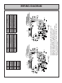
WIRING DIAGRAM.................................................................................................42
WARRANTY INFORMATION..................................................................................43
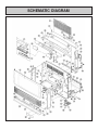
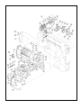
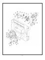
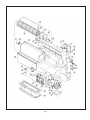
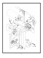
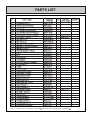
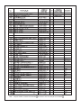
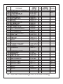
SCHEMATIC DIAGRAM/PARTS LIST ....................................................................45
RHFE-556 FLOW DIAGRAM..................................................................................55
EXTENDED FLUE PIPE KIT ..................................................................................57
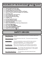
FEATURES OF THE RHFE-556FA /FTRA
◆
◆
◆
◆
◆
◆
◆
◆
◆
◆
◆
◆
◆
◆
◆
◆
◆
◆
◆
◆
UNITS
Clean Heating Forced Flue Type
Easy Operation One-Touch Ignition
Sensible Temperature Control Feature
Comfortable Room Temperature Control and Display
Warm Air Outlet at Floor Level (Keeps Your Feet Warm)
Child Safety Lock
Room Temperature Setting Memory
Dirty Air Filter Indicator Lamp
Energy-Saving Economy Setting
Humidifier Tray
Air Flow Directional Louvers
Direct Vent Easily Installed
Proportional Heating Variable Capacity
Hush! Quiet Operation
Modern Design Minimizes Floor Space Requirements
Failure Message Display
Dual Timers-556FTRA only
Timer Override Mode-556FTRA only
Pre-Heat Mode-556FTRA only
Remote Control-556FTRA only
SAFETY DEVICES
Spark Safety Device: Automatically shuts unit down when there is an abnormal spark at time
of ignition.
Flame Failure Device: Activated when burner flame fails. This prevents raw gas from being
released.
Overheat Switch:
This device automatically cuts the gas off if the heater exceeds a
predetermined temperature. This is normally caused by an
obstruction in front of the louvers, or a blocked fan filter.
Two Fusible Links:
Backs up the overheat switch. If the fusible link cuts the unit off, a
service call by an authorized person is required to replace the link.
Overcurrent Prevention Device:
This is a 3 amp. glass fuse found on P.C. board. Design
to shut unit down in case of overcurrent. If fuse blows all
indicator lamps will be "OFF".
Power Outage Safety Device:
This safety device cuts off gas passage and stops
operation.
–1–
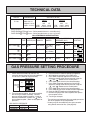
TECHNICAL DATA
WEIGHT
DIMENSIONS
51 Lbs.
Width: 29 1/2"
Height:21 13/16"
Depth: 9 13/16"
GAS RATE (BTU/h)
OUTPUT
INPUT
LOW
HIGH
NG
LP
8,200 8,200
21,500 20,700
LOW
HIGH
NG
LP
6,640 6,640
17,420 16,770
Burner Orifices:
RHFE-556FA /FTRA -P use: Orifice part #AU129-210×02-0.85(0.033")
RHFE-556FA /FTRA -N use: Orifice part #AU129-210×02-1.13(0.044")
GAS CONVERSION SPECIFICATIONS
MODEL
GAS DIAMETER OF PRIMARY
TYPE ORIFICE(mm) DAMPER
SECONDARY MANIFOLD DIFFERENTIAL DIP SWITCH
DAMPER
PRESSURE (W.C.)
POSITION
HI
LO
RHFE-556FA
LPG
0.85
556F-209-15 556F-208-5
( 2.5×15)
4.5"W.C.
0.8"W.C.
ON
OFF
RHFE-556FA
NG
1.13
556F-209-7 556F-208-7
(33×47hole)
3.8"W.C.
0.7"W.C.
ON
OFF
RHFE-556FTRA
LPG
0.85
556F-209-15 556F-208-5
4.5"W.C.
0.8"W.C.
ON
OFF
RHFE-556FTRA
NG
1.13
556F-209-7 556F-208-7
3.8"W.C.
0.7"W.C.
ON
OFF
GAS PRESSURE SETTING PROCEDURE
1. Check and ensure SW6 Dip Switches are
correct for the gas type for which the appliance
is to be used. (Refer to diagram below.)
SW6 DIP SWITCH
OFF
OFF OFF
OFF
NG
556FA
/
FTRA
1
2
3
4
ON
ON
OFF
OFF
1
2
3
4
LPG
2. There are two test points, one on the manifold,
one on the gas control assembly. Connect
pressure gauge to both test points. Using an
electronic manometer, connect the
side to
the manifold test point. (Refer to data plate for
pressure.)
GAS SUPPLY PRESSURE
NATURAL
5"W.C.
MINIMUM
10.5"W.C.
MAXIMUM
3. Press the ON/OFF button to operate the appliance.
4. With appliance operating, press SW5 once.
5. Press SW4 to operate appliance on forced low.
Adjust the setting to the correct pressure using the
"
" and "
" buttons on the control panel.
6. Press SW4 again to lock in the selected setting.
7. Press SW3 to operate appliance on forced high.
Adjust the setting to the correct pressure using the
"
" and "
" buttons on the control panel.
8. Press SW3 again to lock in the selected setting.
9. Press SW5 once to return heater to normal operation.
10. Press the ON/OFF button to turn the appliance off.
11. Remove the gauge from the test points and replace
the test point screws.
12. Test for gas escapes.
・The minimum and maximum inlet gas supply pressures
are for the purpose of input adjustment.
・Heaters may be converted from one gas to another
using Rinnai conversion kits. (See page 62)
PROPANE
8"W.C.
13"W.C.
–2–
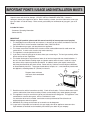
IMPORTANT POINTS / USAGE AND INSTALLATION MUSTS
Unpack heater and check for damage. (DO NOT INSTALL DAMAGED HEATER.) If heater is
damaged, contact your supplier for advise. Before installing a heater, check the label for the correct gas
type (see label on side of heater). Refer to local gas authority for confirmation of gas type if you are in
doubt.
Included in Carton:
・Customers Operating Information
・Conversion kits
IMPORTANT
Before using this product, please read this manual carefully to insure proper use of product.
1. The installation must conform with local codes or, in absence of local codes, the National Fuel Gas
Code, ANSI Z223.1 or the Canadian Installation Code, CAN/CGA-B149.
2. For information on gas type, see data plate on the appliance.
3. This heater must not be installed where curtains or other combustible materials could come into
contact with it. In some cases curtains may need restraining.
4. This appliance is not designed to be built in.
5. If you move, check the gas type in the area where you are moving to. The local gas authority will be
able to advise on local regulations.
6. This heater discharges a large volume of warm air at low level to provide even heat distribution. If
the air in the room contains cooking vapor or cigarette smoke, and the heater is used on a carpet,
the surface of the carpet may become discolored. In addition, some nylon carpets contain dyes
which may be affected by the warm air flow. Some soft vinyl surfaces are also subject to distortion,
or discoloration by warm air. To prevent discoloration of carpets, etc., a mat should be placed under
the appliance, extending about 30" (750mm) in front of it.
10"
0"
Diagram shows minimum
clearances from combustible
materials.
2"
2"
40"
7. Read these rules and the instructions carefully. Check all local codes. Failure to follow these could
cause a malfunction of the heater resulting in death, serious bodily injury and/or property damage.
8. This appliance is only for use with the type of gas indicated on the rating plate. This appliance is not
convertible for use with other gases, unless a certified kit is used.
If a conversion of the unit is needed, conversions must be performed at Rinnai America or
anthorized agent at owner's expense.
9. WARNING: Any change to this heater or its controls can be dangerous.
10.If a gas leak is suspected, turn heater off, turn gas supply valve off at appliance connector valve.
Open windows to ventilate area immediately and contact your dealer or gas company.
–3–
11 .DO NOT PLACE CLOTHING OR FLAMMABLE MATERIALS, GASOLINE AND OTHER
FLAMMABLE VAPORS AND LIQUIDS, ON OR NEAR THE HEATER.
12. YOUNG CHILDREN SHOULD BE CAREFULLY SUPERVISED WHEN THEY ARE IN THE SAME
ROOM WITH THE HEATER.
13. LPG containers must not be installed indoors.
14. Do not use this room heater if any part has been under water. Immediately call a qualified service
technician to inspect the room heater and to replace any part of the control system and any gas
control which has been under water.
15. Adequate clearances for accessibility for purposes of servicing and proper operation should be
provided.
16. Adequate clearances around air openings should be provided.
17. Do not install in areas where curtains, drapes, clothing, or other moving flammables are within 12
inches of this unit.
18. Periodic examination of the venting system is required.
19. The flow of combustion and ventilation air should not be obstructed.
20. A manufactured home (USA only) or mobile home OEM installation must conform with the
Manufactured Home Construction and Safety Standard, Title 24CFR, Part 3280, or, when such a
standard is not applicable, the Standard for Manufactured Home Installations, ANSI Z225.1 or
Standard for Gas Equipped Recreational Vehicles and Mobile Housing, CSA Z240.4.
21. "This appliance must be installed in accordance with the current standard CSA Z240.4 GAS
EQUIPPED RECREATIONAL VEHICLES AND MOBILE HOUSING. Cet appareil doit ette installe
conformement aux, exigences de la norme Z240.4 en vigeuer de l’ACNOR, Installations de gaz dans
les constructions mobiles et vehicules recreatifs."
22. If a blockage occurs at vent terminal due to snow, leaves or other type of obstruction the unit will
stop working. The unit will not function until blockage has been removed then if unit fails to operate,
contact a qualified service agency.
23. For a manufactured home (USA only) or mobile home OEM or residential or light commercial installation,this
unit has been designed and certified to be converted from natural gas to propane or vice-versa. When
provisions are being made to convert this unit, a certified conversion kit must be used. You must also
readjust manifold gas pressure to specifications indicated in the conversion manual. If in doubt, contact
Rinnai America for assistance.
GENERAL INFORMATION
THIS SERIES HEATER IS DESIGN CERTIFIED BY CSA
INTERNATIONAL AS A DIRECT VENT WALL FURNACE AND
MUST BE INSTALLED ACCORDING TO THESE INSTRUCTIONS.
ALTERATION OF THE ORIGINAL DESIGN INSTALLED OTHER
THAN AS SHOWN IN THESE INSTRUCTIONS OR USED WITH
A TYPE OF GAS NOT SHOWN ON THE RATING PLATE, IS
THE RESPONSIBILITY OF THE PERSON AND COMPANY
MAKING THE CHANGE.
・Rinnai is continually updating and improving products. Therefore, specifications are subject to
change without notice.
・Thank you for purchasing Rinnai forced flue gas heater.
・Please read the warranty thoroughly and keep it in a safe place.
–4–
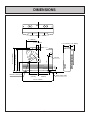
DIMENSIONS
11 " (280mm)
3 7/16" (88mm)
6 1/2" (165mm) 3 3/8" (85mm)
)
R1
(R27 1"
9mm
.0" m)
R8 6m
0
2
(R
18"
Gas Inlet
Exhaust at rear of unit
1"
(25mm)
8 7/16"(214mm)
19 15/16" (506mm)
21 13/16" (554mm)
3"
8 9/16"
(217mm)
9 5/8"
(245mm)
29 1/2" (750mm)
–5–
Power supply cable
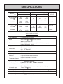
SPECIFICATIONS
BTU/h
MODEL
MIN. CLEARANCES
INPUT
OUTPUT
Low
8,200
Low
6,640
High
21,500
High
17,420
RHFE-556FA
/FTRA
Low
8,200
Low
6,640
PROPANE
High
20,700
High
16,770
RHFE-556FA
/FTRA
NATURAL
SIDE
TOP
FRONT
2"
(50mm)
10"
(250mm)
40"
(1m)
FAN CFM
OUTPUT
LO:110.5
HI:162.7
2"
(50mm)
LO:110.5
10"
(250mm)
40"
(1m)
HI:162.7
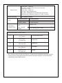
SPECIFICATIONS
Type of Appliance
Fan forced flued gas furnace
Model
RHFE-556FA /FTRA
Dimensions
Width (750mm) 29 1/2"
Depth (250mm with back spacer)9 13/16" (with back spacer)
Height (554mm) 21 13/16"
Weight
Approx. 51 lbs.
Connections
Electrical AC 120V 60Hz 52 watts
Gas 1/2" female NPT
Combustion System
Stainless steel bunsen burner
Ignition System
Continuous spark
Operation
Finger touch control buttons (non-lock)
Temperature Control
Electronic thermostat HI-LOW/OFF
Up/down switch
Temperature Range
Modulates Continuous
LOW 55°F 60°F 80°F HI High Combustion
Warm Air Outlet
Bottom front louver
Indicators/Lamps
Burner ON, child lock, filter, economy, temperature display,
Timers(FTRA Only)
Operating Buttons
On, Up/down, child-lock, economy/Timers, Override (FTRA
Economy Mode
Energy saving feature
Humidifier Tray
Capacity 3 pints (1300cc)
ENERGY SAVER
–6–
Only)
Safety Devices
Noise Level Range
TYPE
AIR SUPPLY/
EXHAUST PIPE
Flame failure – Flame rod
Over heat – Bi-metal switch, thermal fuse, thermistor
Power failure – PCB
Power surge – 3 Amp. fuse
Fan delay – Micro computer timer
Pre-purge – Combustion fan, pre-purge timer, spark sensor
Room over heat – Automatic cut off at 104°F after 10 minutes
HI
LOW
41
32dB(A)
Combustion Method
Forced combustion
Air Supply Exhaust
Closed Type
Radiation Method
Forced convection
Wall Penetration
Hole
(80mm) 3 1/8"
Max. Extended
Length
(4m, 2 bends)
13ft., 2 bends
SPECIFICATIONS FOR VENT SIZES
S
3" 4 1/2"
(75 115)mm
A
4 1/2" 9 1/2"
(115 240 )mm
Wood Walls
B
9 1/2" 15 3/4"
(240 400 )mm
Wood/Brick
C
15 3/4" 23 5/8"
(400 600 )mm
Brick/Block
D
23 5/8" 31 1/2"
(600 800 )mm
Special
Thin Walls Mobile Home
** BTU - Efficiency increases with vent Extension. Clearances from combustibles see pages 6 and 28.
** Thermal efficiency rating determined under continuous operating conditions, and was determined
independently of any installed system.
–7–
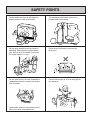
SAFETY POINTS
Do not restrict the warm air discharge by
placing articles in front of the heater.
This appliance must not be used for any
purpose other than heating.
Do not spray aerosols while the heater is
operating. Most aerosols contain butane
gas, and can be a fire hazard if used near
this heater when it is in use.
Do not install the heater in an unusually
dusty area.
Do not allow curtains or other flammable or
combustible materials to come into contact
with the heater.
Do not allow anyone to sit on or lean against
the appliance.
Combustible materials must not be placed
where the heater could ignite them.
–8–
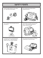
SAFETY POINTS
Keep flammable materials, trees, shrubs,
etc., away from the flue terminal.
Do not allow anyone to poke articles
through the louvers.
GAS
Gasoline
LPGAS
Filter should be cleaned at regular intervals.
See page 31.
Young children should be supervised at all
times. Hand or body contact with the
louvers should be avoided.
Clean as needed.
Do not place articles containing liquids on
top of the heater. Liquids spilled on the
controls may cause extensive damage.
Do not allow young children or an infant to
sleep directly in front of the heater.
–9–
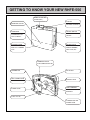
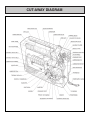
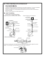
GETTING TO KNOW YOUR NEW RHFE-556
REMOTE CONTROL
(FTRA ONLY)
WARM AIR OUTLET
DISPLAY
TEMPERATURE
SETTING CONTROLS
HUMIDIFIER
REMOVE BOTTOM
COVER AND PULL
OUT TO REFILL
ON/OFF SWITCH
TURNS MAIN POWER
ON/OFF
BOTTOM COVER
HOLD BOTH SIDES
AND PULL TOWARD
YOU
RATING PLATE
MODEL NUMBER,
SERIAL NUMBER,
GAS TYPE, ETC.
TERMINAL BLOCK
FOR COMBUSTION FAN
THERMISTOR
AIR FILTER
GAS CONNECTIONS
1/2" NPT
EXHAUST PIPE
VENT TERMINAL
COMBUSTION/
EXHAUST
POWER CORD
PLUG 120V AC
COMBUSTION AIR
INTAKE HOSE
– 10 –
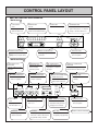
CONTROL PANEL LAYOUT
■ALL BUTTONS BEEP WHEN OPERATED.
<RHFE-556F >
CHILD SAFETY
TEMPERATURE
FILTER LAMP
OPERATION LAMP
LOCK
DISPLAY
Flashes when filter is dirty.
This lamp turns
Lamp is "green"
Set temperature lamp stays on.
"green" when power is on. Lamp will
when this feature is on.
Current room temperature flashes.
change to "red" when burner is on.
LO 60 64 68 72 76 80 HI
Filter
Economy
Child Lock
ON
Temperature
Control
TEMPERATURE BUTTONS
ON/OFF
ENERGY SAVING BUTTON
ON/OFF BUTTON
adjust temp. to lower setting.
Lamp is green when this feature
Easy operation
adjust temp. to higher setting.
is activated.
One touch ignition
<RHFE-556FTRA
>
CHILD PROOF LOCK
TIMER INDICATOR
TIME / TEMP DISPLAY
POWER ON / COMBUSTION
INDICATOR
Indicates that Timer 1 or
Shows either the time of day,
INDICATOR
Indicates Child Proof lock is
Timer 2 has been
temperatures, or code error
Indicates that the appliance is turned
activated.
selected to operate.
messages.
ON and whether the burner is alight.
ECONOMY INDICATOR
OVERRIDE INDICATOR
CLOCK ADJUSTMENT AND
FILTER LAMP
Indicates that the Economy
Indicates that the override
TIMER INDICATORS
Indicates that the filter needs
mode is in operation.
function is activated.
Indicates that clock or dual
cleaning.
timer program is being set.
Child Lock Economy Timer 1
Timer 2 Override
Clock
AM
PM
Timer 1
Timer 2
Set Room
Temp
・
Time
on
off
Set times
Filter
ON
ON / OFF
CHILD SAFETY
ON / OFF TIMER
TIME / TEMP ADJUSTMENT
ON/OFF BUTTON
LOCK
Selects operating mode for
Increases or decreases the
Easy operation
Lamp is "green"
Timer 1 or 2.
temperature setting as well as
One touch ignition
changing hours or minutes.
when this feature is on.
ECONOMY
OVERRIDE
SET TIMES
Lamp is green when this
Temporarily changes operation from
Selects clock and / or timers
feature is activated.
ON to OFF or OFF to ON, until next
for adjusting or programming.
programmed setting is reached.
– 11 –
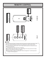
REMOTE CONTROL RECEIVER
REVERSE
BATTERY
R2032
C
FRONT
Increases or decreases
the temperature setting.
TEMPERATURE
ADJUSTMENT
Stops heater manually.
OFF
ON
Operates the heater
manually.
OFF BUTTON
OPEN
Simply open the back of the remote
control and replace Lithium battery.
TYPE: CR2032
TO REPLACE BATTERY
ON BUTTON
Power source
for operating
remote control.
REMOTE CONTROL
■ NOTE
Some fluorescent lights may interfere with the transmission of remote control signals, in this
case changing the position from which you are operating the remote control may help.
Avoid leaving the remote control in direct sunlight and do not place the remote close to the
louvers of the heater.
Avoid getting the remote control wet, or dropping it.
The remote control works within 16 feet and an angle of 20° to the receiver on the heater.
Only use the battery type specified. (CR2032).
Remove battery if control is not going to be used for a long period. This will help to avoid
damage from leaking batteries.
– 12 –
CUT-AWAY DIAGRAM
– 13 –
NOTICE BEFORE INSTALLATION
The heater must be installed by a qualified service
person according to this installation instruction.
The appliance, when installed, must be electrically
grounded in accordance with local codes or, in the
absence of local codes, with the National Electrical
Code, ANSI/NFPA 70 or Canadian Electrical Code,
CSA C22.1, if an external electrical source is utilized.
Check your local building codes for the proper method
of installation. In the case of absence of local codes,
this heater should be installed in accordance with the
National Fuel Gas Code ANSI Z223 1.
WARNING: THIS APPLIANCE IS EQUIPPED
WITH A THREE PRONG (GROUNDING) PLUG
FOR YOUR PROTECTION AGAINST SHOCK
HAZARD AND SHOULD BE PLUGGED DIRECTLY
INTO A PROPERLY GROUNDED THREE PRONG
RECEPTACLE. Do not cut or remove the grounding
prong from the plug.
Check local codes or, in the absence of local codes,
the current CAN/CGA B149 INSTALLATION
CODE.
DUE TO HIGH TEMPERATURES, THE
APPLIANCE SHOULD BE LOCATED OUT OF
TRAFFIC AND AWAY FROM FURNITURE AND
DRAPERIES.
CHILDREN AND ADULTS SHOULD BE ALERTED
TO THE HAZARDS OF HIGH SURFACE
TEMPERATURES AND SHOULD STAY AWAY TO
AVOID BURNS OR CLOTHING IGNITION.
This gas appliance must not be connected to a
chimney flue serving a separate solid-fuel burning
appliance.
When the appliance is installed directly on carpeting,
tile or other combustible material other than wood
flooring, the appliance shall be installed on a metal or
wood panel extending the full width and depth of the
appliance.
“WARNING” Do not operate appliance with the
panel(s) removed, cracked or broken. Replacement
of the panel(s) should be done by a licensed or
qualified service person.
Rinnai recommends a dedicated electrical circuit.
Appliance input ratings are based on sea level
operation and need not be changed for operation up
to 2,000 feet elevation. For operation at elevations
above 2,000 feet, manufactured to specified deration
conditions for Canada and the United States.
INSTALLATION AND REPAIR SHOULD BE DONE
BY A QUALIFIED SERVICE PERSON. THE
APPLIANCE SHOULD BE INSPECTED BEFORE
USE AND AT LEAST ANNUALLY BY A QUALIFIED
SERVICE PERSON. MORE FREQUENT
CLEANING MAY BE REQUIRED DUE TO
EXCESSIVE LINT FROM CARPETING, BEDDING
MATERIAL, ETC. IT IS IMPERATIVE THAT
CONTROL COMPARTMENTS, BURNERS AND
CIRCULATING AIR PASSAGEWAYS OF THE UNIT
BE KEPT CLEAN.
– 14 –
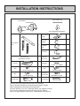
INSTALLATION INSTRUCTIONS
Flue Manifold
Spare rubber seal
1
(‘A’ Flue units only)
1
(For weatherboard installations)
Back Spacer
Set
Flue Locking
Clamp
1
Flue Lock
Stopper
1
Insulation
Clip
1
Hose Clip
2
1
Plastic tie
for air inlet
1
1
(M4 20)
1
Customers operating
information and
Installation Instructions
Air Filter
1
For Flue Lock Stopper
(M4)
6
(M4)
3
For Back Spacer Set
(M4)
For Flue Manifold
2
For Air Intake Clip
Wall Bracket
1
(M4.8 32)
Wood Screws
5
Wall Bracket Screws
Spacer Bracket
Check to ensure gas supply matches that of the appliance.
Refer to local gas authority for confirmation of gas type if in doubt.
Refer to data plate located inside of the front panel.
Check for damage, if the unit is damaged contact your supplier or Rinnai.
Do not install a damaged unit before checking with your supplier.
Refer to an approved pipe sizing chart if in doubt about size of gas line.
– 15 –
1
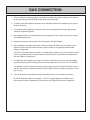
GAS CONNECTION
1. The gas supply line shall be gas tight, sized and so installed as to provide a supply of gas sufficient
to meet the maximum demand of the heater without loss of pressure.
2. A shut off valve (and appliance connector valve) should be installed in the upstream of the gas line
to permit servicing.
3. Flexible pipe and any appliance connector valve used for gas piping shall be types approved by
nationally recognized agencies.
4. Any compound used on the threaded joint of the gas piping shall be a type which resists the action
of liquefied petroleum gas.
5. Supplied gas pressure must be within the limits shown in the specifications.
6. After completion of gas pipe connections, all joints including the heater must be checked for gas
tightness by means of leak detector solution, soap and water, or an equivalent nonflammable
solution, as applicable.
CAUTION: Since some leak test solutions, including soap and water, may cause corrosion or stress
cracking, the piping shall be rinsed with water after testing, unless it has been determined that the
leak test solution is noncorrosive.
7. The appliance and its appliance main gas valve must be disconnected from the gas supply piping
system during any pressure testing of that system at test pressures in excess of 1/2 P.S.I (3.5kPa).
The appliance must be isolated from the gas supply piping system by closing its individual manual
shut off valve during any pressure testing of the gas supply system at test pressures equal to or less
than 1/2 psig.
8. Two 1/8" test plugs are provided for testing of manifold pressure see schematic for location.
At time of installation installer must supply a 1/8" N.P.T. plugged tapping, accessible for test
manometer connection, immediately up stream of the gas supply connection to the appliance.
– 16 –
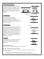
VENT LOCATION
FITTING TOP SPACER + WALL CLIP
FLUE MANIFOLD POSITION
Tighten all screws.
Center of hole for flue manifold can be drilled
anywhere within the shaded area. (To avoid studs,
etc.)
Top spacer
FOR WEATHERBOARD WALLS DRILL THROUGH
CENTER OF WEATHER BOARD FROM OUTSIDE,
THEN DRILL FROM INSIDE THROUGH PLASTERBOARD.
Cavity Opening
11"
(280mm)
Spacer bracket
8 7/16"
(214mm)
R
(R2 11"
79m
m)
SECURE HEATER TO WALL
3 1/8"
(80mm)
Flue Hole
Top spacer
.0" )
R8 6mm
0
2
(R
Spacer bracket
8 9/16"
(217mm)
Wall bracket
Before drilling the flue hole, check for water and gas
pipes as well as electric cables. Use a 3 1/8"
(80mm) drill for hole through wall.
WALL MOUNTING BRACKETS
Replace top spacer, clipping the spacer into the wall
brackets at the same time as attaching it to the
heater. Secure top spacer with the screws provided.
THE HEATER IS NOW SECURED TO THE WALL.
Place top back spacer in position. Mark the position
of the top edge of the top space on the wall. Move
the heater away from the wall. Mark center lines 1
1/8" (30mm) down from the top edge mark, and 1
9/16" (40mm) in front the left and right hand sides of
the top spacer. Attach wall brackets at the marked
position.
Spacer
Replace fan filter.
– 17 –
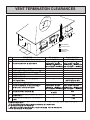
VENT TERMINATION CLEARANCES
INSIDE
CORNER DETAIL
G
H
A
I
B
D
M
FIXED
CLOSED
B
K
OPERABLE
E
B
C
J
FIXED
CLOSED
B
B
A
OPERABLE
L
V
VENT TERMINAL
X
AIR SUPPLY INLET
F
AREA WHERE
TERMINAL IS NOT
PERMITTED
B
REF
A
U.S. Installations
DESCRIPTION
1 foot
1 foot
Clearance above grade, veranda, porch, deck, or balcony
** 6 inches for appliances
B
Clearance to window or door that may be opened
Canadian Installations
10,000
Btuh, 9 inches for appliances
10,000 Btuh and
>
50,000 Btuh, 12
inches for appliances
>50,000 Btuh
6 inches for appliances
10,000 Btuh and
inches for appliances
C
Clearance to permanently closed window
*
*
Vertical clearance to ventilated to soffit, eaves, or overhang
*
*
E
Clearance to unventilated soffit , eaves, or overhang
*
*
F
Clearance to outside corner
*
*
G
Clearance to inside corner
*
H
I
*
the meter/regulator assembly
*
Clearance to service regulator vent outlet
3 feet
** 6 inches for appliances
J
Clearance to nonmechanical air supply inlet to building or
the combustion air inlet to any other appliance
L
M
Clearance to a forced air inlet into a building
>
50,000 Btuh, 12
inches for appliances
K
10,000
Btuh, 9 inches for appliances
10,000 Btuh and
>50,000 Btuh
3 feet above if within 10 feet
horizontally
Clearance above paved sidewalk or paved driveway located
on public property
Clearance under deck, veranda, porch, or balcony (open on
3 sides)
>100,000 Btuh
3 feet within a height 15 feet above
*
meter/regulator assembly
6 inches for appliances
10,000 Btuh and
inches for appliances
>100,000 Btuh
6 feet
†7 feet
*
‡1 foot
†A vent shall not terminate directly above a sidewalk or paved driveway that is located between
two single family dwellings and serves both dwellings.
Permanent only if veranda, porch, deck, or balcony is fully open on a minimum of two sides beneath the floor.
** 4 feet for units other than Direct-Vent Appliance.
– 18 –
>
100,000 Btuh, 36
*
requirement of the gas supplier.
10,000
Btuh, 12 inches for appliances
* For clearances not specified in ANSI Z223.1 / NFPA 54 or CAN/CGA-B149, use clearances in accordance with local installation codes and the
‡
>
100,000 Btuh, 36
D
Clearance to each side of center line extended above
10,000
Btuh, 12 inches for appliances
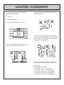
LOCATION / CLEARANCES
When positioning the heater the main points
governing the location are:
The flue terminal should be positioned away from
flammable materials.
1. Flueing
2. Warm air distribution
This heater is not designed to be build in.
LP GAS
Flue Terminal
Do not flue into natural draught flues or fireplaces,
this unit can only be used with one of the five types
of Rinnai flue kits. Do not flue unit into other rooms.
Flue terminal must be outside.
The flue is not designed to be positioned under
floors, or below the level of the heater.
Flue
Terminal
Flue
Terminal
Flue may be positioned directly under opening
windows, with a minimum clearance of 9" (230mm).
FLUE SIZES:
5 Flue lengths are available.
S flue walls 3" 4 1/2" (75 115mm)
A flue walls 4 1/2" 9 1/2" (115 240mm)
B flue walls 9 1/2" 15 3/4" (240 400mm)
C flue walls 15 3/4" 23 5/8" (400 600mm)
D flue walls 23 5/8" 31 1/2" (600 800mm)
– 19 –
SNOW AREAS
FIT BACK COVERS (SIDES ONLY)
Fit back covers (sides only) as shown below.
Engage Lugs
Snow
Secure With
Screws
In areas subject to heavy snowfall, keep snow clear
of flue terminal at all times.
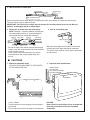
STANDARD INSTALLATION OF FLUE MANIFOLD.
Diagram below shows minimum clearances and
distances from obstructions.
Also check local regulations.
Clearance in accordance with local installation
codes and the requirements of the gas supplier.
Wall
Non
Flammable
10"(250mm)
24"
(600mm)
(600mm)24"
Flammable
20"(500mm)
Opposite
Wall
Floor
Side Clearances
20"
(500mm)
Obstruction
– 20 –
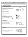
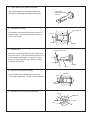
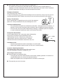
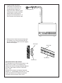
SLEEVE AND MANIFOLD INSTALLATION
METHOD FOR STANDARD WALLS
1. Disassemble Manifold from Sleeve.
Flanges
The flue consists of 3 parts, sleeve, inside connectors
and tube, outside terminal; (dis-assembly by pulling
hard on outside terminal and inner connections, then
pull sleeve off outer terminal.)
NOTE: Clearance to combustibles for terminal
assembly sleeve and flanges is 0".
Sleeve
Connection
Terminal
2. Adjustment of Sleeve Length.
Measure wall thickness through previously drilled
3 1/8 (80mm) hole.
End of sleeve should protrude 3/16" 3/8" (5 10mm)
from outside wall. Adjust sleeve length to wall
thickness plus 3/16" 3/8" (5 10mm). (Sleeve is
threaded for adjustment.) Do not extend beyond red
line.
Do not extend
beyond red line
Extension joint
under plastic
Extension
("S" and "A" flues only)
Adjust length by turning sleeve.
3. For S and A flue only.
Depending on flue set and wall thickness extension
piece “C” may need to be removed.
Cut plastic, remove extension, then follow instruction 2.
This applies to “S” and “A” flues only.
There is no extension on other flues, they can be fully
adjusted by turning the threaded section.
A
B
"A" Flue only
C
Remove extension at this
point it necessary.
4. Fixing Sleeve.
5-10mm
Fix to the wall, using the 3 screws provided.
NOTE: The flange is marked “TOP”, sleeve must be
fitted with this mark Up. Check sleeve protrudes 3/16"
3/8" (5 10mm) on the outside.
2°
"TOP"
Fixing Screw
Don't remove green plastic covering from sleeve.
– 21 –
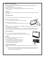
5. Check rubber seal is in place on terminal.
Terminal seal
(Add "weather board"
seal here)
*For weather board walls, add spare rubber seal
provided to compensate for weather board angle.
6. Installation of Terminal
"TOP" mark "A"
From outside, insert terminal into sleeve with the “A”
mark at the top. Left hand side fixing tie is marked
“LEFT” (from inside).
Label
Fixing tie
Terminal
7. Attached Ties
Cut (leave 20mm free)
Pull hard on left and right hand side ties, clip ties over
lugs inside sleeve. You should be able to pull ties 2 or
3 slots past the starting point. Cut the ties, leaving
about 3/4" (20mm) past the lugs. Bend ties so they
are parallel with the wall.
Pull hard
Fixing tie
Terminal
Lug
Sleeve
8. Insert Inner Connection Assembly.
Top Mark
Push assembly into the terminal tube, make sure
“TOP” mark is uppermost. Fix with 3 screws provided.
Screw
lnner
Connections
9. Manifold can still be turned after attaching.
Outlet
20˚
Rubber cap
Inlet
– 22 –
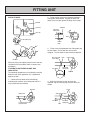
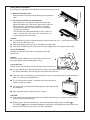
FITTING UNIT
AIR INLET HOSE
2. Fit the locking clamp over connection between
sliding tube and manifold. Engage the hook and
rotate it until it snaps against the body of the clamp.
Manifold
Manifold
Inlet hose
Flue outlet
Sliding tube
Hose clip
Hook
Detail of Hose clip
Locking
Clamp
Locking
clamp
Plastic tie
3. Fit the screw clamp between the sliding tube and
the flue elbow. Secure with the 4mm screws
supplied. The flue outlet is now locked into position.
Inlet elbow
Flue Outlet tube screw
screw clamp
Locking clamp
Inlet hose
When servicing unit replace plastic tie with new one.
(Available at local hardware store or contact local
distributor.)
Flue Outlet
sliding tube
Flue elbow
LOCKING CLAMP SCREW CLAMP AND
INSULATION.
The following components can be fitted by reaching
down the rear of the appliance as it is positioned
against the wall.
Manifold
1. Connect the flue outlet to the manifold by
extending the stainless steel sliding tube until it is
fully inserted into the manifold.
4. Slide the insulation sleeve up to the flue
manifold, slip the securing clip over the sleeve as
shown.
Fit clip
Manifold
Slide insulation sock
Sliding Tube
Slide
Flue elbow
Do not extend flue tube
beyond red line.
Sock
– 23 –
Flue outlet
Sliding tube
Slide to here
Levelling screws(Adjustable legs)
Up to 10 mm
Adjustable Leg
If necessary, the unit can be levelled using the
adjustable legs under the front right and left hand
side legs.
INSTRUCT CUSTOMER ON USE OF HEATER
When you are satisfied that the appliance is
operating correctly, explain operation of heater to
the customer.
Fault-Failure Procedure
If unable to get the heater to operating correctly,
contact Rinnai directly or your Agent or Gas Utility.
Do not use electrical extension cords to connect unit
to power supply. Keep the power cord away from
the flue.
Some items are not covered under the unit's
warranty. Example: annual maintenance, carbon on
flame rods/ignitor, dust, spider webs, etc.
– 24 –
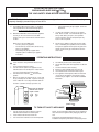
OPERATING INSTRUCTION LABEL
ENERGYSAVER RHFE-556FA /FTRA
FOR YOUR SAFETY READ BEFORE OPERATING
WARNING: If you do not follow these instructions exactly, a fire or explosion may result causing
property damage, personal injury or loss of life.
A.
This appliance does not have a pilot. It is equipped
with an ignition device which automatically lights the
burner. Do not try to light the burner by hand.
B.
BEFORE OPERATING smell all around the appliance
area for gas. Be sure to smell next to the floor
because some gas is heavier than air and will settle on
the floor.
•
WHAT TO DO IF YOU SMELL GAS
•
Do not try to light any appliance.
•
Do not touch any electric switch; do not use any
phone in your building.
•
Immediately call your gas supplier from a
neighbor's phone. Follow the gas supplier's
instructions.
If you cannot reach your gas supplier, call the fire
department.
C.
Use only your hand push in or turn the gas control
knob. Never use tools. If the knob will not push in or
turn by hand, don't try to repair it, call a qualified
service technician. Force or attempted repair may
result in a fire or explosion.
D.
Do not use this appliance if any part has been under
water. Immediately call a qualified service technician
to inspect the appliance and to replace any part of the
control system and any gas control which has been
under water.
OPERATING INSTRUCTIONS
1.
2.
3.
4.
5.
6.
Turn Manual gas valve to the full on position.
Turn on all electric power to the appliance via ON/OFF
button.
7. Set the thermostat to desired setting.
8. Burner is lit when indicator lamp “ON” turns red.
9. “ON” indicator flashes when burner fails to ignite.
10. If the appliance will not operate, follow the instruction
“TO turn off gas to appliance” and call your service
technician or gas supplier. See manual for additional
information.
STOP! Read the safety information above on this
label.
Set the thermostat to lowest setting.
Turn off all electric power to the appliance via the
ON/OFF button on the control panel. Locate manual
gas valve to be found on back side of heater.
Turn Manual valve clockwise
to the full OFF
position.
Wait five (5) minutes to clear out any gas. Then smell
for gas, including near the floor. If you then smell gas,
STOP! Follow “B” in the safety information above on
this label. If you don't smell gas go to next step.
TIMER/CLOCK SET INDICATOR
ON-OFF SWITCH INDICATOR
DIGITAL DISPLAY
BACK SIDE OF HEATER
MANUAL GAS VALVE
OPEN CLOSED
ON-OFF SWITCH
TIMER/TENP ADJUSTMENT
TIMER/CLOCK SET
(556FTRA
)
TO TURN OFF GAS TO APPLIANCE
1.
2.
3.
Turn off electric power to the appliance using the
ON/OFF button located on the control panel.
Locate manual valve on back side of unit.
Turn manual valve clockwise to the full OFF position.
NOTE: The fan will continue to operate until the appliance is
cool, do not turn the appliance off by unplugging it from the
wall.
Keep burner and control compartment clean. See
installation and operating instructions accompanying heater.
– 25 –
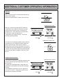
ADDITIONAL CUSTOMER OPERATING INFORMATION
IGNITION
Make certain the heater is connected into both the gas
and the electric power.
Depress the ignition ON/OFF button slowly and firmly.
Filter
ON
ON/OFF
TEMPERATURE LEVEL
When you release the ignition ON/OFF button the
‘Temperature Level’ lamps will illuminate, the spark
will ignite the main burner and the convection fan
will begin to run. If the heater does not ignite within
15 seconds the spark will stop and the
‘Temperature Level’ lamps will flash. Turn off unit
and repeat ignition operation.
LO 60 64 68 72 76 80 HI
AM
PM
Set ・ Room
Temp
・
Time
Temperature
Control
〈556FA 〉
〈556FTRA
〉
COMBUSTION INDICATOR
This heater has an automatic ignition system, when the
main burner has lit, the ignition on lamp will glow red,
and the spark will stop. There may be a smell of
burning dust or oil the first time the heater is lit or when
the heater has been out of operation for a long time, this
is normal.You may need to repeat the ignition operation
the first time the heater is plugged in, due to air in the
gas line.
Filter
ON
ON/OFF
TEMPERATURE CONTROL
The thermostat automatically modulates the burner and
the fan to maintain the room temperature which you
have selected.
To change the room temperature, simply adjust the
temperature control buttons until the desired setting is
indicated.
The temperature range from LO to HI is about 54°F
(12°C) to 97°F (36°C). Temperature control may be
affected by the location of the heater.
TEMPERATURE CONTROL
LO 60 64 68 72 76 80 HI
Set ・ Room
Temperature
Control
〈556FA 〉
– 26 –
AM
PM
Temp
・
Time
〈556FTRA
〉
ROOM TEMPERATURE DISPLAY
TEMPERATURE LEVEL
Temperature is indicated by the digital read out above
the temperature/time adjustment buttons. The room
temperature is indicated by the digital display above
room. The set temperature is indicated by the digital
display above set. You will notice the fan speed
changing as the heater modulates to match the room
temperature.
LO 60 64 68 72 76 80 HI
AM
PM
Set ・ Room
Temp
・
Time
Temperature
Control
〈556FA 〉
TO TURN UNIT OFF
〈556FTRA
IGNITION BUTTON
Depress ignition ON/OFF button again.
The switch will return to the off position.
Do not turn off unplugging at the power outlet.
Convection fan continues to run until heater is cool. The
convection fan may start again after a few minutes to
remove any residual heat.
Filter
ON
ON/OFF
ECONOMY BUTTON
ECONOMY
To select ‘Economy Mode’, push the ‘Economy’ button,
the green lamp will glow. 30 minutes after the room
temperature reaches the preset temperature (set by the
thermostat), the ‘Economy Mode’, if set, reduces the
temperature by 2°F, after another 30 minutes it reduces
the temperature by a further 2°F, this is an energy
saving feature. When the heater is running in lowest
position on the thermostat, the ‘Economy Mode’ does
not operate. It does not operate if the heater is under
capacity for the room size.
Economy
FILTER LAMP
If the filter lamp glows during operation, check air filter
for dust. If there is dust present, clean filter. See
section on care of heater. Turn heater off before
cleaning filters.
Filter
ON
ON/OFF
OPERATING PRECAUTIONS
Please read this section carefully, before using your Forced flue heater.
Gas Type, Power Source, and Manufactured Date
■ Type of gas, power source and manufactured date are displayed on the nameplate placed on the
right side of the unit.
•
•
Do not use gas other than the type of gas (gas group) indicated on the nameplate.
This equipment is for 120 V AC (60Hz) only. Do not use power source other than what is listed.
– 27 –
〉
Caution
● Should the type of gas or power source be different, please contact your dealer. Using a different
type of gas or power source may affect the performance or may be dangerous.
● If you are moving to another area, please check the types of gas and power source provided in the
area. If the types of gas and power source are different, adjustment or modification is necessary.
Please consult the gas provider in the new area.
Usage
■ Do not use for drying clothes!
Do not use for any other purposes other than heating
(e.g., drying the laundry).
Draping clothes over the unit blocks the warm air outlet or the filter area and is very dangerous,
as it causes heat to build up inside the unit.
Usage Location
■ Do not use near flammable material ! ! !
Place the unit sufficiently away from flammable objects such as furniture, wall and curtains. Check
carefully when installing the unit.
REQUIRED DISTANCE FROM FLAMMABLES:
Top:
At least 250mm or (10")
Left:
At least 50mm or (2")
Front: At least 1m or (40")
10"
0"
Right: At least 50mm or (2")
2"
2"
40"
■ Watch for falling objects ! ! !
Do not place under a shelf or in other locations where there is a danger of an object falling on the unit.
■ Avoid using in special purpose rooms ! ! !
This equipment is made for use as a heater for a residential building. Do not use in beauty salons,
factories and other places where spray or chemicals are used or where a large amount of dust is
present.
Do not use hair treatment products containing silicon in a room heated by the Forced Flue heater, as
they may cause ignition error, flame extinction or other malfunctions.
– 28 –
■ Insert a board under the unit when placing on carpeted floor ! ! !
This heater may be installed on combustible flooring. When the heater is installed directly on
carpeting, tile or other combustible material other than wood flooring, the heater shall be installed on
a metal or wood panel extending the full width and depth of the heater.
Emergency Procedures:
Stay calm and turn the unit off ! ! !
In case of an emergency (e.g., abnormal overheating of the unit, loud noise), always stay calm, turn the
unit off by pushing the ON/OFF button, close the gas valve and contact your dealer or gas supplier.
During a Thunderstorm
When a thunderstorm is approaching, turn the unit off and unplug the
power cord. Heavy thunderstorm may cause damage to the unit.
Inspection and Maintenance
• Be sure to perform inspection and maintenance procedures. (See page 30 and 41 for details.) In
particular, check the gas connection, power connection and air supply/exhaust pipe connection.
• Do not use the unit if you suspect malfunctioning or damage. Incomplete repairs are dangerous.
In case of malfunction contact your dealer or the nearest Rinnai office.
During Snow Accumulation
If the air supply/exhaust vent is covered by snow or damaged by
falling icicles, the exhaust may be blocked and cause
malfunctioning of the unit. Keep the area around the air
supply/exhaust vent free of snow and icicles. Minimum
clearance from snow accumulations should be at least (24").
snow
24"
Installation of Unit:
• Please ask your dealer to install the unit properly in a safe location:
• Refer to the installation manual to make sure the unit is installed properly.
Customer's Operating Information
The following pages explain how to use the Forced flue heater.
Also read “Operating Precautions” on pages 26 36.
When Using for the First Time
■ Check the power cord and power plug.
• Firmly plug the unit into an electrical outlet, ensure outlet is properly grounded. An outlet that is
not grounded properly can cause unit to operate erratically.
• Make sure the power cord is not exposed to the heat from the exhaust pipe.
■ Fully open the gas valve in the room.
– 29 –
Before the Cold Season Begins
■ Check the air supply/exhaust connection.
● Before using this heater, inspect the air supply/exhaust connection to make sure the pipe is not
disconnected or bent.
■ Check the main unit and the air supply/exhaust.
● Make sure there is no combustible or flammable material near the main unit or the air
supply/exhaust.
CAUTION:
If you find a problem with the air supply/exhaust do not use the unit. Contact your dealer or the nearest
Rinnai office.
CHILD SAFETY LOCK
The child safety lock feature prevents accidents due to tampering by small children.
■ Press the “Child Safety Lock” button.
The “Child Safety Lock” lamp comes on and the lock engages.
■ Cancelling the child safety lock.
Press the child safety lock button again and hold for two (1) seconds.
Note:
If the child safety lock is engaged while the unit is operating, all operations by switches and buttons will
be disabled except turning the unit off.
If the child safety lock is engaged while the unit is off, all operation will be disabled. When you turn the
unit on and the child safety lock is engaged you must cancel the child safety lock before preceding.
AIR FLOW CONTROL:
■ The direction of air flow may be changed to the left or right.
Use a screwdriver or a similar object to change the direction of the vertical
louver.
CAUTION:
● Do not adjust repeatedly (more than 5 6 times), as it
may cause the louver to break.
● The horizontal louver (which determines the vertical
air flow direction) is fixed and cannot be adjusted.
● Do not adjust the air flow direction while warm air is
flowing, as it may cause burn injury.
Sensible Temperature Control:
The sensible temperature control feature enables comfortable heating which matches the conditions in
the room.
• Based on the information collected by the room temperature thermistor when the heating starts,
the heating capacity is automatically adjusted to achieve a comfortable heating effect and to
reach the set room temperature quickly.
– 30 –
Adding Water to Humidifier:
If the air gets dry, add water to the humidifier tray to add moisture to the air.
1) Remove the bottom cover.
Hold both ends of the cover and pull toward you to remove the
cover.
2) Pull out the humidifier tray and add water.
After adding water, gently push the plate back inside and
replace the bottom cover. Be careful not to spill the water, as
spilled water may cause staining, corrosion, or damage.
*If the humidifier capacity is not sufficient, use a humidifier
available on the market.
*The humidifier tray holds approximately 3 pints (1300cc) of
water. The time water lasts varies from 10 to 15 hours, so
check the water level occasionally.
Caution:
● The humidifier tray and the surrounding area are hot when the unit is on. To avoid burns, do not add
water to the tray while unit is on.
● Avoid adding water when the room is susceptible to condensation.
● If the water overflows from the water level hole when adding water, do not add any more water.
Care of Unit Exterior:
Dampen soft cloth with warm water, wring water out well and
wipe the unit.
Caution:
Never use volatile substances such as benzine or thinners, as
they cause fading of paint or deformation of resin.
Care of Air Filter:
Always clean the air filter when the filter indicator lamp starts blinking.
■ The filter indicator lamp starts blinking when the dust accumulates on the air filter. In this event, turn
the unit off immediately, wait until the unit cools off and clean the filter.
■ Even if the lamp is not blinking, if you think the filter is dirty, clean the filter while you are cleaning the
room. This will ensure comfortable use.
■ The air filter may be removed. Clean both sides of the filter with a
vacuum cleaner or a duster.
■ If the filter is greasy, wash quickly with detergent, shake water off and
dry completely.
■ After cleaning and drying, replace the filter securely.
CAUTION:
● If you continue to use the heater with the filter indicator lamp flashing, the sensor may detect trouble
and turn the unit off automatically.
● When the unit is turned off automatically, the room temperature display lamp "68"(556FA ) /
"14"(556FTRA ) and the "operation/combustion" lamp flashes, indicating that the safety device has
been activated. In this event, clean the air filter immediately.
– 31 –
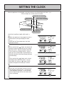
SETTING THE CLOCK
When the appliance is first plugged in and then turned on, the Digital Display will show
As an example, let's set the clock to 10:35 am.
.
TIMER/CLOCK SET INDICATOR
ON-OFF SWITCH INDICATOR
DIGITAL DISPLAY
ON-OFF SWITCH
TIMER/TENP ADJUSTMENT
TIMER/CLOCK SET
OPEN THE CONTROL PANEL-SEE PAGE 11.
When the appliance is first plugged in or after a
power failure, the Digital Display will show
.
Press the Set Times button once, the Clock
Indicator will flash.
Press and hold the “
” button; the minutes will
begin to change first, then the time will change
by whole hours. Release the button when AM
10:00 shows on the Digital Display. Confirm
that you have selected AM, a small indicator on
the left hand side of the Digital Display indicates
the AM setting.
Press and hold the “
” button again, release
the button when AM 10:35 shows. If you go
past AM 10:35, then the “
” button can be
used to change the time settings in reverse.
Press the Times Set button five times to lock in
and complete setting the time. The Clock and
Timer indicators will go out. A small indicator
on the Digital Display will flash to show that the
clock is operating.
– 32 –
Clock
AM
PM
Timer 1
Set Room
Temp
・
Time
Timer 2
on
off
on
off
on
off
on
off
Set times
Clock
AM
PM
Timer 1
Set Room
Temp
・
Time
Timer 2
Set times
Clock
AM
PM
Timer 1
Set Room
Temp
・
Time
Timer 2
Set times
Clock
AM
PM
Timer 1
Set Room
Temp
・
Time
Timer 2
Set times
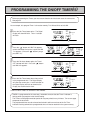
PROGRAMMING THE ON/OFF TIMER(S)
Before programming the Timers you must ensure that the clock has been set to the correct time.
See page 32.
As an example, let's program Timer 1 to heat the room by 7:10 AM and finish at 9:00 AM.
Press the Set Times button twice. The Digital
Display will show AM 6:00. Timer 1 indicator
will flash.
Press the “
” button until AM 7:00 appears,
release the button, then press it again until AM
7:10 appears. (Press the “
” button if you go
past AM 7:10.)
Press the Set times button again, the Timer 1
OFF indicator will flash. Press the “
” button
until AM 9:00 appears.
Clock
AM
PM
Timer 1
Temp
・
Time
off
Set times
Clock
AM
PM
Timer 1
Timer 2
Set Room
on
off
imer 2 Override
Temp
・
Time
Set times
Filte
Clock
AM
PM
Timer 1
Timer 2
Room
ON /Set
Temp
・
Time
Set times
Clock
AM
PM
Timer 1
Set Room
Temp
・
Time
Press the Set Times button three times to lock
in the programmed time. The Digital Display
will show the current time. A small indicator on
the Digital Display will flash to show that the
Display has returned to the clock.
on
Timer 2
Set Room
Timer 2
on
off
on
off
Set times
Clock
AM
PM
Timer 1
Set Room
Temp
・
Time
Timer 2
Set times
TURN TO NEXT PAGE TO OPERATE THE TIMERS.
TIMER 2 is programmed in the same way, remember to ensure that the Timer 2 indicator is
flashing when you program in the desired setting.
The Timers can be programmed to operate for any two periods in any 24 hours. Turn to next page
to operate the dual timer.
The programmed time must be selected and locked-in within one minute of the On Timer
indicators flashing otherwise the programmed times will not be retained in the system memory.
– 33 –
on
off
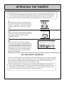
OPERATING THE TIMER(S)
Before operating the Timer(s), the clock time must be correct, and a starting time and finishing time
for the Timer(s) must be programmed. See pages 32 and 33. The two Timers operate in the same
way. This heater does not commence operation at the programmed starting time. It will attempt to
heat a room by the programmed starting time. See pre-heat page 35, for further explanation.
To select the Timer(s) to commence heating:
Check the time shown on the Digital Display is
correct. See page 32. Check the ON and OFF
times, for both Timers if necessary, see page
33.
Press the ON-OFF button to operate the heater.
The On indicator will glow green and the heater
will begin to operate. Select the desired
temperature setting.
Press the Timer 1 and/or Timer 2 button(s).
The Timer indicator(s) will glow and the heater
will remain on standby until one hour prior to the
time programmed into the selected Timer(s) is
reached. When this time is reached, the Timer
indicator will flash and the heater will operate.
The ON indicator glows red when the heater
commences operation.
AM
PM
Set Room
Temp
・
Time
Filter
ON / OFF
Child Lock Economy Timer 1
Timer 2 Override
SET AND FORGET OPERATION
Your heater can be operated to alternate between Timers automatically during cold weather by selecting
Timer 1 and Timer 2 together. Both Timer indicators will glow. The appliance will remain on standby at
intervals between the programmed finishing and starting time of each Timer. While the heater is
operating during programmed intervals the Timer indicator will flash.
If there is a power failure, the system memory will retain the Timer programs, and the clock will
stop at the time the power goes off. The clock will start again when the power comes back on, but
the time will be slow by the duration of the power failure. To set the clock to the correct time after
the power has come back on, simply follow the instructions on page 32.
– 34 –
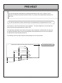
PRE-HEAT
This function operates automatically in conjunction with either of the Timers. When a Timer is
selected, the heater may operate anywhere within an hour prior to the programmed starting time of
the Timer.
The Pre-heat function will heat a room to the pre-set temperature by the programmed On Time.
This function is called Pre-heat due to the way it operates. The room temperature is sensed one hour
before reaching the programmed time of either Timer.
The temperature differential at the time of sensing the room temperature, combined with the data from
the previous operation governs exactly how long before the programmed On time the micro computer
will operate the heater and ignite the burner.
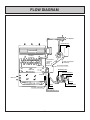
The following chart may help to improve understanding of the Pre-heat function.
TIME ELAPSED FROM IGNITION TO PRESET TEMPERATURE
Colder than usual
Warmer than usual
6:00
6:30
7:00
Programmed time
Later than average ignition
Average starting time
Earlaer than usual ignition
Room temperature sensed
– 35 –
Recorded by Micro Computer
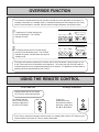
OVERRIDE FUNCTION
This function is intended to be used to manually override the current operation of the heater, For
example; if the heater is in standby mode (i.e. between finishing time and starting time of a Timer),
and the Override button is selected, then the heater will begin to operate, and heat the room.
To operate the Override simply press
the Override button. The Override
indicator will flash.
Timer 1
Timer 2 Override
AM
PM
Set Room
Temp
・
Time
To manually deactivate the Override simply
press the Override button again. The Override
indicator will go out, and the heater will return to
standby mode.
Timer 1
Timer 2 Override
AM
PM
Set Room
Temp
・
Time
The heater will continue to operate on Override until the Override button is pressed again, or one
of the Timers takes over the operation of the appliance. This means that the Override mode will
automatically drop out if a programmed Starting time is reached. The appliance will then return to
operating at times programmed into the Timer(s).
USING THE REMOTE CONTROL
To Turn ON or OFF
To Change Temperature
Remote Control will not turn heater
ON if Timer(s) have been selected.
To manually operate
when Timer(s) are not
selected, simply press
the ON or OFF button.
To alter the
temperature at any
time while the heater is
operating, simply press
the “▲”or “▼” buttons.
ON
OFF
If the Timer(s) have been selected, and the heater is in standby mode, and the OFF button on the
Remote Control is pressed, the Timer(s) will be deactivated.
– 36 –
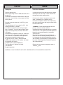
TESTING
CHECK
Testing Unit
Fault-Failure Procedure
Purge air from gas line.
Refer to pipe sizing chart if in doubt about the size of
the gas line.
Connection can easily be reached from the top, rear
of the unit. Check for leaks, using soapy water after
turning gas on.
If unable to get the unit to operate correctly, contact
Rinnai Agent, or Gas Utility. Please read the fault
finding charts before reporting faults.
Do not use this heater if any part has been under
water. Immediately call a qualified service
technician to inspect the heater and to replace any
part of the control system and any gas control which
has been under water.
Plug unit in and turn power on, (CAUTION 120V
inside unit).
Turn thermostat to “HI”, turn control to “ON”. Unit
should ignite within 10 seconds.
(If unit does not ignite first time it will spark again
after 10 seconds). If unit still does not ignite, there
may be air in the gas line, turn control “OFF” then
“ON” again.
Check pressure, regulator is factory set, if pressure
is incorrect, check supply before altering regulator.
Turn control to “OFF” position, remove pressure
manometer and replace test point screw.
Re light unit, on “HI” setting. Slide thermostat
control slowly towards the “LO” position, the heater
will cut down, then cut out.
(Depending on the room temperature).
Turn the power off. Replace the casing.
Turn power on.
Re check operation.
“WARNING” Do not operate appliance with the
panel(s) removed, cracked or broken.
Installation and repair should be done by a qualified
service person. The appliance should be inspected
before use and at least annually by a qualified
service person.
More frequent cleaning may be required due to
excessive lint from carpeting, bedding material, etc..
It is imperative that control compartments, burners
and circulating air passageways of the appliance be
kept clean. Ventilating system should be inspected
and cleaned annually.
Rinnai's service assistance telephone number is
1/800/621 9419.
WARNING: DO NOT OPERATE UNIT UNTIL PROPER INSTALLATION HAS BEEN COMPLETED.
– 37 –
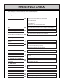
PRE-SERVICE CHECK
Before asking for a service call please check the following points.
These points are part of the normal operation of the unit.
■ At Ignition:
Heater does not operate.
Is the heater plugged in?
Have the fuses or breaker blown at the switch board?
Is there a power failure?
Is the air filter blocked?
Is anything blocking the outlet for the hot air?
Is the flue blocked?
Are timers set? Clear timers and operate again.
Warm air does not flow when the burner
lights.
The fan is started automatically after a short delay.
This is to allow the heat exchanger to warm up, helping to avoid cold draughts.
Smoke or strange smells are produced
on the first trial light up after installation.
This is caused by grease or oil and dust on the heat exchanger and will stop
after a short time.
Sharp clicking noises at ignition, or when
unit cuts down on the thermostat, or goes
out.
This is simply expansion noise from the heat exchanger.
■ During Combustion:
Clunking noise when the thermostat
operates.
This is the sound of the solenoid gas valves opening and closing.
Unit is not heating room.
Is the air filter blocked?
Is the set temperature high enough?
Is the warm air outlet blocked by anything?
Are the doors and windows of the room closed?
Air filter is blocked or the louvers are
blocked or obstructed.
Allow heater to cool, clean air filter, operate again.
Heater will not re-ignite after overheating.
Even after unit has cooled down the heater does not ignite again. Repair is
necessary.
Contact your local agent or Rinnai for a Service call.
■ When the unit is turned off.
Convection fan continues to run after
turning OFF.
This is to remove the residual heat from the heat exchanger, the fan will stop
when the heater cools down.
■ Other Points:
Steam is discharged from the flue terminal.
High efficiency appliances tend to discharge water vapor on cold days, this is
normal.
Unit cuts off without apparent reason.
Check whether filters are blocked, dirty filters will cause the heater of overheat.
Power Failure.
Switch OFF, then ON again when power is restored to re-set controls.
Remote control does not operate
Check battery. Try moving closer to heater.
– 38 –
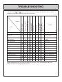
TROUBLE SHOOTING
Remote Control
doesn't work
Takes too long to
warm the room
Noisy ignition
Smell of gas
Combustion stops
during operation
Unusual combustion
Cause
No ON indicator
Problem
Burner doesn't ignite
Your RHFE-556FA /FTRA requires very little maintenance, simply clean the rear fan filter as needed
and wipe the outer case and louver section with a damp cloth.
Remedy
Not Plugged In
Plug In
Power Cut
Re-ignite manually after
power is restored
(Initial Installation)
Air In Gas Pipe
Purge air
(Installer)
Gas Filter Blocked
Service Call
Miss Ignition
Service Call
Flue terminal obstructed
Clear obstruction
Flue manifold not connected
Service Call
Louver obstructed
Clear obstruction
Air filter blocked
Clean filter
Gas Escape
Service Call
Child Proof Lock Set
Cancel Child Proof Lock
Gas turned off at meter
Turn gas on
Check battery (remote control)
Replace battery
On Timer is set
Cancel on timer
General maintenance items are not covered under unit's warranty. Such as cleaning dust, debris and
carbon from flame rod, and improper set up of unit.
– 39 –
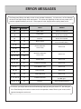
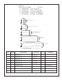
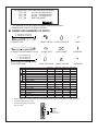
ERROR MESSAGES
The Energysaver 556 has the ability to check its own operation continuously. If a fault occurs, an Error Message
will flash on the Digital Display of the control panel. This assists with diagnosing the fault, and may enable you to
overcome a problem without a service call. Please quote the code displayed when enquiring about service.
CODE DISPLAYED
FAULT
REMEDY
11
Ignition failure
Check gas is turned ON.
Service call if repeated.
LO
12
Flame failure
Check gas is turned ON.
Service call if repeated.
68
14
Overheat
Clean filter
Service call if repeated.
HI
16
Room overheat
Lower room temperature
to less than 40°C(104°F).
72・76
31
Room Temperature
Sensor faulty
Service call.
Overheat Temperature
Sensor faulty
Service call.
556FAÁ
556FTRAÁ
60
76・80
32
64・68・72
33
68・72・76
34
LO・60・64
53
Sparker failure
Service call.
60・64・68
61
Combustion fan failure
Service call.
64・68
70
Faulty ON/OFF switch
Service call.
LO・60
71
Faulty solenoids
Service call.
80
72
Faulty Flame Rod
Service call.
72・76・80・HI
73
Communication Error
Turn heater OFF,
then ON again.
60・64・68・72・76
99
Flue blok
Check around flue terminal
In all cases, you may be able to clear the Error Message simply by turning the heater OFF, then ON again.
If the Error Message still remains or returns on the next operation, contact Rinnai or your nearest service
agent and arrange for a service call.
– 40 –
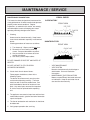
MAINTENANCE / SERVICE
MAINTENANCE SUGGESTIONS
VISUAL CHECK
SATISFACTORY
This heater has been designed and constructed for
a long performance life when installed and operated
properly under normal conditions. Regular
inspections, as outlined in this section, are strongly
recommended as means of keeping your heater
operating efficiently throughout the season.
FRONT VIEW
1. Cleaning
Heater must be cleaned annually. Keep heater
clear of dust and debris especially in and around
burner.
Cleaning procedures of heater are as follows:
UNSATISFACTORY
FRONT VIEW
1) Turn heater off. Allow to cool for one hour.
2) Remove the Front Panel by removing
screws. See parts breakdown on panels.
3) Use pressurized air to remove dust from
around main burner.
4) Use soft dry cloth to wipe cabinet.
DO NOT DAMAGE OR DISTORT ANY PARTS OF
HEATER.
•
•
DO NOT USE WET CLOTH OR SPRAY
CLEANERS ON BURNER.
2. Visual check of main burner flames.
Flame pattern should be as shown in the
following Figures.
The burner must flame evenly over the entire
surface when operating correctly. The flame
must burn with a clear blue stable flame. See
parts breakdown of burner for location of view
ports. Any and all parts removed for inspection
or service must be replaced before operating
unit.
•
3. The appliance area must be kept clear and free from
combustible materials, gasoline and other flammable
vapors and liquids.
4. The flow of combustion and ventilation air should not
be obstructed.
5. Verify proper operation after servicing.
– 41 –
VENT MAINTENANCE
VENT SYSTEM
Must be checked annually for blockage or
deterioration. See vent installation
instructions.
MAINTENANCE ELECTRIC MOTORS
Motors are permanently lubricated and need
no lubrication. Keep fan and motor free of
dust and dirt clean annually.
– 42 –
WW
WW
OHS
H2
r
OHS
H1
No 3〔130℃〕
BL
POV
ER
H3
gr/y
SP
W
No 1〔130℃〕 No 2〔90℃〕
OHS
〔152℃〕
TF
W
RCR
r or y gr bl pl gy w bk
r bl bl
W
bk
G
r
bl
gy
or
38
37
W142
bk 41
gy gy
43 45
44 46
bk
SV2
SV1
39 r
40 Y
H
F
bk
r
OFF
1234
MARK
MS
TH
TF
F
ER
POV
TR
FR
TR
130℃
TF
gy 21
r 22
20
16
3A
15
12
13
4
5
6
7
8
9
gr/y
W
W
Y
Y
bk
W
AC
120V
FM
W
gy
OH.TH
TH
r
BL
POV
ER
H3
No 3〔130℃〕
OHS
WW
OHS
H2
OHS
H1
gr/y
SP
W
No 1〔130℃〕 No 2〔90℃〕
W
WW
No 2〔152℃〕
TF
r or y gr bl pl gy w bk
r bl bl
W
bk
G
r
bl
gy
or
38
37
W142
bk 41
gy gy
43 45
44 46
bk
SV2
SV1
39 r
40 Y
H
F
bk
r
OFF
1234
TR
130℃
TF
gy 21
r 22
20
16
3A
15
12
13
4
5
6
7
8
9
gr
bk W
18
17
〔F〕
C
A
K
gy gy
19
D B
〈556FA 〉
FR
Y
Y
Y r
bl W
2728 29 30
Y or bl
E1
bk W
23 24 25 26
E
Y r
J
34 3536
31 3233
bk gy r
I
123
gr/y
W
W
Y
Y
bk
W
AC
120V
TH
W
gy
OH.TH
FM
123
TB
SW5, TEST SWITCH
SW4 POV, PRESSURE ADJUST SWITCH〔Lo〕
SW2 FM, ADJUST SWITCH〔Lo〕
SW3 POV, PRESSURE ADJUST SWITCH〔Hi〕
SW6, DIP SWITCH
SW1 FM, ADJUST SWITCH〔Hi〕
PART NAME
OVER HEAT THERMISTOR
OVER HEAT SWITCH
CONVECTION FAN MOTOR
SPARKER
MAIN SOLENOID VALVE 1∼2
COMBUSTION FAN MOTOR
REMOTE CONTROL RECEIVER
TERMINAL BLOCK
47 48 49 50 51 52 53 54 55 56 57 58 59 60 61 62 63 64 65 66 67 68 69 70 71
r bl bl bl bl bl bl bl bl bl
CONTROL DISPLAY UNIT
MS
MARK
OH. TH
OHS1∼3
FM
SP
SV1∼2
BL
RCR
TB
If any of the original wire as supplied with the appliance must be
replaced, it must be replaced with a wire of a least a 194°F
temperature rating and number 18AWG or its equivalent.
“CAUTION: Label all wires prior to disconnection when servicing
controls. Wiring errors can cause improper and dangerous operation.”
Verify operation after servicing
gr
bk W
18
17
〔F〕
C
gy gy
19
D B
A
K
123
123
TB
SW5, TEST SWITCH
SW4 POV, PRESSURE ADJUST SWITCH〔Lo〕
FLAME ROD
PART NAME
MAIN SWITCH
THERMISTOR
THERMAL FUSE
FUSE
ELECTRODE
MODULATING SOLENOID VALVE
TRANSFORMER
SW2 FM, ADJUST SWITCH〔Lo〕
SW3 POV, PRESSURE ADJUST SWITCH〔Hi〕
SW6, DIP SWITCH
SW1 FM, ADJUST SWITCH〔Hi〕
〈556FTRA 〉
FR
Y
Y
Y r
Y or bl
bl W
2728 29 30
E1
bk W
23 24 25 26
E
Y r
J
34 3536
31 3233
bk gy r
I
47 48 49 50 51 52 53 54 55 56 57 58 59 60 61 62 63 64 65 66 67 68 69 70 71
r bl bl bl bl bl bl bl bl bl
MS
orange
white
yellow
grey
CONTROL DISPLAY UNIT
w
y
gy
or
CODE
COLOR
bk
black
bl
blue
br
brown
gr
green
gr/y green/yellow
pl
purple
red
r
WIRING DIAGRAM
CONSUMER SUPPORT
Warranty Information
The installer is responsible for your heater’s correct installation.
Please complete the information below to keep for your records:
Purchased from:
Address:
Phone:
Date of Purchase:
Model No.:
Serial No.:
Installed by:
Installer’s License No.:
Address:
Phone:
Date of Installation:
Limited Warranty
Gas Direct Vent Wall Furnace
What is covered?
This Warranty covers any defects in materials or workmanship, subject to the terms stated below. This Warranty
extends to the original purchaser and subsequent transferees, but only while the product remains at the site of
the original installation. This Warranty only extends through the first installation of the product and terminates if
the product is moved or reinstalled at a new location.
How long does coverage last?
Item
Period of Coverage
Heat Exchanger
10 years from date of purchase *
All Other Parts
5 years from date of purchase
Reasonable Labor
2 years from date of purchase
– 43 –
Limited Warranty - continued
What will Rinnai do?
Rinnai will repair any part or component that is defective in materials or workmanship as set forth as follows. All
repair parts must be genuine Rinnai parts. All repairs or replacements must be performed by an individual or
servicing company that has been authorized by Rinnai. Rinnai will pay reasonable labor charges associated
with the repair or replacement of any part or component.
Replacement of the product may be authorized by Rinnai only. Rinnai does not authorize any person or
company to assume for it any obligation or liability in connection with the replacement of a product. If Rinnai
determines that repair of a product is not possible, Rinnai will replace the product with a comparable product, at
Rinnai’s discretion.
* If the Heat Exchanger fails due to a defect in
material or workmanship within the sixth (6)
through the tenth (10) year from the date of
purchase, Rinnai will make the following
allowances toward the purchase of a
replacement Heat Exchanger:
Heat Exchanger
Year of Failure
Allowance
6
50%
7
40%
8
30%
9
20%
10
10%
How do I get service?
You must contact a qualified/authorized service provider for the repair of a product under this Warranty. For the
name of a qualified/authorized service provider please contact your place of purchase, visit the Rinnai website
(www.rinnai.us), call Rinnai at 1-800-621-9419 or write to Rinnai at 103 International Drive, Peachtree City,
Georgia 30269.
Proof of purchase is required to obtain warranty service. You may show proof of purchase with a dated sales
receipt, or by registering within 30 days of purchasing the product. To register your appliance, please visit
www.rinnairegistration.com. For those without internet access, please call 1-866-RINNAI1 (746-6241).
Receipt of Registration by Rinnai will constitute proof-of-purchase for this product. However, Registration is
not necessary in order to validate this Warranty.
What is not covered?
This Warranty does not cover any failures or operating difficulties due to accident, abuse, misuse, alteration,
misapplication, force majeure, improper installation, improper conversion*, improper maintenance or service, or
for any other causes other than defects in materials or workmanship. This Warranty does not apply to any
product whose serial number or manufacture date has been defaced.
* Improper conversion includes conversions for inventory adjustment.
Rinnai is not liable for any special, incidental, indirect or consequential damages that may arise, including
damage to person or property, loss of use, or inconvenience. Some states do not allow the exclusion or
limitation of incidental or consequential damages, so the above limitation may not apply to you.
Limitation on implied warranties
Any implied warranties of merchantability and fitness arising under state law are limited in duration to the period
of coverage provided by this limited Warranty, unless the period provided by state law is less. Some states do
not allow limitations on how long an implied Warranty lasts, so the above limitation may not apply to you.
This Warranty gives you specific legal rights, and you may also have other rights which vary from state to state.
– 44 –
SCHEMATIC DIAGRAM
– 45 –
– 46 –
– 47 –
– 48 –
– 49 –
PARTS LIST
Note: If no part number is listed for the 556FTRA
this means if uses the same part as the 556FA .
– 50 –
Note: If no part number is listed for the 556FTRA
this means if uses the same part as the 556FA .
– 51 –
Note: If no part number is listed for the 556FTRA
this means if uses the same part as the 556FA
– 52 –
.
Note: If no part number is listed for the 556FTRA
this means if uses the same part as the 556FA .
– 53 –
No.
PART NAME
PART No.
556FAÁ
QTY
714
TF COVER
556F-524
1
715
FR LEAD
431F-1430
1
716
OVERHEAT SWITCH
ES-01174
1
717
EARTH LEAD
550F-0818
2
719
OHS3 BRACKET
556F-570
1
720
OHS3 LEAD
556F-571
1
721
MOTOR LEAD
431F-1220
1
801
802
803
804
805
806
807
808
809
810
811
812
813
814
815
816
817
818
819
820
821
822
823
824
900
901
902
903
904
905
906
907
908
909
910
911
912
SCREW
SCREW
SCREW
SCREW
SCREW
SCREW
SCREW
SCREW
SCREW
SCREW
SCREW
SCREW
SCREW
SCREW
SCREW
SCREW
SCREW
SCREW
SCREW
SCREW
SCREW
SCREW
SCREW
SCREW
CONVERSION KIT FOR L.P.G
CONVERSION KIT FOR N.G.
RATING PLATE
RATING PLATE
OPERATION LABL
FILTEL LABEL
CAUTION LABEL
CAUTION LABEL D
CAUTION LABEL
STICKER
CAUTION LABEL
RATING PLATE SUPPORT LABEL
RATING PLATE SUPPORT LABEL
ZAA0420SZ
ZEAB0408UK
ZEAB0408SZ
ZEDB0412SZ
ZEAB0410SZ
ZEDB0408SZ
ZEDB0416SZ
ZHAE0306SZ
CP-30421-1
ZDAA0410SZ
ZEAB0406SZ
ZEDB0410SZ
ZEAB0408SC
ZDAA2.608SN
ZAA0422SZ
ZBA0410SZ
ZHAA0406SZ
ZEDB0408SC
CP-30486-2
ZEAB0414SZ
CP-30408
ZBB0410SC
ZAA0408SZ
ZHAA0410SZ
556F-2004-3
〃
-2
CP-74167 -5
-6
CP-74168 -5
-6
431F-1810
1001F-1651
431F-1830
1001F-1652
1001F-1656
1
1
1
1
1
1
1
1
1
431F-1840
431F-1841
1
1
1001F-1654
CP-74253 -1
-2
CP-74254 -1
-2
1
1
1
PART No.
556FTRAÁ
266°F OFF
CP-72135 -13
-14
CP-72151 -13
-14
LPG
NG
LPG
NG
556F-2011
Note: If no part number is listed for the 556FTRAÁ this means if uses the same part as the 556FAÁ.
– 54 –
REMARKS
LPG
NG
FLOW DIAGRAM
Flue Manifold
Combustion Fan
P.C.B
Convection Fan
Sub Heat
Exchanger
Thermal Fuse
Over Heat
Switch
(No.1)
Room Temperature
Thermistor
Over Heat Thermistor
Flame Rod
Main Heat
Exchanger
Modulating Valve
Solenoid Valve No.1
Electrode
Gas Filter Warm Air
Gas Inlet
Injector
Over Heat Switch(No.2)
Damper
Main Burner
Over Heat Switch(No.3)
– 55 –
Solenoid Valve No.2
Vent sizes:
5 Vent lengths are available.
inch (mm)
S Vent suits walls 3" 4 1/2" (75 115)
A Vent suits walls 4 1/2" 9 1/2" (115 240)
B Vent suits walls 9 1/2" 15 3/4" (240 400)
C Vent suits walls 15 3/4" 23 5/8" (400 600)
D Vent suits walls 23 5/8" 31 1/2" (600 800)
1
S
2
A
3
B
4
C
5
D
NO.
RANK
1
M
VENT KIT S
FOT-150
1
2
M
VENT KIT A
FOT-151
1
3
M
VENT KIT B
FOT-152
1
4
M
VENT KIT C
FOT-153
1
5
M
VENT KIT D
FOT-154
1
6
PARTS NAME
PARTS NO.
QTY
1
RUBBER SEAL
– 56 –
REMARKS
SEE PAGE 14.
EXTENSION SET PARTS AND INSTALLATION GUIDE
FOT 155
20"(0.5m) EXTENSION SET
FOT 156
40"(1m) EXTENSION SET
FOT 157
80"(2m) EXTENSION SET
FOT 158
BENT ELBOW SET
• This extension set is to be used for installations requiring extra distance.
MAXIMUM VENT LENGTH 13' WITH 2 ELBOWS
■ NAMES AND NUMBERS OF PARTS
A FOT-155(11.4-20.3 inch)
B FOT-156(21.0-39.6 inch)
1EXHAUST PIPE
2EXHAUST PIPE(STRAIGHT) 40 inch
4BENT ELBOW
7PIPE STOPPER B
0NUT
5HOSE JOINT
8PIPE CLAMP
ASCREW A
9WALL-FIXTURE
BSCREW B
A FOT-155(29.5 inch)
B FOT-156(49.2 inch)
C FOT-157(78.7 inch)
6PIPE STOPPER A
3AIR INTAKE HOSE
A
B
1
2
A
B
C
3
4
5
6
7
8
9
0
A
B
※
FOT-155
1
EXHAUST PIPE
EXHAUST PIPE
EXHAUST PIPE(STRAIGHT)
AIR INTAKE HOSE
AIR INTAKE HOSE
AIR INTAKE HOSE
BENT ELBOW
HOSE JOINT
PIPE STOPPER A
PIPE STOPPER B
PIPE CLAMP
WALL FIXTURE
NUT
SCREW A
SCREW B
FOT-156
FOT-157
1
1
1
FOT-158
1
1
1
1
1
1
1
2 SET
2
2
2
4
1
1
1
3 SET
3
3
3
6
1
2
1
4 SET
4
4
4
8
1
When the appliance is installed using a vent extension that exceeds 6 feet you must change the jumper on the vent
extension terminal block as shown.
Terminal is located at the rear of unit
next to gas inlet.
3
2
1
– 57 –
FOR DIRECT
EXHAUST
FOR USED
EXTENSION KITS
(MORE THAN 4feet 1L)
■ TYPES COMPATIBLE WITH EXTENSION SET
RHFE-431FA /556FA /FTRA
INSTALLING AN EXTENSION KIT
Installing an extension kit requires construction of an air line and the exhaust line. The air line is connected
between the Air Supply Elbow at the rear of the heater and the air inlet port on the Flue pipe.
Similarly, the exhaust line is connected between the joint pipe at the rear of the heater, and the exhaust
port on the Flue pipe.
Caution: Check to see there is no debris inpipe or hose.
■ HOW TO INSTALL
MODEL:RHFE-431FA /556FA
/FTRA
Example:Using 2 sets of extension set and 1 bent set.
Example:Using 80 inches slide pipe set.
Vent manifold
(comes with main unit)
Air intake elbow
(comes with main unit)
Pipe stopper A
Pipe stopper B
Pipe stopper A
Pipe clamp
Pipe stopper A
Bent elbow
Pipe stopper B
Exhaust pipe
Pipe stopper A
Pipe clamp
Hose joint
Pipe stopper A
Pipe stopper B
Air intake elbow
(comes with main unit)
Pipe clamp
40 inch straight pipe
Vent manifold
(comes with main unit)
Exhaust pipe
Pipe clamp
Hose joint
Hose joint
Air intake hose
Pipe stopper A
Air intake hose
Pipe stopper A
Pipe stopper B
Pipe stopper B
1. How to connect exhaust pipes
Exhaust pipe
Exhaust pipe
Fit inside
Male end
Pipe stopper B
Pipe stopper A
Male end
Female end
Female end
Pipe stopper B
To connect the exhaust pipes, fit the male end into the female end and clamp with pipe stopper A to prevent
slipping. The exhaust pipe can be telescoped to the required length; do not cut it.
Female end
Male end
Connect bent pipe
Fit inside
Pipe stopper A
– 58 –
2. How to connect air intake hose
Air intake hose
Air intake hose
Hose joint
Screw in counterclockwise
Main unit air intake hose
Air intake elbow
Screw hose joint half of its length onto the air intake hose, then screw another air intake hose into the joint.
The hose can be cut to the required length.
IMPORTANT: The PVC air line is longer than the exhaust line and may need to be cut to size. Be sure,
however, to thoroughly deburr all rough edges.
3. Affixing the air intake hose and exhaust pipe
NOTE: Maintain 1" clearance between exhaust pipe
and combustible materials (0" clearance between
exhaust pipe and non-combustible materials).
Screw A
Pipe clamp
Exhaust pipe
Wall fixture
Pipe clamp
Adjust the angle
Air intake
hose
Air intake
hose
Wall
Screw B
Screw A
4. How to use the bent pipe
Exhaust pipe
Wall
Nut
With the exhaust pipes inserted into the ends, bend
the bent pipe to the angle reguired for installation.
This part is mainly used for curves and for connection
to vent terminal.
・Set the air intake hose and exhaust pipe into the pipe
clamps, screw the clamp onto the wall fixture, and affix
to the wall with screw B.
・The air intake hose and exhaust pipe can also be
screwed onto the wall using the pipe clamp and
the nut.
■ CAUTIONS
1. Maximum extendable length
FOR BEST ROOM AIR HUMIDITY, KEEP WATER
IN THE HUMIDIFIER TRAY.
2. To prevent water condensation
・13 feet, 2 bends
・The bend where the hose and pipes leave the body is
not counted.
・The air intake hose should run along the exhaust pipe.
CAUTION
Never allow the exhaust pipe to sag, as condensed
water may accumulate and cause incomplete
combustion.
Condensed water
may accumulate
here, and cause a blockage
preventing combustion.
– 59 –
3˚ slope(approximate)
Less than 8 ft.
3. Condensed water formed by
combustion, will run back to the
unit, and may overflow from the
condensation pan if pipes are
longer then 8 feet. Therefore, pipes
exceeding these lengths should be
made to drain to the outside by
giving their horizontal portions 3˚ or
more downward and outward slope.
4. Wherever the air intake hose and exhaust pipe
run sideways, try to have the exhaust pipe on
top (to prevent the air intake hose from sagging
onto the exhaust pipe).
Exhaust pipe
Exhaust pipe
Air intake hose
Air intake hose
QUALIFIED INSTALLING AGENCY
The installation must conform to local codes, in the
absence of local codes, the installation must
conform with American National Standard (National
Fuel Gas Code) known as NFPA 54 and ANSI
Z223.1.1992.
Available from the American National Standards
Institute, Inc., 1430 Broadway, New York, N.Y. 10018
or from the National Fire Protection Association,
470 Atlantic Avenue, Boston, Mass. 02210.
– 60 –
103 International Drive,
Peachtree City, Georgia 30269
Phone:1-800-621-9419
Fax:1-888-474-6624
www.rinnai.us
Register your product at www.rinnairegistration.com or
call 1-866-RINNAI1 (746-6241)
556F-2009×15(00)
Printed in Japan
2008.09