1
WMS 470
BEDIENUNGSANLEITUNG (V 1.00) S. 2
.
Bitte vor Inbetriebnahme des Gerätes lesen!
USER INSTRUCTIONS (V 1.00)
. . . . . . .
p. 24
. . . . . . . . . . . . . . .
p. 46
Please read the manual before using the equipment!
MODE D’EMPLOI (V 1.00)
Veuillez lire cette notice avant d’utiliser le système!
ISTRUZIONI PER L’USO ( V 1.00)
. . . .
p. 68
. . . . . . . . . . .
p. 90
Prima di utilizzare l’apparecchio, leggere il manuale!
MODO DE EMPLEO (V 1.00)
¡Sirvase leer el manual antes de utilizar el equipo!
INSTRUÇÕES DE USO (V 1.00)
Favor leia este manual antes de usar o equipamento!
. . . . . . .
p. 112
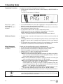
Thank you...
Symbols Used
...for purchasing an AKG product. This manual contains important instructions for setting up
and operating your equipment. Please take a few minutes to read the instructions below
carefully before operating the equipment. Please keep the manual for future reference.
We hope you enjoy using your system!
↯
L
The lightning flash with arrowpoint in an equilateral triangle means that there are
dangerous voltages present within the unit.
The exclamation point in an equilateral triangle on the equipment indicates that it
is necessary for the user to refer to the User Manual. In the User Manual, this
symbol marks instructions that the user must follow to ensure safe operation of
the equipment.
Firmware
• AKG continually improves the internal firmware of this wireless system in order
to meet changing customer needs in the best possible way. Should your system use a different firmware version than the one described in this user manual, some functions may differ from the related instructions.
• To find out the actual firmware version implemented in your system, please
check the menu. The firmware version described in this user manual is stated
on the cover page.
• Before you read on, we recommend comparing the receiver firmware version
against the version described in the manual. If the two versions are not identical, please visit www.akg.com to find out about the latest changes.
• The display on your handheld transmitter or bodypack transmitter indicates the minimum remaining battery capacity in transmitter operating hours.
Important Note
Important Note
Transmitter Battery
• To ensure an accurate readout, do not use any batteries other than
- new, high quality AA size (LR6) alkaline dry batteries from Duracell or Energizer,
- AA size (FR6) lithium batteries,
or
- high quality AA size NiMH rechargeable batteries with a capacity of 2100 mAh or
higher.
- In the "BAT.TYP" menu, select the battery type you inserted ("LR6", "FR6", "HR6
(NiMH)) or automatic battery detection mode ("AUTO").
- In "AUTO" mode, using weak or very old batteries may cause incorrect capacity indications. In this case, select the battery type manually.
• Since the chemical parameters of batteries take some time to stabilize, the system may
correct the battery indication (type and remaining capacity) about 10 to 30 minutes
after switching power to the transmitter on.
• Lithium batteries have a life of up to 14 hours. The display, however, will only indicate
a maximum of 10 hours. With new lithium batteries, the display will constantly indicate
"10h" during the first four operating hours.
24
WMS 470
Table of Contents
Page
Figs. 1-17 ...............................................................................................................ii-vii
1 Safety and Environment.....................................................................................26
Safety .................................................................................................................26
Environment ........................................................................................................26
2 Packing List and Optional Accessories...............................................................27
Systems and Components.....................................................................................27
Optional Accessories ............................................................................................27
3 General ..............................................................................................................29
Intoduction ..........................................................................................................29
Receiver ..............................................................................................................29
Handheld Transmitter ...........................................................................................30
Bodypack Transmitter ...........................................................................................31
4 Setting Up ..........................................................................................................32
Receiver ..............................................................................................................32
Rack Mounting ................................................................................................32
Connecting Antennas .......................................................................................32
Positioning the Receiver ...................................................................................33
Connecting the Receiver to a Mixer/Amplifier......................................................33
Connecting the Receiver to Power .....................................................................33
LOCK Mode.....................................................................................................33
Transmitters ........................................................................................................34
Inserting the Battery.........................................................................................34
Bodypack Transmitter.......................................................................................34
Connecting a Microphone or Instrument ........................................................34
Locking the ON-MUTE/PRG-OFF Switch ........................................................34
Setting Input Gain........................................................................................34
Optional RMS 4000 Remote Mute Switch ......................................................35
Handheld Transmitter .......................................................................................35
Setting Input Gain........................................................................................35
Handheld and Bodypack Transmitters ................................................................35
SILENT Mode ..............................................................................................35
Selecting Battery Type..................................................................................35
5 Operating Notes .................................................................................................36
Powering Up the Receiver .....................................................................................36
Powering the Transmitters.....................................................................................36
Muting the Transmitters ........................................................................................36
System Adjustments.............................................................................................37
Automatic Setup (Multichannel Systems) ...........................................................37
Manual Group/Channel Setup ...........................................................................37
Selecting Frequencies Manually ........................................................................37
Setting Handheld Transmitter Gain.....................................................................37
Programming Transmitters ...............................................................................38
Multichannel Systems ......................................................................................38
Battery Management (handheld and bodypack transmitters)................................38
6 Advanced Functions (EXTRA Menu) ...................................................................39
Receiver ID ..........................................................................................................39
Status & Warning Messages..................................................................................39
REHEARSAL - Soundcheck....................................................................................39
SQUELCH ............................................................................................................40
Pilot Tone.............................................................................................................41
FACTORY RESET ..................................................................................................41
INFO ..................................................................................................................41
INTRO .................................................................................................................41
7 Microphone Technique.......................................................................................42
Handheld Transmitter ...........................................................................................42
Lavalier Microphones ...........................................................................................43
Headworn and Instrument Microphones .................................................................43
8 Cleaning.............................................................................................................43
9 Troubleshooting .................................................................................................44
10 Specifications ....................................................................................................45
WMS 470
25
1 Safety and Environment
Safety
•
•
•
•
•
•
•
•
•
•
•
•
Environment
•
•
•
Do not expose it to direct sunlight, excessive dust, moisture, rain, mechanical vibrations, or shock.
Do not spill any liquids on the equipment and do not drop any objects through the ventilation slots
in the equipment.
The equipment may be used in dry rooms only.
Before connecting the equipment to power, check that the AC mains voltage stated on the included
power supply is identical to the AC mains voltage available where you will use the equipment.
Operate the equipment with the included power supply with an output voltage of 12 VDC only. Using
adapters with an AC output and/or a different output voltage may cause serious damage to the
equipment.
The equipment should be opened, serviced, and repaired by authorized personnel only. The equipment contains no user-serviceable parts.
Operate the equipment off voltages between 90 VAC and 240 VAC only. Using a different power voltage may cause serious damage to the unit!
If any solid object or liquid penetrates into the equipment, shut down the sound system immediately.
Disconnect the power cable from the power outlet immediately and have the equipment checked
by AKG service personnel.
Do not place the equipment near heat sources such as radiators, heating ducts, or amplifiers, etc.
and do not expose it to direct sunlight, excessive dust, moisture, rain, mechanical vibrations, or
shock.
To avoid hum or interference, route all audio lines, particularly those connected to the microphone
inputs, away from power lines of any type. If you use cable ducts or conduits, be sure to use separate ones for the audio lines.
Clean the equipment with a moistened (not wet) cloth only. Be sure to disconnect the equipment from
the power outlet before cleaning the equipment! Never use acidic or scouring cleaners or cleaning
agents containing alcohol or solvents since these may damage the enamel and plastic parts.
Use the equipment for the applications described in this manual only. AKG cannot accept any liability for damages resulting from improper handling or misuse.
Be sure to dispose of dead batteries as required by local waste disposal rules. Never throw batteries into a fire (risk of explosion) or garbage bin.
The packaging of the equipment is recyclable. Dispose of the packaging in an appropriate container provided by the local waste collection/recycling entity and observe all local legislation relating to waste disposal and recycling.
When scrapping the equipment, remove the batteries, separate the case, circuit boards, and cables,
and dispose of all components in accordance with local waste disposal rules.
FCC Statement
The HT 470 D5, HT 470 C5, and PT 470 have been tested and found to comply with the limits for a low-power auxiliary station pursuant to Part 74 of the FCC Rules. The
SR 470 has been tested and found to comply with the limits for a Class B digital device, pursuant to Part 15 of the FCC Rules. These limits are designed to provide reasonable protection against harmful interference in a residential installation. This equipment generates, uses, and can radiate radio frequency energy and, if not installed and used
in accordance with the instructions, may cause harmful interference to radio communications. However, there is no guarantee that interference will not occur in a particular
installation. If this equipment does cause harmful interference to radio or television reception, which can be determined by turning the equipment off and on, the user is encouraged to try to correct the interference by one or more of the following measures:
•
•
•
•
Reorient or relocate the receiving antenna.
Increase the separation between the equipment and the receiver.
Connect the equipment into an outlet on a circuit different from that to which the receiver is connected.
Consult the dealer or an experienced radio/TV technician for help.
Shielded cables and I/O cords must be used for this equipment to comply with the relevant FCC regulations.
Changes or modifications not expressly approved in writing by AKG Acoustics may void the user’s authority to operate this equipment.
The SR 470 complies with Part 15 of the FCC Rules. Operation is subject to the following two conditions: (1) this device may not cause harmful interference, and (2) this device must accept any interference received, including interference that may cause undesired operation.
USA only: FCC CONSUMER ALERT
Most users do not need a license to operate this wireless microphone system.
Nevertheless, operating this microphone system without a license is subject to
certain restrictions: the system may not cause harmful interference; it must operate at a low power level (not in excess of 50 milliwatts); and it has no protection from interference received from any other device.
Purchasers should also be aware that the FCC is currently evaluating use of wireless microphone systems, and these rules are subject to change. For more information, call
the FCC at 1-888- CALL-FCC (TTY: 1-888-TELL-FCC) or visit the FCC’s wireless microphone website at www.fcc.gov/cgb/wirelessmicrophones.
26
WMS 470
2 Packing List and Optional Accessories
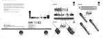
• Check that your package contains all the components listed for your system below. If anything is missing, please contact your AKG dealer.
WMS 470 D5 Set
• 1 x SR 470 diversity receiver
• 1 x HT 470 D5 transmitter
• 2 x BNC UHF antennas
• 1 x Power supply
• 1 x LR6 AA size dry battery
• 1 x RMU 4000 1U rack mount kit
• 1 x Stand adapter
WMS 470 C5 Set
• 1 x SR 470 diversity receiver
• 1 x HT 470 C5 transmitter
• 2 x BNC UHF antennas
• 1 x Power supply
• 1 x LR6 AA size dry battery
• 1 x RMU 4000 1U rack mount kit
• 1 x Stand adapter
WMS 470 Instrumental Set
• 1 x SR 470 diversity receiver
• 1 x PT 470 transmitter
• 2 x BNC UHF antennas
• 1 x Power supply
• 1 x LR6 AA size dry battery
• 1 x RMU 4000 1U rack mount kit
• 1 x MK/GL instrument/guitar cable (1/4"
to mini XLR)
• 1 x Terminal connector for locking the
ON-MUTE/PRG-OFF switch
WMS 470 Presenter Set
• 1 x SR 470 diversity receiver
• 1 x PT 470 transmitter
• 2 x BNC UHF antennas
• 1 x Power supply
• 1 x LR6 AA size dry battery
• 1 x C 555 L flexible headworn microphone
• 1 x RMU 4000 1U rack mount kit
• 1 x CK 99 L lavalier microphone
• 1 x Terminal connector for locking the
ON-MUTE/PRG-OFF switch
WMS 470 Sports Set
• 1 x SR 470 diversity receiver
• 1 x PT 470 transmitter
• 2 x BNC UHF antennas
• 1 x Power supply
• 1 x LR6 AA size dry battery
• 1 x RMU 4000 1U rack mount kit
• 1 x C 544 L rugged headworn microphone
• 1 x Terminal connector for locking the
ON-MUTE/PRG-OFF switch
SR 470
• 1 x SR 470 diversity receiver
• 2 x BNC UHF antennas
• 1 x RMU 4000 1U rack mount kit
• 1 x Power supply
HT 470 C5
• 1 x HT 470 C5 transmitter
• 1 x LR6 AA size dry battery
• 1 x PB 1000 presence boost adapter
• 1 x Stand adapter
HT 470 D5
• 1 x HT 470 D5 transmitter
• 1 x LR6 AA size dry battery
• 1 x Stand adapter
PT 470
• 1 x PT 470 transmitter
• 1 x LR6 AA size dry battery
Remote Antenna System
• SRA 2 W – Passive directional antenna
• SRA 2 B/W – Active directional antenna
• RA 4000 W – Passive omnidirectional antenna
• RA 4000 B/W – Active omnidirectional antenna
• PS 4000 W – Active antenna splitter
• AB 4000 – Antenna booster
• MK PS – Antenna cable, 2 ft./65 cm
• MKA 5 – Antenna cable, 16 ft./5 m
• MKA 20 – Antenna cable, 66 ft./20 m
• 0110E01890 – Front-mount antenna cable
WMS 470
Systems and
Components
Optional Accessories
27
2 Packing List and Optional Accessories
Charging System
• CU 400 charger for PT 470 and HT 470
Optional components for HT 470 Handheld transmitter
• W 3004 – Windscreen with color code strips
• PPC 1000 – Polar pattern converter (for HT 470 C5 only)
• Stand adapter
Optional components for PT 470 bodypack transmitter
• MK/GL – Instrument/guitar cable (1/4" to mini-XLR)
• HC 577 WR – Flesh tone headworn microphone (omnidirectional)
• C 520 L – Vocal headworn microphone (cardioid)
• C 555 L – Speech optimized headworn microphone (cardioid)
• C 544 L – Rugged headworn microphone (cardioid)
• C 417 L – Lavalier microphone (omnidirectional)
• CK 99 L – Lavalier microphone (cardioid)
• CK 77 WR – Flesh tone or black lavalier microphone (omnidirectional)
• C 411 L – Instrument pickup (vibration pickup)
• C 516 ML – Accordion microphone
• C 518 ML – Drum microphone (snare drum, bongos, etc.)
• C 519 ML – Wind instrument microphone (saxophone, trumpet, clarinet, etc.)
• RMS 4000 – Remote mute switch
• For more options and antenna accessories, please refer to the current AKG catalog or
folder, or visit www.akg.com. Your dealer will be glad to help.
28
WMS 470
3 General
The WMS 470 wireless microphone system comprises the SR 470 stationary diversity receiver, handheld transmitters HT 470/C5 with C 5 microphone element and HT 470/D5 with
D 5 microphone element, and the PT 470 bodypack transmitter. The receiver and transmitters operate in a 30 MHz subband of each frequency set within the 500 MHz to 865 MHz
UHF band. You can select the receiving frequency from the preprogrammed frequency groups
and subchannels of your receiver or set it directly in 25 MHz-increments. Both the handheld
and the bodypack transmitter are set to the parameters selected on the receiver via infrared
transmission.
Receiver
Front Panel
1 POWER: Switches power to the unit on or off.
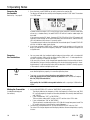
2 LCD display: The receiver provides a backlit LCD display.
a
Refer to fig. 1 on page iii.
c
b
f
Introduction
d
e
The display indicates all receiver parameters:
a RF bargraph indicating the field strength of the received signal
b Alphanumeric display of the current setting
c Parameter to be adjusted, mode
d Audio bargraph indicating the received audio level
e LOCK symbol
f Available channels (for automatic frequency setup)
• If one or more warning functions are activated, the display will be backlit in red when
a critical condition occurs. As long as all parameters are within their normal ranges,
the display is backlit in green.
3 : These three keys set the various parameters of the receiver.
• In LOCK mode:
Short push on or : scrolls through the Frequency, Preset, and receiver Name
screens.
Long push on : selects SETUP mode.
• In SETUP mode only:
Short push on : Calls up a parameter for adjustment or confirms a selected value.
Long push on : selects LOCK mode.
Short push on : selects a menu item or decreases a parameter value.
Short push on : selects a menu item or increases a parameter value.
4,5 RF LEDs: The green OK LED (4) is lit to indicate the receiver is receiving RF signal, the
red MUTE LED (5) indicates that no signal is being received.
6 A and B diversity LEDs: These two LEDs are lit to indicate which of the two antennas
is currently active.
7 AF LEDs: Indicate the received audio level:
OK (green): -40 dB to +3 dB
CLIP (red): >3 dB (overload)
WMS 470
29
3 General
8 Infrared emitter: Transmits frequency data from the receiver to the handheld or bodypack transmitter. It also transmits the audio gain setting selected on the receiver to the
handheld transmitter.
The infrared emitter has a very narrow radiation angle (approx. 10°) and a maximum
range of 8 inches (20 cm) to make sure only one transmitter will be tuned to the same
frequency.
9 Output level control: This retractable rotary control attenuates the level of the balanced
audio output continuously by 0 to 30 dB.
Refer to fig. 2 on page iii.
Rear Panel
10 DC IN: Locking DC input for connecting the included power supply.
11 ANTENNA A/B: BNC sockets for connecting the two supplied UHF antennas (11a) or
optional remote antennas.
12 BALANCED: Balanced 3-pin XLR audio output for connecting to, e.g., a microphone
input on a mixing console.
13 UNBALANCED: Unbalanced 1/4" TS audio output jack for connecting to, e.g., a guitar
amplifier.
14 Output level switch: Slide switch for matching the BALANCED output level to the input
gain of the equipment connected to the receiver. The switch has two positions, 0 and
-30 dB. The UNBALANCED output level is not adjustable.
15 Type plate indicating available carrier frequency ranges and approval information.
Handheld Transmitter
16 Microphone element: The handheld transmitter uses a permanently attached D 5 or
C 5 microphone element (see packaging).
17 Infrared sensor: Receives the infrared signal emitted by the receiver for automatically
setting the transmitter's carrier frequency and audio input gain.
18 LCD display: Indicates the selected frequency in MHz or as a Preset subchannel, current mode, transmitter audio gain setting, error messages, as well as the available battery capacity in 1-hour increments for dry and 2-hour increments for rechargeable
batteries.
19 ON-MUTE/PRG-OFF: This slide switch provides three positions:
ON: The microphone output signal is fed to the transmitter for transmission to the receiver (normal mode). The status LED (20) is lit green.
MUTE/PRG: The audio signal is muted.
Sliding the switch to "MUTE/PRG" places the transmitter in programming mode.
To switch the audio signal back on, slide the switch to "ON".
OFF: Power to the transmitter is off. The status LED (20) is dark.
20 Status LED: This bicolor LED indicates the following conditions:
Green: The battery will last for more than one hour, the transmitter is in normal mode.
Red: The battery will be dead in less than one hour and/or the the audio signal is muted.
Flashing red: Error message in the display.
Off: Power to the transmitter is off or the transmitter is in programming mode.
21 Battery compartment for the supplied AA size 1.5 V dry battery or a commercial
1.2 V, ≥2100 mAh NiMH AA size rechargeable battery.22 Charging contacts: The
recessed charging contacts allow you to charge a rechargeable battery on the optional
CU 400 charger without having to remove the battery from the transmitter.
23 Frequency sticker: Sticker attached to the transmitter shaft, indicating the available
carrier frequency range and approval data.
Refer to fig. 3 on page v.
30
WMS 470
3 General
17 - 20, 22: Refer to section "Handheld Transmitter".
25 Antenna: Permanently connected, flexible antenna.
26 Audio input: 3-pin mini XLR connector with both mic and line level pins that automatically match the connector pinout of the recommended AKG microphones (optional) or
supplied MKG L instrument cable.
You can connect AKG microphones with a mini LXLR connector to the audio input on the
bodypack transmitter:
The MKG L instrument cable lets you connect an electric guitar, electric bass, or remote
keyboard to the bodypack transmitter.
For further details, refer to the respective AKG brochures.
27 Frequency sticker: Sticker attached to the transmitter shaft, indicating the available
carrier frequency range and approval data.
28 Battery compartment for the supplied AA size 1.5 V dry battery or a commercial
1.2 V, ≥2100 mAh NiMH AA size rechargeable battery. The viewing window lets you
check if there is a dry or rechargeable battery inside the battery compartment. You can
also insert a white lettering strip (supplied) or a color code strip (optional) into the viewing window.
29 Belt clip for fixing the transmitter to your belt.
30 MUTE jack: This jack allows you to connect either the optional Remote Mute switch or
the supplied terminal connector for locking the ON-MUTE/PRG-OFF switch to prevent operating errors.
31 Gain control: This rotary control inside the battery compartment allows you to match the
bodypack transmitter input gain to the microphone or instrument you connected to the
transmitter.
WMS 470
Bodypack Transmitter
Refer to fig. 4 on page iv.
31
4 Setting Up
• Prior to setting up your WIRELESS SYSTEM, check that the transmitter and receiver are tuned to the same frequency, referring to sections 3.8 and 3.9.
NOTICE
Receiver
Rack Mounting
• If you install one or ore receivers into a 19" rack, either mount the supplied antennas on
the receiver front panel(s) or use remote antennas. This is the only way to ensure optimum reception quality.
Refer to fig. 6 on page vii.
Single Receiver
1. Unscrew the four rubber feet (1) from the receiver bottom panel.
2. Unscrew the two fixing screws (2) from each side panel.
3. Use the fixing screws (2) to screw the short bracket 3 to one side panel and the long
bracket (4) to the other side panel. The brackets are contained in the supplied rack
mounting kit.
4. Install the receiver in your rack.
Refer to fig. 7 on page vii.
Two Receivers Side by Side
1. Unscrew the four rubber feet (1) from each receiver's bottom panel and remove the
screws (5) from the rubber feet (1).
2. Unscrew the two fixing screws (2) from the right-hand side panel of one receiver and from
the left-hand side panel of the other receiver.
3. Fix the connecting strips (4) on the first receiver using the screws (5) you removed from
the rubber feet.
4. To join the two receivers, slide the connecting strips (4) on the first receiver through the
free slots in the side panel of the second receiver. Make sure to align the hole in each
connecting strip (4) with the appropriate threaded hole in the bottom panel of the second receiver.
5. Fix the connecting strips (4) on the second receiver using the screws (5) you removed
from the rubber feet (1).
6. Screw a short bracket (6) to the outer side panel of each receiver using for each bracket
two of the screws (2) you removed from the receiver side panels.
7. Install the receivers in your rack.
Connecting Antennas
The supplied ¼-wave antennas can be mounted quickly and easily and are suitable for applications where a direct line of sight between the transmitter and the receiver antenna is
available and a wireless microphone system has to be set up within a very short time.
Remote Antennas
• If reception is less than ideal at the receiver’s position, use remote antennas:
- Connect the remote antennas to the BNC sockets on the receiver rear panel.
- Use RG58 or RG213 cable to connect the antennas.
- For details on antennas, accessories, and frequency planning support visit our website
at www.akg.com.
Antenna Front-mount Cable
• Use the BNC extension cable (AKG part #0110E01890) to mount the ¼-wave antennas
on the front panel
32
WMS 470
4 Setting Up
Reflections off metal parts, walls, ceilings, etc. or the shadow effects of musicians and other
people may weaken or cancel the direct transmitter signal.
Positioning the Receiver
For best results, place the receiver or remote antennas as follows:
• Place the receiver/antennas near the performance area (stage). Make sure, though, that
the transmitter will never get any closer to the receiver than 10 ft (3 m).
• Check that you can see the receiver from where you will be using the transmitter.
• Place the receiver at least 5 ft. (1.5 m) away from any big metal objects, walls, scaffolding, ceilings, etc.
• You can either use the receiver freestanding or mount it in a 19" rack using the supplied
Rack Mount Kit.
• If you install one or ore receivers into a 19" rack, either mount the supplied antennas on
the receiver front panel(s) or use remote antennas. This is the only way to ensure optimum reception quality.
You can use both the XLR and ¼” jack outputs to connect the receiver to your mixer or amp.
Use the receiver’s AUDIO Menu to adjust the output level as required.
Connecting the Receiver
to a Mixer/Amplifier
• Connect the audio output to the desired input:
- XLR output -> XLR Cable -> XLR input
- 1/4” output -> unbalanced cable -> ¼" input
Attenuation Switch
• The attenuation switch lets you match the receiver’s BALANCED output level to the input
gain of the connected equipment.
• If you use a MIC input on your mixer, set the attenuation switch to -30 dB. This reduces
the output level by 30 dB and prevents the input from being overloaded.
• The UNBALANCED line output level is not adjustable.
1. CAUTION: Check that the AC mains voltage stated on the included power supply
is identical to the AC mains voltage available where you will use your system.
Using the power supply with a different AC voltage may cause damage to the
unit.
2. Plug the feeder cable (1) on the included power supply into the DC IN socket (2) on the
receiver rear panel and screw down the DC connector (3).
3. Plug the power supply into a convenient power outlet.
Connecting the Receiver
to Power
Refer to fig. 9 on page iii.
The receiver is electronically locked so that you cannot make any unintended adjustments.
The "LOCK" label is shown on the display.
LOCK Mode
• To enter SETUP mode, press and hold the key until the "LOCK" label disappears.
WMS 470
33
4 Setting Up
Transmitters
Inserting the Battery
Refer to fig. 5
on pages iv and v.
Handheld transmitter and bodypack transmitter:
1. Open the battery compartment cover (1).
2. Insert the supplied battery (2) into the battery compartment, aligning the battery with the
polarity symbols.
If you insert the battery the wrong way, the transmitter will not be powered.
3. Close the battery compartment cover (1).
• Alternatively to the supplied LR6 alkaline dry battery, you may use an FR6 lithium battery or a commercial 1.2 V AA size (HR6), ≥2100 mAh rechargeable battery.
Bodypack Transmitter
Connecting a Microphone or Instrument
The bodypack transmitter has been designed primarily for use with "L" type MicroMic Series microphones from AKG. If you wish to connect other microphones from AKG or other
manufacturers to the tansmitter, please note that you may have to rewire the existing connector of your microphone or replace it with a 3-pin mini XLR connector.
Audio input pinout:
Pin 1: shield
Pin 2: audio
Pin 3: supply voltage
A positive supply voltage of 4.5 volts for condenser microphones is available on pin 3.
Note
Refer to fig. 12 on page iv.
Refer to fig. 17 on page vi.
Refer to fig. 12 on page iv.
34
• Please note that AKG cannot guarantee that the bodypack transmitter will work perfectly
with products from other manufacturers and any damage that may result from such use
is not covered by the AKG warranty scheme.
• Plug the mini XLR connector (1) on the cable of your microphone or on the MKG L instrument cable (2) into the audio input connector (3) on the bodypack transmitter.
Locking the ON-MUTE/PRG-OFF Switch
1. Plug the supplied terminal connector (3) into the REMOTE MUTE jack (2) on the bodypack transmitter.
The ON-MUTE/PRG-OFF switch on the bodypack transmitter is electronically locked. You
can not mute the microphone unintentionally.
2. To unlock the ON-MUTE/PRG-OFF switch, disconnect the terminal connector (3) from the
REMOTE MUTE jack (2).
Setting Input Gain
1. (4) Open the battery compartment on the bodypack transmitter.
2. Speak or sing into the microphone or play a few bars on your instrument (the louder the
better).
3. (6) Use the integrated screwdriver (6) on the battery compartment cover (5) to set the
gain control (7) to the point where the signal will optimally drive the receiver's audio
section (green AF OK LED lit, Audio bargraph indicating 0 dB on peaks).
4. (7) Close the battery compartment.
WMS 470
4 Setting Up
Optional RMS 4000 Remote Mute Switch
The optional RMS 4000 Remote Mute Switch allows you to mute the transmitter if it is
mounted in a position where it is difficult or impossible to use the "on-board" MUTE switch.
1. Plug the cable (1) on the Remote Mute Switch into the REMOTE MUTE jack (2) on the
transmitter.
2. Put the Remote Mute Switch in a jacket or shirt pocket or use the belt clip to clamp the
Remote Mute Switch on the belt.
3. To mute the microphone, press the button on the Remote Mute Switch. The button will
lock and the status LED will change to red.
4. To switch the microphone back on, press the button again. The status LED will change
to green.
Refer to fig. 16 on page vi.
Setting Input Gain
1. Switch power to the receiver on.
2. Set the ON-MUTE/PRG-OFF switch (19) to "MUTE/PRG". The display will alternately indicate the currently selected frequency and "PRG IR".
3. Call up the "HT GAIN" menu on the receiver and select "HI" or "LO" (vocal use).
4. Point the infrared sensor (1) on the transmitter at the infrared emitter (2) on the receiver
from a distance of 4 inches (10 cm) max. to activate the selected gain setting.
Handheld Transmitter
Refer to fig. 10 on page vi.
Referto fig. 4 on page iv.
Refer to fig. 3 on page v.
SILENT Mode
We recommend setting the carrier frequency in SILENT mode only (radio transmission OFF)
only.
Handheld and Bodypack
Transmitters
Refer to figs. 10 and 11
on page vi.
• To engage SILENT mode, push the ON/OFF switch to "OFF" and then to its center position. This is the only way to make sure you won't go "on air" on a frequency that is not
allocated or coordinated and risk "jamming" or interfering with some other RF device or
wireless system.
Selecting Battery Type
1. Switch power to the receiver on.
2. Set the ON-MUTE/PRG-OFF switch (19) to "MUTE/PRG". The display will alternately indicate the currently selected frequency and "PRG IR".
3. In the "BAT.TYP" menu, select the battery type you inserted: "LR6", "FR6", "HR6 (for
NiMH rechargeable batteries) or "AUTO".
In "AUTO" mode, the transmitter automatically identifies the battery type.
4. Point the infrared sensor (1) on the transmitter at the infrared emitter (2) on the receiver
from a distance of 4 inches (10 cm) max. to activate the selected mode.
WMS 470
Referto fig. 4 on page iv.
Refer to fig. 3 on page v.
Refer to figs. 10 and 11
on page vi.
35
5 Operating Notes
Powering Up
the Receiver
Refer to fig. 1 on page iii.
1. Press the front panel POWER key to switch power to the receiver ON.
The display will indicate the currently active frequency and the "LOCK" label. The receiver
is in LOCK mode.
If power to the transmitter is OFF or the RF level at the antennas is zero for some other
reason (e.g., shadow effects), the red RF MUTE LED will be lit and the audio output will
be muted.
If the antennas receive RF signal, the green RF OK LED will be lit, the RF bargraph will
indicate the field strength of the signal received by the active antenna, and the Diversity
LEDs will indicate which antenna is currently active.
The audio bargraph indicates the audio level of the received signal. The red AF CLIP LED
will flash to indicate audio signal clipping.
2. If you have assigned a NAME to the receiver, powering the receiver up will cause the
display to indicate the current frequency setting for 2 seconds and then change to the
assigned name.
Powering
the Transmitters
• You can power both the handheld and the bodypack transmitters with a standard AA
size alkaline battery (LR6), an AA size lithium battery (FR6), or a 1.2 V rechargeable battery with a capacity of 2100 mAh or higher.
If you are using a new or a fully charged rechargeable battery the transmitter automatically identifies the type of battery and displays the minimal remaining capacity in hours.
Approximately 1 hour before the battery will be dead the “LOW BAT” warning appears
at the receiver and the backlighting turns red.
• The display on your handheld transmitter or bodypack transmitter indicates the minimum remaining battery capacity in transmitter operating hours.
Note
• To ensure an accurate readout, do not use any batteries other than
- new, high quality AA size (LR6) alkaline dry batteries from Duracell or Energizer,
- AA size (FR6) lithium batteries,
or
- high quality AA size NiMH rechargeable batteries with a capacity of 2100 mAh or
higher.
Muting the Transmitter
1. Set the ON-MUTE/PRG-OFF switch to "MUTE/PRG" (center position).
The display indicates the frequency in MHz, the frequency in Preset form, and "PRG
IR", and subsequently changes to alternating between the currently selected Preset
and "PRG IR".
• If you switched from "OFF" to "MUTE/PRG":
The transmitter audio and RF sections are OFF and the status LED is dark.
• If you switched from "ON" to "MUTE/PRG":
The microphone is muted and the status LED (20) will change from green to red. The
RF section continues transmitting the carrier frequency.
2. To switch the microphone back on, set the ON-MUTE/PRG-OFF switch to "ON".
The status LED changes to green and the display indicates the remaining battery capacity
in hours.
(handheld and bodypack
transmitters)
36
WMS 470
5 Operating Notes
In SETUP mode, the electronic lock is disabled so you can adjust all receiver parameters. The
"LOCK" label is not shown.
The following setup screens are available:
- Automatic setup
- Manual Group/Channel setup
- Manual frequency selection
- Handheld transmitter gain
- Advanced functions (EXTRA menu)
System Adjustments
Refer to diagram on page ii.
• Start by finding a clean frequency.
Clean frequencies are frequencies where the receiver finds no RF signal or an RF signal whose level is lower than the current threshold setting.
1. Switch all transmitters OFF.
2. Select the "AUTO" menu to start the automatic frequency search.
• The currently active frequency GROUP starts flashing. The receiver scans all preset
frequencies (CHANNELs) within the selected GROUP.
• The "FREE CHANNELS" field lists all clean channels.
3. If the receiver has found enough CHANNELs for your system, confirm the selected
GROUP.
If the clean CHANNELs found are fewer than required, use the arrow keys to select a different GROUP.
4. Having selected and confirmed a GROUP, you can use the arrow keys to select any
CHANNEL within this GROUP.
5. Select the CHANNEL to which you wish to program a transmitter.
6. Program the assigned transmitter referring to the section on "Programming Transmitters".
7. Multichannel systems: Repeat steps 5 and 6 above for each transmission channel.
If the receiver finds no clean frequencies:
• Check the antenna system.
• Slowly increase the squelch threshold from -100 dBm to -86 dBm.
Make sure never to set the squelch threshold any higher than absolutely necessary. The
higher the squelch threshold (-86 dB = max., -100 dB = min.), the lower the sensitivity of the receiver and thus the usable range between transmitter and receiver.
Automatic Setup
(Multichannel Systems)
Note
1. Select the "GROUP/CHANNEL" menu.
The currently active GROUP starts flashing.
2. Confirm the selected GROUP or use the arrow keys to select a different GROUP.
3. Having selected and confirmed a GROUP, you can use the arrow keys to select any
CHANNEL within this GROUP.
4. Select a CHANNEL to which you wish to program a transmitter.
5. Program the assigned transmitter referring to the section on "Programming Transmitters".
Manual
Group/Channel Setup
1. Select the "FREQUENCY" menu.
The currently active frequency starts flashing.
2. Confirm the selected frequency or use the arrow keys to select a different GROUP.
3. Confirm the selected frequency so you can program the transmitter assigned to the selected frequency.
4. Program the assigned transmitter referring to the section on "Programming Transmitters".
Selecting Frequencies
Manually
1. Select the "HT GAIN" menu.
The current setting, "HI" or "LO", starts flashing.
2. Use the arrow keys to select the desired setting: "HI" gain or "LO" gain (for vocal use).
3. Program the assigned transmitter referring to the section on "Programming Transmitters".
Setting
Handheld Transmitter Gain
WMS 470
37
5 Operating Notes
Programming Transmitters
To program the transmitter to the frequency of the receiver:
1. Switch power to the receiver ON and select a clean frequency or GROUP/CHANNEL on
the receiver.
The “PRG IR” menu appears on the display:
Refer to figs. 3 (page v)
and 4 (page iv).
Refer to figs. 10 and 11
on page vi.
2. Set the ON-MUTE/PRG-OFF switch (19) to "MUTE/PRG". The display will alternately indicate the currently selected frequency and "PRG IR".
4. Point the infrared sensor (1) on the transmitter at the infrared emitter (2) on the receiver
from a distance of 4 inches (10 cm) max.
5. On the receiver, select "IR PRG" to start the programming process.
IR OK: The transmitter has been tuned to the same frequency as the receiver.
IR ERR: The data transmission has failed (no communication).
TXBAND: The frequency bands of the transmitter and receiver are not identical.
Multichannel Systems
• Be sure to assign a separate carrier frequency to each wireless channel (transmitter and
receiver).
• To find intermodulation-free carrier frequencies quickly and easily, we recommend using
the “AUTO” menu to select all required carrier frequencies from the same Frequency
Group.
• Do not operate two or more wireless channels on the same frequency at the same time
and location. This would cause unwanted noise due to radio interference.
Battery Management
(handheld and bodypack
transmitters)
To make sure the transmitter battery capacity is indicated correctly:
• Do not use any dry or rechargeable batteries other than the types listed below.
• Never use batteries that have been in use during the previous 24 hours.
• Match the transmitter system to the type of battery you inserted:
1. Select the "BAT.TYP" menu. The current setting starts flashing.
2. Use the arrow keys to select the desired setting:
"AUTO": The transmitter automatically identifies the battery type. Weak or very old batteries may cause the remaining battery life to be displayed incorrectly. In this case,
use the correct setting for your battery (see below):
"LR6" for AA size (LR6) alkaline dry batteries. The display indicates this battery type
and its remaining capacity in hours like this: "L 5h" (example).
"FR6" for AA size (FR6) lithium batteries. The display indicates this battery type and its
remaining capacity in hours like this: "F 10h" (example).
Lithium batteries have a life of up to 14 hours. The display, however, will only indicate a maximum of 10 hours. With new lithium batteries, the display will constantly
indicate "F 10h" during the first four operating hours.
"NiMH" for AA size (HR6) NiMH rechargeable batteries. The display indicates this battery type and its remaining capacity in hours like this: "H 6h" (example).
3. Program the assigned transmitter referring to the section on "Programming Transmitters".
Note
38
• Since the chemical parameters of batteries take some time to stabilize, the system may
correct the battery indication (type and remaining capacity) about 10 to 30 minutes
after switching power to the transmitter on.
WMS 470
6 Advanced Functions (EXTRA Menu)
The EXTRA menu provides the following functions:
NAME
STATUS
RHSL
SQL
PILOT
RESET
INFO
EXIT
receiver ID
status and warning messages
rehearsal function for finding dropouts
squelch threshold
ilot tone
default settings
system information screens
quit submenu
The "NAME" screen lets you edit the existing name of the receiver. If you have not stored a
receiver name yet, you can use the "NAME" screen to assign a new name to your receiver.
The receiver name may be any combination of up to six letters and/or numbers.
Receiver ID
1. Select the “NAME” menu.
The first character start flashing.
2. Use the arrow keys to select the desired characters.
The "STATUS" screen lets you activate a visual warning that alerts you to selectable critical
system conditions. If one of the selected conditions occurs, the display backlighting will
change from green to red and a warning message will appear on the display that describes
the current condition. The warning messages appear in order of priority:
Status and Warning
Messages
1. "LOW.BAT": Transmitter battery capacity is low. The battery will be dead in about 60 minutes.
2. "AF CLIP": Audio overload. The received audio signal drives the receiver into clipping.
3. "RF.LOW": Received signal field strength is so low that the receiver audio output has
been muted to suppress unwanted noise.
All selected warning functions are active in both LOCK and SETUP modes.
The REHEARSAL function detects a maximum of six dropouts and records the time each
dropout occurred, the minimum field strength at each antenna, and the maximum audio
level. You can view the list of results after the recording has stopped.
REHEARSAL Soundcheck
1. From the "RHSL" screen on the receiver, select "START" to start the recording.
2. Move the transmitter around the area where you will use the system to check the area
for "dead spots", i.e., places where the field strength seems to drop and reception deteriorates.
3. Speak or sing into the microphone or play a few bars on your instrument (the louder the
better).
4. You can stop the recording at any time by pressing briefly.
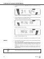
Possible indications:
“D1”: The recording has been completed, the display indicates dropout no. 1.
“MIN RF”: The recording has been completed, no dropout has been detected. The display
indicates the minimum RF level measured.
“OVFL”: The recording has been stopped automatically because six dropouts have been detected already or because the available time (16 minutes) has elapsed.
WMS 470
39
6 Advanced Functions (EXTRA Menu)
• To retrieve the other results press or briefly. Dropouts are indicated like this (Example 1):
Example 1: Dropout no. 1 occurred after 124 seconds.
• The first storage locations are assigned to dropouts, the last two for the lowest RF level
and highest audio level measured (Examples 2 and 3).
Example 2: Minimum RF level: -85 dB
Example 3: Maximum audio level: -5 dB
• The last item in the result list is followed (the first item preceded) by the "EXIT" option.
SQUELCH
• If the receiver finds no clean frequency, check your antenna setup (cable lengths, booster,
power splitter, system wiring).
• If this is correct and there is still a stable RF noise floor you can try to increase the
squelch threshold slowly from -100 dBm to -86 dBm to avoid noise when the RF signal
is weak. Make sure never to set the squelch threshold any higher than absolutely necessary.
The adjustable squelch will mute the receiver if the received signal is too weak so the
related noise or the self-noise of the receiver will not become audible while the transmitter is off the air.
• The higher the squelch threshold (-86 dB = max., -100 dB = min.), the lower the sensitivity of the receiver and thus the usable range between transmitter and receiver.
Note
40
WMS 470
6 Advanced Functions (EXTRA Menu)
Pilot Tone
As long as this function is active, the received signal contains a continuous signal at a predefined frequency (a pilot tone). If the receiver detects no pilot tone, the receiver's audio
output will be muted.
• The HT 400, HT 450, PT 400, and PT 450 transmit no pilot tone. If you use the receiver
together with these transmitters, we recommend deactivating the pilot tone.
Note
• To reset all parameters to their factory default settings, use the "FACTORY RESET"
screen.
FACTORY RESET
The INFO screen lets you call up information about your receiver:
- j"V1.1": firmware version
- "B 4--.50": frequency band
- "PV 1.0": Preset version
- "INTRO": This screen allows you to edit the name displayed upon switching power to the
receiver ON. (The default setting is "AKG PROFESSIONAL".)
INFO
The "INTRO" submenu lets you enter and save a new name at any time.
You can select any combination of up to 16 letters and numerals.
INTRO
1. Select the "INTRO" screen.
The first character starts flashing.
2. Use the arrow keys to select the desired characters.
WMS 470
41
7 Microphone Technique
Handheld Transmitter
A handheld vocal microphone provides many ways of shaping the sound of your voice as it
is heard over the sound system.
The following sections contain useful hints on how to use your handheld transmitter for best
results.
Working Distance and
Proximity Effect
Refer to fig. 13 on page vi.
Basically, your voice will sound the bigger and mellower, the closer you hold the microphone
to your lips. Moving away from the microphone will produce a more reverberant, more distant sound, as the microphone will pick more of the room’s reverberation.
You can use this effect to make your voice sound aggressive, neutral, insinuating, etc. simply by changing your working distance.
Proximity effect is a more or less dramatic boost of low frequencies that occurs when you
sing into the microphone from less than 2 inches. It gives more "body" to your voice and an
intimate, bass-heavy sound.
Angle of Incidence
Refer to fig. 13 on page vi.
Sing to one side of the microphone or above and across the microphone’s top. This provides
a well-balanced, natural sound.
If you sing directly into the microphone, it will not only pick up excessive breath noise but
also overemphasize "sss", "sh", "tch", "p", and "t" sounds.
Feedback
Refer to fig. 14 on page vi.
Feedback is the result of part of the sound projected by a speaker being picked up by a microphone, fed to the amplifier, and projected again by the speaker. Above a specific volume
or "system gain" setting called the feedback threshold, the signal starts being regenerated
indefinitely, making the sound system howl and the sound engineer desperately dive for the
master fader to reduce the volume and stop the howling.
To increase usable gain before feedback, place the main ("FOH") speakers in front of the microphones (along the front edge of the stage).
If you use monitor speakers, be sure never to point any microphone directly at the monitors.
Feedback may also be triggered by resonances depending on the acoustics of the room or
hall. With resonances at low frequencies, proximity effect may cause feedback. In this case,
it is often enough to move away from the microphone a little to stop the feedback.
Backing Choir
Refer to fig. 15 on page vi.
1. Never let more than two persons share a microphone.
2. Ask your backing vocalists never to sing more than 35 degrees off the microphone axis.
The microphone is very insensitive to off-axis sounds. If the two vocalists were to sing
into the microphone from a wider angle than 35 degrees, you may end up bringing up
the fader of the microphone channel far enough to create a feedback problem.
PB 1000 (HT 470 C5 only)
The PB 1000 Presence Boost Adapter (installed in the HT 470 C5 handheld transmitter)
boosts the sensitivity of the microphone element by approx. 5 dB between 5 kHz and 9 kHz
for optimum intelligibility of speech.
PPC 1000 (HT 470 C5 only)
The PPC 1000 Polar Pattern Converter (optional accessory for the HT 470 C5) will change
the microphone's pickup pattern from cardioid to hypercardioid. This makes the microphone
even less sensitive to sounds arriving from the sides, resulting in higher gain before feedback when you use monitor speakers on stage.
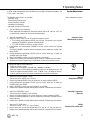
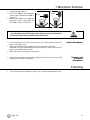
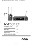
• To install the PPC 1000, you need to remove the PB 1000 Presence Boost Adapter
first.
Note
42
WMS 470
7 Microphone Technique
a
1. Unscrew the wire-mesh cap.
2. Pull the PB 1000 off the microphone
capsule, slowly rotating the PB 1000 as PB 1000
you pull (a).
3. Slide the PPC 1000 on the microphone
capsule to the stop, slowly rotating the
PPC 1000 as you push it home (b).
b
PPC 1000
• When installing or removing the PPC 1000/PB 1000, make sure to grip the capsule and rubber shock mount (arrows) firmly with your thumb and forefinger to
prevent the capsule being severed from the shock mount.
CAUTION
1. Fix the microphone on the H 40/1 lavalier clip or H 41/1 tiepin referring to the microphone’s instruction manual.
2. Clamp the microphone on your clothing as close as possible to your mouth.
Remember that gain-before-feedback will be the higher the shorter the distance between the microphone and the mouth!
3. Make sure to aim the microphone at your mouth.
Lavalier Microphones
• Refer to the user manual of the respective microphone for instructions on how to use AKG
headworn and instrument microphones.
Headworn and
Instrument
Microphones
8 Cleaning
• To clean the transmitter and receiver surfaces, use a soft cloth moistened with water.
WMS 470
43
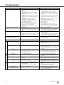
9 Troubleshooting
Problem
No sound.
Possible Cause
1.
2.
3.
4.
5.
6.
7.
8.
9.
10.
11.
12.
13.
Noise, crackling, unwanted signals.
1.
2.
Distortion.
Momentary loss of sound ("dropouts") at
some points within performance area.
Remedy
1.
Connect AC adapter to receiver and/or power outlet.
2.
3.
4.
Push POWER switch to switch receiver ON.
Connect receiver output to mixer or amplifier input.
Connect microphone or instrument to audio input on
bodypack.
Tune transmitter and receiver to the same frequency.
5.
6.
7.
8.
9.
10.
11.
12.
13.
Relocate receiver or antennas.
Switch off interference sources or defective appliances or tune transmitter and receiver to a different
frequency; have electrical installation checked.
1.
GAIN control on transmitter is set too high or too low. 1.
2.
Interference from other wireless systems, TV, radio, 2.
CB radios, or defective electrical appliances or installations.
Decrease or increase GAIN setting just enough to
stop the distortion.
Switch off interference sources or defective appliances or tune transmitter and receiver to a different
frequency; have electrical installation checked.
•
Antenna location.
•
Frequency settings cannot be changed.
•
Relocate receiver or antennas. If dead spots persist,
mark and avoid them.
1.
Switch power to receiver OFF and back ON after
about 10 seconds.
If problem persists, contact your AKG Service Center.
Problem
Remedy
Transmitter only
Receiver and transmitter
Receiver only
2.
44
Switch transmitter "ON" or set MUTE switch to ”ON”
position.
Insert batteries conforming to "+" and "-" marks.
Replace batteries/charge battery pack.
Move closer to receiver or choose lower squelch
threshold setting.
Remove obstructions.
Avoid spots where you cannot see receiver.
Remove offending objects or move receiver away.
Check Preset versions on transmitter and receiver.
1.
2.
Error Messages
ERR.>SYS<
AC adapter is not connected to receiver and/or power
outlet.
Receiver is OFF.
Receiver is not connected to mixer or amplifier.
Microphone or instrument is not connected to bodypack transmitter.
Transmitter is tuned to different frequency than receiver.
Transmitter is "OFF" or transmitter MUTE switch at
"MUTE".
Transmitter batteries are not inserted properly.
Transmitter batteries/battery pack dead.
Transmitter is too far away from receiver or squelch
threshold setting is too high.
Obstructions between transmitter and receiver.
Receiver is invisible from transmitter location.
Receiver too close to metal objects.
Transmitter and receiver Preset versions are not
identical.
Antenna location.
Interference from other wireless systems, TV, radio,
CB radios, or defective electrical appliances or installations.
ERR.>PRE<
•
Error in selected Preset.
1.
2.
3.
TXBand
1.
Transmitter frequency band is not identical with receiver frequency band.
RF output too high/low.
1.
2.
ERR.>USR<
•
Last setting cannot be loaded.
1.
2.
Set frequency and squelch threshold again.
If problem occurs frequently, contact your AKG Service Center.
ERR.>RF<
•
PLL error. (Receiver cannot lock on to selected frequency.)
1.
2.
Set different frequency.
If problem persists, contact your AKG Service Center.
Err.>IR<
•
Infrared transmisison failed.
•
>-h<
1.
Transmitter cannot identify battery as dry or
rechargeable type.
Transmitter was switched on during charging.
1.
2.
•
Battery is not fully charged.
1.
2.
Point transmitter infrared sensor directly at receiver
infrared emitter from a distance of approx. 2 inches
(5 cm).
Remove battery and reinsert after approx. five seconds.
Remove transmitter from charger, switch off, and
restart charging (cf. CU 400 manual)
Charge transmitter using CU 400 charger.
Replace transmitter battery with new dry or fully
charged rechargeable battery.
>ChArGE<
(rechargeable battery only)
2.
2.
Continue with previous Preset.
Select error-free Preset.
If problem occurs frequently, contact your AKG Service Center.
Use transmitter with the same frequency band as the
receiver.
Use transmitter with lower/higher Rf output.
WMS 470
10 Specifications
System
RF carrier frequency ranges:
Band 1: 650.1 – 680 MHz
Band 3: 720 – 750 MHz
Band 3-K: 740.1 – 751.9 MHz
Band 5-A: 790 – 821.5 MHz
Band 5-B: 806.125 – 809.750 MHz
Band 5-D: 794.1 – 805.9 MHz
Band 6-A-ISM: 835.1 – 861.9 MHz and 863.1 – 864.9 MHz (ISM)
Band 7: 500.1 – 530.5 MHz
Band 8: 570.1 – 600.5 MHz
Band 9-U: 600 – 630.5 MHz
Band 9: 600 – 605.9 MHz and 614.1 – 630.5 MHz
Receiver
Switching bandwidth:
Modulation:
Sensitivity:
Receiver type:
Diversity system:
Audio bandwidth:
THD at 1 kHz:
Signal-to-noise:
Audio outputs:
Audio output level:
Antenna inputs:
Transmitter battery indication:
Power supply:
Dimensions:
Weight:
30.5 MHz (depending on local regulations)
FM
6 dBμV / -100 dBm
Super heterodyne
μC controlled space diversity
35 to 20,000 Hz
<0.3%
120 dB(A)
balanced XLR, switchable to -30 or 0 dBm
unbalanced TS 1/4" jack
+9 dBu (max.)
2x 50-ohm BNC female connectors
low battery
12 V / 500 mA DC
200 x 44 x 190 mm (7.8 x 1.7 x 7.4 in.)
972 g (2.2 lbs.)
Handheld Transmitter
Switching bandwidth:
Modulation:
RF output power:
Spurious:
Antenna:
Audio bandwidth:
THD:
S/N ratio (A-weighted):
Microphone element:
Max. SPL:
Battery life:
Size:
Net Weight:
30.5 MHz (depending on local regulations)
FM
10, 30, or 50 mW (ERP max., depending on local regulations)
≤ 70 dBc
Built-in dipole antenna
35 to 20,000 Hz
<0.7% typical at rated deviation/1 kHz
120 dB(A)
HT 470 D5: dynamic microphone (supercardioid)
HT 470 C5: condenser microphone (cardioid)
HT 470 D5: ≤ 140 dB SPL
HT 470 C5: ≤ 140 dB SPL
≥ 7 hours (1x LR6 AA-size battery)
≥ 8 hours (1x AA-size NiMH >2100 mAh rechargeable battery)
≥ 14 hours (1x FR6 AA-size lithium battery)
229 x 52.5 mm max. dia. (9 x 2 in.)
220 g (7.8 oz.)
Bodypack Transmitter
Switching bandwidth:
Modulation:
RF output power:
Spurious:
Antenna:
Audio bandwidth:
THD:
S/N Ratio (A-weighted)
Audio input:
Battery life:
Size:
Net weight:
30.5 MHz (depending on local regulations)
FM
10, 30 or 50 mW (ERP max., depending on local regulations)
≤ 70 dBc
¼- wave antenna
35 to 20,000 Hz
<0.7% typical at rated deviation/1 kHz
120 dB(A)
TB3M 3-pin mini XLR socket (3.1 Vrms max.)
≥ 7 hours (1x LR6 AA-size battery)
≥ 8 hours (1x AA-size NiMH >2100 mAh rechargeable battery)
≥ 14 hours (1x FR6 AA-size lithium battery)
60 x 73,5 x 30 mm (2.4 x 2.9 x 1.2 in.)
90 g (3.2 oz.)
This equipment conforms to the standards listed in the Declaration of Conformity. To order a free copy of the Declaration of Conformity, visit
http://www.akg.com or contact [email protected].
WMS 470
45
Microphones · Headphones · Wireless Microphones · Wireless Headphones · Headsets · Electroacoustical Components
Mikrofone · Kopfhörer · Drahtlosmikrofone · Drahtloskopfhörer · Kopfsprechgarnituren · Akustische Komponenten
Microphones · Casques HiFi · Microphones sans fil · Casques sans fil · Micros-casques · Composants acoustiques
Micrófonos · Auriculares · Micrófonos inalámbricos · Auriculares inalámbricos · Auriculares con micrófono · Componentes acústicos
AKG Acoustics GmbH
Lemböckgasse 21–25, A-1230 Vienna/AUSTRIA, phone: (+43-1) 86654-0*
e-mail: [email protected]
For other products and distributors worldwide visit www.akg.com
Technische Änderungen vorbehalten. Specifications subject to change without notice. Ces caractéristiques sont susceptibles de modifications.
Ci riserviamo il diritto di effettuare modifiche tecniche. Nos reservamos el derecho de introducir modificaciones técnicas.
Especificações sujeitas a mudanças sem aviso prévio.
Printed in China (P.R.C.).
01/11/9100 U 13350