1
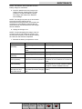
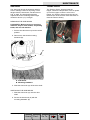
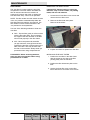
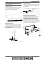
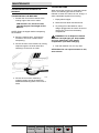
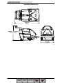
S10
(Electric)
Sweeper
English EN
Operator Manual
9007293
Rev. 03 (2-2010)
*997293*
www.tennantco.com
Home
Find...
Go To..
This manual is furnished with each new model. It provides necessary operation and maintenance instructions.
Read this manual completely and understand the machine before operating or servicing it.
This machine will provide excellent service. However, the best results will be obtained at minimum costs if:
S The machine is operated with reasonable care.
S The machine is maintained regularly - per the machine maintenance instructions provided.
S The machine is maintained with manufacturer supplied or equivalent parts.
PROTECT THE ENVIRONMENT
Please dispose of packaging materials,
old machine components such as
batteries, hazardous fluids such as
antifreeze and oil, in an
environmentally safe way according to
local waste disposal regulations.
Always remember to recycle.
MACHINE DATA
Please fill out at time of installation for future reference.
Model No. -Serial No. -Machine Options -Sales Rep. -Sales Rep. phone no. -Customer Number -Installation Date -Tennant N.V.
Industrielaan 6 5405 AB
P.O. Box 6 5400 AA Uden--Alankomaat
[email protected]
www.tennantco.com
Specifications and parts are subject to change without notice.
Original instructions, copyright E 2010 TENNANT Company, Printed in The Netherlands. All rights reserved
DECLARATION OF CONFORMITY FOR MACHINERY
(according to Annex II A of the Machinery Directive)
TENNANT N.V.
Herewith declares, on our own responsibility, that the machinery
Industrielaan 6 5405 AB
P.O. Box 6 5400 AA
Uden -- The Netherlands
Uden, 21--05--2010
S10
-- is in conformity with the provisions of the Machinery Directive (2006/42/EC), as amended and with national
implementing legislation
-- is in conformity with the provisions of the Electro Magnetic Compatibility Directive 2004/108/EC
-- is in conformity with the provisions concerning noise emission for outdoor use (Directive 2000/14/CE) and
with national implementing legislation
EN
and that
-- the following harmonized standards or parts of these standards have been applied: EN ISO 14121--1, EN
1037, EN 60335--1, EN 60204--1, EN ISO 13849--1, EN ISO 13849--2, EN 60529, EN ISO 4413, EN 349, EN
55012, EN 61000--6--2, EN ISO 11201, EN ISO 4871, EN ISO 3744*, EN ISO 13059*, EN ISO 3450, EN
60335--2--72.
-- the following national standards or parts of these standards have been used:
CONTENTS
CONTENTS
Page
SAFETY PRECAUTIONS . . . . . . . . . . . . . . . . . 2
OPERATION . . . . . . . . . . . . . . . . . . . . . . . . . . . . 4
MACHINE COMPONENTS . . . . . . . . . . . . . 4
SYMBOL DEFINITIONS . . . . . . . . . . . . . . . . 5
CONTROLS AND INSTRUMENTS . . . . . . 6
OPERATION OF CONTROLS . . . . . . . . . . 7
PROPEL CONTROL HANDLES . . . . . . . . . 7
FILTER SHAKER OVERRIDE SWITCH . . 7
BATTERY CHARGE INDICATOR . . . . . . . . 8
BATTERY CHARGER PANEL . . . . . . . . . . . 8
HOUR METER . . . . . . . . . . . . . . . . . . . . . . . . 9
MAIN BRUSH LEVER . . . . . . . . . . . . . . . . . . 9
SIDE BRUSH ARM . . . . . . . . . . . . . . . . . . . . 10
PARKING BRAKE LEVER . . . . . . . . . . . . . . 10
CIRCUIT BREAKERS AND FUSES . . . . . . 11
BRUSH INFORMATION . . . . . . . . . . . . . . . . 11
MACHINE OPERATION . . . . . . . . . . . . . . . . 12
PRE--OPERATION CHECKLIST . . . . . . . . . 12
OPERATION ON GRADES . . . . . . . . . . . . . 12
SWEEPING . . . . . . . . . . . . . . . . . . . . . . . . . . 12
EMPTYING THE HOPPER . . . . . . . . . . . . . 13
REMOVING THE HOPPER . . . . . . . . . . . . . 14
MACHINE TROUBLESHOOTING . . . . . . . 15
Page
MAINTENANCE . . . . . . . . . . . . . . . . . . . . . . . . . 16
MAINTENANCE CHART . . . . . . . . . . . . . . . 16
BATTERIES . . . . . . . . . . . . . . . . . . . . . . . . . . 17
LEAD ACID BATTERIES . . . . . . . . . . . . . . . 17
CHARGING BATTERIES . . . . . . . . . . . . . . . 18
BRUSHES . . . . . . . . . . . . . . . . . . . . . . . . . . . . 20
MAIN BRUSH . . . . . . . . . . . . . . . . . . . . . . . . . 20
REMOVING THE MAIN BRUSH . . . . . . . . . 20
INSTALLING THE MAIN BRUSH . . . . . . . . 20
SIDE BRUSH . . . . . . . . . . . . . . . . . . . . . . . . . 21
REMOVING THE SIDE BRUSH . . . . . . . . . 21
IINSTALLING THE SIDE BRUSH . . . . . . . . 21
THERMO-SENTRY . . . . . . . . . . . . . . . . . . . . 21
DUST FILTER . . . . . . . . . . . . . . . . . . . . . . . . 22
REMOVING THE DUST FILTER . . . . . . . . 22
INSTALLING THE DUST FILTER . . . . . . . . 22
SKIRTS AND SEALS . . . . . . . . . . . . . . . . . . 23
HOPPER LIP SKIRT . . . . . . . . . . . . . . . . . . . 23
REAR BRUSH SKIRTS . . . . . . . . . . . . . . . . 23
HOPPER TOP SEAL . . . . . . . . . . . . . . . . . . 23
MAIN BRUSH SKIRTS AND SEALS . . . . . 23
TRANSPORTING AND STORING
THE MACHINE . . . . . . . . . . . . . . . . . . . . . 24
TRANSPORTING THE MACHINE . . . . . . . 24
STORING MACHINE . . . . . . . . . . . . . . . . . . 24
SPECIFICATIONS . . . . . . . . . . . . . . . . . . . . . . . 25
GENERAL MACHINE DIMENSIONS/
CAPACITIES . . . . . . . . . . . . . . . . . . . . . . . 25
GENERAL MACHINE PERFORMANCE . . 25
MACHINE DIMENSIONS . . . . . . . . . . . . . . . 26
1
S10 9007293 (2--10)
Home
Find...
Go To..
GENERAL INFORMATION
SAFETY PRECAUTIONS
The following symbols are used throughout this
manual as indicated in their description:
WARNING: To warn of hazards or
unsafe practices that could result in
severe personal injury or death.
FOR SAFETY: To identify actions that
must be followed for safe operation of
equipment.
The following information signals potentially
dangerous conditions to the operator or
equipment. Read this manual carefully. Know
when these conditions can exist. Locate all
safety devices on the machine. Then, take
necessary steps to train machine operating
personnel. Report machine damage or faulty
operation immediately. Do not use the machine
if it is not in proper operating condition.
WARNING: Batteries emit hydrogen
gas. Explosion or fire can result. Keep
sparks and open flame away. Keep
covers open when charging.
WARNING: Disconnect battery cables
and charger plug before servicing
machine. Do not charge batteries with
damaged power supply cord. Do not
modify plug.
If the charger supply cord is damaged or
broken, it must be replaced by the
manufacturer or its service agent or a
similarly qualified person in order to avoid a
hazard.
WARNING: Heavy hopper. Do not
remove without help. Can cause back
strain.
This machine is not equipped with
explosion proof motors. The electric motors
will spark upon start up and during
operation which could cause a flash fire or
explosion if machine is used in an area
where flammable vapors/liquids or
combustible dusts are present.
FOR SAFETY:
1. Do Not Operate Machine:
-- Unless Trained And Authorized.
-- Unless Operation Manual Is Read
And Understood.
-- In Flammable Or Explosive Areas
Unless Designed For Use In Those
Areas.
-- Do Not Pick Up Flammable Or Toxic
Material, Burning Or Smoking
Debris, Or Hazardous Dust
2. Before Starting Machine:
-- Make Sure All Safety Devices Are In
Place And Operate Properly.
3. When Using Machine:
-- Go Slow On Grades And Slippery
Surfaces.
-- Use Care When Backing Machine.
-- Do Not Operate On Inclines That
Exceed 8.75% (5º) With A Full
Hopper, Never Operate On Inclines
That Exceed 12.2% (7º)
4. Before Leaving Or Servicing Machine:
-- Stop On Level Surface.
-- Set Parking Brake.
-- Turn Off Machine And Remove Key.
5. When Servicing Machine:
-- Avoid Moving Parts. Do Not Wear
Loose Jackets, Shirts, Or Sleeves
When Working On Machine.
-- Use Hoist Or Jack Of Adequate
Capacity To Lift Machine.
-- Wear Eye And Ear Protection When
Using Pressurized Air Or Water.
-- Disconnect Battery Connections
Before Working On Machine.
-- Avoid Contact With Battery Acid.
-- Use TENNANT Supplied Or
Equivalent Replacement Parts.
6. When loading/unloading machine
onto/off truck or trailer.
-- Turn off machine.
-- Use truck or trailer that will support
the weight of the machine.
-- Block machine tires.
-- Tie machine down to truck or trailer.
2
S10 9007293 (2--10)
Home
Find...
Go To..
GENERAL INFORMATION
The following safety decals are mounted on the
machine in the locations indicated. If these, or
any decal becomes damaged or illegible, install
a new decal in its place.
FOR SAFETY LABEL -LOCATED ON THE
CONTROL PANEL.
CHARGER CORD LABEL -LOCATED NEAR CHARGER.
BACK STRAIN LABEL -LOCATED ON THE TOP
OF THE HOPPER.
BATTERY CHARGING LABEL -LOCATED ON THE LEFT SIDE
PANEL.
3
S10 9007293 (2--10)
Home
Find...
Go To..
OPERATION
OPERATION
MACHINE COMPONENTS
A
B
C
D
H
G
A.
B.
C.
D.
E.
F.
G.
H.
F
E
Filter Cover
Left Access Cover
Parking Brake Lever
Hopper
Side Brush
Side Brush Arm
Right Access Cover
Instrument Panel
4
S10 9007293 (2--10)
Home
Find...
Go To..
OPERATION
SYMBOL DEFINITIONS
The symbols are used to identify controls and
displays on the machine:
Filter Shaker
Main Brush Free-Float
Main Brush Down
Main Brush Up
Main Brush Adjust
Circuit Breaker
Circuit Breaker
Hour Meter
Battery Charge Indicator
Electric Key Switch
Key Switch Off
Key Switch On
5
S10 9007293 (2--10)
Home
Find...
Go To..
OPERATION
CONTROLS AND INSTRUMENTS
E
D
C
B
I
H
G
F
A
J
A.
B.
C.
D.
E.
F.
G.
H.
I.
J.
Stationary Handle
Filter Shaker Override Switch
Battery Charge Indicator
Main Brush Lever
Hour Meter
On-Off Key Switch
Forward Propel Handle
Reverse Propel Handle
Circuit Breakers
Charger Panel
6
S10 9007293 (2--10)
Home
Find...
Go To..
OPERATION
FILTER SHAKER OVERRIDE SWITCH
OPERATION OF CONTROLS
PROPEL CONTROL HANDLES
The propel control handles control the direction
of the machine.
The filter shaker override switch enables the
automatic filter shaker. When the switch is in the
“on” position, the filter shaker motor will shake
the dust from the filter for 20 seconds when the
machine is turned off. The switch should be in
the “on” position during normal operation.
To move the machine forward, wrap the fingers
around the stationary handle, then press the
palms of the hand against the propel handle. To
stop the machine, release the handle.
When the switch is in the “off” position, the filter
shaker motor will not operate when the machine
is turned off. The switch should be in the “off”
position when servicing the machine.
To move the machine backward, squeeze the
reverse propel handle. To stop the machine,
release the handle.
7
S10 9007293 (2--10)
Home
Find...
Go To..
OPERATION
When the red light lights up, the machine will
completely shut down.
BATTERY CHARGE INDICATOR
The battery discharge indicator shows the
charge level of the batteries.
When the batteries are fully charged, all seven
lights are lit.
As the batteries discharge, the lights go out until
only the left light is blinking. Sweeping functions
will continue. Recharge the batteries when only
the left light is blinking.
NOTE: Do not charge batteries more often than
necessary. Excessive charging could reduce the
life of the batteries. It is best to charge the
batteries only when the left light indicates that
the battery needs charging. See BATTERIES in
the MAINTENANCE section.
NOTE: The blinking left battery discharge light
will not reset from blinking until the batteries are
fully charged.
BATTERY CHARGER PANEL
The battery charger panel shows the status of
charging after the charger has been plugged
into a wall outlet.
8
S10 9007293 (2--10)
Home
Find...
Go To..
OPERATION
HOUR METER
The hour meter records the number of hours the
machine has operated. This information is
useful in determining when to service the
machine.
Main brush down position: (Smooth even floors)
Push the lever forward and then pull it back and
lock the top notch in the lever in the Main Brush
Down position.
Main brush free--float position: (Uneven floors)
Push the lever forward and then to the left and
release it in the Main Brush Free-Float position.
MAIN BRUSH LEVER
The main brush lever controls the position of the
main brush.
Main brush up position: Pull the lever up and
lock the bottom notch of the lever into the Main
Brush Up position.
When parking the machine, always raise the
brush to prevent the bristles from taking a set.
9
S10 9007293 (2--10)
Home
Find...
Go To..
OPERATION
SIDE BRUSH ARM
PARKING BRAKE LEVER
The side brush arm controls the position of the
side brush.
To set the parking brake, step on the lever and
release it into the long notch on the left.
To raise the side brush, pull the lift arm up and
push it back into the raised position. To lower
the side brush, pull the arm forward and release
it into the down position.
To release the parking brake, step on the lever
and release it into the short notch on the right.
When parking the machine, always raise the
brush to prevent the brush bristles from taking a
set.
10
S10 9007293 (2--10)
Home
Find...
Go To..
OPERATION
CIRCUIT BREAKERS AND FUSES
Circuit breakers are resettable electrical circuit
protection devices that stop the flow of current
in the event of a circuit overload. Once a circuit
breaker has tripped, allow breaker to cool and
then press the reset button to manually reset
the breaker.
BRUSH INFORMATION
For best results, use the correct brush type for
the cleaning application. Listed below are the
brushes and the applications for which each is
best suited.
NOTE: The amount and type of soilage play an
important role in determining the type of
brushes to use. Contact a Tennant
representative for specific recommendations.
Nylon 6-Double Row Main Brush -Recommended for general sweeping, and has
good hopper loading. Nylon has the longest life
of the bristle types. Use this brush for sweeping
rough or irregular surfaces.
The fuse is a one-time protection device
designed to stop the flow of current in the event
of a circuit overload. The 15 A fuse is located
behind the hopper on the main frame.
NOTE: Always replace the fuse with a fuse of
the same type and amperage.
The following chart shows the various circuit
breakers and fuses and the electrical
components they protect.
Fiber and Wire 6-Row Main Brush -- Offers
good sweeping action and pickup in heavy dust
concentrations. This brush is recommended
where soilage is slightly encrusted. The brush is
not recommended for heavy buildup or hard
packed soilage.
Natural Fiber 18- Row Main Brush -- The
natural choice for cleaning fine debris on carpet
and sweeping very heavy dust and other fine
particles on hard surfaces.
PROTECTIVE
DEVICE
RATING
PROTECTED
CIRCUIT
CB--1
CB--2
FU--1
Shaker Motor
Main Drive (Propel) Motor
Control Power
15 A
60 A
15 A
Polypropylene 6-Double Row Main Brush -Superior pick-up of sand, gravel, and paper
litter. Polypropylene retains its stiffness when
wet and can be used indoors or outdoors with
equal performance. Not recommended for
high-temperature debris.
11
S10 9007293 (2--10)
Home
Find...
Go To..
OPERATION
SWEEPING
MACHINE OPERATION
PRE--OPERATION CHECKLIST
- Check the battery charge level.
- Check the hopper lip skirt for damage and
wear.
- Check the hopper seal for damage and
wear.
Plan the sweeping in advance. Try to arrange
long runs with minimum stopping and starting.
Overlap brush paths. Sweep as straight a path
as possible. Avoid bumping into posts or
scraping the sides of the sweeper. Sweep
debris from very narrow aisles into main aisles
ahead of time. Do an entire floor or section at
one time.
Pick up oversize debris before sweeping. Pick
up pieces of wire, twine, or string, which could
become entangled in brush or brush plugs.
- Check the dust filter for damage.
- Check the condition of the main brush.
Remove any string, banding, plastic wrap,
or other debris wrapped around the brush.
1. Turn the on--off switch key to the on
position.
- Check the main brush and rear brush skirts
for damage, wear, and clearance.
- Side Brush Option: Check the condition of
the side brush. Remove any string, banding,
plastic wrap, or other debris wrapped
around the brush.
- Check the service records to determine
maintenance requirements.
OPERATION ON GRADES
Drive the machine slowly on grades. The
maximum rated climb angle is 7_ or 12.2%.
FOR SAFETY: When Using Machine; Go
Slow On Grades And Slippery Surfaces.
2. Release the machine parking brake, if
equipped.
3. Move the main brush lever into the (Main
Brush Down) or (Main Brush Free-Float)
position.
4. Move the side brush arm into the down
position.
5. Sweep as required.
6. Raise the main brush and side brush.
12
S10 9007293 (2--10)
Home
Find...
Go To..
OPERATION
7. Turn the on-off switch key to the left.
Remove the key from the on-off switch.
5. Swing the dump lever (B) under the hook
(C); Lift the dump lever to dump the
hopper (A).
B
C
A
FOR SAFETY: Before leaving or servicing
machine; stop on level surface, set parking
brake, and turn off machine.
EMPTYING THE HOPPER
A. Hopper
B. Dump Lever
C. Lever Hook
03142
6. Engage the lever hook (not shown) to
keep the hopper in the “dump” position.
1. Pull the main brush lever into the (Main
Brush Up) position.
2. Pull the side brush arm into the raised
position.
3. Slowly drive the machine up to the dump
site. Turn off the machine. The filter will
operate for approximately 20 seconds.
NOTE: The filter shaker override switch must be
in the “on” position to automatically shake the
dust filter when the machine is turned off.
FOR SAFETY: Before leaving or servicing
machine; stop on level surface, set parking
brake, and turn off machine.
7. Slowly back the machine away from the
dump site or remove the hopper from the
machine to empty the contents from the
hopper.
NOTE:See REMOVING THE HOPPER in the
following section if it is necessary to remove the
hopper from the machine to empty the hopper.
8. Release the lever hook (not shown), lower
the hopper, and return the dump lever to
its storage location.
9. Lower the filter cover.
4. Lift the filter cover.
13
S10 9007293 (2--10)
Home
Find...
Go To..
OPERATION
6. Reinstall the hopper into the machine.
Make sure the hooks on hopper are
completely installed onto the machine.
REMOVING THE HOPPER
1. Pull the main brush lever into the (Main
Brush Up) position.
2. Pull the side brush arm into the raised
position.
3. Turn off the machine. The filter will operate
for approximately 20 seconds.
NOTE: The filter shaker override switch must be
in the “on” position to automatically shake the
dust filter when the machine is turned off.
FOR SAFETY: Before leaving or servicing
machine; stop on level surface, set parking
brake, and turn off machine.
4. Lift the filter cover.
7. Close the filter cover.
5. Seek assistance to remove the hopper
from the machine. Lift the hopper out of
the machine.
WARNING: Heavy hopper. Do not
remove without help. Can cause back
strain.
14
S10 9007293 (2--10)
Home
Find...
Go To..
OPERATION
MACHINE TROUBLESHOOTING
Problem
Cause
Remedy
Excessive dusting
g
Dust skirts and seals worn,,
damaged, not adjusted properly
Replace
p
or adjust
j
skirts or seals
Dust filter clogged
Shake and/or clean or replace filter
Vacuum hose damaged
Replace vacuum hose
Vacuum fan belt slipping or broken
Adjust or replace belt
Brush bristles worn
Replace brushes
Brushes not adjusted properly
Adjust brushes
Brushes not installed properly
Reinstall brushes
Debris caught
g in brush drive
mechanism
Free mechanism of debris
Hopper full
Empty hopper
Hopper floor skirts worn, damaged
Replace skirts
Brush belt slipping, or broken
Replace belt
Charger
g not plugged
p gg into electrical
receptacle
Plug
g charger
g into electrical
receptacle
Charger cord not completely
plugged into bottom of charger
Replug charger cord into charger
Charger cord is damaged
Replace charger cord
Poor sweeping
performance
f
Battery
y charger
g not
operating
15
S10 9007293 (2--10)
Home
Find...
Go To..
MAINTENANCE
MAINTENANCE
2
5
1
4
3
1
MAINTENANCE CHART
Interval
Daily
25 Hours
Key
Description
1
Brush skirts
2
3
4
Main brush
Side brush
Hopper
5
Battery cells
Procedure
Check for damage, wear, and
floor clearance
Check for damage, wear, debris
Check for damage, wear, debris
Check seals for damage and
wear
Check electrolyte level
No. of
Lubricant/ Service
Fluid
Points
-5
----
1
1
3
DW
2
LUBRICANT/FLUID
DW -- Distilled water
16
S10 9007293 (2--10)
Home
Find...
Go To..
MAINTENANCE
LEAD ACID BATTERIES
BATTERIES
The batteries are designed to hold their power
for long periods of time. The lifetime of the
batteries is limited to number of charges the
batteries receive. To get the most life from the
batteries, recharge them immediately when the
battery discharge indicator begins to blink.
Check the electrolyte level in each battery cell
before and after charging, and after every 25
hours of operation. Never add acid to the
batteries. Add distilled water only. Always keep
the battery caps on, except when adding water
or taking hydrometer readings.
FOR SAFETY: When servicing machine,
wear protective gloves when handling
batteries or battery cables. Avoid contact
with battery acid.
Objects made of metal can potentially short
circuit the batteries. Keep all metallic objects off
the batteries. Replace any worn or damaged
wires. Replace any defective batteries. To
dispose of batteries, contact a battery dealer or
your Tennant Service representative.
17
S10 9007293 (2--10)
Home
Find...
Go To..
MAINTENANCE
CHARGING BATTERIES
The following charging instructions are intended
for battery chargers supplied with the machine.
To prolong the life of the batteries only recharge
the batteries if the machine was used for a total
of 30 minutes or more. Do not leave batteries
discharged for lengthy periods.
WARNING: Fire Or Explosion Hazard.
Batteries emit hydrogen gas. Keep sparks
and open flame away. Keep battery
compartment open when charging.
1. Transport the machine to a well--ventilated
area for charging.
FOR SAFETY: Before leaving or servicing
machine; stop on level surface, set parking
brake, and turn off machine.
2. If charging wet (lead acid) batteries check
the fluid level before charging (See
BATTERY MAINTENANCE).
3. Remove the battery compartment covers
for ventilation when charging.
FOR SAFETY: When servicing batteries,
wear protective gloves and eye protection
when handling batteries and battery cables.
Avoid contact with battery acid.
4. Connect the charger cord into a properly
grounded electrical receptacle. The
charger will start automatically within a few
seconds. The LEDs will display the
charging state as described in the
following table.
Make sure the charger profile is properly set for
the battery type before charging. Failure to
properly set profile will result in battery damage.
To determine the battery type, see battery label.
Contact the battery supplier if not specified.
To verify the charger profile setting, connect the
charger cord into an electrical receptacle. If the
LED labeled “GEL” is on, the charger is set for
Gel (sealed) batteries. If the LED is off, the
charger is set for Wet/lead acid (flooded)
batteries.
CHARGING STATE LED DISPLAY
Charging
State
To change the charger profile, unplug the
charger, remove the “Charger Profile Selection”
panel, and position the switch towards the
proper setting, “GEL” or “Flooded” .
50% LED
75% LED
100% LED
0--50%
charged
Blinking
Off
Off
50--75%
charged
On
Blinking
Off
75--100%
charged
On
On
Blinking
100%
charged
On
On
On
Abnormal
Cycle*
Off
Off
Blinking
Fault detected *
Blinking
Blinking
Blinking
* See the On--board Battery Charger Fault Codes
table. When a fault occurs, the charger will also sound
an alarm.
18
S10 9007293 (2--10)
Home
Find...
Go To..
MAINTENANCE
NOTE: The machine will not operate once the
battery charger is connected.
5. Once the batteries are fully charged, the
charger will stop suppling power, but will
continue to monitor the battery voltage.
The charger will restart if the batteries
self--discharge.
NOTE: The charger may take up to 30 seconds
to turn off once the charger cord is
disconnected. During this time, the machine will
not power up. The charger cord must also be
disconnected for 30 seconds before the charger
can be restarted.
6. Unplug the charger cord.
NOTE: To avoid damaging the charger cord, do
not pull on the cord to unplug the charger from
the electrical receptacle. Use the plug to unplug
the cord from the electrical receptacle.
7. Reinstall the battery compartment covers.
LED FAULT CODE
FAULT
SOLUTION
3 LEDs blink once
repeatedly
Loose charger cable connection.
Check charger cable connection.
Loose or damaged battery
cable.
Check battery cable connections.
Defective Battery.
Replace battery.
3 LEDs blink twice
repeatedly
Input voltage is out of range.
Try using a different wall outlet.
3 LEDs blink three
times repeatedly
Safety thermostat exceeded
Open battery compartment to promote air
maximum internal temperature. circulation or move machine to a cooler climate.
3 LEDs blink four
times repeatedly
Output current exceeds a limit.
100% LED blinks
while the 50% and
75% LEDs are off.
Abnormal cycle. Safety timer
Battery maintenance required or replace
exceeded the 18 hour charging battery.
time.
Disconnect charger cord, wait 30 seconds,
then plug back in. If fault continues replace
charger or contact TENNANT Service.
19
S10 9007293 (2--10)
Home
Find...
Go To..
MAINTENANCE
INSTALLING THE MAIN BRUSH
BRUSHES
MAIN BRUSH
Inspect the main brush daily for wear or
damage. Remove any string or wire tangled on
the main brush, the main brush drive hub, or the
main brush idler hub.
REMOVING THE MAIN BRUSH
FOR SAFETY: Before leaving or servicing
machine; stop on level surface, set parking
brake, and turn off machine.
1. Place the main brush lift handle in the
(Main Brush Free-Float) position.
2. Open the main brush access door (D).
3. Pull the brush out of the brush
compartment.
NOTE: The hopper can be removed to aid
installing the main brush into the machine. See
REMOVING THE HOPPER in the OPERATION
section for proper procedure for removing the
hopper.
1. Slide the brush into the brush
compartment.
2. Rotate the brush until the slots on the
ends of the brush engage the keys on the
main brush drive hub (not shown).
NOTE: Do not force the main brush onto the
drive hub. When the main brush slots and drive
hub keys are properly aligned, the main brush
will easily engage the drive hub.
3. Close and secure the main brush access
door (D). Make sure the lift arm (B)
engages the idler lift arm pins (A).
D
A
B
C
A.
B.
C.
D.
20
Lift Arm Pins
Lift Arm
Idler Key
Access Door
02347
S10 9007293 (2--10)
Home
Find...
Go To..
MAINTENANCE
SIDE BRUSH
THERMO-SENTRY
The side brush should be inspected daily for
wear or damage. Remove any string or wire
tangled from the side brush, side brush drive
hub, or shaft. The side brush should be
replaced when the remaining bristle length
measures 25 mm (1 in) in length.
The Thermo--Sentry, located inside the
hopper, senses the temperature of the air pulled
up from the hopper. If there is a fire in the
hopper, the Thermo--Sentry stops the vacuum
fan and cuts off the air flow. Press the button to
reset the Thermo--Sentry.
REMOVING THE SIDE BRUSH
FOR SAFETY: Before leaving or servicing
machine; stop on level surface, set parking
brake, and turn off machine.
1. Pull the side brush arm up into the raised
position.
2. Remove the side brush mounting
hardware (B).
A
B
03144
A. Side Brush
B. Mounting Hardware
3. Slide the side brush (A) off the drive shaft.
IINSTALLING THE SIDE BRUSH
1. Slide the side brush (A) onto the drive
shaft.
2. Secure the side brush (A) with the
mounting hardware (B).
21
S10 9007293 (2--10)
Home
Find...
Go To..
MAINTENANCE
DUST FILTER
REMOVING THE DUST FILTER
The dust filter is located inside the dust filter
compartment. The filter shaker will shake the
filter for 20 seconds when the machine is
powered off. Inspect and clean or replace the
dust filter after every 100 hours of operation.
FOR SAFETY: Before leaving or servicing
machine; stop on level surface, set parking
brake, and turn off machine.
NOTE: The filter shaker override switch must be
in the “on” position to automatically shake the
dust filter when the machine is turned off. The
filter shaker override switch should be in the
“on” position for most operations.
1. Loosen the six front filter cover screws and
remove the front filter cover.
2. Remove the filter hold-down plate.
Remove the dust filter.
Use one of the following methods to clean the
dust filter:
D TAP -- Tap the filter gently on a flat surface
with the dirty side down. Do not damage
the edges of the filter element or the filter
will not seat properly in the filter frame.
D AIR -- Blow compressed air, 240 kPa
(35 psi) maximum, through the dust filter
opposite the direction of the arrows on the
side of the filter. This may be done with
the filter in the machine. Always wear eye
protection when using compressed air.
FOR SAFETY: When servicing machine,
wear eye and ear protection when using
pressurized air or water.
3. Inspect and clean or replace the dust filter.
INSTALLING THE DUST FILTER
1. Position the dust filter in the filter frame
with the arrows on the side of the filter
pointing away from the machine.
2. Position the filter hold-down plate on the
filter.
3. Secure the front filter cover on the filter
frame with the six front filter cover screws.
22
S10 9007293 (2--10)
Home
Find...
Go To..
MAINTENANCE
HOPPER TOP SEAL
SKIRTS AND SEALS
The hopper top seal is located on the front edge
of the machine frame. Inspect the seal for wear
or damage daily.
HOPPER LIP SKIRT
The hopper lip skirt is located on the lower rear
of the hopper. The hopper lip skirt should be
inspected for wear or damage daily.
02349
MAIN BRUSH SKIRTS AND SEALS
02348
The right side seal (not shown) is mounted to
the machine frame. The left side seal is
mounted to the main brush access door. The
main brush door seal is mounted to the door.
Inspect the seals for damage and wear daily.
The main brush skirts should clear the floor by 2
mm (0.06 in). Inspect the skirts for damage and
wear and proper floor clearance daily.
REAR BRUSH SKIRTS
The rear brush skirts are located on the bottom
rear of the brush compartment. The rear brush
skirts should clear the floor by 2 mm (0.06 in).
Inspect the skirt for wear or damage and proper
floor clearance daily.
02347
03157
23
S10 9007293 (2--10)
Home
Find...
Go To..
MAINTENANCE
STORING MACHINE
TRANSPORTING AND STORING THE
MACHINE
When storing the machine for extended periods
of time, the following procedures must be
followed to lessen the chance of rust, sludge, or
other undesirable deposits from forming.
TRANSPORTING THE MACHINE
1. Position the front of the machine at the
loading edge of the truck or trailer.
1. Empty debris hopper.
FOR SAFETY: Use Truck Or Trailer
That Will Support The Weight Of The
Machine.
NOTE: Empty the hopper before transporting
the machine.
2. Raise the main brush and side brush.
3. To prolong life of the batteries, leave
charger plugged into the outlet. Be sure to
remove the covers from the battery
compartment.
WARNING: Fire Or Explosion Hazard.
Batteries emit hydrogen gas. Keep sparks
and open flame away. Keep battery
compartment open when charging.
2. Block the machine tires. Tie down the
machine to the truck or trailer before
transporting.
3. Secure the front of the machine by routing
straps through the tie down holes and
fastening it to the truck or trailer.
4. Park the machine in a cool, dry area.
ATTENTION: Do not expose machine to rain,
store indoors.
03136
4. Secure the rear of the machine by
wrapping straps around the stationary
handle and fastening them to the truck or
trailer.
24
S10 9007293 (2--10)
Home
Find...
Go To..
SPECIFICATIONS
SPECIFICATIONS
GENERAL MACHINE DIMENSIONS/CAPACITIES
Item
Dimension/capacity
Length
1570 mm (62 in)
Height (maximum)
990 mm--1120 mm (39 in--44 in)
Width (with out side brush)
Sweeping path width (with side brush)
920 mm (36.25 in)
860 mm (34 in)
Hopper volume capacity
0.08 m# (2.8 cu ft)
Hopper weight capacity
68 kg (150 lb)
GVWR
345 kg (760 lb)
Operating sound level at operator ear
76 dB(A)
Vibration level at propel control handles
2.5 m/s@
GENERAL MACHINE PERFORMANCE
Item
Measure
Turning radius
1730 mm (68 in)
Travel speed forward (maximum)
4.7 Km/h (2.9 mph)
Travel speed reverse (maximum)
4.5 Km/h (2.8 mph)
Maximum rated climb angle
8_/14%
Maximum rated descent angle
6_/10.5%
25
S10 9007293 (2--10)
Home
Find...
Go To..
SPECIFICATIONS
MACHINE DIMENSIONS
1570 mm
(62 in)
990 mm-- 1120 mm
(39 in-- 44 in)
920 mm
(36.25 in)
03131
26
S10 9007293 (2--10)
Home
Find...
Go To..