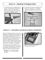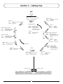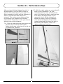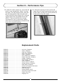
1
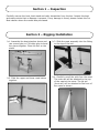
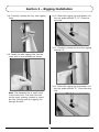
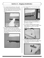
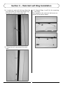
EP RTR Sailboat Owners Manual Specifications Length (Hull): 24 in (610mm) Height (Mast): 36.5 in (927mm) Beam: 6.25 in (158.75mm) Radio: Pro Boat 2-channel 27MHz AM Motor: 380-size The Pro Boat® Endeavor™ comes with the fiberglass hull built and painted and the RC equipment installed. All that’s left is rigging the sails. The two-piece mast makes disassembly and transport quick and easy. There is no better way to start enjoying the fun and excitement of RC sailing than with the Endeavor. The Endeavor features an electric back-up motor that ensures that you won't have any problems returning to shore in case of wind loss. The Endeavor also features a standard sail servo with no complicated pull-pull winch servo cables and comes readyto-run with battery, charger and transmitter. Just connect the pre-numbered sail rigging and start sailing. Head to the lake and begin sailing today with the perfect choice for any RC enthusiast. Sail area: Overall: 264 sq in (17.03 sq dm) Main: 170 sq in (10.97 sq dm) Jib (Front): 94 sq in (6.06 sq dm) ® Introduction Thank you for purchasing the Pro Boat® Endeavor™ EP ready-to-run sailboat. This craft has been designed to provide many hours of scale sailing pleasure, without the long hours of assembly usually associated with a model RC sailboat. The Endeavor EP can leisurely be completed in less than an hour. No Building! The Endeavor EP comes almost completely assembled. Its durable molded fiberglass hull has been prepainted for your convenience. You will only need to finish rigging the sails. The detailed instructions, photos and glossary at the back of the manual will allow you to easily complete the assembly. Table of Contents Introduction. . . . . . . . . . . . . . . . . . . . . . . . . . . . . . . . . . . . . . . . . . . . . . . . . . . . . . . 2 No Building!. . . . . . . . . . . . . . . . . . . . . . . . . . . . . . . . . . . . . . . . . . . . . . . . . . . . . . . 2 Table of Contents . . . . . . . . . . . . . . . . . . . . . . . . . . . . . . . . . . . . . . . . . . . . . . . . . . . 2 Items Required to Complete your Endeavor. . . . . . . . . . . . . . . . . . . . . . . . . . . . . . . . . 2 Section 1 – Inspection. . . . . . . . . . . . . . . . . . . . . . . . . . . . . . . . . . . . . . . . . . . . . . . . 3 Section 2 – Rigging Installation . . . . . . . . . . . . . . . . . . . . . . . . . . . . . . . . . . . . . . . . . 3 Section 2 – Rigging Installation . . . . . . . . . . . . . . . . . . . . . . . . . . . . . . . . . . . . . . . . . 4 Section 2 – Rigging Installation . . . . . . . . . . . . . . . . . . . . . . . . . . . . . . . . . . . . . . . . . 5 Section 2 – Rigging Installation . . . . . . . . . . . . . . . . . . . . . . . . . . . . . . . . . . . . . . . . . 6 Section 3 – Main Sail Luft Ring Installation . . . . . . . . . . . . . . . . . . . . . . . . . . . . . . . . . 7 Section 4 – Adjusting the Rigging Cables. . . . . . . . . . . . . . . . . . . . . . . . . . . . . . . . . . . 8 Section 5 – Transmitter and Receiver Battery Installation . . . . . . . . . . . . . . . . . . . . . . . 8 Section 6 – Checking the Radio System. . . . . . . . . . . . . . . . . . . . . . . . . . . . . . . . . . . . 9 Section 7 – Sailing Tips. . . . . . . . . . . . . . . . . . . . . . . . . . . . . . . . . . . . . . . . . . . . . . 10 Section 7 – Sailing Tips. . . . . . . . . . . . . . . . . . . . . . . . . . . . . . . . . . . . . . . . . . . . . . 11 Section 8 – Performance Tips. . . . . . . . . . . . . . . . . . . . . . . . . . . . . . . . . . . . . . . . . . 12 Section 8 – Performance Tips. . . . . . . . . . . . . . . . . . . . . . . . . . . . . . . . . . . . . . . . . . 13 Replacement Parts . . . . . . . . . . . . . . . . . . . . . . . . . . . . . . . . . . . . . . . . . . . . . . . . . 13 Plastic Parts. . . . . . . . . . . . . . . . . . . . . . . . . . . . . . . . . . . . . . . . . . . . . . . . . . . . . . 14 Basic Glossary . . . . . . . . . . . . . . . . . . . . . . . . . . . . . . . . . . . . . . . . . . . . . . . . . . . . 15 Diagram of Sailboat Rigging. . . . . . . . . . . . . . . . . . . . . . . . . . . . . . . . . . . . . . . . . . . 16 Warranty Information . . . . . . . . . . . . . . . . . . . . . . . . . . . . . . . . . . . . . . . . . . . . . . . 17 Items Required to Complete your Endeavor Phillips screwdriver Small pliers AA batteries (8) Threadlock 2 Section 1 – Inspection Carefully remove the boat, boat stand and radio transmitter from the box. Inspect the boat and make certain that no damage is present. If any damage is found, please contact the Pro Boat retailer where the model was purchased. Section 2 – Rigging Installation 1. Assemble the boat stand as shown and use a wood glue or CA hobby glue to bond the pieces together. Place the hull on the stand. 3. Slide the mast assembly into the fitting on the top of the hull. 2. Slide the upper and lower mast halves together. 4. Carefully unroll the sails from the mast. The main sail will be attached to the top of the mast at the crane. The jib sail (front sail) will be attached to the front of the crane as shown. 3 Section 2 – Rigging Installation 5. Locate the main sail boom. Slide the screw through the eyelet and use a Phillips screwdriver to secure the end of the boom. Do not over tighten as the sail boom will move as the sails are adjusted. Apply a drop of threadlock on the nut and thread it onto the screw from the bottom of the boom mount. 6. Locate the end of the main sail marked "G". Pass the line tied to the main sail through the hole in the rear end of the main sail boom. Pull the line until the main sail is taut, and the distance between the boom and sail is between 3/4-inch and 11/4-inch. Secure the excess line by wrapping it around the cleat and placing the end of the line in the notches of the cleat. 7. Locate the other end of the main sail. Pass the line tied to the main sail through the hole in the boom mount. Position the line so the distance between the boom and sail is equal to the other side of the sail. Secure the excess line by wrapping it around the cleat and placing the end of the line in the notches of the cleat. Note: Do not adjust the tension of any of the lines at this time. This will be done in Section 4, “Adjusting the Rigging Cables.” 4 Section 2 – Rigging Installation 8. Carefully unwrap the top, side rigging lines. 10. Open the rigging clip and attach it to the eye plate marked "C, D." Close the wire clip. 11. Carefully unwrap the mid-line rigging marked "D." 9. Insert the side rigging line into the outer hole in the spreader as shown. 12. Open the rigging clip and attach it to the eye plate marked "D." Close the wire clip. Note: The spreader has a small notch in the outer hole. The inner hole will not be used, making it easier to insert the line. Simply push the rigging line through the slot. 5 Section 2 – Rigging Installation 13. Locate the jib sail boom. The end of the jib boom with the cleat should be on the top and nearest the front of the boat. Pass the rigging line from the front of the jib sail into the hole on the end of the boom. 15. Repeat Step 17 for the other end of the jib sail. Hint: The jib boom will be parallel to the bottom of the jib sail once Steps 17 and 18 are complete. 16. Carefully unwrap the bow rigging cable marked "A." Attach the rigging cable to the fitting at the bow of the boat marked "A." 14. Position the line so the distance between the boom and sail is between 3/4-inch and 11/4-inch. Secure the excess line by wrapping it around the cleat and placing the end of the line in the notches of the cleat. 17. Carefully unwrap the stern rigging cable marked "B." Attach the rigging cable to the fitting at the stern of the boat marked "B." 6 Section 3 – Main Sail Luft Ring Installation 1. Locate one main sail luft ring. Open the ring and insert the small loop of the ring through the eyelet in the main sail. 3. Repeat Steps 1 and 2 for the remaining luft rings. The rigging for the main and jib booms are shown in the photos below. 2. Snap the luft ring around the main mast. 7 Section 4 – Adjusting the Rigging Cables 1. Locate the jib stay on rigging lines "C" and "D" on either side of the boat. Pull up carefully on the jib stay to adjust the tension so there is no slack in the line. Work slowly and adjust both lines so the main mast is completely vertical. 2. Adjust the jib stay on the rigging line at the bow "A" and stern "B" of the boat. Tension the rigging lines so the mast is perpendicular (square) to the hull of the boat. Section 5 – Transmitter and Receiver Battery Installation Install 8 AA alkaline batteries into the radio transmitter, following the instructions for your radio system. Carefully place the sailboat hull into the included boat stand, if it is not already there. Next, remove the radio box lid (scale cockpit) of the boat carefully, as it is secured by magnets at the rear of the cockpit. Locate and charge the power battery pack for 2-3 hours, closely monitoring the temperature of the pack. If it becomes warm to the touch, immediately end charging. Confirm that the receiver switch is in the "off" position and that the sail servo arm is not touching the power switch. Connect the power battery. Secure the battery to the battery box with hook and loop material. Note: The radio box lid has been removed for photography. Warning: Do not charge the battery overnight or on or near flammable materials. 8 Section 6 – Checking the Radio System Turn on the radio system and test it to make certain it is functioning correctly. First, turn on the transmitter. Next, turn on the switch that controls the receiver. • Moving the right stick of your transmitter will control the rudder. To turn to the right, simply move the stick to the right, and the rudder should also move to the right. Do the opposite to turn left. • Moving the left stick of the transmitter will control the sails. By moving the left stick upward, you will let the sails out. By pulling the left stick down, you will tighten the sails. • Always extend the transmitter antenna prior to sailing. • When the radio system is working correctly and the sails and fittings are properly adjusted, you are ready to sail. • Once the sails are pulled in, with the sail control in the fully lower position, move the sail trim adjustment toward the bottom of the transmitter to operate the motor. • After sailing, turn the receiver off before turning the transmitter off. Never sail with the sail trim adjusted to a position that will allow the motor to turn on. Note: The motor is for intermittent use only. If you notice the power slowing, stop motor use immediately and recharge the battery. Continued use will cause the radio system to lose control. 9 Section 7 – Sailing Tips The following will help you get started in sailing. Follow the instructions and understand it takes some practice to become an accomplished yachtsman. Do not sail if the winds are too strong. Best results will occur with winds between 5 and 12 mph. WIND Port Tack Starboard Tack Close-Hauled NO SAIL ZONE 45° Close-Hauled 45° Wind Abeam Wind Abeam Starboard Tack Port Tack Quarter Lee Running 10 Quarter Lee Section 7 – Sailing Tips WIND Wind Abeam Sails: Each at a position of 45° Rudder: In center position Quarter Lee Sails: Letting both out a little more Rudder: To the left Bearing Away Sails: Let both out so as not to shiver Rudder: To the left STARBOARD TACK Tacking Sails: Keeping pulled in Rudder: To the left Port Tack—Close-Hauled Sails: Keeping pulled in Rudder: To be held at the center as long as the sails do not shiver Starboard Tack—Running Sails: Letting both out to their maximum position Rudder: In center position Tacking Sails: Keeping pulled in Rudder: To the left Starboard Tack—Close-Hauled Sails: Keeping pulled in Rudder: To be held at the center as long as the sails do not shiver Port Tack—Running Sails:Letting both out to their maximum position Rudder: In center position 45° Tacking Sails: Keeping pulled in Rudder: To the right Quarter Lee Sails: Pulling both in a little Rudder: In center position PORT TACK Port Tack—Close-Hauled Sails: Keeping pulled in Rudder: To be held at the center as long as the sails do not shiver START Luffing Up Sails: Pulling in bit by bit Rudder: To the left Wind Abeam Sails: Each at a position of 45° Rudder: In center position Luffing Up Sails: Pulling both in all the way Rudder: To the left Rudder Control Sails Control 11 Section 8 – Performance Tips After you have finished rigging the sails, it will be helpful to trim the sails in order to optimize the performance of your boat. It is often necessary to briefly sail the Endeavor in order to see how the sails need to be trimmed. This section covers hints and tips for trimming your Endeavor for the best performance. Remember to take your time to optimize your sailing pleasure. 2. With the radio system on, move the left stick on your transmitter "up" and manually push the main sail and jib sail open. You should be able to open the sails to at least a 60-degree angle. If you cannot do this, it will be necessary to adjust the length of the line (allowing more slack) by adjusting the jib stays located underneath the main sail and jib sail booms. See Section 3 Step 3 for rigging adjustment locations 1. Check to make sure the main boom and jib boom are in line with each other. Adjust the jib stay at the top of the jib sail to position the jib boom. 12 Section 8 – Performance Tips 3. With the radio system on, move the left stick of your transmitter "down" to close the sails. The sails should close, with the jib sail being tighter than the main sail. There should be some slack left in the sail rigging when the sail gimbal moves the sails in. There should also be enough movement to turn on the motor switch when the trim adjustment is moved to the lower fully trimmed position. 4. Bend the opening of each of the luft rings after you have secured the main sail to the mast, so they will not be pulled out of the sail or from the mast. Replacement Parts PRB2451 . . . . . . . . . . . . . . . . . . . PRB2452 . . . . . . . . . . . . . . . . . . . PRB2453 . . . . . . . . . . . . . . . . . . . PRB2454 . . . . . . . . . . . . . . . . . . . PRB3010 . . . . . . . . . . . . . . . . . . . PRB2456 . . . . . . . . . . . . . . . . . . . PRB2457 . . . . . . . . . . . . . . . . . . . PRB2458 . . . . . . . . . . . . . . . . . . . PRB2459 . . . . . . . . . . . . . . . . . . . PRB2460 . . . . . . . . . . . . . . . . . . . PRB2461 . . . . . . . . . . . . . . . . . . . PRB2462 . . . . . . . . . . . . . . . . . . . PRB2463 . . . . . . . . . . . . . . . . . . . PRB2181 . . . . . . . . . . . . . . . . . . . PRB2183 . . . . . . . . . . . . . . . . . . . PRB2186 . . . . . . . . . . . . . . . . . . . PRB2187 . . . . . . . . . . . . . . . . . . . PRB2188 . . . . . . . . . . . . . . . . . . . PRB2407 . . . . . . . . . . . . . . . . . . . PRB2409 . . . . . . . . . . . . . . . . . . . Hull only: Endeavor Hatch: Endeavor Mast Set: Endeavor Boom Set: Endeavor Motor: Endeavor Drive Shaft Set: Endeavor Plastic Parts Set: Endeavor Rudder: Endeavor Pushrod Set: Endeavor Sails: Endeavor Power Switch: Endeavor Wiring Harness: Endeavor Boat Stand: Endeavor Screw Lock Pushrod Connector Rigging Line Clips Sail Luft Rings Pushrod Nylon Clevis Sail Boom Screw and Eyelet Plastic Parts Tree Rigging Line 13 Plastic Parts Spreader Masthead Crane Cleat Rigging Line Grommet Eye Plate Boom Plug Mast Holder Gooseneck Boom Pivot Mast Joiner Jib Stay 14 Basic Glossary Beam Reach Sailing at approximately 90 degrees to the wind source with the wind coming from abeam. Port The left side of the boat (when facing forward). Rudder Vertical plate attached at the stern, controlling the movements of the boat. Beating Sailing toward the wind source or against the wind with the sails pulled in all the way, tacking as you go, to reach a destination upwind. Starboard The right side of the boat (when facing forward). Boom The horizontal spar to which the foot of a sail is attached. Starboard Tack and Port Tack The right side of the boat is called the starboard side and the left side is called port. When the boat sails with the wind coming across the starboard side and the main sail is on the port side, the boat is sailing on a starboard tack. When the boat sails with the wind coming across the port side of the boat and the main sail on the starboard side, the boat is sailing on a port tack. Bow The forward end of a boat. Cleat A fitting to which the rigging line may be secured. Downwind Sailing away from the wind with the sails let out all the way. Stern The back end of a boat. Jib Sail The smaller sail attached at the bow of the boat. Tack To turn the bow of a sailboat through the wind so the sails fill to the opposite side. Jib Stay Device used to adjust the tension of the rigging lines. Weather Helm The natural tendency of a boat to turn toward the wind. Knot One nautical mile per hour (one knot equals 1.2 mph). Main Sail The largest working sail that is attached to the mast. Mast Vertical spar to which the rigging and sails are attached. 15 Diagram of Sailboat Rigging 49.25 in [1250mm] 42.5 in [1080mm] 65.35 in [1660mm] 42.5 in [1080mm] 19.68 in [500mm] 9.84 in [250mm] 22.83 in [580mm] 11 in [280mm] 16 Warranty Information Age Recommendation Damage Limits Age Recommendation: 14 years or over. This is not a toy. This product is not intended for use by children without direct adult supervision. HORIZON SHALL NOT BE LIABLE FOR SPECIAL, INDIRECT OR CONSEQUENTIAL DAMAGES, LOSS OF PROFITS OR PRODUCTION OR COMMERCIAL LOSS IN ANY WAY CONNECTED WITH THE PRODUCT, WHETHER SUCH CLAIM IS BASED IN CONTRACT, WARRANTY, NEGLIGENCE, OR STRICT LIABILITY. Further, in no event shall the liability of Horizon exceed the individual price of the Product on which liability is asserted. As Horizon has no control over use, setup, final assembly, modification or misuse, no liability shall be assumed nor accepted for any resulting damage or injury. By the act of use, setup or assembly, the user accepts all resulting liability. If you as the Purchaser or user are not prepared to accept the liability associated with the use of this Product, you are advised to return this Product immediately in new and unused condition to the place of purchase. Law: These Terms are governed by Illinois law (without regard to conflict of law principals). Warranty Period Exclusive Warranty- Horizon Hobby, Inc., (Horizon) warranties that the Products purchased (the “Product”) will be free from defects in materials and workmanship at the date of purchase by the Purchaser. Limited Warranty (a) This warranty is limited to the original Purchaser (“Purchaser”) and is not transferable. REPAIR OR REPLACEMENT AS PROVIDED UNDER THIS WARRANTY IS THE EXCLUSIVE REMEDY OF THE PURCHASER. This warranty covers only those Products purchased from an authorized Horizon dealer. Third party transactions are not covered by this warranty. Proof of purchase is required for warranty claims. Further, Horizon reserves the right to change or modify this warranty without notice and disclaims all other warranties, express or implied. (b) Limitations- HORIZON MAKES NO WARRANTY OR REPRESENTATION, EXPRESS OR IMPLIED, ABOUT NON-INFRINGEMENT, MERCHANTABILITY OR FITNESS FOR A PARTICULAR PURPOSE OF THE PRODUCT. THE PURCHASER ACKNOWLEDGES THAT THEY ALONE HAVE DETERMINED THAT THE PRODUCT WILL SUITABLY MEET THE REQUIREMENTS OF THE PURCHASER’S INTENDED USE. (c) Purchaser Remedy- Horizon’s sole obligation hereunder shall be that Horizon will, at its option, (i) repair or (ii) replace, any Product determined by Horizon to be defective. In the event of a defect, these are the Purchaser’s exclusive remedies. Horizon reserves the right to inspect any and all equipment involved in a warranty claim. Repair or replacement decisions are at the sole discretion of Horizon. This warranty does not cover cosmetic damage or damage due to acts of God, accident, misuse, abuse, negligence, commercial use, or modification of or to any part of the Product. This warranty does not cover damage due to improper installation, operation, maintenance, or attempted repair by anyone other than Horizon. Return of any goods by Purchaser must be approved in writing by Horizon before shipment. Safety Precautions This is a sophisticated hobby Product and not a toy. It must be operated with caution and common sense and requires some basic mechanical ability. Failure to operate this Product in a safe and responsible manner could result in injury or damage to the Product or other property. This Product is not intended for use by children without direct adult supervision. The Product manual contains instructions for safety, operation and maintenance. It is essential to read and follow all the instructions and warnings in the manual, prior to assembly, setup or use, in order to operate correctly and avoid damage or injury. Questions, Assistance, and Repairs Your local hobby store and/or place of purchase cannot provide warranty support or repair. Once assembly, setup or use of the Product has been started, you must contact Horizon directly. This will enable Horizon to better answer your questions and service you in the event that you may need any assistance. For questions or assistance, please direct your email to [email protected], or call 888.899.LOSI (5674) toll free to speak to a service technician. 17 Warranty Information Inspection or Repairs United States: Electronics and engines requiring inspection or repair should be shipped to the following address: If this Product needs to be inspected or repaired, please call for a Return Merchandise Authorization (RMA). Pack the Product securely using a shipping carton. Please note that original boxes may be included, but are not designed to withstand the rigors of shipping without additional protection. Ship via a carrier that provides tracking and insurance for lost or damaged parcels, as Horizon is not responsible for merchandise until it arrives and is accepted at our facility. A Service Repair Request is available at www. horizonhobby.com on the “Support” tab. If you do not have internet access, please include a letter with your complete name, street address, email address and phone number where you can be reached during business days, your RMA number, a list of the included items, method of payment for any non-warranty expenses and a brief summary of the problem. Your original sales receipt must also be included for warranty consideration. Be sure your name, address, and RMA number are clearly written on the outside of the shipping carton. Horizon Service Center 4105 Fieldstone Road Champaign, Illinois 61822 All other Products requiring warranty inspection or repair should be shipped to the following address: Horizon Product Support 4105 Fieldstone Road Champaign, Illinois 61822 Please call 877-504-0233 or e-mail us at [email protected] with any questions or concerns regarding this product or warranty. United Kingdom: Electronics and engines requiring inspection or repair should be shipped to the following address: Horizon Hobby UK Units 1-4 Ployters Rd Staple Tye Harlow, Essex CM18 7NS United Kingdom Warranty Inspection and Repairs To receive warranty service, you must include your original sales receipt verifying the proof-ofpurchase date. Provided warranty conditions have been met, your Product will be repaired or replaced free of charge. Repair or replacement decisions are at the sole discretion of Horizon Hobby. Please call +44 (0) 1279 641 097 or e-mail us at [email protected] with any questions or concerns regarding this product or warranty. Non-Warranty Repairs Should your repair not be covered by warranty the repair will be completed and payment will be required without notification or estimate of the expense unless the expense exceeds 50% of the retail purchase cost. By submitting the item for repair you are agreeing to payment of the repair without notification. Repair estimates are available upon request. You must include this request with your repair. Non-warranty repair estimates will be billed a minimum of ½ hour of labor. In addition you will be billed for return freight. Please advise us of your preferred method of payment. Horizon accepts money orders and cashiers checks, as well as Visa, MasterCard, American Express, and Discover cards. If you choose to pay by credit card, please include your credit card number and expiration date. Any repair left unpaid or unclaimed after 90 days will be considered abandoned and will be disposed of accordingly. Please note: non-warranty repair is only available on electronics and model engines. Germany: Electronics and engines requiring inspection or repair should be shipped to the following address: Horizon Technischer Service Hamburger Strasse 10 25335 Elmshorn Germany Please call +49 4121 46199 66 or e-mail us at [email protected] with any questions or concerns regarding this product or warranty. 18 Warranty Information FCC Information Declaration of Conformity This device complies with part 15 of the FCC rules. Operation is subject to the following two conditions: (1) This device may not cause harmful interference, and (2) This device must accept any interference received, including interference that may cause undesired operation. Caution: Changes or modifications not expressly approved by the party responsible for compliance could void the user’s authority to operate the equipment. (in accordance with ISO/IEC 17050-1) No. HH20090323 Product(s): Item Number(s): Endeavor Sailboat EP RTR PRB2450 Equipment class: 1 The object of declaration described above is in conformity with the requirements of the specifications listed below, following the provisions of the European R&TTE directive 1999/5/EC: CE Compliance Information for the European Union Instructions for Disposal of WEEE by Users in the European Union This product must not be disposed of with other waste. Instead, it is the user’s responsibility to dispose of their waste equipment by handing it over to a designated collection point for the recycling of waste electrical and electronic equipment. The separate collection and recycling of your waste equipment at the time of disposal will help to conserve natural resources and ensure that it is recycled in a manner that protects human health and the environment. For more information about where you can drop off your waste equipment for recycling, please contact your local city office, your household waste disposal service or where you purchased the product. EN 300-220Technical requirements for Radio equipment. EN 301 489-1, 301 489-3 General EMC requirements for Radio equipment EN 60950 Safety Signed for and on behalf of: Horizon Hobby, Inc. Champaign, IL USA March 23, 2009 Steven A. Hall Vice President International Operations and Risk Management Horizon Hobby, Inc. 19 ® © 2009, Horizon Hobby, Inc. 4105 Fieldstone Road Champaign, Illinois 61822 (877) 504-0233 www.horizonhobby.com Printed 03/2009 15242