1
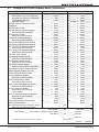
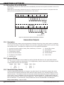
INSTALLATION GUIDE
XRSUPER6 / XR20 / XR40
COMMAND PROCESSOR™ PANELS
MODEL XRSuper6/XR20/XR40
COMMAND PROCESSOR
INSTALLATION GUIDE
FCC NOTICE
This equipment generates and uses radio frequency energy and, if not installed and used properly in
strict accordance with the manufacturer’s instructions, may cause interference with radio and television
reception. It has been type tested and found to comply with the limits for a Class B computing device
in accordance with the specification in Subpart J of Part 15 of FCC Rules, which are designed to provide
reasonable protection against such interference in a residential installation. If this equipment does cause
interference to radio or television reception, which can be determined by turning the equipment off and on,
the installer is encouraged to try to correct the interference by one or more of the following measures:
Reorient the receiving antenna
Relocate the computer with respect to the receiver
Move the computer away from the receiver
Plug the compute into a different outlet so that computer and receiver are on different branch circuits
If necessary, the installer should consult the dealer or an experienced radio/television technician
for additional suggestions. The installer may find the following booklet, prepared by the Federal
Communications Commission, helpful:
“How to identify and Resolve Radio-TV Interference Problems.”
This booklet is available from the U.S. Government Printing Office, Washington D.C. 20402
Stock No. 004-000-00345-4
© 1995 - 2006 Digital Monitoring Products, Inc.
Information furnished by DMP is believed to be accurate and reliable.
This information is subject to change without notice.
TABLE OF CONTENTS
Revisions to This Document
Panel Specifications
1.1
1.2
1.3
1.4
1.5
1.6
Power Supply .........................................1
Communication.......................................1
Panel Zones............................................1
Keypads .................................................1
Outputs..................................................1
Enclosure Specifications ..........................1
Introduction
2.1
2.2
2.3
2.4
2.5
Description .............................................2
System Configurations.............................2
Before You Begin ....................................2
About this Guide .....................................2
How to Use this Guide.............................2
System Components
3.1
3.2
3.3
3.4
3.5
Description .............................................3
Wiring Diagram.......................................3
Lightning Protection ................................3
Command Processor Accessories..............3
XRSuper6/XR20/XR40 Wiring Diagram......4
Installation
4.1
4.2
4.3
Mounting the Enclosure...........................5
Mounting Keypads ..................................6
Installation Specifications ........................6
Primary Power Supply
5.1
5.2
AC terminals 1 and 2...............................6
Transformer Types ..................................6
Secondary Power Supply
6.1
6.2
6.3
6.4
6.5
6.6
6.7
Battery Terminals 3 and 4........................7
Earth Ground..........................................7
Replacement Period ................................7
Discharge/Recharge ................................7
Battery Supervision .................................7
XRSuper6/XR20/XR40 Power
Requirements .........................................7
XRSuper6/XR20/XR40 Standby
Battery Calculations ................................8
Bell Output
7.1
Terminals 5 and 6 ...................................9
Keypad Data Bus
8.1
8.2
8.3
8.4
8.5
8.6
8.7
Description .............................................9
Terminal 7 - RED ....................................9
Terminal 8 - YELLOW ..............................9
Terminal 9 - GREEN ................................9
Terminal 10 - BLACK ...............................9
Programming Connection ........................9
Keypad Addressing..................................9
Smoke and Glassbreak Detector Output
9.1
XRSuper6/XR20/XR40 Installation Guide
Terminal 11 ............................................9
Digital Monitoring Products
i
TABLE OF CONTENTS
Burglary Zones
10.1
10.2
10.3
10.4
Description ...........................................10
Operational Parameters .........................10
Zone Response Time .............................10
Keyswitch Arming Zone .........................10
Powered Zone for 2-Wire Smoke Detectors
11.1
Terminals 25 and 26..............................11
11.2 Wiring Zone 10 on XR20/XR40 ...................12
Annunciator Outputs
12.1
12.2
12.3
Description ...........................................12
Harness Wiring .....................................12
Model 860 Relay Module........................12
Telephone RJ Connector
13.1
13.2
13.3
13.4
Description ...........................................13
FCC Registration ...................................13
Notification...........................................13
Ground Start ........................................13
Reset Jumpers J16
14.1
Description ...........................................13
Universal UL Burglary Specifications
15.1
15.2
15.3
15.4
15.5
15.6
15.7
15.8
Introduction .........................................14
Wiring..................................................14
Police Station Phone Numbers ...............14
Bypass Reports .....................................14
System Maintenance .............................14
Cross-Zoning ........................................14
Ground Start ........................................14
UL Listed Receivers ...............................14
UL 1023 Specifications
16.1
16.2
16.3
16.4
16.5
16.6
Bell Cutoff ............................................14
Entry Delay ..........................................14
Exit Delay.............................................14
Zone Expansion on 4-Wire Bus...............14
Wireless External Contact ......................15
Wireless Supervision Time .....................15
UL 1610 and 1076 Specifications
17.1
17.2
17.3
17.4
17.5
17.6
17.7
17.8
Digital Monitoring Products
ii
Opening/Closing Reports .......................15
Automatic Bell Test ...............................15
Proprietary Dialer..................................15
AA High Line Network Security...............15
Wireless Arming Mode...........................15
Wireless Tamper ...................................15
Wireless External Contact ......................15
Wireless Supervision Time .....................15
XRSuper6/XR20/XR40 Installation Guide
TABLE OF CONTENTS
UL 365 And 609 Specifications
18.1
18.2
18.3
18.4
18.5
18.6
18.7
18.8
18.9
18.10
18.11
18.12
Entry Delay ..........................................16
Grade A Bell .........................................16
Bell Cutoff ............................................16
Automatic Bell Test ...............................16
Grade A Mercantile................................16
Mercantile Safe and Vault ......................16
Line Security for Police Connect .............16
AA High Line Network Security...............16
Wireless Arming Mode...........................16
Wireless Tamper ...................................16
Wireless External Contact ......................16
Wireless Supervision Time .....................16
UL 1635 Specifications
19.1
19.2
19.3
19.4
19.5
19.6
Digital Dialer Telephone Number ............17
Entry Delay ..........................................17
Exit Delay.............................................17
Test Frequency .....................................17
Automatic Bell Test ...............................17
Grade B Central Station .........................17
Universal UL And NFPA Fire Alarm Specifications
20.1
20.2
20.3
20.4
20.5
20.6
20.7
20.8
Introduction .........................................17
Wiring..................................................17
Police station phone number..................17
System maintenance .............................17
Audible alarm .......................................17
Fire zone programming .........................17
Ground Start ........................................17
UL Listed Receivers ...............................17
UL 985 NFPA 72 (Chapter 2) Specifications
21.1
21.2
21.3
21.4
21.5
Bell output definition .............................18
Indicating Circuit Supervision.................18
Wireless External Contact ......................18
Wireless Supervision Time .....................18
Wireless Fire Verification........................18
California State Fire Marshal Specifications
22.1
Bell Output Definition ............................18
Troubleshooting
23.1
23.2
24.1
24.2
Troubleshooting Section ........................19
Common Keypad Displays......................19
Multiple Indicating Circuit Module
Installation ...........................................20
Installation for Derived Channel Burglary 21
OPERATING INSTRUCTIONS MODEL
XRSuper6/XR20/XR40 PANELS
Listings and Approvals
XRSuper6/XR20/XR40 Installation Guide
Digital Monitoring Products
iii
REVISIONS
Revisions to This Document
This section explains the changes that were made to this document during this revision. This section lists
the date the change was made, the section number and heading, and a quick summary of the change.
Date
8/06
Section Number and Heading
3.5 Wiring Diagram
6.1 Battery Terminals 3 & 4
Listings and Approvals
Summary of Changes
Added SIA CP-01 information.
Added figure and text to clarify use of battery harnesses
and PTC. Note: Subsequent figure numbers changed.
Removed obsolete products.
Added figure to clarify phone jack wiring operation.
Added figure to clarify and revised text.
Added False Alarm Reduction features to meet SIA CP-01.
Note: Subsequent section numbers changed.
Added SIA CP-01 certification.
5/06
17.5 Wireless Arming Mode
17.6 Wireless Tamper
17.7 Wireless External Contact
17.8 Wireless Supervision Time
18.9 Wireless Arming Mode
18.10 Wireless Tamper
18.11 Wireless External contact
18.12 Wireless Supervision Time
21.3 Wireless External Contact
21.4 Wireless External contact
21.5 Wireless Fire Verification
23.2 Common Keypad Displays
Added Wireless operation information.
Added Wireless operation information.
Added Wireless operation information.
Added Wireless operation information.
Added Wireless operation information.
Added Wireless operation information.
Added Wireless operation information.
Added Wireless operation information.
Added Wireless operation information.
Added Wireless operation information.
Added Wireless operation information.
Revised table to reflect valid messages and their operation.
2/06
16.5 Wireless External Contact
16.6 Wireless Supervision Time
Added Wireless operation information.
Added Wireless operation information.
6.7 Standby Battery Calculation
13.1 Telephone RJ Connector
14.1 Reset Jumper J16
23.1 through 23.9
12/05 3.5 Wiring Diagram
6.7 Standby Battery Calculation
Added Aqualite keypad models.
Added Aqualite keypad models.
9/05
3.5 Wiring Diagram
6.7 Standby Battery Calculation
Added 7760 keypad.
Added 7760 keypad.
7/05
3.5 Wiring Diagram
Added Power Limited terminal information.
6/05
3.5 Wiring Diagram
17.4 AA High Line Network Security
19.8 AA High Line Network Security
Listings and Approvals
Added
Added
Added
Added
12/04 Entire Document
1.6 Enclosure Specifications
3.5 Wiring Diagram
4.1 Mounting the Enclosure
4.3 Installation Specifications
6.7 Standby Battery Calculations
Back Cover
3/04
1.6 Enclosure Specifications
3.5 Wiring Diagram
Sections 3.4 and 6.7
4.1 Mounting the Enclosure
24.2 Installation for Derived
Channel Burglary
Digital Monitoring Products
iv
UL AA High
UL AA High
UL AA High
UL AA High
Line
Line
Line
Line
Security
Security
Security
Security
information.
information.
Information.
information.
Added 734 Module and Thinline keypads where applicable.
Added 341 and 342 Enclosure information. Removed 350
Enclosure information.
Updated keypad listing.
Added 341 and 342 Enclosure options. Removed 350
Enclosures option.
Updated wiring text.
Revised current draw values, added Thinline keypads, added
734 Module, corrected Total multiplier value.
Added Listings and Approvals
Added 350 Enclosure information
Added resistor part numbers and updated power supervision
relay information.
Added keypad models 690F, 790F, and 693.
Added/revised current draw information.
Added 350 Enclosure as an option.
Revised drawing and added STU connection text.
XRSuper6/XR20/XR40 Installation Guide
INTRODUCTION
Panel Specifications
1.1
Power Supply
Transformer Input:
Wire-in — 16.5 VAC 40 VA, Model 320
Plug-in — 16.5 VAC 40 VA, Model 321
Standby Battery:
12 VDC 7.0 Ah (40 VA transformer charges up to 2 batteries)
Auxiliary Output:
12 VDC at 500mA
Bell Output:
12 VDC at 1.5 Amps
Smoke Detector Output: 12 VDC at 100mA
All circuits inherent power limited
1.2
Communication
Built-in SDLC Digital Dialer communication to DMP Model SCS-1 and SCS-1R Receivers
Built-in 4-2 communication to non-DMP receivers
Built-in M2E (Radionics Modem IIe) communication to non-DMP receivers
Built-in CID (Contact ID) communication to non-DMP receivers
Any panel can operate as a local system.
1.3
Panel Zones
Nine 1k Ohm EOL burglary zones: zones 1 to 9 on XR20 and XR40 panels, and zones 1 to 5 on the XRSuper6.
One 3.3k Ohm EOL Class B powered fire zone with reset capability: zone 6 on the XRSuper6, and zone 10 on
XR20 and XR40 panels.
1.4
Keypads
You can connect up to four supervised keypads to the XRSuper6/XR20 panels and eight supervised keypads on
the XR40.
• 16 or 32-character alphanumeric keypads
• 10-zone LED keypads
In addition, the following zone expanders can be added to the XRSuper6/XR20/XR40 panels:
• One, four, eight and 16-zone expansion modules
• Single-zone PIR and glassbreak detectors
• One 738A Ademco Wireless interface for up to 32 points of zone expansion
• One FA426 Wireless receiver for up to 16 points of zone expansion (Two FA426 on the XR40)
When using the FA426 Wireless Receiver, you can add unsupervised devices to address five of the XRSuper6
and XR20.
1.5
Outputs
The XRSuper6/XR20/XR40 panels provide four open collector outputs rated for 50mA each. A Model 300
Output Harness is required. The open collector outputs provide the ground connection for a positive voltage
source.
1.6
Enclosure Specifications
The XRSuper6/XR20/XR40 panel ships in an enclosure with EOL resistors, battery leads, user’s guide, and
programming sheet. All enclosures are constructed using 20-gauge cold rolled steel except where noted.
Model 340 Enclosure
Enclosure size:
Color:
12.5” W x 9.5” H x 2.75” D
Gray (G)
Model 349 Enclosure
Enclosure size:
Color:
12.5” W x 11.25” H x 3.5” D
Gray (G) or Red (R)
Model 341 Enclosure
Enclosure size:
Color:
12.75” W x 6.55” H x 2.9” D
Gray (G)
Model 342 Enclosure
Enclosure size:
Color:
11” W x 5” H x 2.75” D
Gray (G)
Model 350A Enclosure
Enclosure size:
17.1” W x 13.2” H x 3.7” D
Color:
Gray (G)
Construction:
18-gauge with 16-gauge door
XRSuper6/XR20/XR40 Installation Guide
Digital Monitoring Products
1
INTRODUCTION
Introduction
2.1
Description
The DMP XRSuper6/XR20/XR40 Command Processor™ panels are powerful 12 VDC burglary and fire
communicator panels with battery backup. The XR20 and XR40 panels provide nine on-board burglary zones
and one on-board 12 VDC Class B powered fire zone. The XRSuper6 provides five burglary zones and one fire
zone. The fire zone has a reset capability to provide for 2-wire smoke detectors, relays, or other latching
devices. The panels can communicate to one or two DMP SCS-1/SCS-1R Receivers using SDLC digital dialer,
4-2, or Contact ID (CID) reporting formats. In addition, the XRSuper6/XR20/XR40 can communicate using the
Radionics Modem IIe format.
2.2
System Configurations
The panels can be programmed to operate as either an All/Perimeter system that provides one Perimeter
area and one Interior area, or as a Home/Sleep/Away system that provides one Perimeter, one Interior, and
one Bedroom area. The Bedroom area can include any protection devices the user wants disarmed during
their sleeping hours and armed in the Away mode. In addition, the XR20/XR40 can operate as a four area
system.
2.3
Before You Begin
Before installing the panel, we recommend you read through the entire contents of this guide. Familiarize
yourself with the features of the panel and the key points to remember during the installation. Be sure to
read and understand all of the caution statements printed in bold italics. In addition to this installation
guide, you should also read through and familiarize yourself with these other product documents:
•
•
•
•
2.4
XRSuper6/XR20/XR40 Programming Guide (LT-0305) • XR20 Security Command User’s Guide (LT-0303)
XRSuper6 Programming Sheet (LT-0621)
• XR40 Programming Sheet (LT-0493)
XRSuper6 Security Command User’s Guide (LT-0622) • XR40 Security Command User’s Guide (LT-0494)
XR20 Program Information Sheet (LT-0302)
About this Guide
The information contained in this guide is organized into five sections:
• The Table of Contents at the front of this guide lists all of the headings and the page number where
the information can be found.
• The Introduction section gives you an overview of the various components that go into a
panel system and diagrams some typical system configurations.
• The Installation section begins with mounting instructions for the enclosure and takes you through the
proper way to power up the panel prior to programming.
• The Compliance section lists various standards to which the panels comply.
• The Wiring Diagram section provides common system drawings for the panels.
Caution notes
Throughout this guide you will see caution notes containing information you need to know when installing
the panel. These cautions are indicated with a yield sign. Whenever you see a caution note, make sure you
completely read and understand its information. Failing to follow the caution note can cause damage to the
equipment or improper operation of one or more components in the system. See the example shown below.
Always ground the panel before applying power to any devices: The panel must be properly grounded
before connecting any devices or applying power to the panel. Proper grounding protects against
Electrostatic Discharge (ESD) that can damage system components.
2.5
How to Use this Guide
To locate information about the installation of the panel, first go to the Table of Contents at the front of
this guide. Find the subject heading that closely describes the information you need and turn to the section
number shown to the right of the heading.
The text that follows the heading has been written to provide as much information about the subject as
possible. If you cannot find the information you need under that heading, try scanning through a few of the
headings before and after and reading the text under those that sound similar.
Digital Monitoring Products
2
XRSuper6/XR20/XR40 Installation Guide
INTRODUCTION
System Components
3.1
Description
The DMP system is made up of an alarm panel with built in communicator, an enclosure, a 16.5 VAC
transformer, and a 12 VDC 7.0 Ah battery. You can add Security Command keypads to the system and can
also connect auxiliary devices to the panel’s open collector outputs to expand the basic system. Combined
current requirements of additional modules may require an auxiliary power supply. Refer to the Standby
Battery Power Calculation section in this guide when calculating power requirements. In addition, up to 32
points of zone expansion can be added to the XR40, and 16 points to the XR20 and XRSuper6.
3.2
Wiring Diagram
The system wiring diagram in Figure 1, on the following page, shows some of the accessory devices you can
connect for use in various applications. A complete description of each module follows.
3.3
Lightning Protection
Metal Oxide Varistors and Transient Voltage Suppressors help protect against voltage surges on input and
output circuits. A transorb is provided for the Smoke Detector Output Circuit (Terminal 11). This transient
protection provides additional resistance to electrical surges such as lighting. Additional surge protection is
available by installing the DMP 370 or 370RJ Lightning Suppressors.
3.4
Command Processor Accessories
You can connect any combination (up to four on XRSuper6 and XR20, and up to eight on XR40) of vacuum
fluorescent, LCD, or LED keypads to the 4-wire keypad data bus provided by the panel on terminals 7, 8, 9,
and 10. Also, you can connect Model 712-8 714, 715, 714-8, 714-16, 715-8, 715-16 Zone Expansion Modules
to the keypad bus. Additionally, you can connect one Model 738A Ademco Interface Module or one Model
FA426 Wireless Receiver to the keypad bus. You can connect one additional Model FA426 Wireless Receiver
to the XR40 keypad bus.
XRSuper6/XR20/XR40 Installation Guide
Digital Monitoring Products
3
INTRODUCTION
3.5 XRSuper6/XR20/XR40 Wiring Diagram
RJ Cable Monitor J7
Use DMP Model 306 Harness
J7
RJ SUP
Phone Jack Connector
J8
RED
PROG
4
6
8
7
10
9
Bell
22 gauge minimum
Cold Water Pipe Earth Ground
22 gauge minimum
s
22 gauge minimum
s
Maximum AC Wire distance
with 16 gauge wire: 70 feet
with 18 gauge wire: 40 feet
RED
BLACK
Up to 500mA auxiliary
current at 10.4 to 13.2
VDC from Terminals
7, 11, 25, and 26.
5
11 12
14
13
s
s
s
s
s
Z5 GND Z6
15
18
Zone 2
Z3 GND Z4
s
s
16
17
Zone 3
3
Zone 1
2
BLACK
Keypads
Models 690/690F/790/790F
77mA at 12 VDC Nominal
Model 692
70mA at 12 VDC Nominal
Model 693/793
92mA at 12 VDC Nominal
Model 7060
80mA at 12 VDC Nominal
Model 7070
72mA at 12 VDC Nominal
Model 7063
86mA at 12 VDC Nominal
Model 7073
93mA at 12 VDC Nominal
Model 7760
65mA at 12 VDC Nominal
1
s
s
s
s
20
19
s
s
s
s
s
1k
Ohm
RED
1k
Ohm
1k
Ohm
1k
Ohm
1k
Ohm
1k
Ohm
22
21
s
Z9 Z10+ Z10-
23
s
s
25
24
26
XRSuper6 Zone 6
compatibility
identifier: A
XR20 and XR40
Zone 10
compatibility
identifier: A
s
1k
Ohm
1k Ohm
s = Supervised Circuit
Maximum operating
range:
8.8 VDC - 14.2 VDC.
1k Ohm
BLACK
Use UL Listed Power
Supervision Relay
rated at 12 VDC.
Smoke
Detector
Smoke Output
100mA @10.4 - 13.2 VDC Terminal 11
Minimum voltage on Auxiliary output to
process Sensor trips is 10.2 VDC.
UL Listed Resistors
1.0k Ohm - DMP Model 311
3.3k Ohm - DMP Model 309
10K Ohm - DMP Model 308
See the list of approved 2-wire
smoke detectors in Section 11.1 in
the Installation Guide (LT-0624).
10.4 - 13.2 VDC Total current:
1.5 Amps max. w/ 40 VA — 600mA w/ 20 VA
Z7 GND Z8
s
3.3k Ohm
Bell
Heat detectors,
manual pull stations,
or any other shorting
device. Unlimited
number of units.
See XRSuper6 detail below
BELL GND RED YEL GRN BLK SMK Z1 GND Z2
GREEN
Household System
An alarm sounding device must
be installed indoors so that it is
clearly heard in all sleeping areas.
-B
22 gauge minimum
Model 320 – 16.5 VAC 40 VA
Class 2 wire-in.
Model 321 – 16.5 VAC 40 VA
Class 2 plug-in.
Model 324 – 16.5 VAC 20 VA
Class 2 plug-in.
+B
RED
DMP Transformers
Plug into
120 VAC 60 Hz
outlet not
controlled by
switch.
s s
16 to 18
gauge
wire
AC
YELLOW
1.2 Amps maximum
charging current.
Use only 12 VDC rechargeable
batteries. DMP Model 367.
Replace every 3 to 5 years.
AC
Rear
Tamper
Programmer Header J8
Use DMP Model 330 Harness
Terminals 5-26 are Power Limited.
Secondary Power Supply
Front
Tamper
XRSuper6/XR20/XR40
Command
Processor™ Panel
Zone 8
J4
Zone 9
Wiring on terminals 5 through 26 must exit
right and maintain a 1/4" separation from the
AC and battery positive wiring.
Zone 7
AC Wiring must be in conduit and exit out the
left side of the enclosure.
Tamper protection
when required for
Model 350A Attack
Resistant Enclosure.
J16
Command
Processor Reset
Zone 6
Suitable for Grade AA High Line Network
Security. See sections 17.4 and 19.8.
POWER LIMITED
All circuits on the Model
XRSuper6, XR20, and XR40
comply with the requirements for
inherent power limitation and are
Class 2.
The Class 2, Class 3, and power-limited fire alarm circuits are installed using
CL#, CL3R, or CL3P, or substitute cable permitted by the National Electric
code, ANSI/NFPA 70. The Class 2, Class 3, and power-limited fire alarm
circuit conductors extedning beyond the cable jacket are separated a
minimum of 1/4 in. or by nonconductive tubing or by a nonconductive barrier.
Zone 5
Suitable for Household Fire and Grade A
Household Burglary. Test weekly.
HOUSEHOLD FIRE WIRING
UL Recognized limited energy
cable must be used for connection
of all initiating, indicating, and
supplementary devices.
NFPA 72
This equipment should be installed in accordance with Chapter 2 of the
National Fire Alarm Code, ANSI/NFPA 72-1996, (National Fire Protection
Association, Batterymarch Park, Quincy, MA 02269). Printed information
describing proper installation, operation, testing, maintenance, evacuation
planning, and repair service is to be provided with this equipment. Warning:
Owner’s instruction notice, not to be removed by anyone except occupant.
Zone 4
TYPES OF SERVICE
When used with the 350A Enclosure:
suitable for Grade A Local and Police Connect
Mercantile Premises with basic line security,
Grade A Local and Police Connect Mercantile
Safe and Vault with basic line security, Grade B
Central Station and Grade A proprietary. See
sections 17.3, 18.6, 19.2, and 19.5 - 19.7.
Zone Expander
Model 714
7mA @ 12 VDC
Models 714-8, 714-16
20mA @ 12 VDC
Z3 GND Z4
Z6+ Z6-
Z5
XRSuper6
15
16
17
18
Detail for XRSuper6
1K EOL
1K EOL
1K EOL
Terminals 5-20
are Power Limited.
3.3K EOL
Zone Expander
Model 715
7mA @ 12 VDC
Models 715-8, 715-16
20mA @ 12 VDC
Figure 1: System Wiring Diagram
Digital Monitoring Products
4
XRSuper6/XR20/XR40 Installation Guide
INSTALLATION
Installation
4.1
Mounting the Enclosure
The metal enclosure must be mounted in a secure, dry place to protect the panel from damage due to
tampering or the elements. It is not necessary to remove the PCB when installing the enclosure. The
PCB may be installed in the standard 340 enclosure or the optional 349 enclosure. The panels can also be
installed in the 341 or 342 small enclosure. The XRSuper6, XR20, or XR40 panels may optionally be installed
in the 350A Grade A enclosure.
Note: When using the Model 341 or 342 enclosure for UL Listed applications, use the Model 350, 349, 341,
342, or 352S enclosure for standby batteries.
�������������������������������������������
�������������������
������������������������
���������������������������������������������
��
�������������������
����������
���������
���
������������������
�����
����������
���������
����
���
�
�
�
�����������������
�
����� ���
�����
���������� ���������
�����
�
�
�
�
����������
���������
����
���
��
�����������
���������
�������������������
������
����
�����
������
����
�����
������������������
������
����
�����
������
����
�����
�����������������������������������
������������������������������������
������������������������
���������� ��������� �����
�������������
�������� �����
Figure 2: Standard 340 Enclosure (left) or Optional 349 Enclosure (right)
���������������������������
�����������������������������
���������������������������
�������������
����������������
�����������������������������
���
���
�
�
�
�
�����������������������������
���
������
�������������������
�������������������
������
��
��
���������������������
���
�
�
�
�
������
�������������������
�������������������
������
��
��
���������������������
��
���
����
��
���
����
�
�
�
�
�
��
��
��
��
����
�
���
�
���
�
���
�
��
��
��
��
��
��
��
��
��
��
��
��
��
��
��
��
��
���
���
���
���
��
���
��
��
���
��
��
���
��
��
���
��
��
����
��
����
�����������������������������������
�
�
�
�
�
��
��
��
��
����
�
���
�
���
�
���
�
��
��
��
��
��
��
��
��
��
��
��
��
��
��
��
��
��
���
���
���
���
��
���
��
��
���
��
��
���
��
��
���
��
��
����
��
����
�����������������������������������
���������������������
�����������������
�����������������������������������������������
���������������������
�����������������
�����������������������������������������������
Figure 3: Optional 341 (left) or 342 (right) Enclosure
XRSuper6/XR20/XR40 Installation Guide
Digital Monitoring Products
5
INSTALLATION
4.2
Mounting Keypads
DMP keypads have removable covers that allow you to easily mount the base to a wall or other flat surface
using the screw holes provided on each corner.
For mounting keypads on solid walls, or for applications where conduit is required, use a DMP 695, 696, 775,
or 776 keypad conduit backbox.
4.3
Installation Specifications
Several factors determine the performance characteristics of the keypad bus: the length of wire used, the
number of devices connected, and the voltage at each device. When planning a keypad bus installation,
keep in mind the following four specifications:
1. DMP recommends using 18 or 22-gauge unshielded wire for all keypad circuits. Do not use twisted pair
or shielded wire for keypad bus data circuits. All 22-gauge wire must be connected to a power-limited
circuit and jacket wrapped.
2. On keypad bus circuits, to maintain auxiliary power integrity when using 22-gauge wire do not exceed
500 feet. When using 18-gauge wire do not exceed 1,000 feet. To increase the wire length or to add
devices, install an additional power supply that is UL listed for Fire Protective Signaling, power limited,
and regulated (12 VDC nominal) with battery backup.
Note: Each panel allows a specific number of supervised keypads. Add additional keypads in the
unsupervised mode. Refer to the panel installation guide for the specific number of supervised keypads
allowed.
3. Maximum distance for any one bus circuit (length of wire) is 2,500 feet regardless of the wire gauge.
This distance can be in the form of one long wire run or multiple branches with all wiring totaling no
more than 2,500 feet. As wire distance from the panel increases, DC voltage on the wire decreases.
4. Maximum voltage drop between the panel (or auxiliary power supply) and any device is 2.0 VDC. If the
voltage at any device is less than the required level, add an auxiliary power supply at the end of the
circuit. When voltage is too low, the devices cannot operate properly.
For additional information refer to the 710/710F Installation Sheet (LT-0310) and or the LX-Bus/Keypad Bus
Wiring Application Note (LT-2031).
Primary Power Supply
5.1
AC terminals 1 and 2
Connect the transformer wires to terminals 1 and 2 on the panel. Use no more than 70 ft. of 16 gauge, or 40
ft. of 18 gauge, wire between the transformer and the panel.
Always ground the panel before applying power to any devices: The panel must be properly grounded
before connecting any devices or applying power to the panel. Proper grounding protects against
Electrostatic Discharge (ESD) that can damage system components. See Earth ground, in the Secondary
Power Supply section.
5.2
Transformer Types
The transformer for the panel is 16.5 VAC 40 VA, which provides up to 1.5 Amps of bell output current,
500mA of auxiliary current, and 100mA of smoke detector output. You can use either the Model 320 wire-in
or 321 plug-in transformer with the panel. The total current available is limited by the total battery standby
requirements of the installation.
The transformer must be connected to a 120 VAC 60 Hz commercial power outlet that is not controlled by
a wall switch. Never share the transformer output with any other equipment.
Digital Monitoring Products
6
XRSuper6/XR20/XR40 Installation Guide
INSTALLATION
Secondary Power Supply
6.1
Battery Terminals 3 and 4
Connect the black battery lead to terminal 4 on the panel and to the negative terminal of the battery. The
negative terminal connects to the enclosure ground internally through the panel circuit board. Connect the
red battery lead to terminal 3 on the panel and to the positive terminal of the battery. Observe polarity
when connecting the battery. The panel can charge up to two batteries.
Use sealed lead-acid batteries only: Use the DMP Model 367, 12 VDC 7.0 Ah sealed lead-acid
rechargeable battery. Batteries supplied by DMP or manufactured by Eagle Picher or Yuasa have been
tested to ensure proper charging with DMP products.
GEL CELL BATTERIES CANNOT BE USED WITH THE XRSuper6/XR20/XR40 PANEL.
6.2
Earth Ground
Terminal 4 of the panel must be connected to earth ground using 14 gauge or larger wire to provide proper
transient suppression. DMP recommends connecting to a metal cold water pipe or ground rod only. Do not
connect to electrical conduit or a telephone company ground.
6.3
Replacement Period
DMP recommends replacing the battery every 3 to 5 years under normal use.
6.4
Discharge/Recharge
The panel battery charging circuit float charges at 13.9 VDC at a maximum current of 1.2 Amps using a 40 VA
transformer. The total current available is reduced by the combined auxiliary current draw from terminals
7, 11, and 25. The various battery voltage levels are listed below:
Battery Trouble:
Battery Restored:
6.5
Below 11.9 VDC
Above 12.6 VDC
Battery Supervision
The panel tests the battery once every hour when AC power is present. This test occurs 15 minutes past
each hour and lasts for five seconds. A load is placed on the battery and if its voltage falls below 11.9 VDC a
low battery is detected. If AC power has failed, a low battery is detected any time the battery voltage falls
below 11.9 VDC.
If a low battery is detected with AC power present, the test is repeated every two minutes until the battery
charges above 12.6 VDC; the battery restored voltage. If a faulty battery is replaced with a fully charged
battery, the restored battery will not be detected until the next two-minute test is done.
6.6
XRSuper6/XR20/XR40 Power Requirements
During AC power failure, the panel and all auxiliary devices connected draw their power from the battery.
All devices must be taken into consideration when calculating the battery standby capacity. On the
following page is a list of the power requirements of the panel. Add the additional current draw of DMP
keypads, smoke detector output, and any other auxiliary devices used in the system for the total current
required. The total is then multiplied by the total number of standby hours required to arrive at the total
Ampere-hours required.
XRSuper6/XR20/XR40 Installation Guide
Digital Monitoring Products
7
INSTALLATION
6.7
XRSuper6/XR20/XR40 Standby Battery Calculations
Standby Battery Power Calculations
Command Processor Panel
Active Zones 1-9 (1-5 on XRSuper6)
Active Zone 10 (Zone 6 on XRSuper6)
2-Wire Smoke Detectors
Panel Bell Output
690/690F Security Command Keypad
692 Keypad
693 Easy Entry Keypad
790/790F Security Command Keypad
Active Zones (EOL Installed)
793 Easy Entry Keypad
Active Zones (EOL Installed)
770 Security Command Keypads
Active Zones (EOL Installed)
7060 Thinline/7060A Aqualite Keypad
7063 Thinline/7063A Aqualite Keypad
7070 Thinline/7070A Aqualite Keypad
Active Zones (EOL Installed)
7073 Thinline/7073A Aqualite Keypad
Active Zones (EOL Installed)
7760 Clear Touch Keypad
733 Wiegand Interface Module
Active Zones (EOL Installed)
734 Wiegand Interface Module
Active Zones (EOL Installed)
736P POPIT Interface Module
Radionics Popex, POPITs, OctoPOPITs
738A Ademco Wireless Interface Module
708 Bus Extender Module (one pair)
710 Bus Splitter/Repeater Module
714 Zone Expansion Modules
Active Zones (EOL Installed)
712-8 Zone Expansion Module
Active Zones (EOL Installed)
714-8, 714-16 Zone Expansion Module
Active Zones (EOL Installed)
715 Zone Expansion Module
Active Zones (EOL Installed)
2-Wire Smokes
715-8, 715-16 Zone Expansion Modules
Active Zones (EOL Installed)
2-Wire Smokes
iCOMSL Network Alarm Communicator
FA426 16-Point Receiver
Aux. Powered Devices on Terminals 7 and 11
Other than Keypads and Modules
Standby Current
Alarm Current
Qty ______ x 50mA ______mA
50mA ______mA
Qty ______ x 1.6mA ______
Qty ______ x *2mA ______
Qty ______ x
4mA ______
Qty ______ x 30mA ______
0.1mA ______
Qty ______ x 0.1mA ______
1500mA x
Max. ______
Qty ______ x 77mA ______
Qty ______ x 84mA ______
Qty ______ x 30mA ______
Qty ______ x 70mA ______
Qty ______ x 92mA ______
Qty ______ x 120mA ______
Qty ______ x 77mA ______
Qty ______ x 84mA ______
1.6mA ______
Qty ______ x *2mA ______
Qty ______ x 92mA ______
Qty ______ x 120mA ______
1.6mA ______
Qty ______ x *2mA ______
Qty ______ x 100mA ______
Qty ______ x 100mA ______
1.6mA ______
Qty ______ x *2mA ______
Qty ______ x 72mA ______
Qty ______ x 87mA ______
Qty ______ x 85mA ______
Qty ______ x 100mA ______
Qty ______ x 72mA ______
Qty ______ x 87mA ______
1.6mA ______
Qty ______ x *2mA ______
Qty ______ x 85mA ______
Qty ______ x 100mA ______
1.6mA ______
Qty ______ x *2mA ______
Qty ______ x 72mA ______
Qty ______ x 87mA ______
Qty ______ x 30mA ______
Qty ______ x 30mA ______
1.6mA ______
Qty ______ x *2mA ______
Qty ______ x 15mA ______
Qty ______ x 15mA ______
Qty ______ x 1.6mA ______
Qty ______ x *2mA ______
Qty ______ x 25mA ______
Qty ______ x 25mA ______
Qty ______ x ___mA ______
Qty ______ x ___mA ______
Qty ______ x 75mA ______
Qty ______ x 75mA ______
Qty ______ x 20mA ______
Qty ______ x 20mA ______
Qty ______ x 30mA ______
Qty ______ x 30mA ______
Qty ______ x
7mA ______
Qty ______ x
7mA ______
Qty ______ x 1.6mA ______
Qty ______ x *2mA ______
Qty ______ x 17mA ______
Qty ______ x 17mA ______
Qty ______ x 1.6mA ______
Qty ______ x *2mA ______
Qty ______ x 20mA ______
Qty ______ x 20mA ______
Qty ______ x 1.6mA ______
Qty ______ x *2mA ______
Qty ______ x
7mA ______
Qty ______ x
7mA ______
Qty ______ x
4mA ______
Qty ______ x *30mA ______
Qty ______ x .1mA ______
Qty ______ x
.1mA ______
Qty ______ x 20mA ______
Qty ______ x 20mA ______
4mA ______
*30mA ______
.1mA ______
.1mA ______
Qty ______
80mA ______
Qty ______
80mA ______
47mA ______
47mA ______
______mA
______mA
Total Standby ______mA
Total Alarm ______mA
Total Standby______mA x number of Standby Hours needed ______ = ________mA-hours
Total Alarm ______mA ________mA-hours
+
________mA-hours
* Based on 10% of active zones in alarm condition.
Total X .001
= ________Amp-hrs
Required
XRSuper6/XR20/XR40 Installation Guide
Digital Monitoring Products
7
INSTALLATION
Bell Output
7.1
Terminals 5 and 6
Nominal 12 VDC is supplied by terminal 5 on the panel to power alarm bells or horns. The output is rated
for a maximum of 1.5 Amps with a 40 VA transformer. This output can be steady, pulsed, or Temporal Code 3
depending upon the Bell Action specified in Output Options programming. Terminal 6 is the ground reference
for the bell circuit.
Keypad Data Bus
8.1
Description
Terminals 7, 8, 9, and 10 of the panel are designated as the keypad data bus. In addition to keypads,
the XRSuper6/XR20/XR40 allows the connection of any combination of zone expansion modules, 5845LX
Glassbreak Detectors, and 6155LX PIRs, to the keypad bus up to the maximum of four devices. The XRSuper6
allows the connection of four zones on address one.
8.2
Terminal 7 - RED
Nominal 12 VDC is supplied at terminal 7 to power Security Command keypads and zone expanders. This is
also where power for any auxiliary device is supplied. The ground reference for terminal 7 is terminal 10.
The maximum output is rated at 500mA. All auxiliary devices totaled together must not exceed the panel’s
maximum current rating of 500mA.
8.3
Terminal 8 - YELLOW
Data receive from keypads and zone expanders.
8.4
Terminal 9 - GREEN
Data transmit to keypads and zone expanders.
8.5
Terminal 10 - BLACK
Terminal 10 is the ground reference for Security Command keypads, zone expanders, and any auxiliary
devices being powered by terminals 7 and 11.
8.6
Programming Connection
A locking 4-pin header (J8) is provided to connect a keypad when using a DMP Model 330 Programming Cable.
This provides a quick and easy connection for programming the panel.
8.7
Keypad Addressing
Address
Panel Zones
1
2
3
4
5
6
7
8
XRSuper6 XR20 Zone XR40 Zone
Zone #
#
#
1-6
1-10
1-10
7-10
21-24
31-34
41-44
*
N/A
N/A
N/A
11-14
21-24
31-34
41-44
*
N/A
N/A
N/A
11-14
21-24
31-34
41-44
51-54
61-64
71-74
81-84
* Note: Address 5 can be used with unsupervised keypads. This allows all 16 zones to be used by Zone
Expansion Modules, such as a 714-16.
Smoke and Glassbreak Detector Output
9.1
Terminal 11
Nominal 12 VDC at 100mA maximum (shared by terminal 25) is supplied at terminal 11 to power 4-wire
smoke detectors or other auxiliary powered devices. This output can be turned off by the user for 5 seconds
using the Sensor Reset option in the User Menu. Terminal 10 is the ground reference for terminal 11.
XRSuper6/XR20/XR40 Installation Guide
Digital Monitoring Products
9
INSTALLATION
Burglary Zones
10.1 Description
On XR20/XR40 panels, terminals 12 to 24 are the nine burglary zones. For programming purposes, the zone
numbers are 1 to 9. The zone configurations on terminals 12 to 24 are described below. The XRSuper6
terminals 12 to 18 are the five burglary zones with terminal 16 providing the ground for zone 5 (terminal 18).
Terminal Function
Terminal
Function
12
Zone 1 voltage sensing
19
Ground for zones 5 & 6
13
Ground for zones 1 & 2
20
Zone 6 voltage sensing
14
Zone 2 voltage sensing
21
Zone 7 voltage sensing
15
Zone 3 voltage sensing
22
Ground for zones 7, 8, & 9
16
Ground for zones 3 & 4 (& 5 on XRSuper6) 23
Zone 8 voltage sensing
17
Zone 4 voltage sensing
24
Zone 9 voltage sensing
18
Zone 5 voltage sensing
The voltage sensing terminal measures the voltage across the 1k Ohm End-of-Line resistor and the zone’s
ground terminal. Dry contact sensing devices can be used in series (normally-closed) or in parallel
(normally-open) with any of the burglary protection zones.
10.2 Operational Parameters
Each burglary protection zone detects three conditions: open, normal, and short.
The parameters for each are listed below:
Condition
Open
Normal
Short
Resistance on zone
over 1300 ohms
600 to 1300 ohms
under 600 ohms
1K Ohm
Normally
Closed
Voltage on right terminal
over 2.0 VDC
1.2 to 2.0 VDC
under 1.2 VDC
1K Ohm
Normally Open
1K Ohm
Combination Normally Open
and Normally Closed
Figure 4: Protection Zone Contact Wiring
10.3 Zone Response Time
A condition must be present on a zone for 500 milliseconds before it is detected by the panel. Ensure
detection devices used on the protection zones are rated for use with this delay.
10.4 Keyswitch Arming Zone
You can use a momentary keyswitch on a zone programmed as an Arming type for use in arming and
disarming the system without a code.
Digital Monitoring Products
10
XRSuper6/XR20/XR40 Installation Guide
INSTALLATION
Powered Zone for 2-Wire Smoke Detectors
11.1 Terminals 25 and 26
A resettable 2-wire Class B powered zone is provided on terminals 25 (positive) and 26 (negative) of the
panel. For programming purposes, the zone number is 10 on the XR20/XR40 and zone 6 on the XRSuper6.
The zone uses a Model 309, 3.3k Ohm EOL resistor (provided with the panel) and has an operating range of
8.8 to 14.2 VDC.
The UL compatibility identifier is: A.
Caution: Sensor reset on zone 10 (zone 6 on the XRSuper6) will drop power to devices on this zone, causing
the panel to sense an open condition on all zone types other than Fire, Fire Verify, and Supervisory.
Whenever non-Fire and non-Supervisory zone types are used on zone 10, make the appropriate adjustments
to the zone’s Armed Action to prevent false alarms from occurring.
Manufacturer
Model
Detector
ID
Base
Base
ID
Panel
Model
# of
Detectors
Zone
Expansion
Modules
Detection Systems
DS250, DS250TH
B
MB2W, MB2WL
A
XR20/XR40
10
715, 715-8,
715-16, 725
Detection Systems
DS250HD
B
MB2W, MB2WL
A
XR20/XR40
10
715, 715-8,
715-16
Detection Systems
DS282, DS282TH
B
XR20/XR40
10
715, 715-8,
715-16, 725
DMP/Hochiki
SLK-835
HD-5
HSB-200, HSB200N
HB-55
XRSuper6/
XR20/XR40
7
715, 715-8,
715-16
DMP/Hochiki
SLR-835
HD-3
NS6-100
HB-55
XRSuper6/
XR20/XR40
7
715, 715-8,
715-16, 725
DMP/Hochiki
SLR-835B
HD-6
XRSuper6/
XR20/XR40
7
715, 715-8,
715-16, 725
Sentrol/ESL
429AT, 521B, 521BXT
S09A
XR20/XR40
12
715, 715-8,
715-16
System Sensor
1100, 1400
STD
XR20/XR40
10
715
System Sensor
1151, 2151
STD
B110PL, B401
XR20/XR40
10/10
715, 725
System Sensor
1451, 2451TH
STD
B401, B401B
XR20/XR40
10
715
System Sensor
1451DH
STD
DH400
XR20/XR40
10
715
System Sensor
2100, 2100T
STD
XR20/XR40
10
715
System Sensor
2100S, 2100TS
A
XR20/XR40
12
725
System Sensor
2400, 2400AT, 2400AIT,
2400TH
STD
XR20/XR40
10
715
System Sensor
2451
STD
XR20/XR40
10
715
XRSuper6/XR20/XR40 Installation Guide
B401, B401B,
DH400
Digital Monitoring Products
11
INSTALLATION
11.2 Wiring Zone 10 on XR20/XR40
The end-of-line resistor for zone 9 must not be accidentally connected to the positive terminal of zone 10 as
shown below.
When zone 9 is incorrectly connected to zone 10, a false alarm may occur on zone 2 of the panel when the
panel picks up the telephone line to communicate to the receiver.
����������������
��
��
��
��
�
�
�
�
���� ��� ��� ��� ��� ��� ��� �� ��� ��
�
�
�
�
�
��
��
��
��
������
��
�� ��� ��
�� ��� ��
��
��
��
������ ������
��
��
������ ������
��
�� ��� ��
��
��
������ ������
��
�� ���� ����
��
��
������ ������
��
������
����������������������
�����������������������
��������������
��
��
��
��
�
�
�
�
���� ��� ��� ��� ��� ��� ��� �� ��� ��
�
�
�
�
�
��
��
��
��
������
��
�� ��� ��
�� ��� ��
��
��
������ ������
��
��
��
������ ������
��
�� ��� ��
��
��
������ ������
��
�� ���� ����
��
��
������
��
������
������
���������������������������������������
������������������������������
Figure 5: Zone 9 and 10 End-of-Line Resistor Placement
Annunciator Outputs
12.1 Description
The four annunciator outputs can be programmed to indicate the activity of the panel’s zones or conditions
occurring on the system. Annunciator outputs do not provide a voltage but instead switch-to-ground voltage
from another source. The outputs can respond to any of the conditions listed below:
1)
2)
3)
4)
5)
6)
Activation by zone condition: Steady, Pulse, Momentary, or Follower
Manually from the keypad
Communication failure
Armed area annunciation
Fire Alarm or Fire Trouble
Ambush alarm
7)
8)
9)
10)
11)
Exit and Entry timers
System Ready
Ground start activation
Cellular Backup
Late to Close
12.2 Harness Wiring
The open collector outputs are accessible by installing the DMP 300 Harness on the 4-pin header labeled
J11. The output locations are shown below. For UL applications, devices connected to the outputs must be
located within the same room as the panel.
Output Color
1
Red
2
Yellow
Wire
1
2
Output
3
4
Color Wire
Green 3
Black
4
12.3 Model 860 Relay Module
Connect a Model 860 Relay Module to the panel to provide relays for the annunciator outputs that can be
used for electrical isolation between the alarm panel and other systems or for switching voltage to control
various functions. The module includes one relay and provides three additional sockets for expansion of up
to four relays. Power is supplied to the relay coils from the panel keypad bus. The 860 mounts inside the
panel enclosure using the 3-hole mounting configuration. Plastic standoffs are provided with the module for
ease of installation. A 4-wire harness is also provided that connects the Model 860 to the DMP panel.
Relay Contact Rating: 1 Amp at 30 VDC
Digital Monitoring Products
12
XRSuper6/XR20/XR40 Installation Guide
INSTALLATION
Telephone RJ Connector
13.1 Description
Connect the panel to the public telephone network by installing a DMP 356 RJ Cable between the panel’s J4
connector and the RJ31X or RJ38X phone jack.
A two pin header labeled RJ SUP (J7) is provided to allow monitoring of the telephone cable connected
between the panel and a RJ38X jack (pins 2 and 7 jumpered). Attach a DMP Model 306 Harness between J7
and any available zone. The pins of J7 are connected via the telephone cable to 2 and 7 of the RJ38X jack.
The RJ38X jack provides a jumper between pins 2 and 7 which completes the circuit.
When the zone is programmed for a Supervisory type (SV) and the telephone cable is removed, the keypad
displays the zone in trouble and produces a steady tone.
13.2 FCC Registration
The panel complies with FCC part 68 and is registered with the FCC.
Registration number: CCKUSA - 18660 - AL - R
Ringer Equivalence: 1.1B
13.3 Notification
Registered terminal equipment must not be repaired by the user. In case of trouble, the device must be
immediately unplugged from the telephone jack. The factory warranty provides for repairs. Registered
terminal equipment may not be used on party lines or in connection with coin telephones. Notification must
be given to the telephone company with the following information:
a.
b.
c.
d.
The particular line(s) the service is connected to
The FCC registration number
The ringer equivalence
The make, model, and serial number of the device
13.4 Ground Start
To configure the panel for ground start operation, you must install the appropriate ground start module and
program one of the panel’s available annunciator outputs for Ground Start operation. Refer to the panel
Programming Guide for complete programming information. This option must not be selected on a UL listed
system.
Reset Jumpers J16
14.1 Description
There are two reset jumpers located at the top right of the panel’s circuit board labeled RESET.
Momentarily shorting these jumpers allows you to reset the microprocessor. Resetting the panel allows you
to enter the panel’s internal programmer.
To reset the panel when first installing the system, place the blade of a slotted screwdriver across the two
reset jumpers after applying power to the panel.
To reset the panel while the system is operational (for example, prior to reprogramming), you can short the
jumpers without powering down the system.
After resetting the panel for programming, you must begin within 30 minutes. If you wait longer than 30
minutes, you will have to reset the panel again.
XRSuper6/XR20/XR40 Installation Guide
Digital Monitoring Products
13
COMPLIANCE
Universal UL Burglary Specifications
15.1 Introduction
The programming and installation specifications contained in this section must be completed when installing
the XRSuper6/XR20/XR40 in accordance with any of the UL burglary standards. Additional specifications may
be required by a particular standard.
15.2 Wiring
All wiring must be in accordance with NEC, ANSI/NFPA 70, UL 681, and UL 611 for all burglary installations.
15.3 Police Station Phone Numbers
The digital dialer telephone number programmed for communication must not be a police station phone
number, unless that phone number is specifically provided for that purpose.
15.4 Bypass Reports
The bypass reports must be programmed as YES for all UL burglary applications. See the XRSuper6/XR20/
XR40 Programming Guide (LT-0305).
15.5 System Maintenance
Proper installation and regular maintenance by the installing alarm company and frequent testing by the end
user is essential to ensure continuous satisfactory operation of any alarm system. Offering a maintenance
program and acquainting the user with the correct procedure for use and testing of the system is also the
responsibility of the installing alarm company.
15.6 Cross-Zoning
Zones used for cross zoning must detect the same event and shall not conflict with UL 681 or 1641.
15.7 Ground Start
Ground Start phone lines must not be used for UL listed systems.
15.8 UL Listed Receivers
UL has verified operation with the DMP SCS-1 and SCS-1R Security Receivers, Sur-Gard MLR2-E, SG-HLR2-DG,
FBII CP220PB, Osborne-Hoffman Quick-Alert, and Radionics D6500 receivers.
UL 1023 Specifications
Household Burglar-Alarm System Units
16.1 Bell Cutoff
The bell cutoff time cannot be less than five minutes. See the Programming Guide (LT-0305).
16.2 Entry Delay
The maximum entry delay used must not be more than 45 seconds. See the XRSuper6/XR20/XR40
Programming Guide (LT-0305).
16.3 Exit Delay
The maximum exit delay used must not be more than 60 seconds. See the Programming Guide (LT-0305).
16.4 Zone Expansion on 4-Wire Bus
When expansion zones are used, the keypad and zone expander 4-wire bus must be limited to three feet
in length unless an external communication fail indicator is added. A 12 VDC relay may be wired as a
communication fail indicator. To install, connect the negative side of the indicator to one of the panel’s
annunciator outputs and the positive side to the smoke power (terminal 11 of the panel). See the XRSuper6,
XR20, XR40 Programming Guide (LT-0305).
In addition to the wiring described above, a 24-hour zone must be programmed to activate the appropriate
annunciator output.
Digital Monitoring Products
14
XRSuper6/XR20/XR40 Installation Guide
COMPLIANCE
16.5 Wireless External Contact
When used, the External Contact of 1101, 1102, or 1103 must be programmed Normally Closed. See the
XRSuper6, XR20, XR40 Programming Guide (LT-0305).
16.6 Wireless Supervision Time
The Zone Information Supervision Time must be a maximum of 60 minutes. See the XRSuper6, XR20, XR40
Programming Guide (LT-0305).
UL 1610 and 1076 Specifications
Central-Station and Proprietary Burglar-Alarm Units
17.1 Opening/Closing Reports
The Opening/Closing Reports option must be programmed as YES. See the Programming Guide (LT-0305).
17.2 Automatic Bell Test
This option must be programmed as YES. See the XRSuper6/XR20/XR40 Programming Guide (LT-0305).
17.3 Proprietary Dialer
The Model XRSuper6/XR20/XR40 provides Grade A proprietary service when configured as a digital dialer.
17.4 AA High Line Network Security
UL AA High Line Security is provided when configured as a NET system using an XRSuper6, XR20, or XR40
panel with an iCOMSL™ Network Alarm Router. The NET Check-in time must be set from 01 to 06 minutes.
When a dialer is required for 06 minute check-in time, an attack resistant enclosure (DMP Model 350A)
is required. When the check-in time is set to a number less than 200 seconds (1, 2, or 3 minutes), an
attack resistant enclosure is not required. See the Communication section of the XRSuper6, XR20, XR40
Programming Guide (LT-0305).
17.5 Wireless Arming Mode
The System Options Mode for arming must be programmed as Area or All/Perimeter (A/P). See the
XRSuper6/XR20/XR40 Programming Guide (LT-0305).
17.6 Wireless Tamper
The Zone Information Disarmed Open Message to Transmit must be programmed Trouble (T). See the
XRSuper6/XR20/XR40 Programming Guide (LT-0305).
17.7 Wireless External Contact
When used, the External Contact of 1101, 1102, or 1103 must be programmed Normally Closed. See the
XRSuper6/XR20/XR40 Programming Guide (LT-0305).
17.8 Wireless Supervision Time
Set the Zone Information Supervision Time to 60 minutes maximum. See the XRSuper6/XR20/XR40
Programming Guide (LT-0305).
XRSuper6/XR20/XR40 Installation Guide
Digital Monitoring Products
15
COMPLIANCE
UL 365 And 609 Specifications
Police Station Connected and Local Burglar Alarm Units and Systems
18.1 Entry Delay
The maximum entry delay must not exceed 60 seconds with the Model 350A Grade A housing. See LT-0305.
18.2 Grade A Bell
A Grade A local audible signal appliance must be used.
18.3 Bell Cutoff
The bell cutoff time cannot be less than 15 minutes. See the Programming Guide (LT-0305).
18.4 Automatic Bell Test
The Automatic Bell Test option must be programmed as YES. See the Programming Guide (LT-0305).
18.5 Grade A Mercantile
For Grade A Mercantile and Police Station Connect operation the XRSuper6/XR20/XR40 panel and all standby
batteries must be mounted in a Grade A attack resistant housing (DMP Model 350A).
18.6 Mercantile Safe and Vault
When the DMP Model 350A housing is used, the panel provides operation as a mercantile safe and vault
alarm. Bell Supervision and wiring must be in accordance with UL 681. If the panel is mounted outside the
safe or vault, tamper protection and the Sentrol Model 5402 or Potter EVD listed vibration detectors should
be used. The XRSuper6/XR20/XR40 does not provide operation as a Bank Safe and vault alarm.
18.7 Line Security for Police Connect
Basic line security is provided when the Model XRSuper6/XR20/XR40 is configured as a dialer system.
18.8 AA High Line Network Security
UL AA High Line Security is provided when configured as a NET system using an XRSuper6, XR20, or XR40
panel with an iCOMSL™ Network Alarm Router. The NET Check-in time must be set from 01 to 06 minutes.
When a dialer is required for 06 minute check-in time, an attack resistant enclosure (DMP Model 350A)
is required. When the check-in time is set to a number less than 200 seconds (1, 2, or 3 minutes), an
attack resistant enclosure is not required. See the Communication section of the XRSuper6, XR20, XR40
Programming Guide (LT-0305).
18.9 Wireless Arming Mode
The System Options Mode for arming must be programmed as Area or All/Perimeter (A/P). See the
XRSuper6/XR20/XR40 Programming Guide (LT-0305).
18.10 Wireless Tamper
The Zone Information Disarmed Open Message to Transmit must be programmed Trouble (T). See the
XRSuper6/XR20/XR40 Programming Guide (LT-0305).
18.11 Wireless External Contact
When used, the External Contact of 1101, 1102, or 1103 must be programmed Normally Closed. See the
XRSuper6/XR20/XR40 Programming Guide (LT-0305).
18.12 Wireless Supervision Time
Set the Zone Information Supervision Time to 60 minutes maximum. See the XRSuper6/XR20/XR40
Programming Guide (LT-0305).
Digital Monitoring Products
16
XRSuper6/XR20/XR40 Installation Guide
COMPLIANCE
UL 1635 Specifications
Digital Burglar Alarm Communicator System Units
19.1 Digital Dialer Telephone Number
Both programmed telephone numbers must begin with a D or P. See the Programming Guide (LT-0305).
19.2 Entry Delay
The maximum entry delay used must not be more than 60 seconds. See the Programming Guide (LT-0305).
19.3 Exit Delay
The maximum exit delay used must not be more than 60 seconds. See the Programming Guide (LT-0305).
19.4 Test Frequency
The Test Frequency option must be programmed to send a report once every 24 hours. See LT-0305.
19.5 Automatic Bell Test
This option must be programmed as YES. See the XRSuper6/XR20/XR40 Programming Guide (LT-0305).
19.6 Grade B Central Station
Grade B Central Station service can be provided under UL 1635 by adding a Grade A local audible signal
appliance and placing the XRSuper6/XR20/XR40 panel and all standby batteries into the Model 350A Grade A
Attack Resistant Housing.
Universal UL And NFPA Fire Alarm Specifications
20.1 Introduction
The programming and installation specifications contained in this section must be completed when installing
the Model XRSuper6/XR20/XR40 in accordance with any of the UL or NFPA fire standards. Additional
specifications may be required by a particular standard.
20.2 Wiring
All wiring must be in accordance with NEC, ANSI/NFPA 70.
20.3 Police station phone number
The digital dialer telephone number programmed for communication must not be a police station phone
number, unless that phone number is specifically provided for that purpose.
20.4 System maintenance
Proper installation and regular maintenance by the installing alarm company and frequent testing by the end
user is essential to ensure continuous satisfactory operation of any alarm system. Offering a maintenance
program and acquainting the user with the correct procedure for use and testing of the system is also the
responsibility of the installing alarm company.
20.5 Audible alarm
Fire Type zones should be programmed to activate an audible alarm. The Bell Action for Fire Type zones
should not be programmed as “N.” See the XRSuper6/XR20/XR40 Programming Guide (LT-0305).
20.6 Fire zone programming
Fire zones must be programmed to activate a trouble on open conditions and an alarm on short conditions.
The swinger bypass function must not be used on any fire zones. See the Programming Guide (LT-0305).
20.7 Ground Start
Ground Start phone lines must not be used for UL listed systems.
20.8 UL Listed Receivers
UL has verified operation with the DMP SCS-1/SCS-1R Security Receiver, Sur-Gard MLR2-E, SG-HLR2-DG, FBII
CP220PB, Osborne-Hoffman Quick-Alert, and Radionics D6500 receivers.
XRSuper6/XR20/XR40 Installation Guide
Digital Monitoring Products
17
TROUBLESHOOTING
UL 985 NFPA 72 (Chapter 2) Specifications
Household Fire Warning System Units
21.1 Bell output definition
The bell output of the Model XRSuper6/XR20/XR40 must be programmed to operate steady on burglary
alarms and pulsed on fire alarms. See the XRSuper6/XR20/XR40 Programming Guide (LT-0305).
21.2 Indicating Circuit Supervision
The DMP Models 865 and 866 Notification Circuit Module must be used on the bell circuit for detection of
shorts and grounds.
21.3 Wireless External Contact
When used, the External Contact of 1101, 1102, or 1103 must be programmed Normally Closed. See the
XRSuper6/XR20/XR40 Programming Guide (LT-0305).
21.4 Wireless Supervision Time
The Zone Information Supervision Time must be 3 minutes. See the XRSuper6/XR20/XR40 Programming
Guide (LT-0305).
21.5 Wireless Fire Verification
When used, the Model 1161 and 1162 wireless smoke detectors must not be programmed as Fire Verification
(FV) zone type. See the XRSuper6/XR20/XR40 Programming Guide (LT-0305).
California State Fire Marshal Specifications
22.1 Bell Output Definition
The bell output of the Model XRSuper6/XR20/XR40 must be programmed to operate steady on burglary
alarms and temporal on fire alarms. See the XRSuper6/XR20/XR40 Programming Guide (LT-0305).
Digital Monitoring Products
18
XRSuper6/XR20/XR40 Installation Guide
TROUBLESHOOTING
Troubleshooting
23.1 Troubleshooting Section
This section of the Installation Guide provides troubleshooting information for use when installing or
servicing an XRSuper6/XR20/XR40 system.
Problem
Possible Cause
Keypad displays “SERVICE
REQUIRED”
Keypad display is not functional.
When a key is pressed, only a
short beep is emitted.
Keypad beeps when keys are
pressed, but will not allow the
user to arm or disarm, or enter
the User Menu.
Possible Solutions
J16 Jumper is installed.
Remove the J16 reset jumper.
Open or short on the green data wire to
the keypad.
Check for broken or shorted wires between
the panel and the keypad.
Bad keypad or zone expander.
Replace with a new or repaired keypad or
zone expander.
Open or short on the yellow data wire to
the keypad.
Check for broken or shorted wires between
the panel and the keypad.
Bad keypad or zone expander.
Replace with a new or repaired keypad or
zone expander.
Two or more keypads are assigned to the
same address.
Set each keypad on the system to a unique
address.
23.2 Common Keypad Displays
Listed below are several keypad messages you may see on the display. Follow the instructions in the Possible
Solutions column to correct the problem.
Message
Tone at
Keypad
Meaning
Possible Solutions
INVALID CODE
No
The user code you have entered is not
recognized by the system.
Check the user code and try again.
CLOSING TIME
(XR20/XR40 Only)
Yes
The schedule has expired but the area has
not been armed.
Users still on the premises need to arm the system
or extend the schedule to a later time.
LATE TO CLOSE
(XR20/XR40 Only)
Yes
The system was not armed at its
scheduled closing time.
Users still on the premises need to arm the system
or extend the schedule to a later time.
SYSTEM BUSY
No
The system is performing another task
with a higher priority.
Wait a few moments for the system to complete
the task. Make sure the J16 jumper is not on the
panel. If the message displays for a long period
of time, the processor could be locked up.
NON-POLLED
ADDRESS
770
Keypad
only
Remote programming is in progress or
the keypad address is not programmed
correctly.
Adjust keypad address to the appropriate number
for the panel type.
TRANSMIT FAIL
Yes
The panel has attempted to communicate
with the central station 10 times and has
not succeeded.
Verify your communication type, account number,
and phone number. Make sure the telephone line
is connected and working properly.
ENTER CODE
(When entering
Programming)
No
A lockout code has been programmed for
the panel.
Enter the lockout code.
MAN NUMBER
No
A service man number has been assigned
using Remote Link.
Enter your Service Man Code to obtain access to
the panel.
XRSuper6/XR20/XR40 Installation Guide
Digital Monitoring Products
19
Digital Monitoring Products
20
DMP Model 866
37mA at 12 VDC
1k Ω
Bell T rouble
Bell T rouble
Bell B Ð Output
Bell B + Output
Bell A Ð Output
10
11
9
8
7
6
5
Bell A + Output -
4
Bell Power Ð Input
2
3
1
Bell Power + Input
Alarm Input
Ground
Auxiliary Power
Power Supply
Trouble Contacts
N/C
AUXILIARY
POWER
SUPPLY
8
7
6
5
4
3
2
1
S
S
S
S
S
S
S
DMP Model 865
85mA at 12 VDC
S
S
S
S
S
S
12 or 24 VDC
5 Amp Maximum
Notification Circuit Module
12 or 24 VDC
5 Amp Maximum
Bell T rouble
Bell T rouble
Bell Output -
Bell Output +
Bell Power Input
Alarm Input
Ground
Auxiliary Power
Notification Circuit Module
Style W
AUXILIARY
POWER
SUPPLY
3
+B
2
AC
1
AC
Power Supply
Trouble Contacts
N/C
-B
4
J4
BELL
5
GND
6
S
RED
7
8
9
GRN
10
S
BLK
11
SMK
12
13
Z1
14
GND
16
Z3
15
Z2
S = Supervised Circuit
GND
J16
S
GND
17
S
18
Z4
Z5
19
Command Processor Reset
The Auxiliary Power Supply and Indicating Circuit Module
trouble contact zone must be programmed as a Supervisory
Type zone and must be selected for display in the keypad
status list.
YEL
Phone Jack Connector
NOTE: If an auxiliary supply is not used,
terminals 3 and 4 on the 866 Indicating
Circuit Module can be jumpered together
to supply bell power from the XR20 panel.
A maximum of 1.5 Amps at 12 VDC is
available from terminal 5 of the XRSuper6.
Each 865 Notification Circuit Module
in alarm draws up to 85mA from its
terminal 3 alarm input.
UL Listed, Polarized
Indicating Devices.
Style Z
Each 866 Indicating Circuit Module
in alarm draws up to 35mA from its
terminal 3 alarm input.
UL Listed, Polarized
notification Devices.
10k Ω EOL Resistor
DMP Model 308
U11
Z6+
EPROM Socket
Optional Module installation
Z6-
J11
1
2
3
4
WIRING DIAGRAMS
24.1 Multiple Indicating Circuit Module Installation
XRSuper6/XR20/XR40 Installation Guide
WIRING DIAGRAMS
24.2 Installation for Derived Channel Burglary
J16
Command Processor Reset
J11
1
2
3
4
Phone Jack
Connector
DCX Systems
STU-2Z
RJ31X
Telco Jack
J4
XRSuper6/XR20/XR40
Command Processor Panel
1 2 3 4 5 6
Program Zone 1
(terminal 12)
as a
Supervisory
Zone
Use EOL Termination
Assembly P/N 21024-0003
(590 Ohm 1/2 W Resistor)
AC
AC
+B
-B
BELL
GND
RED
YEL
GRN
BLK
1
2
3
4
5
6
7
8
9
10
Panel Auxiliary Power - Terminal 7
S
S
SM K G ND
11
12
S
Z1
GND
Z2
Z3
GND
Z4
Z5
GND
Z6
Z7
GND
Z8
Z9 +
Z9 -
13
14
15
16
17
18
19
20
21
22
23
24
25
26
Z10 + Z10 27
28
S = Supervised Circuit
Panel Common - Terminal 10
Supervisory Zone Input - Terminal 13
Note 1
Note 1
Note 1: Use EOL Termination Assembly P/N
21024-0001 (2.2k Ohm 1/2 W Resistor).
INTERFACING STU-2Z/STU-4Z TO THE XRSuper6/XR20/XR40 PANELS
The STU-2Z or STU-4Z may only be used in conjunction with telephone
systems that support DCX Systems Derived Channel multiplex network.
The STU-2Z or STU-4Z can only be installed in a DMP Model 350
enclosure.
Burglary
The STU-2Z and STU-4Z are cross listed with the XRSuper6/XR20/XR50
panels as an accessory for Grade AA Central Station Burglar Alarm. For
Grade AA, the following conditions must be met:
• The panel must be installed and programmed to meet Grade A
burglary alarm system requirements.
• The panel must be installed and programmed for reporting all alarm
conditions through the integral DACT to the same central station
that monitors the STU-2Z or STU-4Z.
• The STU-2Z or STU-4Z must be mounted in the panel enclosure and
wired according to Section 32.4 above.
• Once installed, the central station must enable 2-minute off-hook
polling of the STU-2Z or STU-4Z.
Supplementary Reporting (for Commercial Burglar Alarm Applications)
The two zones of the STU-2Z or the four zones of the STU-4Z may
be used for supplementary reporting by meeting the following
requirements.
1. Program Relay Output #1 for all alarm conditions that are required
to report alarm on Zone 1 of the STU-2Z or STU-4Z.
2. Program Relay Output #2 for all alarm conditions that are required
to report alarm on Zone 2 of the STU-2Z or STU-4Z.
XRSuper6/XR20/XR40 Installation Guide
3. Wire the normally-open terminals of Relay Output #1 to Terminal 1
of the STU-2Z or STU-4Z.
4. Wire the common terminal of Relay Output #1 to Terminal 2 of the
STU-2Z or STU-4Z.
5. Wire the normally-open terminal of Relay Output #2 to Terminal 3 of
the STU-2Z or STU-4Z.
6. Wire the common terminal of Relay Output #2 to Terminal 2 of the
STU-2Z or STU-4Z.
Commercial Fire
When the XRSuper6/XR20/XR40 panel is used as a Central Station Alarm
Commercial Fire System with one telephone line, in conjunction with
DCX Systems STU-2Z or STU-4Z, the following conditions must be met:
• The panel must be installed and programmed to meet commercial
fire (reporting) systems requirements.
• The panel must be installed and programmed for reporting all alarm
conditions and trouble conditions to the same central station that
monitors the STU-2Z or STU-4Z.
• The STU-2Z or STU-4Z must be mounted in the panel enclosure and
wired according to Section 32.4 above.
• Once installed, the central station must enable 2-minute off-hook
polling of the STU-2Z or STU-4Z.
Installing the STU-2Z/STU-4Z into the DMP Model 350 Enclosure
The STU board is mounted in the left side of the DMP Model 350
enclosure by slipping the optional corner mounting bracket over the
edge of the enclosure. Use DCX Part # 27074-002 (2Z) or Part # 27078001 (4Z). Connect the STU power wires and telco cables to the panel
terminals and RJ31X as shown in Section 24.2 above.
Digital Monitoring Products
21
OPERATING INSTRUCTIONS MODEL XRSuper6/XR20/XR40 PANELS
When using Model 692 LED Keypad, please refer to 692 User Guide (LT-0275)
NORMAL STANDBY CONDITION
When the system is in the normal standby condition, the keypad shows either the time of day/System Ready or
a blank display.
ALARM CONDITION
When the system is in an alarm condition, the keypad keys glow red and the display shows the violated zone
name(s) followed by an alarm display.
ARMING THE SYSTEM
Press the COMMAND key until arming options appear. Press Select key under the arming option desired, then
enter your user code.
DISARMING THE SYSTEM
All/Perimeter and Home/Sleep/Away Systems: Enter your user code. If the system is in alarm the keypad will
display DISARM SILENCE. Press the Select key under DISARM.
Area Systems: Enter your user code. If the system is in alarm the keypad will display DISARM SILENCE. Press
the Select key under DISARM.
Important: Disarming during an alarm sends an Abort report to the central station if your system is programmed
to send Abort reports! Be sure you want the alarm message cancelled before disarming during an alarm.
ALARM SILENCE
To silence the alarm while the bell or siren is sounding, enter your code number, press the COMMAND key,
and press the Select key under SILENCE. This silences the alarm but does not cancel any alarm reports to the
central station. Silencing an alarm while the bell is sounding sends an Abort report to the central station if your
system is programmed to send Abort reports.
RESETTING DETECTORS
To reset a smoke or other detector, enter the User Menu by pressing the COMMAND key until MENU? NO YES
appears in the display. Press the top row key under YES. The display shows ENTER CODE: -. Enter your code
number and press COMMAND. The keypad display now shows SENSOR RESET? Press any top row key.
TROUBLE CONDITION
When a device is in a trouble condition, the keypad tones and displays the zone or device name followed by
TRBL. Press any top row key to silence.
SYSTEM TESTING
You should test the security system periodically to ensure proper operation. You can do this through a function
in the User Menu. After entering the User Menu, press the COMMAND key until SYSTEM TEST? displays. Press any
top row key to test the system bell, battery, and communication to the central station receiver.
ALARM SERVICE
If service is required for this system, please contact:
Company _______________________________________________________________
Address_________________________________________________________________
Telephone ______________________________________________________________
Listings and Approvals
Underwriters Laboratories (UL) Listed
UL 365
Police Connected Burglar
UL 609
Local Burglar
UL 1023
Household Burglar
UL 1076
Proprietary Burglar
UL 1610
Central Station Burglar
UL 985
Household Fire Warning
UL High Line Security with Model iCOMSL
California State Fire Marshal (CSFM)
FCC Part 15
FCC Part 68 Registration ID CCKUSA-18660-AL-R
800-641-4282
INTRUSION • FIRE • ACCESS • NETWORKS
www.dmp.com
2500 North Partnership Boulevard
Made in the USA
Springfield, Missouri 65803-8877
LT-0624 (5/06) © 2006 Digital Monitoring Products, Inc.
The operating instructions above should be attached to the front, or framed
and located adjacent to the panel or a keypad with an alphanumeric display.