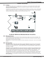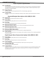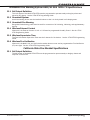
1
Installation Guide XT Series™ Panels MODEL XT30/XT50 XT SERIES™ INSTALLATION GUIDE FCC NOTICE This equipment has been tested and found to comply with the limits for a Class B digital device, pursuant to part 15 of the FCC Rules. These limits are designed to provide reasonable protection against harmful interference in a residential installation. This equipment generates, uses and can radiate radio frequency energy and, if not installed and used in accordance with the instructions, may cause harmful interference to radio communications. However, there is no guarantee that interference will not occur in a particular installation. If this equipment does cause harmful interference to radio or television reception, which can be determined by turning the equipment off and on, the user is encouraged to try to correct the interference by one or more of the following measures: • Reorient or relocate the receiving antenna. • Increase the separation between the equipment and receiver. • Connect the equipment into an outlet on a circuit different from that to which the receiver is connected. • Consult the dealer or an experienced radio/TV technician for help. Changes or modifications not expressly approved by the party responsible for compliance could void the user’s authority to operate the equipment. This device has been designed to operate with the 1100 Series antenna listed in the Accessory Devices section, and having a maximum gain of 1.8 dB. Antennas not included in this list or having a gain greater than 1.8 dB are strictly prohibited for use with this device. The required antenna impedance is 50 ohms. If necessary, the installer should consult the dealer or an experienced radio/television technician for additional suggestions. The installer may find the following booklet, prepared by the Federal Communications Commission, helpful: “How to identify and Resolve Radio-TV Interference Problems.” This booklet is available from the U.S. Government Printing Office, Washington D.C. 20402 Stock No. 004-000-00345-4 © 2008 Digital Monitoring Products, Inc. Information furnished by DMP is believed to be accurate and reliable. This information is subject to change without notice. Table of Contents Panel Specifications 1.1 1.2 1.3 1.4 1.5 1.6 1.7 Power Supply..........................................1 Communication........................................1 Panel Zones.............................................1 Keypads/Expansion..................................1 Number of Zones.....................................1 Outputs...................................................1 Enclosure Specifications...........................1 Introduction 2.1 2.2 2.3 System Configurations..............................2 Caution Notes..........................................2 Compliance Instructions...........................2 System Components 3.1 3.2 3.3 3.4 Wiring Diagram........................................3 Lightning Protection.................................3 Accessory Devices....................................3 XT30/XT50 Wiring Diagram......................4 Installation 4.1 4.2 4.3 Mounting the Enclosure............................5 Mounting Keypads...................................5 Installation Specifications.........................5 Primary Power Supply 5.1 5.2 AC terminals 1 and 2................................6 Transformer Types...................................6 Secondary Power Supply 6.1 6.2 6.3 6.4 6.5 6.6 6.7 Battery Terminals 3 and 4.........................7 Earth Ground...........................................7 Replacement Period.................................7 Discharge/Recharge.................................7 Battery Supervision..................................7 XT30/XT50 Power Requirements...............7 XT30/XT50 Standby Battery Calculations...8 Bell Output 7.1 Terminals 5 and 6....................................9 Keypad Data Bus 8.1 8.2 8.3 8.4 8.5 8.6 8.7 8.8 Description..............................................9 Terminal 7 - RED.....................................9 Terminal 8 - YELLOW...............................9 Terminal 9 - GREEN.................................9 Terminal 10 - BLACK................................9 Programming Connection.........................9 Keypad Addressing...................................9 OVC LED.................................................9 Smoke and Glassbreak Detector Output 9.1 Terminal 11...........................................10 Burglary Zones 10.1 10.2 10.3 10.4 XT30/XT50 Installation Guide Description............................................10 Operational Parameters..........................10 Zone Response Time..............................10 Keyswitch Arming Zone..........................10 Digital Monitoring Products i Table of Contents Powered Zone for 2-Wire Smoke Detectors 11.1 Terminals 25 and 26...............................11 Annunciator Outputs 12.1 12.2 12.3 Description............................................12 Harness Wiring......................................12 Model 860 Relay Module.........................12 Telephone RJ Connector 13.1 13.2 13.3 Description............................................13 FCC Registration....................................13 Notification............................................13 Ethernet Connector J1 14.1 14.2 Description............................................14 Ethernet LEDs.......................................14 Reset Jumper J16 15.1 Description............................................14 Flash Load Jumper J18 16.1 Description ...........................................14 Cellular Connections 17.1 Cellular ................................................15 On-Board 1100 Series Wireless Antenna Connection 18.1 18.2 Wireless Antenna ..................................15 LED Operation.......................................15 Listed Compliance Specifications 19.1 Introduction..........................................16 19.2 Bypass Reports......................................16 19.3 Current Draw.........................................16 Household Burglar-Alarm System Units ANSI/UL 1023 20.1 20.2 20.3 20.4 20.5 20.6 20.7 Bell Cutoff.............................................16 Entry Delay...........................................16 Exit Delay..............................................16 Wireless External Contact.......................16 Wireless Supervision Time......................16 Wireless Audible Annunciation................16 Panel location........................................16 Digital Burglar Alarm Communicator System Units ANSI/UL 1635 21.1 21.2 21.3 21.4 21.5 Entry Delay...........................................16 Exit Delay..............................................16 Test Frequency......................................16 Automatic Bell Test................................16 Central Station.......................................16 Household Fire Warning System ANSI/UL 985 NFPA 72 Specifications 22.1 22.2 22.3 22.4 22.5 22.6 Digital Monitoring Products ii Bell Output Definition.............................17 Household System.................................17 Household Fire Warning.........................17 Wireless External Contact.......................17 Wireless Supervision Time......................17 Wireless Fire Verification.........................17 XT30/XT50 Installation Guide Table of Contents California State Fire Marshal Specifications 23.1 Bell Output Definition.............................17 False Alarm Reduction Programmable Options ANSI/SIA CP-01-2007 24.1 24.2 24.3 24.4 24.5 Shipping Defaults and Programming........18 Call Waiting...........................................19 Entry Delay...........................................19 Local Bell..............................................19 Minimum Installation Requirements.........19 Troubleshooting 25.1 25.2 Troubleshooting Section.........................20 Common LCD Keypad Displays................20 Wiring Diagrams 26.1 Multiple Indicating Circuit Modules..........21 Listings and Approvals........................................22 XT30/XT50 Installation Guide Digital Monitoring Products iii Panel specifications Panel Specifications 1.1 Power Supply Transformer Input: Plug-in — 16.5 VAC 40 VA, Model 321 Wire-in — 16.5 VAC 40 VA, Model 320 Standby Battery: 12 VDC 7.7 Ah (40 VA transformer charges up to 2 batteries) Auxiliary Output: 12 VDC at 500mA Bell Output: 12 VDC at 1.5 Amps Smoke Detector Output: 12 VDC at 100mA All circuits inherent power limited Note: Please see NRTL (National Recognized Testing Laboratory) Listed Specifications section for a NRTL certificated application. 1.2 Communication Built-in Built-in Built-in Built-in 1.3 SDLC Digital Dialer communication to DMP Model SCS-1R Receivers network communication to DMP Model SCS-1R Receivers cellular communication to DMP Model SCS-1R Receivers CID (Contact ID) dialer communication to non-DMP receivers Panel Zones Nine 1k Ohm EOL burglary zones: zones 1 to 9 One 3.3k Ohm EOL Class B powered fire zone with reset capability: zone 10 1.4 Keypads/Expansion You can connect up to five supervised alphanumeric keypads. You can connect additional unsupervised keypads. • Security Command™, Thinline™, Aqualite™, Clear Touch™, and Icon keypads In addition, the following zone expanders can be added: • One, four, eight and 16-zone expansion modules • Single-zone PIR and glassbreak detectors 1.5 Number of Zones • • • • 1.6 Onboard zones 1-10 Five keypad bus addresses with zones 11-14, 21-24, 31-34, 41-44, and 51-54 (hardwired or wireless) Zone numbers 31 to 34 and 41 to 44 can support 1100 Series Key Fobs or DMP wireless output modules XT50 has 20 additional onboard wireless zones numbered 80-99 Outputs The XT30/XT50 panels provide four open collector outputs rated for 50mA each. A Model 300 Output Harness is required. The open collector outputs provide the ground connection for a positive voltage source. 1.7 Enclosure Specifications The XT30/XT50 panel ships standard in a 340 enclosure with EOL resistors, battery leads, user’s guide, and programming sheet. All enclosures are constructed using 20-gauge cold rolled steel. Enclosure Model Size Color 340 12.5” W x 9.5” H x 2.75” D Gray (G) 349 12.5” W x 11.25” H x 3.5” D Gray (G) XT30/XT50 Installation Guide Digital Monitoring Products 1 Introduction Introduction 2.1 System Configurations The panels can be programmed to operate as either an All/Perimeter system that provides one perimeter area and one interior area, or as a Home/Sleep/Away system that provides one perimeter, one interior, and one bedroom area. The bedroom area provides for any protection devices the user wants disarmed during their sleeping hours and armed in the Away mode. In addition, the XT30/XT50 can operate as a four area system. 2.2 Caution Notes Throughout this guide you will see caution notes containing information you need to know when installing the panel. These cautions are indicated with a yield sign. Whenever you see a caution note, make sure you completely read and understand its information. Failing to follow the caution note can cause damage to the equipment or improper operation of one or more components in the system. See the example shown below. Always ground the panel before applying power to any devices: The panel must be properly grounded before connecting any devices or applying power to the panel. Proper grounding protects against Electrostatic Discharge (ESD) that can damage system components. Remove All Power From the Panel! Remove all AC and Battery power from the panel before installing or connecting any modules, cards, or wires to the panel. 2.3 Compliance Instructions For applications that must conform to a local authorities installation standard or a National Recognized Testing Laboratory certificated system, please see the Listed Compliance Specifications section near the end of this guide for additional instructions. System Components 3.1 Wiring Diagram The system wiring diagram in Figure 1 on the following page, shows some of the accessory devices you can connect for use in various applications. A description of each module follows. 3.2 Lightning Protection Metal Oxide Varistors and Transient Voltage Suppressors help protect against voltage surges on input and output circuits. This transient protection provides additional resistance to electrical surges such as lighting. Additional surge protection is available by installing the DMP 370 or 370RJ Lightning Suppressors. Digital Monitoring Products 2 XT30/XT50 Installation Guide system components 3.3 Accessory Devices Zone and Output Expansion Modules 710 Bus Splitter/Repeater Increases keypad wiring distance to 2500 feet. 711 Single Point Zone Expander Provides one Class B zone for burglary devices and non-powered fire devices. 714, 714-8, 714-16 Zone Expander Provides Class B zones for burglary and non-powered fire devices. 712-8 Zone Expander Provides 8 zones for burglary devices. 715, 715-8, 715-16 Zone Expander Provides 12 VDC Class B powered zones for smoke detectors, glassbreak detectors, and other 2- or 4-wire devices. 860 Relay Output Module Provides one relay and three relay sockets for expansion of up to four relays. Interface Card 734 Wiegand Interface Card Provides arming, disarming, and codeless entry using access control readers. DMP Two-Way Wireless Devices 1100D/1100DH/1100DI Wireless Receiver Supports transmitters in residential or commercial wireless operation on the keypad bus. Only needed for XT30. 1100XTANT XT Wireless Antenna Provides a wireless antenna for the on-board 1100 receiver. 1101 Universal Transmitter Provides both internal and external contacts that may be used at the same time to yield two individual reporting zones from one wireless transmitter. 1102 Universal Transmitter Provides one external contact. 1114 Four-Zone Expander Provides four wireless zones with EOL resisters. 1116 Relay Output Provides one Form C relay. 1117 LED Annunciator Provides a visual system status indicator. 1121 PIR Motion Detector Provides motion detection with pet immunity. 1125 PIR Motion Detector Provides multiple lens configurations, dual coverage area selection, and sensitivity adjustments. 1129 Glassbreak Detector Detects the shattering of framed glass mounted in an outside wall and provides full-pattern coverage and false-alarm immunity. 1131 Recessed Contact Provides concealed protection for doors, windows or other applications. 1139 Bill Trap Provides a silent alarm option for retail and banking cash drawers. 1142BC Two-button Panic Belt Clip Transmitter Provides portable two-button panic operation. 1142 Two-button Panic Transmitter Provides permanently mounted under-the-counter two-button panic operation. 1145 (Four-Button) 1146 (Two-Button) 1147 (One-Button) Key Fob transmitters designed to clip onto a key ring or lanyard. 1161 Residential Smoke Detector Residential smoke detector with sounder. 1162 Residential Smoke Detector Residential smoke/heat detector with sounder and fixed rate-of-rise heat detector Keypads ePAD™ Virtual Keypads Allows users to control the security system from any computer in the world using the Internet. LCD keypads Allows you to control the panel from various remote locations. Connect up to five keypads. Model 690, 790, 693/793 Security Command™ keypads, 7060, 7063, 7070, 7073, 7160, 7163, 7170, 7173 Thinline™ keypads, 7060A, 7063A, 7070A, 7073A Aqualite™ keypads, 7360, 7363 Thinline Icon Series keypads, or 7760 Clear Touch™ keypad to the keypad bus using terminals 7, 8, 9, and 10. Cellular Antennas 384 Magnetic Mount Antenna Provides SMA Magnetic Mount Antenna for cellular connection. 385 Dual Band Smartdisc Antenna Provides SMA Dual Band Smartdisc Antenna for cellular connection. XT30/XT50 Installation Guide Digital Monitoring Products 3 system components 3.4 XT30/XT50 Wiring Diagram USE MARKING Commercial Burglary Control Unit (DACT) Household Fire and Burglary Warning System Control Unit. NFPA 72 This equipment should be installed in accordance with Chapter 11 of the National Fire Alarm Code, ANSI/NFPA 72-2002, (National Fire Protection Association, Batterymarch Park, Quincy, MA 02269). Printed information describing proper installation, operation, testing, maintenance, evacuation planning, and repair service is to be provided with this equipment. Warning: Ownerís instruction notice, not to be removed by anyone except occupant. TYPES OF SERVICE Suitable for DACT Central Station. Suitable for Household Fire and Household Burglary. Test weekly. SIA CP-01-2007 minimum system is J19 Celllular XT30/XT50 Antenna XT30 or XT50, local Bell, and off premise connection Command Processorô Panel DACT communication to an SCS-1R receiver plus ANSI/SIA CP-012007 classified compatible DMP keypads J7 RJ Supervision as indicated in the installation guide. DMP Transformers RED Programmer Header J8 Use DMP Model 330 Harness Plug into 120 VAC 60 Hz outlet not controlled by switch. s s AC Wiring must be in conduit and exit out the left side of the enclosure. Wiring on terminals 5 through 26 must exit right and maintain a 1/4" separation from the AC and battery positive wiring. J20 Wireless Antenna connection J11 1 2 3 4 Outputs J8 s Maximum AC Wire distance ñ 16 gauge wire: 70 feet 18 gauge wire: 40 feet s Bell Keypad Bus PROG Smoke Detector RED BLACK Smoke Switched Voltage Output s Zones 1 to 9 1K Ohm EOL on each zone To Keypad s or Zone Expander Zone 10 compatibility identifier: A Maximum operating range: 8.8 VDC - 14.2 VDC. Minimum voltage on Auxiliary output to process Sensor trips is 10.4 VDC. J16 Reset Terminals 5-20 are Power Limited. 16 to 18 gauge wire Bell ó 10.2 - 13.9 VDC Total current: 1.5 Amps max. w/ 40 VA AUX (RED) ó Up to 500mA auxiliary current at 10.2 13.9 VDC from Terminal 7 Smoke Output: ó 100mA at 10.2 - 13.9 VDC Terminal 11 POWER LIMITED All circuits on the Model XT30/XT50 comply with the requirements for inherent power limitation and are Class 2. J1 Ethernet J3 Phone Line Model 321 ñ 16.5 VAC 40 VA Class 2 plug-in. Model 320 ñ 16.5 VAC 40 VA Class 2 wire-in. HOUSEHOLD FIRE WIRING Recognized limited energy cable must be used for connection of all initiating, indicating, and supplementary devices. Listed Resistors 1.0k Ohm - DMP Model 311 3.3k Ohm - DMP Model 309 Zone 10 3.3K Ohm EOL Heat detectors, manual pull stations, or any other shorting device. Unlimited number of units. Verification Control Unit Zone Delay 10 13.6 sec. Smoke Model ______ Detector Delay ____sec. For Wireless Devices, Control Unit delay is 0 (zero). Cold Water Pipe Earth Ground Secondary Power Supply 1.2 Amps maximum charging current. Use only 12 VDC rechargeable batteries. Replace every 3 to 5 years. 1k Ohm For listed applications the maximum current from a combination of bell output, auxillary output, and smoke output is 1.6 amps. Figure 1: System Wiring Diagram Digital Monitoring Products 4 XT30/XT50 Installation Guide Installation Installation 4.1 Mounting the Enclosure The metal enclosure must be mounted in a secure, dry place to protect the panel from damage due to tampering or the elements. It is not necessary to remove the PCB when installing the enclosure. The PCB may be installed in the standard 340 small enclosure or in the optional 349 medium enclosure. Slide panel PCB into lower enclosure slots Model 349 Enclosure Slide panel PCB between formed metal supports Model 340 Enclosure J19 Celllular Antenna 65555 J7 RJ Supervision Enclosure Mounting Hole J3 Phone Line J24 Celllular header for 263G J8 RED Panel PCB screw J20 Wireless Antenna connection J18 Load J24 Celllular header for 263G J20 Wireless Antenna connection J18 Load J11 Outputs J1 Ethernet J8 RED 1 2 3 4 J16 Reset Programming Enclosure Mounting Hole J11 1 2 3 4 J16 Reset Programming 65555 J7 RJ Supervision J3 Phone Line Outputs J1 Ethernet J19 Celllular Antenna Enclosure Mounting Hole Panel PCB screw Panel PCB screw Panel PCB screw Dual 1/2" and 3/4" Conduit Knockout Dual 1/2" and 3/4" Conduit Knockouts Enclosure Mounting Holes Enclosure Mounting Holes Battery Shelf Battery Shelf Figure 2: Standard 340 Enclosure (left) or Optional 349 Enclosure (right) 4.2 Mounting Keypads DMP keypads have removable covers that allow the base to be mounted on a wall or other flat surface using the screw holes provided on each corner. For mounting keypads on solid walls, or for applications where conduit is required, use a DMP 695 or 696 keypad conduit backbox. 4.3 Installation Specifications Several factors determine the performance characteristics of the keypad bus: the length of wire used, the number of devices connected, and the voltage at each device. When planning a keypad bus installation, keep in mind the following four specifications: 1.DMP recommends using 18 or 22-gauge unshielded wire for all keypad circuits. Do not use twisted pair or shielded wire for keypad bus data circuits. 2.On keypad bus circuits, to maintain auxiliary power integrity when using 22-gauge wire do not exceed 500 feet. When using 18-gauge wire do not exceed 1,000 feet. To increase the wire length or to add devices, install an additional power supply. Note: Each panel allows a specific number of supervised keypads. Add additional keypads in the unsupervised mode. Refer to the panel installation guide for the specific number of supervised keypads allowed. 3.Maximum distance for any one bus circuit (length of wire) is 2,500 feet regardless of the wire gauge. This distance can be in the form of one long wire run or multiple branches with all wiring totaling no more than 2,500 feet. As wire distance from the panel increases, DC voltage on the wire decreases. 4.Maximum voltage drop between the panel (or auxiliary power supply) and any device is 2.0 VDC. If the voltage at any device is less than the required level, add an auxiliary power supply at the end of the circuit. When voltage is too low, the devices cannot operate properly. For additional information refer to the 710 Installation Sheet (LT-0310) and or the LX-Bus/Keypad Bus Wiring Application Note (LT-2031). XT30/XT50 Installation Guide Digital Monitoring Products 5 Installation Primary Power Supply 5.1 AC terminals 1 and 2 Connect the transformer wires to terminals 1 and 2 on the panel. Use no more than 70 ft. of 16 gauge, or 40 ft. of 18 gauge, wire between the transformer and the panel to deliver a minimum of 15.5 VAC when 500mA of current draw is used from the auxiliary power supply terminal 7. Always ground the panel before applying power to any devices: The panel must be properly grounded before connecting any devices or applying power to the panel. Proper grounding protects against Electrostatic Discharge (ESD) that can damage system components. See Earth ground, in the Secondary Power Supply section. 5.2 Transformer Types The transformer for the panel is 16.5 VAC 40 VA, which provides up to 1.5 Amps of bell output current, 500mA of auxiliary current, and 100mA of smoke detector output. You can use either the Model 320 wire-in or 321 plug-in transformer with the panel. The total current available is limited by the total battery standby requirements of the installation. The transformer must be connected to a 120 VAC 60 Hz commercial power outlet that is not controlled by a wall switch. Never share the transformer output with any other equipment. 5.3 Power LED When either AC transformer power or DC battery power is connected to the panel the PWR LED will show steady green. Digital Monitoring Products 6 XT30/XT50 Installation Guide Installation Secondary Power Supply 6.1 Battery Terminals 3 and 4 Connect the black battery lead to the negative battery terminal. The negative terminal connects to the enclosure ground internally through the XT30 or XT50 circuit board. Connect the red battery lead to the positive battery terminal. Observe polarity when connecting the battery. Add a second battery in parallel using the DMP Model 318 Dual Battery Harness. DMP requires each battery be separated by a PTC in the battery harness wiring to protect each battery from a reversal or short within the circuit. See Figure 3. Use sealed lead-acid batteries only: Use 12 VDC sealed lead-acid rechargeable battery. Batteries supplied by DMP have been tested to ensure proper charging with DMP products. GEL CELL BATTERIES CANNOT BE USED WITH THE XT30/XT50 PANEL. 6.2 XT30/XT50 Command Processor Panel AC AC +B –B BELL GND 1 To AC Red 318 Battery Harness Red 3 4 5 6 Panel Red and Black Battery Cables Black 14AWGto EarthGround PTC To Bell Circuit Black Battery 2 Battery Figure 3: Wiring Multiple Batteries Earth Ground Terminal 4 of the panel must be connected to earth ground using 14 gauge or larger wire to provide proper transient suppression. DMP recommends connecting to a metal cold water pipe or ground rod only. Do not connect to electrical conduit or a telephone company ground. 6.3 Replacement Period DMP recommends replacing the battery every 3 to 5 years under normal use. 6.4 Discharge/Recharge The panel battery charging circuit float charges at 13.9 VDC at a maximum current of 1.2 Amps using a 40 VA transformer. The total current available is reduced by the combined auxiliary current draw from terminals 7, 11, and 25. The various battery voltage levels are listed below: Battery Trouble: Battery Restored: 6.5 Below 11.9 VDC Above 12.6 VDC Battery Supervision The panel tests the battery once every hour when AC power is present. This test occurs 15 minutes past each hour and lasts for five seconds. A load is placed on the battery and if its voltage falls below 11.9 VDC a low battery is detected. If AC power has failed, a low battery is detected any time the battery voltage falls below 11.9 VDC. If a low battery is detected with AC power present, the test is repeated every two minutes until the battery charges above 12.6 VDC; the battery restored voltage. If a faulty battery is replaced with a fully charged battery, the restored battery will not be detected until the next two-minute test is done. 6.6 XT30/XT50 Power Requirements During AC power failure, the panel and all auxiliary devices connected draw their power from the battery. All devices must be taken into consideration when calculating the battery standby capacity. On the following page is a list of the power requirements of the panel. Add the additional current draw of DMP keypads, smoke detector output, and any other auxiliary devices used in the system for the total current required. The total is then multiplied by the total number of standby hours required to arrive at the total Ampere-hours required. XT30/XT50 Installation Guide Digital Monitoring Products 7 Installation 6.7 XT30/XT50 Standby Battery Calculations Standby Battery Power Calculations Alarm Current XT30 Panel XT50 Panel Built-in Network (additional current) Built-in Cellular (additional current) Active Zones 1-9 Active Zone 10 2-Wire Smoke Detectors Panel Bell Output x 125mA ______mA x 145mA ______ x 145mA ______ x 18mA ______ x 1.6mA ______ x 4mA ______ 0.1mA ______ 263G Digital Cellular Communicator x 1100D Wireless Receiver x 1100DH Wireless High Power Receiver 1100DI Wireless In-Line Receiver x 690 Security Command Keypad 693 Security Command Keypad 790 Security Command Keypad Active Zones (EOL Installed) 793 Security Command Keypad Active Zones (EOL Installed) 7060/7160 Thinline/7060A Aqualite Keypad 7063/7163 Thinline/7063A Aqualite Keypad 7360 Thinline Icon Keypad 7363 Thinline Icon Keypad 7070/7170 Thinline/7070A Aqualite Keypad Active Zones (EOL Installed) 7073/7173 Thinline/7073A Aqualite Keypad Active Zones (EOL Installed) 734 Wiegand Interface Module Active Zones (EOL Installed) 738A Ademco Wireless Interface Module x x x 708 Bus Extender Module (one pair) x 710 Bus Splitter/Repeater Module 714 Zone Expansion Modules Active Zones (EOL Installed) 712-8 Zone Expansion Module Active Zones (EOL Installed) 714-8, 714-16 Zone Expansion Module Active Zones (EOL Installed) 715 Zone Expansion Module Active Zones (EOL Installed) 2-Wire Smokes 715-8, 715-16 Zone Expansion Modules Active Zones (EOL Installed) 2-Wire Smokes Aux. Powered Devices on Terminals 7 and 11 Other than Keypads and Modules x x x x x x x x x x x 125mA 145mA 145mA 18mA *2mA 30mA 0.1mA Max. ______mA ______ ______ ______ ______ ______ ______ ______ Qty ______ Qty ______ Qty ______ 1500mA x x x x 18mA ______ Qty ______ x 40mA ______ Qty ______ x x 160mA ______ Qty ______ 160mA ______ Qty ______ 30mA ______ x x x x x x x x x x 30mA ______ 77mA 92mA 77mA 1.6mA 92mA 1.6mA 72mA 85mA 60mA 73mA 72mA 1.6mA 85mA 1.6mA 15mA 1.6mA 75mA ______ ______ ______ ______ ______ ______ ______ ______ ______ ______ ______ ______ ______ ______ ______ ______ ______ 20mA ______ 30mA 7mA 1.6mA 17mA 1.6mA 20mA 1.6mA 7mA 4mA .1mA 20mA 4mA .1mA ______ ______ ______ ______ ______ ______ ______ ______ ______ ______ ______ ______ ______ ______mA Qty Qty Qty Qty Qty Qty Qty Qty Qty Qty Qty Qty Qty Qty Qty Qty Qty ______ ______ ______ ______ ______ ______ ______ ______ ______ ______ ______ ______ ______ ______ ______ ______ ______ x x x x x x x x x x x x x x x x x Qty ______ x Qty Qty Qty Qty Qty Qty Qty Qty Qty Qty Qty x x x x x x x x x x x ______ ______ ______ ______ ______ ______ ______ ______ ______ ______ ______ Total Standby ______mA Total Standby______mA x number of Standby Hours ______ = needed ______mA Total Alarm + 18mA ______ 40mA ______ 84mA 120mA 84mA *2mA 120mA *2mA 87mA 100mA 67mA 80mA 87mA *2mA 100mA *2mA 15mA *2mA 75mA ______ ______ ______ ______ ______ ______ ______ ______ ______ ______ ______ ______ ______ ______ ______ ______ ______ 20mA ______ 30mA 7mA *2mA 17mA *2mA 20mA *2mA 7mA *30mA .1mA 20mA *30mA .1mA ______ ______ ______ ______ ______ ______ ______ ______ ______ ______ ______ ______ ______ ______mA Total Alarm ______mA ________mA-hours ________mA-hours ________mA-hours Total X .001 * Based on 10% of active zones in alarm condition. Digital Monitoring Products 8 = ________Amp-hrs Required XT30/XT50 Installation Guide Installation Bell Output 7.1 Terminals 5 and 6 Nominal 12 VDC is supplied by terminal 5 on the panel to power alarm bells or horns. The output is rated for a maximum of 1.5 Amps with a 40 VA transformer. This output can be steady, pulsed, or Temporal Code 3 depending upon the Bell Action specified in Output Options programming. Terminal 6 is the ground reference for the bell circuit. If using a horn or siren, a 1k 0hm resister should be added across the bell circuit for supervision. Keypad Data Bus 8.1 Description Terminals 7, 8, 9, and 10 of the panel are designated as the keypad data bus. In addition to keypads, the XT30/XT50 allows the connection of any combination of zone expansion modules, 5845LX Glassbreak Detectors, and 6155LX PIRs to the keypad bus up to the maximum of five devices. 8.2 Terminal 7 - RED Nominal 12 VDC is supplied at terminal 7 to power keypads and zone expanders. This is also where power for any auxiliary device is supplied. The ground reference for terminal 7 is terminal 10. The maximum output is rated at 500mA. All auxiliary devices totaled together must not exceed the Terminal 7 maximum current rating of 500mA. 8.3 Terminal 8 - YELLOW Data receive from keypads and zone expanders. 8.4 Terminal 9 - GREEN Data transmit to keypads and zone expanders. 8.5 Terminal 10 - BLACK Terminal 10 is the ground reference for LCD keypads, zone expanders, and any auxiliary devices being powered by terminals 7 and 11. 8.6 Keypad Bus LEDs The two LEDs located just above terminal 13 indicate keypad transmit data (XMIT) and keypad receive data (RCV). The bottom LED flashes green to indicate data being transmitted from the panel. The top LED flashes yellow to indicate data being received by the panel from keypads, zone expanders, etc. 8.7 Programming Connection A locking 4-pin header (J8) is provided to connect a keypad when using a DMP Model 330 Programming Cable. This provides a quick and easy connection for programming the panel. 8.8 Keypad Addressing Keypad Bus expansion zones are numbered in groups of four corresponding to the address. Example: address 1 is zones 11-14 and address 5 is zones 51-54. There are a maximum of 20 zones possible on the Keypad Bus. All keypad zones terminate with a 1k 0hm EOL resister. Address 1 2 3 4 5 XT30/XT50 Installation Guide XT30/XT50 Zone Number 11-14 21-24 31-34 41-44 51-54 Digital Monitoring Products 9 Installation 8.9 Overcurrent OVC LED The Overcurrent LED (OVC) lights Red when the devices connected to the Keypad Bus draw more current than the auxiliary output rating. The OVC LED is located above terminals 9 and 10 as shown in Figure 4. When the OVC LED lights Red, the Keypad bus/auxiliary power (terminal 7) and the Programming header (J8) shut down. J7 RJ Supervision J3 Phone Line OVC LED Smoke and Glassbreak Detector Output 9.1 Power LED Terminal 11 Nominal 12 VDC at 100mA maximum (shared by terminal 25) is supplied at terminal 11 to power 4-wire smoke detectors or other auxiliary powered devices. This output can be turned off by the user for 5 seconds using the Sensor Reset option in the User Menu. Terminal 10 is the ground reference for terminal 11. Figure 4: OVC LED location Burglary Zones 10.1 Description On XT30/XT50 panels, terminals 12 to 24 are the nine burglary zones. For programming purposes, the zone numbers are 1 to 9. The zone configurations on terminals 12 to 24 are described below. Terminal Function Terminal Function 12 Zone 1 voltage sensing 19 Ground for zones 5 & 6 13 Ground for zones 1 & 2 20 Zone 6 voltage sensing 14 Zone 2 voltage sensing 21 Zone 7 voltage sensing 15 Zone 3 voltage sensing 22 Ground for zones 7, 8, & 9 16 Ground for zones 3 & 4 23 Zone 8 voltage sensing 17 Zone 4 voltage sensing 24 Zone 9 voltage sensing 18 Zone 5 voltage sensing The voltage sensing terminal measures the voltage across the 1k Ohm End-of-Line resistor and the zone’s ground terminal. Dry contact sensing devices can be used in series (normally-closed) or in parallel (normally-open) with any of the burglary protection zones. 10.2 Operational Parameters Each burglary protection zone detects three conditions: open, normal, and short. The parameters for each are listed below: Condition Open Normal Short Resistance on zone over 1300 ohms 600 to 1300 ohms under 600 ohms 1K Ohm Normally Closed 1K Ohm Normally Open Voltage on zone terminal over 2.0 VDC 1.2 to 2.0 VDC under 1.2 VDC 1K Ohm Combination Normally Open and Normally Closed Figure 5: Protection Zone Contact Wiring Digital Monitoring Products 10 XT30/XT50 Installation Guide Installation 10.3 Zone Response Time A condition must be present on a zone for 500 milliseconds before it is detected by the panel. Ensure detection devices used on the protection zones are rated for use with this delay. 10.4 Keyswitch Arming Zone You can use a momentary keyswitch on a zone programmed as an Arming type for use in arming and disarming the system without a code. Powered Zone for 2-Wire Smoke Detectors 11.1 Terminals 25 and 26 A resettable 2-wire Class B powered zone is provided on terminals 25 (positive) and 26 (negative) of the panel. For programming purposes, the zone number is 10 on the XT30/XT50. The zone uses a Model 309, 3.3k Ohm EOL resistor (provided with the panel) and has an operating range of 8.8 to 13.9 VDC. The compatibility identifier is: A. Caution: Sensor reset on zone 10 will drop power to devices on this zone, causing the panel to sense an open condition on all zone types other than Fire, Fire Verify, and Supervisory. Whenever non-Fire and nonSupervisory zone types are used on zone 10, make the appropriate adjustments to the zone’s Armed Action to prevent false alarms from occurring. Manufacturer Model Detector ID Base Base ID # of Detectors Zone Expansion Modules Detection Systems DS250, DS250TH B MB2W, MB2WL A 10 715, 715-8, 715-16, 725 Detection Systems DS250HD B MB2W, MB2WL A 10 715, 715-8, 715-16 Detection Systems DS282, DS282TH B 10 715, 715-8, 715-16, 725 DMP/Hochiki SLK-835 HD-5 HSB-200, HSB-200N HB-55 7 715, 715-8, 715-16 DMP/Hochiki SLR-835 HD-3 NS6-100 HB-55 7 715, 715-8, 715-16, 725 DMP/Hochiki SLR-835B HD-6 7 715, 715-8, 715-16, 725 Sentrol/ESL 429AT, 521B, 521BXT S09A 12 715, 715-8, 715-16 XT30/XT50 Installation Guide Digital Monitoring Products 11 Installation Annunciator Outputs 12.1 Description The four annunciator outputs can be programmed to indicate the activity of the panel’s zones or conditions occurring on the system. Annunciator outputs do not provide a voltage but instead switch-to-ground voltage from another source. The outputs can respond to any of the conditions listed below: 1) 2) 3) 4) 5) Activation by zone condition: Steady, Pulse, Momentary, or Follower Manually from the keypad Communication failure Armed area annunciation Fire Alarm or Fire Trouble 6) Ambush alarm 7) Exit and Entry timers 8) System Ready 9) Late to Close 12.2 Harness Wiring The open collector outputs are accessible by installing the DMP 300 Harness on the 4-pin header labeled J11. The output locations are shown below. Output Color Wire 1 2 Red Yellow 1 2 Output Color Wire 3 4 Green Black 3 4 12.3 Model 860 Relay Module Connect a Model 860 Relay Module to the panel to provide relays for the annunciator outputs that can be used for electrical isolation between the alarm panel and other systems or for switching voltage to control various functions. The module includes one relay and provides three additional sockets for expansion of up to four relays. Power is supplied to the relay coils from the panel keypad bus. The 860 mounts inside the panel enclosure using the 3-hole mounting configuration. Plastic standoffs are provided with the module for ease of installation. A 4-wire harness is also provided that connects the Model 860 to the panel. Relay Contact Rating: 1 Amp at 30 VDC Digital Monitoring Products 12 XT30/XT50 Installation Guide Installation Telephone RJ Connector 13.1 Description Connect the panel to the public telephone network by installing a DMP 356 RJ Cable between the panel’s J3 connector and the RJ31X or RJ38X phone jack. A two pin header labeled RJ SUP (J7) is provided to allow monitoring of the telephone cable connected between the panel and a RJ38X jack (pins 2 and 7 jumpered). Attach a DMP Model 306 Harness between J7 and any available zone. The J7 pins are connected via the telephone cable to the RJ38X jack pins 2 and 7. The RJ38X jack provides a jumper between pins 2 and 7 which completes the circuit. Program the zone as a Supervisory type (SV). When the telephone cable is removed, the keypad displays zone trouble and produces a steady tone. To Telephone Line Ring Tip 5 4 6 3 7 2 1 8 To Premise Phone(s) Ring1 RJ31X or RJ38X Phone Block Tip 1 Figure 6: Phone Jack Wiring 13.2 FCC Registration The panel complies with FCC part 68 and is registered with the FCC. Registration number: CCKAL00BXT50 Ringer Equivalence: 0.0B 13.3 Notification Registered terminal equipment must not be repaired by the user. In case of trouble, the device must be immediately unplugged from the telephone jack. The factory warranty provides for repairs. Registered terminal equipment may not be used on party lines or in connection with coin telephones. Notification must be given to the telephone company with the following information: a. The particular line(s) the service is connected to b. The FCC registration number c. The ringer equivalence d. The make, model, and serial number of the device XT30/XT50 Installation Guide Digital Monitoring Products 13 Installation Flash Load Jumper J18 16.1 Description The XT Series panel software can be updated via the panel’s programming (PROG) header. To update the XT30/50 panel with a new software version, complete the following steps: 1. Place a jumper across the Reset (J16) header and then remove the yellow and green wires from keypad bus terminals 8 and 9. 2. Connect a DMP 399 Cable from the J8 Programming Header to the serial port of your PC operating Remote Link and containing the XT RU file. Requires Remote Link 1.43 or higher. 3. Start Remote Link and create or open the XT Series control panel account that matches the panel to be updated. 4. Set the Connection Information Type to Direct with a baud rate of 38400 and choose the appropriate COM port. 5. Select Panel>Remote Update, then select the correct RU file for the XT panel model. 6. While placing a short across the LOAD (J18) header, remove the jumper from the Reset (J16) header. Then remove the short from the LOAD header and click <Update> in Remote Link. 7. After the software version is updated, place the jumper across Reset (J16) then remove the 399 cable. 8. Replace the yellow and green wires to terminals 8 and 9. 9. Remove Reset (J16) jumper to resume normal panel operation. Digital Monitoring Products 14 XT30/XT50 Installation Guide Installation Cellular Connections 17.1 Cellular The XT30/XT50 Cellular option is available built-in at the factory or as an optional add-on module, Model 263G. The J19 SMA cellular antenna connector is provided for the built-in cellular version and protrudes through the top of the enclosure. If the panel is not purchased with built-in cellular, then the J24 header is provided to connect a 263G Digital Cellular Communicator as an add-on. The 263G Digital Cellular Communicator provides a cellular antenna connection that protrudes through the top of the enclosure similar to J19. 1100 Series Antenna (XT50) J19 Celllular Antenna connector 65555 Built-in Cellular Module J24 Celllular headerfor 263G connection J20 1100 Series Wireless Antenna connection WirelessLEDs TX RX J18 Load J1 Ethernet RCV Connect antenna to rightside only J11 1 2 3 4 Outputs J8 XMIT Programming J16 Reset Figure 9: Cellular and 1100 Series Wireless Antenna Connections On-Board 1100 Series Wireless Antenna Connection 18.1 Wireless Antenna The XT50 Wireless Antenna terminal block J20 is located at the top right corner of the circuit board. The antenna installs through a small opening in the top of the enclosure and is attached to the panel using the right terminal. The left terminal is not used. The XT50 built-in wireless operates with DMP 1100 Series transmitters. See section 3.4 for a list of accessory devices. 18.2 LED Operation Green (TX): With a wireless house code enabled, the green LED flashes every time the receiver transmits (32 times per second). If a house code is not programmed in the panel, the panel is reset, or the panel is powered off, the green LED will be off. Under normal operation, the green LED flashes constantly with no interruption or change. Yellow (RX): The yellow LED flashes every time the receiver hears a message from a programmed wireless transmitter. When a message is sent by a transmitter, typically by pressing or releasing the tamper switch, the yellow LED should flash indicating that the receiver received a message from the transmitter. If the LED never flashes, the transmitter is not getting through to the receiver. This could be because of a misprogrammed serial number or the transmitter is too far away. Under normal operation, the yellow LED will flash at every trip of every wireless transmitter and occasionally when the transmitters perform their periodic check-in. It is not unusual for this LED to stay off for many minutes at a time when no transmitters are communicating. XT30/XT50 Installation Guide Digital Monitoring Products 15 COMPLIANCE Listed Compliance Specifications 19.1 Introduction The programming and installation specifications contained in this section must be completed when installing the XT30/XT50 in accordance with any of the ANSI/UL burglary standards. Additional specifications may be required by a particular standard. 19.2 Bypass Reports The bypass reports must be programmed as YES for all listed burglary applications. 19.3 Current Draw The total current draw from a combination of auxiliary, smoke, and bell output terminals must not exceed 1.6 Amps. Household Burglar-Alarm System Units ANSI/UL 1023 20.1 Bell Cutoff The bell cutoff time cannot be less than four minutes. 20.2 Entry Delay The maximum entry delay used must not be more than 45 seconds. 20.3 Exit Delay The maximum exit delay used must not be more than 60 seconds. 20.4 Wireless External Contact When used, the External Contact of 1101 or 1102 must be programmed Normally Closed. 20.5 Wireless Supervision Time The Zone Information Supervision Time cannot be set to 0 (zero). 20.6 Wireless Audible Annunciation The Wireless Audible option must be selected as DAY for residential applications. 20.7 Panel location Mount panel inside protected area or have tamper switch installed on enclosure. Zone 1 may be programmed for Alarm on Tamper. Digital Burglar Alarm Communicator System Units ANSI/UL 1635 21.1 Entry Delay The maximum entry delay used must not be more than 60 seconds. 21.2 Exit Delay The maximum exit delay used must not be more than 60 seconds. 21.3 Test Frequency The Test Frequency option must be programmed to send a report once every 24 hours. 21.4 Automatic Bell Test This option must be programmed as YES. 21.5 Central Station Digital Dialer Central Station (DACT) service for commercial application can be provided under ANSI/UL 1635 by adding a listed local audible signal appliance and placing the XT30 or XT50 panel into the Model 350A Attack Resistant Enclosure. Digital Monitoring Products 16 XT30/XT50 Installation Guide COMPLIANCE Household Fire Warning System ANSI/UL 985 NFPA 72 Specifications 22.1 Bell Output Definition The bell output of the Model XT30/XT50 must be programmed to operate steady on burglary alarms and pulsed on fire alarms. See the XT30/XT50 Programming Guide. 22.2 Household System An alarm sounding device must be installed indoors so that it is clearly heard in all sleeping areas. 22.3 Household Fire Warning Recognized limited energy cable must be used for connection of all initiating, indicating, and supplementary devices. 22.4 Wireless External Contact When used, the External Contact of 1101 or 1102 must be programmed Normally Closed. See the XT30/ XT50 Programming Guide. 22.5 Wireless Supervision Time The Zone Information Supervision Time must be 3 minutes for fire devices. See the XT30/XT50 Programming Guide. 22.6 Wireless Fire Verification When used, the Model 1161 and 1162 wireless smoke detectors must not be programmed as Fire Verification (FV) zone type. See the XT30/XT50 Programming Guide. California State Fire Marshal Specifications 23.1 Bell Output Definition The bell output of the Model XT30/XT50 must be programmed to operate steady on burglary alarms and temporal on fire alarms. XT30/XT50 Installation Guide Digital Monitoring Products 17 COMPLIANCE False Alarm Reduction Programmable Options ANSI/SIA CP-01-2007 24.1 Shipping Defaults and Recommended Programming SIA CP-01 FEATURE PARAGRAPH # AND DESCRIPTION DMP PROGRAMMING GUIDE LT‑0981 SECTION # REQUIREMENT RANGE 4.2.2.1 Exit Time 8.6 Exit Delay Required 45 sec. - 250 sec. (Programmable) 4.2.2.2 Progress Annunciation 13.14 Prewarn Address Allowed 4.2.2.3 Exit Time Restart 8.6 Exit Delay Required Option 8.17 Occupied Premise - See Install Required Option Occupied Premise (except for NO/YES option remote arming) 4.2.2.5 Auto Stay Arm on Unvacated Premises Guide SHIPPING DEFAULT RECOMMENDED PROGRAMMING* 60 Seconds 60 Seconds Individual keypads may be disabled per zone All keypads enabled All keypads enabled For re-entry during exit time Enabled Enabled Enabled Enabled Yes for Residential Applications 4.2.4.4 Exit Time and Progress Annunciation/ Disable - for Remote Arm Not Available on Remote Arming Allowed Option 4.2.3.1 Entry Delay(s) 8.5 Entry Delay Required 30 sec. – 240 Sec. ** (Programmable) Progress Annunciation Not Always disabled for Available Remote Arming Disable by zone or zone type Remote Arming not allowed for CP-01 installations. 30 Seconds At least 30 Seconds ** Enabled NT DY EX Zone Enabled 4.2.5.1 Abort Window – 3.3 Transmit Delay for Non‑Fire Zones Required Option 4.2.5.1 Abort Window Time – for Non-Fire Zones 3.3 Transmit Delay Required 20 sec., 30 sec., or (Programmable) 40 sec. ** 30 Seconds At least 20 Seconds ** 4.2.5.1.2 Abort Annunciation 3.3 Transmit Delay Annunciate that Required Option no alarm was transmitted Yes Yes 4.2.5.4.1 Cancel Annunciation Annunciate that Always Enabled - Not Required Option a Cancel was Programmable transmitted (S49) Always Enabled Yes 4.2.6.1 & 4.2.6.2 Duress Feature User Code + 1 = Ambush Code Not Available 4.3.1 Cross Zoning Allowed Option No 1 + derivative of Code +1 another user code/no Always duplicates with other Disabled user codes Not Programmable 13.16 Cross Zone Required Option Yes/No Zone Programming No Enabled using two or more programmed zones 4.3.1 Programmable Cross Zoning Time 8.7 Cross Zone Time Allowed 4 sec. - 250 sec. 0 Seconds Per walk path in protected premises 4.3.2 Swinger Shutdown Not Available — Always On Required For all non-fire zones, shut down after 1 trip Always On Always On For non-police response zones Yes Enabled (all zones) No Yes as required (unless sensors can self verify) Disabled Enabled if user has call waiting 4.3.2 Swinger Shutdown 13.13 Swinger Bypass Allowed Disable 4.3.3 Fire Alarm Verification 13.5 Zone Type Required Option FV Type Zone 4.5 Call Waiting Cancel 3.17 First Telephone Number Required Option Include *70P in Telephone Number * Programming at installation may be subordinate to other listed requirements for the intended application. ** For listed Installations, combined Entry Delay and Transmit Delay should not exceed 1 minute. Digital Monitoring Products 18 XT30/XT50 Installation Guide COMPLIANCE False Alarm Reduction Programmable Options ANSI/SIA CP-01-2007 (continued) 24.2 Call Waiting The Call Waiting default setting is disabled. To cancel the Call Waiting feature, program * (star) 7 0 P (pause), the standard telephone code prefix that cancels call waiting, into the telephone number string. Cancel Call Waiting for telephone lines that have Call Waiting operational on the telephone line. See the XT30/XT50 Programming Guide. Caution: A call waiting cancel programmed on a non-call waiting telephone line, would prevent communication to the central station. 24.3 Entry Delay Only use Entry Delay 1. Do not use Entry Delay 2. See the XT30/XT50 Programming Guide. 24.4 Local Bell All non-fire zones such as Night, Day, Exit, Aux1 and Aux 2 must be programmed for local bell enabled with a bell cutoff time set to a minimum of 6 minutes to provide a cancel window of 5 minutes or greater. This does not apply to manually operated zone types such as Panic and Emergency. 24.5 Minimum Installation Requirements SIA CP-01-2007 minimum system installation requirements include an XT30 or XT50, a local Bell, and off premise DACT communication to an SCS-1R receiver plus one of the following compatible keypads. 690, 693, 790, 793 Security Command™ keypads 7060, 7063, 7070, 7073, 7160, 7163, 7170, or 7173 Thinline™ keypads 7060A, 7063A, 7070A, or 7073A Aqualite™ keypads 7360 or 7363 Thinline™ Icon keypads 7760 Clear Touch™ keypad XT30/XT50 Installation Guide Digital Monitoring Products 19 Troubleshooting 25.1 Troubleshooting Section Troubleshooting This section provides troubleshooting information for use when installing or servicing an XT30/XT50 system. Problem Possible Cause Keypad displays “SYSTEM TROUBLE” Keypad keyboard is not functional. When a key is pressed, only a short beep is emitted. Keypad XMIT Green LED is off Keypad RCV Yellow LED is off Possible Solutions J16 Jumper is installed. Remove the J16 reset jumper. Open or short on the green data wire to the keypad. Check for broken or shorted wires between the panel and the keypad. Bad keypad or zone expander is affecting the Green data wire. Replace keypad or zone expander. Open or short on the yellow data wire to the keypad. Check for broken or shorted wires between the panel and the keypad. Bad keypad or zone expander. is affecting the Yellow data wire. Replace keypad or zone expander. Panel is reset. Remove J16 jumper. Flash Load enabled. Remove J18 jumper and reset panel. Keypad/expanders are not connected to panel. Connect keypad/expanders. Keypad/expanders are greater than five. Check keypad/expanders address. Keypad beeps when keys are pressed, but will not allow the user to arm or disarm, or enter the User Menu. Two or more keypads are assigned to the same address. Set each keypad on the system to a unique address. Power LED is off. AC/Battery is not connected. Connect AC power and/or battery. Overcurrent OVC LED turns Red Too many devices attached to auxiliary. Maximum current draw is 500 mA. Wireless Green TX LED is off. Wireless House Code is not programmed. Program House Code in System Options. Wireless Yellow RX LED never flashes. Transmitters are not getting through to receiver. Wireless Green TX and Yellow RX LEDs are both on steady Keypad operates intermittently, keystrokes may be missed, or display does not update consistently. Check transmitter serial numbers. Move transmitter closer. If XT30, replace 1100 series receiver. Panel is reset. Remove J16 jumper. Flash Load enabled Remove J18 jumper and reset panel. Wire length may exceed maximum, resulting in poor data performance. Wire length can be reduced or a heavier gauge used. A power supply can be added near the keypad. Aee LT-2031, LX-Bus/Keypad Bus Wiring Application Note for more information. 25.2 Common LCD Keypad Displays Listed below are several keypad messages you may see on the display. Follow the instructions in the Possible Solutions column to correct the problem. Message Meaning Possible Solutions INVALID CODE The user code entered is not recognized by the system. Check the user code and try again. CLOSING TIME The system was not armed at its scheduled closing time. Users still on the premise should arm the system or extend the schedule to a later time. AC TROUBLE The system is not getting properAC power. Check that the AC connections are good from the transformer. BATTERY TROUBLE The battery is either low or missing. Check to see that battery and connections are good. SYSTEM BUSY The system is performing another task with a higher priority or is being Remote Programmed. Wait a few moments for the system to complete the task. Make sure the J16 jumper is not on the panel. If the message displays for several minutes, the keypad is not receiving polling from the panel. TRANSMIT FAIL The panel has attempted to communicate with the central station multiple times and has not succeeded. Verify your communication type, account number, and phone number. Make sure the telephone line is connected and working properly. Digital Monitoring Products 20 XT30/XT50 Installation Guide DMP Model 866 37mA at 12 VDC XT30/XT50 Installation Guide 1k Ω Bell T rouble Bell T rouble Bell B Ð Output Bell B + Output Bell A Ð Output 10 11 9 8 7 6 5 Bell A + Output - 4 Bell Power Ð Input 2 3 1 Bell Power + Input Alarm Input Ground Auxiliary Power Power Supply Trouble Contacts N/C AUXILIARY POWER SUPPLY 8 7 6 5 4 3 2 1 S S S S S S S DMP Model 865 85mA at 12 VDC S S S S S S 12 or 24 VDC 5 Amp Maximum Notification Circuit Module 12 or 24 VDC 5 Amp Maximum Bell T rouble Bell T rouble Bell Output - Bell Output + Bell Power Input Alarm Input Ground Auxiliary Power Notification Circuit Module Style W AUXILIARY POWER SUPPLY Power Supply Trouble Contacts N/C NOTE: If an auxiliary supply is not used, terminals 3 and 4 on the 866 Indicating Circuit Module can be jumpered together to supply bell power from the XT30 panel. Each 865 Notification Circuit Module in alarm draws up to 85mA from its terminal 3 alarm input. UL Listed, Polarized Indicating Devices. Style Z Each 866 Indicating Circuit Module in alarm draws up to 35mA from its terminal 3 alarm input. UL Listed, Polarized notification Devices. 10k Ω EOL Resistor DMP Model 308 Optional Module installation S S J3 PhoneLine J8 Programming RED S = Supervised Circuit J1 Ethernet 65555 S S J24 Celllular headerfor 263G connection The Auxiliary Power Supply and Indicating Circuit Module trouble contact zone must be programmed as a Supervisory Type zone and must be selected for display in the keypad status list. S J7 RJ Supervision J19 Celllular Antenna connection J16 Reset J18 Load J11 1 2 3 4 Outputs J20 Wireless Antenna connection Wiring Diagrams Wiring Diagrams 26.1 Multiple Indicating Circuit Modules Installation Digital Monitoring Products 21 800-641-4282 INTRUSION • FIRE • ACCESS • NETWORKS www.dmp.com 2500 North Partnership Boulevard Made in the USA Springfield, Missouri 65803-8877 8274 California State Fire Marshal (CSFM) ETL: ANSI/SIA CP-01 False Alarm Reduction ANSI/UL 1023 Household Burglar ANSI/UL 985 Household Fire Warning ANSI/UL 1635 Digital Burglar FCC Part 15 ID: CCKPC0096 FCC Part 68 Registration ID CCKAL00BXT50 Industry Canada ID: 5251A-PC0096 LT-0980 1.01 © 2008 Digital Monitoring Products, Inc. Listings and Approvals