1
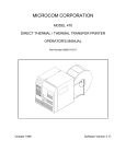
MICROCOM CORPORATION
MODEL 465
DIRECT THERMAL / THERMAL TRANSFER PRINTER
OPERATOR'S MANUAL
Part Number 880011-0131
August 1995
Software Version 1.31
Operator's Manual
465 Direct Thermal/Thermal Transfer Printer
- Revised 08/16/95 MSG -
Centronics is a registered trademark of Data Computer Corporation.
HP and LaserJet II are trademarks of Hewlett-Packard Company.
Comstar and I.D. Images are trademarks of Comstar Incorporated.
FastFont is a trademark of Page Technology Marketing, Inc.
Other products, names, and brands are trademarks of their respective holders.
FastFont Typefaces are Copyright © 1993, Page Technology Marketing, Inc.
This manual is subject to change without notice.
Copyright © 1993-1994, Microcom Corporation, Westerville, Ohio - All rights reserved.
Printed in the U.S.A.
Table of Contents
List of Tables
. . . . . . . . . . . . . . . . . . . . . . . . . . . . . . . . . . . . . . . . . . . . . . . . . . . . . . . . . . . . . . . . . . vi
List of Figures . . . . . . . . . . . . . . . . . . . . . . . . . . . . . . . . . . . . . . . . . . . . . . . . . . . . . . . . . . . . . vi
Introduction . . . . . . . . . . . . . . . . . . . . . . . . . . . . . . . . . . . . . . . . . . . . . . . . . . . . . . . . . . . . . . . . 1
CHAPTER 1: FEATURES AND SPECIFICATIONS . . . . . . . . . . . . . . . . . . . . . . . . . . . . . . . . . 3
1.1
SPECIAL FEATURES . . . . . . . . . . . . . . . . . . . . . . . . . . . . . . . . . . . . . . . . . . . . 3
1.2
BAR CODES . . . . . . . . . . . . . . . . . . . . . . . . . . . . . . . . . . . . . . . . . . . . . . . . . . . 4
1.3
FONTS . . . . . . . . . . . . . . . . . . . . . . . . . . . . . . . . . . . . . . . . . . . . . . . . . . . . . . . 4
1.4
PRINTING . . . . . . . . . . . . . . . . . . . . . . . . . . . . . . . . . . . . . . . . . . . . . . . . . . . . . 4
1.5
INTERFACE COMMUNICATIONS . . . . . . . . . . . . . . . . . . . . . . . . . . . . . . . . . . . 4
1.6
PHYSICAL . . . . . . . . . . . . . . . . . . . . . . . . . . . . . . . . . . . . . . . . . . . . . . . . . . . . . 5
1.7
ENVIRONMENT . . . . . . . . . . . . . . . . . . . . . . . . . . . . . . . . . . . . . . . . . . . . . . . . 5
1.8
ELECTRICAL . . . . . . . . . . . . . . . . . . . . . . . . . . . . . . . . . . . . . . . . . . . . . . . . . . . 5
1.9
OPTIONS . . . . . . . . . . . . . . . . . . . . . . . . . . . . . . . . . . . . . . . . . . . . . . . . . . . . . 5
1.10 APPROVALS . . . . . . . . . . . . . . . . . . . . . . . . . . . . . . . . . . . . . . . . . . . . . . . . . . . 5
CHAPTER 2: BASIC OPERATION . . . . . . . . . . . . . . . . . . . . . . . . . . . . . . . . . . . . . . . . . . . . . . 7
2.1
UNPACKING THE 465 PRINTER . . . . . . . . . . . . . . . . . . . . . . . . . . . . . . . . . . . 7
2.2
MOUNTING THE LABEL SUPPLY RACKS . . . . . . . . . . . . . . . . . . . . . . . . . . . . 7
2.3
INITIAL POWER UP . . . . . . . . . . . . . . . . . . . . . . . . . . . . . . . . . . . . . . . . . . . . . 7
2.4
FRONT PANEL KEYPAD AND STATUS DISPLAY . . . . . . . . . . . . . . . . . . . . . . 8
2.4.1 LABEL PRINT KEY . . . . . . . . . . . . . . . . . . . . . . . . . . . . . . . . . . . . . . . . 8
2.4.2 LINE FEED KEY . . . . . . . . . . . . . . . . . . . . . . . . . . . . . . . . . . . . . . . . . . 8
2.4.3 ON/OFF LINE KEY . . . . . . . . . . . . . . . . . . . . . . . . . . . . . . . . . . . . . . . . 9
2.5
THE STATUS LIGHTS/TONE . . . . . . . . . . . . . . . . . . . . . . . . . . . . . . . . . . . . . . 9
2.6
LOADING PAPER . . . . . . . . . . . . . . . . . . . . . . . . . . . . . . . . . . . . . . . . . . . . . . . 9
2.6.1 NORMAL AND TAG/TEAR MODES . . . . . . . . . . . . . . . . . . . . . . . . . . 10
2.6.2 PEEL-AND-DISPENSE MODE . . . . . . . . . . . . . . . . . . . . . . . . . . . . . . 10
2.7
CLEANING INSTRUCTIONS . . . . . . . . . . . . . . . . . . . . . . . . . . . . . . . . . . . . . . 11
CHAPTER 3: COMMUNICATIONS . . . . . . . . . . . . . . . . . . . . . . . . . . . . . . . . . . . . . . . . . . . . . 13
3.1
CABLE PINOUT . . . . . . . . . . . . . . . . . . . . . . . . . . . . . . . . . . . . . . . . . . . . . . . . 13
3.2
PRINTER CABLES . . . . . . . . . . . . . . . . . . . . . . . . . . . . . . . . . . . . . . . . . . . . . 14
CHAPTER 4: DESIGNING LABELS USING LDS . . . . . . . . . . . . . . . . . . . . . . . . . . . . . . . . . .
4.1
CONTROL CHARACTERS . . . . . . . . . . . . . . . . . . . . . . . . . . . . . . . . . . . . . . .
4.2
GETTING STARTED . . . . . . . . . . . . . . . . . . . . . . . . . . . . . . . . . . . . . . . . . . . .
4.2.1 PC CONNECTION (SERIAL) . . . . . . . . . . . . . . . . . . . . . . . . . . . . . . . .
4.2.2 PC CONNECTION (PARALLEL) . . . . . . . . . . . . . . . . . . . . . . . . . . . . .
4.2.3 LEARNING LDS . . . . . . . . . . . . . . . . . . . . . . . . . . . . . . . . . . . . . . . . . .
4.3
FORMATTING LABELS: AN OVERVIEW . . . . . . . . . . . . . . . . . . . . . . . . . . . .
4.4
LABEL HEADER . . . . . . . . . . . . . . . . . . . . . . . . . . . . . . . . . . . . . . . . . . . . . . .
4.4.1 A SAMPLE SESSION (HEADER) . . . . . . . . . . . . . . . . . . . . . . . . . . . .
4.5
LABEL FIELDS . . . . . . . . . . . . . . . . . . . . . . . . . . . . . . . . . . . . . . . . . . . . . . . .
4.5.1 BIT MAPPED TEXT AND BARCODE FIELDS . . . . . . . . . . . . . . . . . . .
15
15
15
15
16
17
17
19
24
25
25
4.5.2
4.5.3
4.5.4
GRAPHIC IMAGE FIELDS . . . . . . . . . . . . . . . . . . . . . . . . . . . . . . . . . . 31
LINES/RECTANGLES . . . . . . . . . . . . . . . . . . . . . . . . . . . . . . . . . . . . . 33
A SAMPLE SESSION (FIELDS) . . . . . . . . . . . . . . . . . . . . . . . . . . . . . . 35
CHAPTER 5: PRINTER COMMANDS . . . . . . . . . . . . . . . . . . . . . . . . . . . . . . . . . . . . . . . . . .
5.1
SPECIAL PRINTER CONTROL CODES . . . . . . . . . . . . . . . . . . . . . . . . . . . . .
5.2
PRINTER ENQUIRIES . . . . . . . . . . . . . . . . . . . . . . . . . . . . . . . . . . . . . . . . . . .
5.3
SENDING ^D PRINTER COMMANDS . . . . . . . . . . . . . . . . . . . . . . . . . . . . . . .
5.3.1 SOFTWARE SWITCHES/BATTERY BACKED COMMANDS . . . . . . .
5.3.2 PRINTING COMMANDS . . . . . . . . . . . . . . . . . . . . . . . . . . . . . . . . . . .
5.3.3 AUTOSIZING AND VALID GAP COMMANDS . . . . . . . . . . . . . . . . . . .
5.3.4 REAL-TIME CLOCK . . . . . . . . . . . . . . . . . . . . . . . . . . . . . . . . . . . . . .
5.3.5 SERIAL NUMBER COMMANDS . . . . . . . . . . . . . . . . . . . . . . . . . . . . .
5.3.6 LABEL HEADER COMMANDS . . . . . . . . . . . . . . . . . . . . . . . . . . . . . .
5.3.7 SAVED FORMAT FILE COMMANDS . . . . . . . . . . . . . . . . . . . . . . . . .
5.3.8 LABEL PRESENCE SENSOR CONTROL . . . . . . . . . . . . . . . . . . . . . .
5.3.9 TEXT STRINGS COMMANDS . . . . . . . . . . . . . . . . . . . . . . . . . . . . . . .
5.3.10 MISCELLANEOUS PRINTER COMMANDS . . . . . . . . . . . . . . . . . . . .
37
38
39
40
40
47
48
50
51
54
55
57
58
61
CHAPTER 6: GRAPHIC IMAGES . . . . . . . . . . . . . . . . . . . . . . . . . . . . . . . . . . . . . . . . . . . . . .
6.1
PROCEDURE FOR USING MICROCOM PCX2465 SOFTWARE . . . . . . . . . .
6.2
FORMAT OF GRAPHICS FILES . . . . . . . . . . . . . . . . . . . . . . . . . . . . . . . . . . .
6.3
GRAPHIC IMAGE COMMAND SUMMARY . . . . . . . . . . . . . . . . . . . . . . . . . . .
63
63
64
66
CHAPTER 7: SPECIAL DESIGNS . . . . . . . . . . . . . . . . . . . . . . . . . . . . . . . . . . . . . . . . . . . . .
7.1
DESIGNING WITH BARCODES . . . . . . . . . . . . . . . . . . . . . . . . . . . . . . . . . . .
7.1.1 HUMAN READABLES . . . . . . . . . . . . . . . . . . . . . . . . . . . . . . . . . . . . .
7.2
REVERSE VIDEO . . . . . . . . . . . . . . . . . . . . . . . . . . . . . . . . . . . . . . . . . . . . . .
67
67
68
69
CHAPTER 8: SOFT FONTS . . . . . . . . . . . . . . . . . . . . . . . . . . . . . . . . . . . . . . . . . . . . . . . . . . 71
CHAPTER 9: OPTIONS . . . . . . . . . . . . . . . . . . . . . . . . . . . . . . . . . . . . . . . . . . . . . . . . . . . . .
9.1
MICROCOM GRAPHICS CONVERSION UTILITIES . . . . . . . . . . . . . . . . . . . .
9.2
MICROCOM SOFT FONT UTILITY . . . . . . . . . . . . . . . . . . . . . . . . . . . . . . . . .
9.3
ADDITIONAL SOFT FONTS . . . . . . . . . . . . . . . . . . . . . . . . . . . . . . . . . . . . . .
9.4
WYSIWYG SOFTWARE PACKAGES . . . . . . . . . . . . . . . . . . . . . . . . . . . . . . .
9.5
CLEANING KIT . . . . . . . . . . . . . . . . . . . . . . . . . . . . . . . . . . . . . . . . . . . . . . . .
73
73
73
73
73
74
APPENDIX A: WARRANTY AND REPAIR PROCEDURES . . . . . . . . . . . . . . . . . . . . . . . . . . 75
APPENDIX B: MORE LABEL SAMPLES . . . . . . . . . . . . . . . . . . . . . . . . . . . . . . . . . . . . . . . .
POSTNET . . . . . . . . . . . . . . . . . . . . . . . . . . . . . . . . . . . . . . . . . . . . . . . . . . . . . . . . . .
BARCODES . . . . . . . . . . . . . . . . . . . . . . . . . . . . . . . . . . . . . . . . . . . . . . . . . . . . . . . .
FONTS 465 . . . . . . . . . . . . . . . . . . . . . . . . . . . . . . . . . . . . . . . . . . . . . . . . . . . . . . . . .
76
76
76
79
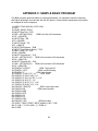
APPENDIX C: SAMPLE BASIC PROGRAM . . . . . . . . . . . . . . . . . . . . . . . . . . . . . . . . . . . . . . 82
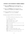
APPENDIX D: QUICK REFERENCE COMMAND SUMMARY . . . . . . . . . . . . . . . . . . . . . . . . 83
APPENDIX E: HARDWARE DIP SWITCHES . . . . . . . . . . . . . . . . . . . . . . . . . . . . . . . . . . . . . 95
Index . . . . . . . . . . . . . . . . . . . . . . . . . . . . . . . . . . . . . . . . . . . . . . . . . . . . . . . . . . . . . . . . . . . . 96
List of Tables
Status Light . . . . . . . . . . . . . . . . . . . . . . . . . . . . . . . . . . . . . . . . . . . . . . . . . . . . . . . . . . . . . . . . 9
Serial Port Configuration . . . . . . . . . . . . . . . . . . . . . . . . . . . . . . . . . . . . . . . . . . . . . . . . . . . . . 13
Parallel Port Configuration . . . . . . . . . . . . . . . . . . . . . . . . . . . . . . . . . . . . . . . . . . . . . . . . . . . 14
Print Speed . . . . . . . . . . . . . . . . . . . . . . . . . . . . . . . . . . . . . . . . . . . . . . . . . . . . . . . . . . . . . . . 22
Bitmapped Font Descriptions . . . . . . . . . . . . . . . . . . . . . . . . . . . . . . . . . . . . . . . . . . . . . . . . . 27
Barcode Symbologies . . . . . . . . . . . . . . . . . . . . . . . . . . . . . . . . . . . . . . . . . . . . . . . . . . . . . . . 28
Character Starting Positions . . . . . . . . . . . . . . . . . . . . . . . . . . . . . . . . . . . . . . . . . . . . . . . . . . 29
Enquiry Responses . . . . . . . . . . . . . . . . . . . . . . . . . . . . . . . . . . . . . . . . . . . . . . . . . . . . . . . . . 39
Clock Field Parameters . . . . . . . . . . . . . . . . . . . . . . . . . . . . . . . . . . . . . . . . . . . . . . . . . . . . . . 50
List of Figures
Front View . . . . . . . . . . . . . . . . . . . . . . . . . . . . . . . . . . . . . . . . . . . . . . . . . . . . . . . . . . . . . . . . . 6
Rear View . . . . . . . . . . . . . . . . . . . . . . . . . . . . . . . . . . . . . . . . . . . . . . . . . . . . . . . . . . . . . . . . . 6
Printer Parts . . . . . . . . . . . . . . . . . . . . . . . . . . . . . . . . . . . . . . . . . . . . . . . . . . . . . . . . . . . . . . . 7
Keypad Layout . . . . . . . . . . . . . . . . . . . . . . . . . . . . . . . . . . . . . . . . . . . . . . . . . . . . . . . . . . . . . 8
Printer Feed Mechanism . . . . . . . . . . . . . . . . . . . . . . . . . . . . . . . . . . . . . . . . . . . . . . . . . . . . . 10
Microcom Label . . . . . . . . . . . . . . . . . . . . . . . . . . . . . . . . . . . . . . . . . . . . . . . . . . . . . . . . . . . . 18
Label Header Parameters of a 4" X 3" Label . . . . . . . . . . . . . . . . . . . . . . . . . . . . . . . . . . . . . . 20
Lines . . . . . . . . . . . . . . . . . . . . . . . . . . . . . . . . . . . . . . . . . . . . . . . . . . . . . . . . . . . . . . . . . . . . 34
Status Label . . . . . . . . . . . . . . . . . . . . . . . . . . . . . . . . . . . . . . . . . . . . . . . . . . . . . . . . . . . . . . 61
Four Graphic Images . . . . . . . . . . . . . . . . . . . . . . . . . . . . . . . . . . . . . . . . . . . . . . . . . . . . . . . 63
Barcode Rotations . . . . . . . . . . . . . . . . . . . . . . . . . . . . . . . . . . . . . . . . . . . . . . . . . . . . . . . . . 67
Barcode Human Readables . . . . . . . . . . . . . . . . . . . . . . . . . . . . . . . . . . . . . . . . . . . . . . . . . . 68
Reverse Video . . . . . . . . . . . . . . . . . . . . . . . . . . . . . . . . . . . . . . . . . . . . . . . . . . . . . . . . . . . . 69
Introduction
The Microcom 465 is a Direct Thermal or Thermal Transfer label printer with a high resolution (832
dots or 8 dots/mm), 4.09 inch wide print head. The printer has the ability to handle a wide variety of
labeling tasks - even the most demanding applications.
The resident Label Design Software (LDS) is a powerful and easy-to-use package that allows you
to create personalized label formats. It can be driven from a PC, mini-computer, mainframe, and
most special purpose computers.
Among many other features, LDS supports graphics functions and multiple serial numbering. It
offers virtually unlimited text font sizes and all popular barcode symbologies. Graphic images can
be printed or stored in the printer's memory for future use. Bitmapped Fonts, barcodes, and graphic
images can be multiplied in size and printed in 0,90,180,270 degree rotations. Once the labels are
designed, they can be stored in the 465's memory for high speed printer access.
The 465 is capable of printing on most types of label stock or fax paper. It offers operation in a
tag/tear, peel-and-dispense, batch mode, and user-defined advance mode. It can handle blowhole, black-line, label gap, and continuous stock.
Many printer applications use the same label format, but change the data on every label. This is not
a problem for the Microcom 465 printer. Data may be changed without down-loading the same
fixed format, or fixed data fields, time after time. This, along with a greatly increased
communication speed, increases data access time and productivity.
Microcom also offers a complete line of software packages which allow quick and easy on-screen
label designing, along with complete database capabilities.
2
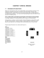
CHAPTER 1: FEATURES AND SPECIFICATIONS
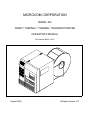
The Microcom 465 Direct Thermal/Thermal Transfer printer is designed with many standard
features that are unique when compared to other printers. The 465 is built to meet the demands of
complicated applications and rigorous use. A guarantee of excellence in engineering is provided by
fulfilling the requirements for approval by UL, CSA and the FCC.
1.1
SPECIAL FEATURES
!
Both Direct Thermal and Thermal Transfer modes
!
Operates as tag or ticket feed
!
Resolution of 8 dots/mm (.0049" per dot) and a print width of 832 dots (4.09")
!
WYSIWYG software compatible
!
Print speed up to 6.0 inches per second
!
Large media supply rack allows roll size up to 10 inches OD
!
Prints on die-cut, continuous, fax, or preprinted labels
!
Prints on tag stock up to 9.0 mil thickness
!
Software-controlled contrast adjustment
!
Standard memory of 512Kbytes ROM and 512Kbytes SRAM
!
Internal date and time keeping
!
Easy to load label path to prevent label jams or misfeeds
!
Detects label gap, black line, or blow-hole stock
!
Internal statistical counter for inches and labels printed
!
Graphics and Soft Font capability
!
Incrementing and decrementing fields
!
Machine state enquiries for security and maintenance
3
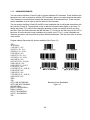
1.2
BAR CODES
!
Code 39, Interleaved 2 of 5, CODABAR, Code 128, Code 93, Plessey, Modified Plessey,
UPC-A, UPC-E, EAN-8, EAN-13, Postnet, MAXICODE, and selectable ratios for producing
HIBC, AIAG, and Logmars
!
Barcodes may be printed in 0, 90, 180, and 270 degree rotations
1.3
FONTS
!
Downloadable HP LaserJet II™ soft font compatibility and 16 resident bit mapped font
styles, including OCR-A.
!
All Bit Mapped fonts expandable in height and width up to 8 times
!
Fonts and Barcodes can be printed in 0, 90, 180, and 270 degree rotations
1.4
PRINTING
!
Peel function strips label off of backing
!
Tag/tear mode advances label to the tear bar
!
Batch mode printing
!
User defined label advancement for special stock or application
!
Label-presence sensor allows printer to dispense at the operator's pace
!
Label back-up prevents wasted media in tag/tear and peel modes
1.5
INTERFACE COMMUNICATIONS
!
Serial: RS-232C, 25-pin female D-Sub connector (DCE) and 2Kbytes buffer
-Flow control: XON/XOFF, CTS
-Baud rate: 300 to 38400, user-selectable
-Parity: odd, even or none
-Data bits: 7 or 8
!
Parallel (Optional): 36-pin female Centronics® connector and 2Kbytes buffer
4
1.6
PHYSICAL
!
Construction: Rigid painted steel with high impact molded front panel
!
Height: 11.00" (279.4mm)
!
Width: 10.125" (257.2mm)
!
Depth: 10.10" (256.5mm)
!
Weight: 35 LBS (15.89 K/g)
1.7
ENVIRONMENT
!
Temperature: 0" C to 40" C operating
!
Humidity: 10-90% non-condensing
1.8
ELECTRICAL
!
Voltage: Switchable 100,110,120,220,240VAC nom., 50-60 Hz.
!
Current: 3 Amps maximum (100VAC)
1.9
OPTIONS
!
Cleaning Kit
!
Assorted Printer Cables
!
On-screen label design PC software packages
!
PCX to printer graphics conversion PC software
!
PCX to downloadable bitmap PC software
!
Downloadable soft fonts
1.10 APPROVALS
!
UL, CSA, Complies with FCC, Class A
5
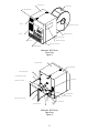
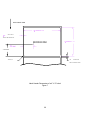
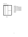
LEFT SIDE COVER
PAPER SUPPLY
LEFT SIDE FRONT PANEL
DISPLAY
PAPER SUPPLY HOLDER
KEYPAD
PAPER SUPPLY RACK
RIGHT SIDE COVER
PAPER SLOT
RIBBON VIEW WINDOW
RIGHT SIDE FRONT PANEL
BACKING PAPER SLOT
Microcom 465 Printer
Front View
Figure 1
RIGHT SIDE COVER
LEFT SIDE COVER
RACK THUMB SCREW
LEFT PAPER SUPPLY RACK
SERIAL PORT
PAPER SUPPLY HOLDER
POWER SWITCH
POWER ENTRY MODULE
RIGHT PAPER SUPPLY RACK
POWER CORD
PAPER LINE GUIDE
Microcom 465 Printer
Rear View
Figure 2
6
CHAPTER 2: BASIC OPERATION
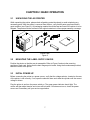
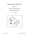
2.1
UNPACKING THE 465 PRINTER
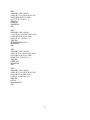
While unpacking the printer, please check all packing materials closely to avoid misplacing any
necessary parts. After the printer is removed from the box, verify that all parts are present and in
good condition (see Figure 3). All packaging material should be kept and used if the printer is to be
shipped. The printer must be returned in the original container to insure proper warranty coverage.
Printer Parts
Figure 3
2.2
MOUNTING THE LABEL SUPPLY RACKS
Position the printer so that the rear is assessable. Refer to Figure 2 and note the mounting
positions of each rack. Notice that the bent flanges point inward. Using the thumbscrews provided,
attach the racks to the printer.
2.3
INITIAL POWER UP
Before connecting the printer to a power source, verify that the voltage selector, located on the rear
of the printer, is set correctly. If not, open the selection door and rotate the cylinder until the correct
voltage is shown.
Plug the printer in and turn the power switch on. The green power indicator should light. The
motors will then adjust tension and a tone will be heard. If this does not occur, check the power
source and if necessary call your service organization.
7
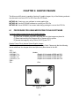
2.4
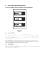
FRONT PANEL KEYPAD AND STATUS DISPLAY
The front panel contains a three button keypad and a three LED status display.
Keypad Layout
Figure 4
2.4.1
LABEL PRINT KEY
The front panel keypad (see figure 4) contains a 'LABEL PRINT' key. If this key is pressed the unit
will print the currently loaded label format or the default label if no format has been loaded. If the
printer is in the process of printing a predetermined quantity of labels (see ^D73, section 5.3),
pressing the 'LABEL PRINT' key will pause the printer. Pressing the key again will allow the printer
to continue the batch.
If the 'LABEL PRINT' key is depressed when the power is turned on, the printer is put into test
mode and a statistics and test label will be printed (see ^D29 chapter 5.3.10). This test mode is
also useful to temporarily set all software dip switches to default.
2.4.2
LINE FEED KEY
Pressing and holding the 'LINE FEED' key will cause the printer to advance until released. This key
can be use to load and align paper stock.
8
2.4.3
ON/OFF LINE KEY
Pressing the 'ON/OFF LINE' key causes the printer to suspend the processing of characters
through the communication ports. If a character is sent to the printer when communicating serially,
the printer will accept the character and send another XOFF (assuming X-OFF has been enabled).
The printer will allow up to 9 characters to violate the flow control, at which time any further
characters will cause the printer to issue the buffer overflow error (show on the table below). The
Clear to Send signal is always low when OFF-LINE.
2.5
THE STATUS LIGHTS/TONE
The meaning of the status lights is shown on Table 1.
Status Light
Light
Color/Tone
Mode
Meaning
Steady GREEN
All
Power is ON
Steady ORANGE
All
Printer is ON-LINE
Steady RED
All
Printer error: Caused by a paper-out condition or a hardware
failure. If paper is out, follow instructions in section 2.3,
otherwise turn printer off and back on. If condition persists,
contact your service representative.
Flashing RED and
ORANGE
All
Spike or low voltage on the AC line. The unit will remain in this
mode until the condition is removed and the printer is powered
off.
Fast pulsing tone
Peel
Mode
Label present. Label is ready to be removed from the printer
mouth
Fast pulsing tone
Batch
Printer has been paused and is waiting for the print button to be
pressed.
Flashing
YELLOW
After
PaperOut
Printer is waiting to continue processing. The label button must
be pushed twice to clear yellow after loading.
All
A serial port buffer over flow has occurred. Check the host flow
control for problems. (Note: the serial buffer will only accept 9
characters after the printer drops the clear to send signal or
optionally sends the XOFF character.)
Steady RED with
rapid wobble tone
Table 1
2.6
LOADING PAPER
9
Part of the 465's versatility is in the different ways it processes labels. The following two sections
explain the dispensing modes and printing methods. Refer to figures 2 and 5 for the printer
components.
2.6.1
NORMAL AND TAG/TEAR MODES
Place the label supply shaft and stock onto the wire rack. Raise the print head with the lift lever and
insert the paper with the thermally sensitive side up. Follow the loading diagram and thread the
paper through the printer and under the print head. Lower the head lift lever and you are ready to
print.
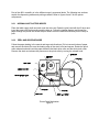
2.6.2
PEEL-AND-DISPENSE MODE
Follow the paper loading in the normal and tag mode directions. Pull out several inches of paper
and remove the labels. Be sure the leading edge of the stock is flat and square. Rotate the pinch
roller release knob and insert the paper between the black drive roller and the white pinch roller.
Remove the slack and release the pressure on the pinch roller by turning the release knob.
Printer Feed Mechanism
Figure 5
10
2.7
CLEANING INSTRUCTIONS
The Microcom 465 printer and printhead should be cleaned approximately every 5,000 labels or
every two weeks whichever occurs first. The printer should also be cleaned whenever you run out
of label stock. Proper cleaning assures that any adhesive that may come off the end of the
previous roll, is removed. A Microcom cleaning kit (part #040005) should be used for cleaning and
maintaining a Microcom printer product. It is important to note that optimum printhead life is
achieved by cleaning the printer and printhead.
To clean your Microcom 465 printer:
1)
Turn the printer off.
2)
Lift the printhead using the lift lever at the rear of the printer and remove any label stock
that remains inside the head mechanism.
3)
Using the cleaning brush, sweep away all small label and adhesive particles that may be in
the area of the printhead.
4)
Moisten a cleaning swab with the cleaning solution and wipe away any adhesive from the
rollers or the aluminum peel bar.
5)
Dampen a swab with cleaning solution and lift the print head. Take the moistened swab and
gently wipe the underside of the printhead. Repeat if necessary (if swab is extremely dirty).
6)
Moisten the felt side of a cleaning card with the cleaning solution. Raise the print head and
insert the cleaning card under print head with the felt side facing up. Lower the print head
and press the feed key to feed the card through the printer. Allow the printhead to ride on
the cleaning card. Repeat the process if needed. The cleaning card may be used once at
each end.
WARNING: DO NOT TOUCH THE PRINTHEAD WITH ANY METAL OR SHARP OBJECTS
11
12
CHAPTER 3: COMMUNICATIONS
The 465 is very versatile. It can be interfaced to PC's, mini-computers, main frames, and special
purpose machines. It is capable of serial RS-232-C and optionally Centronics® parallel
communication. The following sections explain the communication interfaces.
Out of the box, unless otherwise requested, the Microcom 465 communicates using serial RS-232C at 9600 baud, 8 data bits, 1 stop bit and no parity with both hardware and software handshaking.
This configuration may be changed as shown in Appendix E.
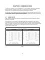
3.1
CABLE PINOUT
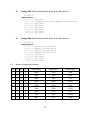
Table 1 shows the signals of the 465's 25-pin RS-232 serial port and table 2 shows the optional
parallel port configuration.
If serial RS-232-C communication is selected and XON/XOFF hand shaking is used, the only
signals the 465 requires are the RXD, TXD, and GND signals. If hardware (CTS) hand shaking is
used, a CTS signal is provided and an RTS signal is required. XON/XOFF may be disabled through
software dip switch #1 (see chapter 5). The other signals are offered in the event the host
computer requires these signals.
Serial Port Configuration
25 TO 9 PIN
25 TO 25 PIN
State 465
XX
3
XX
2
HI
20
LO
7
HI
6-8
DC
4
XX
5
HI
18
State 465
Direction
PC
HI
8 DCD---->---- DCD 1
XX
3 TXD---->---- RXD 2
XX
2 RXD----<---- TXD 3
HI
20 DTR---->---- DSR 4
LO
7 GND---<->--- GND 5
HI
6 DSR---->---- DTR 6
DC
4 RTS----<---- CTS 7
XX
5 CTS---->---- RTS 8
HI
18
5V
DB-25
DE-9
Direction
TXD---->---RXD----<---DTR---->---GND---<->--DSR---->---RTS----<---CTS---->---+5V---->----
DB-25
RXD
TXD
DSR
GND
DTR
CTS
RTS
+5V
DB-25
DC = Do Not Care
XX = Indeterminate
DC = Do Not Care
XX = Indeterminate
Table 1
13
PC
3
2
6-8
7
20
4
5
18
Parallel Port Configuration
1
2
3
4
5
6
7
8
9
10
11
=
=
=
=
=
=
=
=
=
=
=
/STROBE
D0
D1
D2
D3
D4
D5
D6
D7
/ACK
BUSY
12
13
14
15
16
17-18
19-30
31
32
33
34-36
=
=
=
=
=
=
=
=
=
=
=
PAPER OUT
SCLT
NC
NC
LOGIC GND
NC
LOGIC GND
/INIT
/ERROR
LOGIC GND
NC
(36 PIN CENTRONICS®)
Table 2
3.2
PRINTER CABLES
For parallel connection:
Use a 36 pin male centronics® to 25 pin male cable, connected from
the desired parallel port of the host computer to the 36 pin connector
on the 465.
For serial connection: If your host computer has a...
25 pin male serial port-
Use a 25 pin female to 25 pin male extension (straight) cable. (pin
#1 to pin #1...)
9 pin male serial port- Use a standard 25 pin male to 9 pin female serial cable.
Note: NULL modem cable adapters are not necessary since the printer is DCE equipment.
14
CHAPTER 4: DESIGNING LABELS USING LDS
Label Design Software (LDS) refers to the software resident in the printer used to decipher label
formats sent by the host computer. All fonts, character sets and barcodes symbologies are resident
in the printer.
A label format is produced by a series of 5 steps:
1: Control commands to define printer operation
2: A header to define label height, width, print speed, etc..
3: Field data to define placement of text, barcode, graphic or line
4: Actual text data to place in the above text or barcode fields
5: Control commands to initiate printing
4.1
CONTROL CHARACTERS
Throughout this manual there are references to control characters. In order to print them in this
manual, they have been written using standard characters and icons. Escape characters are
represented by <ESC> and a carriage return is represented by the 5 symbol. It is important to note
that all printer functions, unless otherwise noted, must be followed with a carriage return5.
4.2
GETTING STARTED
There are many different machines that can send information to the 465 printer: For example main frames, mini-computers, special purpose computers and PC's. However, if you are using the
printer for the first time, the easiest way to start is with a PC and a terminal emulation software
program. This will allow two-way, serial communication with the printer. You will be able to quickly
upload files and access label-sizing and other features that will help considerably in formatting your
first labels.
4.2.1
PC CONNECTION (SERIAL)
Items required:
A computer with at least one unused serial communications port. (COM1,COM2...)
A serial interface cable. (See section 3.2 for cable information)
A terminal emulation program. (Procomm, Telix, Windows terminal...)
Note: This communications test assumes that you have a standard serial 465 printer.
Set the communication parameters in the PC terminal software program to 9600 baud, no parity, 8
data bits and 1 stop bit. Unless modified by the user, this is the printers' communication
configuration out of the box. Depress ^C (ASCII or control code) on the PC keyboard. If the printer
prints a label, proper PC to printer communications have been confirmed. Depress ^E to verify
printer to PC communication. You will receive a text response from the printer.
15
If a terminal program is not available, it is possible to send files to the printer using the DOS COPY
command. To do this you must first create a text file containing the information to be sent (i.e. ^C ).
You may use any text editor that does not add its own formatting characters (QEDIT, Wordstar
non-document mode, DOS 5.0 EDIT, EDLIN...).
Use the following DOS MODE command to set up the appropriate PC port.
Note: COM1 may be any available communications port on your PC.
C:>MODE COM1:9600,N,8,1,P
You must then send the file to the printer using the following DOS command.
C:>COPY FILENAME COM1
4.2.2
PC CONNECTION (PARALLEL)
Items required:
A computer with at least one unused parallel communications port. (LPT1,LPT2...)
A parallel interface cable. (See section 3.2 for cable information)
Create a text file containing the information to be sent. (^C is the print command.)
^C
You may use any text editor that does not add its own formatting characters (QEDIT, Wordstar
non-document mode, DOS 5.0 EDIT, EDLIN...). Send the file to the printer using the following DOS
command. Note: LPT1 may be any available printer port on your PC.
C:>COPY FILENAME LPT1
16
4.2.3
LEARNING LDS
You can test some of the control code functions (see section 5.1) directly through the keyboard.
Large label files, such as some of those illustrated in Appendix B, may be entered in a straight
ASCII text word editor and then up-loaded to the printer using a terminal emulation program or the
DOS copy command. (To use the DOS copy command, first use the DOS mode instruction to
configure the PC. For example, MODE COM1:9600,N,8,1,P).
There are some special features offered by the 465 printer that will aid in label design. For
example, the autosize command (^A2^D395) will provide most of the header format information
needed to define the different properties of label stock. The state of the machine is accessed
through the enquiry command (^D55 or ^E). The statistical printer information is made available
through the ^A0^D295 command.
The following sections of this chapter are designed to give an overview of a label format, define the
label header, and list the different types of field information available. Chapter 5 explains the
special functions of the control codes. Once some understanding of these basic concepts are
achieved, use the quick reference guide in Appendix D for expedient label design.
4.3
FORMATTING LABELS: AN OVERVIEW
A label format consists of a header record and field records, followed by the text data to be printed.
The records describe how the label is to be printed. The header contains information about the
label itself such as label height, width, print speed, etc. The field records refer to the data section
and contain information about positioning coordinates, the type of character generators or
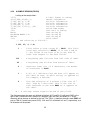
barcodes to use, etc.. Below is a sample label format. We will refer to this format as we break
down the components of its structure.
(See Figure 6)
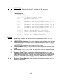
^D575
4,812,609,,205
1,100, 40, 4, 1,45
2,100, 60,17, 1,45
3,100,100, 5, 1,65
3,100,150, 5,16,2,,,,305
^D565
^D25
EASY5
MICROCOM MAKES IT5
HELLO5
^D35
A label format is coming
Header information
Field #1 information
Field #2 information
Field #3 information
Field #4 information
Select RAM Format
Text Data is Coming
Text String #1
Text String #2
Text String #3
Print Label 1
17
Microcom Label
Figure 6
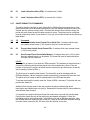
The sequence ^D575 puts the printer in format entry mode.
The next line is the header information: sizing the label (812 dots wide 609 dots high).
The next four lines are layout information for each data field in the format.
The sequence ^D565 selects the user layout.
The sequence ^D25 tells the printer to start accepting data for each defined field. (Field #1 defines
where Data #1 should be positioned.)
(Note: The label prints from bottom to top.)
The next three lines are data for each field.
Text string #3 is accessed twice. The format will print the word 'EASY' and then the barcode
equivalent.
The sequence ^D35 starts the print cycle. (Default is one copy. See section 5.3.2)
18
4.4
LABEL HEADER
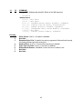
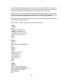
The header consist of eleven parameters. These parameters contain information about the label. It
is not necessary to enter information for all of the parameters: If a parameter is left blank, then the
default value will be used. A carriage return must follow the label header parameters.
The value of measurement for many of the header elements is the dot. There are 203 dots per inch
on a 465 print head (8 dots/mm). There is a maximum 832 dots in the X direction (width). The Y
direction (length) is 8120 dots or 40 inches long.
Most header parameters can be supplied using the autosize command. (section 5.3.3.)
Below is a list of the header element mnemonics and their default values:
HFM, LSX, LSY, WEB, GAP, DPS, LCB, AGD, SPG, OFX, OFY
0, 832, 443, 10, 10, 48,
0,
1, 535,
0,
0
19
FEED DIRECTION
OR 12 DOTS
THIS IS THE WEB VALUE
MICROCOM
Y BEGINNING
THIS IS 0,0
.125
OR 25 DOTS
THIS IS THE GAP VALUE
Label Header Parameters of a 4" X 3" Label
Figure 7
20
Refer to Figure 7 for a visual representation of the physically locatable header parameters.
The following is a description of each header element:
HFM
NUMBER OF FIELDS IN LAYOUT
This parameter is used to specify the number of fields in the layout. If more fields are
defined than what is specified for HFM, the extras will be ignored. To prevent software
confusion, do not set the HFM parameter to a number higher than the number of fields
defined.
LSX
LABEL SIZE X DIRECTION
Specifies the width of the label in dots. For example: A 3" wide label would have an LSX of
3 x 203 = 609 dots. (203 dots = 1 inch)
LSY
LABEL SIZE Y DIRECTION
Specifies the height of the label in dots. (maximum of 8120 dots)
WEB WEB SIZE
The width, measured in dots, of the webbing that is found on the left side of the label.
GAP
GAP SIZE
The height, measured in dots, of the gap between labels. Autosizing (See section 5.3.3) will
define this value.
DPS
PRINT SPEED
The speed the printer prints a label. Generally, better print quality is obtained at lower print
speeds.
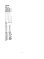
The labels per minute a particular format will print can be calculated by the equation below:
IPS x 60 seconds
Labels per Minute = --------------------------Label Height
The printer's default print speed is 3.2 inches per second (DPS value = 48). To speed it up
or slow it down, the following DPS parameters can be inserted into the label header. Note
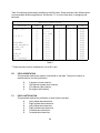
that a higher value slows the printer down and a smaller value speeds it up.
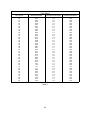
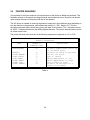
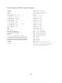
See Table 3 for a list of print speeds, DPS values, and inches per second.
21
Print Speed
DPS VALUE
MM PER SECOND
INCHES PER SECOND
INCHES PER MINUTE
20
21
22
23
24
25
26
27
28
29
30
31
32
33
34
35
36
37
38
39
40
41
42
43
44
45
46
47
48
49
50
51
52
53
54
55
56
57
58
59
60
152.4
149.9
147.3
144.8
142.2
139.7
137.2
134.6
132.1
129.5
127.0
124.5
121.9
119.4
116.8
114.3
111.8
109.2
106.7
104.1
101.6
99.1
96.5
94.0
91.4
88.9
86.4
83.8
81.3
78.7
76.2
73.7
71.7
68.6
66.0
63.5
61.0
58.4
55.9
53.3
50.8
6.0
5.9
5.8
5.7
5.6
5.5
5.4
5.3
5.2
5.1
5.0
4.9
4.8
4.7
4.6
4.5
4.4
4.3
4.2
4.1
4.0
3.9
3.8
3.7
3.6
3.5
3.4
3.3
3.2
3.1
3.0
2.9
2.8
2.7
2.6
2.5
2.4
2.3
2.2
2.1
2.0
360
354
348
342
336
330
324
318
312
306
300
294
288
282
276
270
264
258
252
246
240
234
228
222
216
204
204
198
192
186
180
174
168
162
156
150
144
138
132
126
120
Table 3
22
LCB
LABEL CONTROL BYTE
This parameter selects between the various gap detection methods.
Continuous Stock: If set to a value of 2, the printer will not activate the gap detector circuit.
After all fields are printed, the printer will advance the extra distance in the SPG header
element.
Normal Stock (leading edge): If set to a value of 0, the printer will detect the leading edge of
the label (the start of the next label).
Black Line Stock: If set to a value of 1, the printer will detect the leading edge of a black
line.
Blow Hole Stock (Slot-Cut): If set to a value of 0, the printer will detect the leading edge of a
blow hole (see software dip switch #4 (^D24) for blow hole stock).
AGD
NUMBER OF STEPS TO ACTIVATE GAP DETECTOR
This parameter selects the number of steps (dots) that the printer should skip before gap
sensing is activated. This value is usually defaulted. It is not defaulted when using stock
that contains pre-print or gaps that may cause the gap detector to trigger incorrectly.
SPG
NUMBER OF STEPS PAST GAP
The number of steps to advance the label after detection of a label gap. Use autosizing
(See section 5.3.3) to quickly evaluate this parameter for small stock.
It may also be necessary to adjust this value if using material with a sense position not
located at the end of the stock.
OFX
X DIRECTION OFFSET
This parameter moves all the fields in the X direction without changing the fields
themselves.
OFY
Y DIRECTION OFFSET
This parameter moves all the fields in the Y direction without changing the fields
themselves.
23
4.4.1
A SAMPLE SESSION (HEADER)
This is the label header from the sample label in section 4.3.
4,812,609,,20,48,,,5
5
5
4
-
4 fields following the header
812
-
Label width (LSX) of 812 (812/203 = 4 inches).
609
-
Label length (LSY) of 406 (609/203 = 3 inches).
-
The WEB parameter can be defaulted.
20
-
A GAP between labels of 20
48
-
Label print speed (DPS) of 48 = 3.2 inches per
second (from Table 3)
-
No entry for the LCB parameter means default value
of 0, normal stock on backing paper.
-
The AGD could be defaulted. This value was
confirmed using the autosize command.
-
SPG could be defaulted. This value was confirmed
using the auto-size function.
-
(20/203 = 0.10 inch).
A carriage return must follow the label header. There
were two parameters left that were not entered into the
header - OFX and OFY. Because they were not entered,
the printer assumes the default values, 0 in their
cases. Likewise, since the AGD and SPG were defaulted,
the carriage return could have followed the DPS.
Note: Defaulted fields must be separated by commas.
24
4.5
LABEL FIELDS
A field is broken down into many different parameters. These parameters contain the
information necessary to position data (text, barcodes, graphics, etc.) on the label. It is not
necessary to enter values for all of the field parameters; the default values will be used if
left blank. The fields to be defaulted must be separated by commas. A carriage return must
follow each label field.
4.5.1
BIT MAPPED TEXT AND BARCODE FIELDS
The following is a list of bit mapped (ROM stored and SOFT) field element mnemonics and
their default values:
TSN, XB, YB, CC,TCI,CGN, FO, FJ, CMX,CMY, CS, TSP
1, 0, 0, *, 1, **, 0, 0,
1, 1, *,
1
*
**
The default depends on the character generator (CGN) used.
The default depends on the TCI used.
Note: All values must be positive integers.
TSN
TEXT STRING NUMBER
Determines from which text string the field obtains the data. This allows for more than one
field to use the same text string. A TSN of 0 accesses the clock chip text string (see section
8.3). A TSN of 1 accesses the first line of data. A TSN of 2 accesses the second line of
data, and so forth. Data is the text that follows a ^D25 command in a label layout.
XB
X BEGINNING COORDINATE
The X coordinate of the field is measured in dots. The far left edge of the label as viewed
from the front of the printer is X coordinate 1. There is no X coordinate 0. The X coordinate
increases in size from left to right (See Figure 7). An XB of 203 would place the text one
inch from the left side of the label.
YB
Y BEGINNING COORDINATE
The Y coordinate of the field is measured in dots. A YB of 1 would be specified as the first
edge of the label coming out of the front of the printer during a label print. The Y coordinate
increases in size from the bottom to the top of the label (See Figure 7). A YB of 203 would
place text one inch from the bottom of the label.
25
CC
CHARACTER COUNT
This parameter determines the number of characters that will be used in a field. If the
number of characters in the selected text string is more than the quantity specified by CC,
then the remainder of the text string is ignored. If the text string has less than the number of
characters specified by this parameter, then only those characters defined by the text string
are printed. For example, the text string - MICROCOM - would be 8 characters long.
TCI
TEXT CONVERSION IDENTIFIER
This parameter determines what form the text string will be printed in. The following values
define which text conversion method is used:
1
2
3
8
11
12
13
14
15
16
*17
20
21
*22
*23
24
25
26
*28
*29
*32
*33
36
40
41
42
43
44
Text (ASCII)
Text Surrounded by Asterisks (Code 3 of 9)
Text with UPC-A/UPC-E Checksum Digit Printed
Non-Volatile Soft Fonts
Volatile Soft Fonts
UPC-A Barcode
UPC-E Barcode (SEND 11 DIGITS)
UPC-E Barcode (SEND 7 DIGITS)
Interleaved 2 of 5 Barcode
Code 3 of 9 Barcode
Text with UPC-E Checksum and Extended Bars Added
EAN-13 Barcode
EAN-8 Barcode
Text with EAN-13 Checksum and Extended Bars Added
Text with EAN-8 Checksum and Extended Bars Added
MSI 1 (Plessey)
MSI 2 (Plessey)
MSI 3 (Plessey)
Text with MSI Checksum Added - Type 1
Text with MSI Checksum Added - Type 2
Text with UPC-A Checksum and Extended Bars Added
Text with UPC-A With Extended Bars Added
Postnet
Code 128 barcode (Automatic Compression)
Code 128 barcode (No Compression)
Codabar barcode
Code 93 barcode
AS-10 barcode
* Refer to Section 7.1.1 on how to use these TCI's.
Example: For the string - 1234567
A TCI of 1 would print ASCII text.
A TCI of 42 would print a Codabar barcode.
26
CGN
CHARACTER GENERATOR NUMBER
This refers to the character generator (font size, barcode size, etc.) that is used.
The generator numbers and the specifications for the various fonts, barcodes, and graphics
are shown below. Remember, there are 203 dots per inch.
Key For Tables:
CGN
FO
Height
Width
Spacing
Font Type
'-'
-
Character Generator Number
Field Orientation
Y Direction, in Dots
X Direction, in Dots
Default Spacing Between Characters, in Dots
Font Descriptor
Use Default
Bitmapped Font Descriptions
CGN
Height
Decender
Width
Spacing
Font Type
1
2
3
4
5
6
7
8
9
10
11
12
13
14
15
5
7
7
9
9
12
16
15
18
19
19
27
27
38
38
9
12
15
20
25
25
35
35
30
30
3
5
7
5
7
9
10
12
10
15
15
21
21
50
50
1
1
1
1
2
2
2
2
2
3
3
3
3
3
4
Standard
Lower Case
Bold
Standard
Lower Case
Lower Case
OCR-A
Lower Case
Standard
Lower Case
Lower/Bold
Lower Case
Lower/Thin
Lower/Fancy
Lower/Bold
Table 4
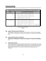
27
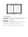
Table 5 constitutes the barcodes available on the 465 printer. Some barcodes offer different ratios
to accommodate different applications. See Section 7.1 for more information on designing with
barcodes.
Barcode Symbologies
Barcode
Code 3 of 9
I 2 of 5
*UPC/EAN
*UPC Readable
*Code 128
Codabar
Code 93
AS-10
MSI (Plessy)
CGN
Ratio
Height
Spacing
FO
2
3
4
2
3
5
2
3
-
2:1
3:1
3:1 wide
2:1
3:1
5:2
40%
40%
40%
2:1
3:1
2:1
2:1
1:1
1
1
1
1
1
1
1
1
1
1
1
1
1
1
-
0123
0123
0123
0123
0123
0123
0123
0123
0123
0123
0123
0123
0123
0123
Table 5
* These barcodes must be multiplied by 2 for a 80% ratio.
FO
FIELD ORIENTATION
This parameter defines the rotation of each field on the label. The point of rotation is
determined from the field justification.
0
1
2
3
FJ
0 degrees (normal rotation).
180 degrees (upside-down rotation).
270 degrees (right rotation).
90 degrees (left rotation).
FIELD JUSTIFICATION
This parameter defines the justification of each field on the label.
0
1
2
3
4
5
Left justified above base-line.
Right justified above base-line.
Left justified below base-line.
Right justified below base-line.
Centered above base-line.
Centered below base-line.
28
Starting position definitions:
Table 6 shows how to obtain proper character placement relative to orientations and justifications.
Character Starting Positions Relative to Field Orientations and Field Justifications
Rotation
Field Orientation and Justification
0,180 Degrees
0
1
2
3
4
5
-
Left justified above base-line
Right justified above base-line
Left justified below base-line
Right justified below base-line
Centered above base-line
Centered below base-line
90,270 Degrees
0
1
2
3
4
5
-
Left justified above base-line
Right justified above base-line
Left justified below base-line
Right justified below base-line
Centered on Y axis, right of X coordinate
Centered on Y axis, left of X coordinate
Character Starting Positions
Table 6
CMX
CHARACTER MULTIPLIER X DIRECTION
This parameter multiplies each character in the X direction. A 5 high by 3 wide character
with a CMX of 2 would produce a 5 high by 6 wide character. The maximum multiplication
is 8X.
CMY
CHARACTER MULTIPLIER Y DIRECTION
This parameter multiplies each character in the Y direction. A 5 high by 3 wide character
with a CMY of 2 would produce a 10 high by 3 wide character. The maximum multiplication
is 8Y.
CS
CHARACTER SPACING
This parameter adjusts the spacing between each character. If this parameter is not used,
then the default for the selected character generator (CGN) is used. Barcodes have default
spacing according to the indicated multiplier. Multiplying a text string will not multiply the
spacing between characters. This element should be used to properly space the
characters.
29
TSP
TEXT STARTING POSITION
This parameter marks the starting position of the character in the text string to be used as
data. This is useful for allowing several fields to use sections of the same text string,
minimizing the amount of data transmitted. For example, for the text string 0123456789, A
TSP of 5 and a CC (character count) of 2 would print 45. See section 5.3.4 for use of this
parameter with clock fields.
30
4.5.2
GRAPHIC IMAGE FIELDS
A graphic field is broken down into ten different parameters. The first position must be set
to 1. The next two are the start coordinates. The next two positions should be set to 1,7.
The GN position refers to the slot number where the desired image is stored. GO and GJ
change the print orientation and justification. The GMX and GMY positions are used to
magnify the image. A carriage return must follow every graphic field definition line.
If printed areas overlap, the common areas will become white.
The following is a list of graphic image field mnemonics and their default values:
*, XB, YB,
1, 1, 1,
*
*,
1,
*, GN, GO, GJ, GMX,GMY
7, 1, 0, 0,
1, 1
These values remain constant and must be entered to produce a valid
image.
Note: All values must be positive integers.
XB
X BEGINNING COORDINATE
The X coordinate of the field is measured in dots. The far left edge of the label as viewed
from the front of the printer is X coordinate 1. There is no X coordinate 0. The X coordinate
increases in size from left to right (see Figure 7). An XB of 203 would place the image one
inch from the left side of the label.
YB
Y BEGINNING COORDINATE
The Y coordinate of the field is measured in dots. A YB of one would be specified as the
first edge of the label coming out of the front of the printer during a label print. The Y
coordinate increases in size from the bottom to the top of the label (see Figure 7). A YB of
203 would place the image one inch from the bottom of the label.
GN
GRAPHIC NUMBER
This refers to the graphics location in printer memory. Valid slots are 1-8.
GO
GRAPHIC ORIENTATION
This parameter defines the rotation of the graphic image on the label. The point of rotation
is determined from the graphic justification.
0
1
2
3
0 degrees (normal rotation).
180 degrees (upside-down rotation).
270 degrees (right rotation).
90 degrees (left rotation).
31
GJ
GRAPHIC JUSTIFICATION
This parameter defines the justification of the graphic image on the label.
0
1
2
3
4
5
Right justified above base-line.
Left justified above base-line.
Right justified below base-line.
Left justified below base-line.
Centered above base-line.
Centered below base-line.
GMX GRAPHIC MULTIPLIER X DIRECTION
This parameter multiplies the graphic image in the X direction. The maximum multiplication
is 8X.
GMY GRAPHIC MULTIPLIER Y DIRECTION
This parameter multiplies the graphic image in the Y direction. The maximum multiplication
is 8Y.
32
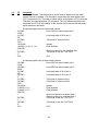
4.5.3
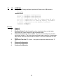
LINES/RECTANGLES
A line field is broken down into ten different parameters. The first position must be set to 1.
The next two are the start coordinates. The next five positions should be set to 1,5,1,0,0.
The XS and YS positions determine the width and height of the line. A carriage return must
follow every line definition.
If printed areas overlap, the common areas will become white.
The following is a list of graphic image field mnemonics and their default values:
*, XB, YB,
1, 1, 1,
*
*,
1,
*,
5,
*,
1,
*,
0,
*, XS, YS
0, 1, 1
These values remain constant and must be entered to produce a valid line.
Note: All values must be positive integers.
XB
X BEGINNING COORDINATE
The X coordinate of the field is measured in dots. The far left edge of the label as viewed
from the front of the printer is X coordinate 1. There is no X coordinate 0. The X coordinate
increases in size from left to right (see Figure 7). An XB of 203 would place the text one
inch from the left side of the label.
YB
Y BEGINNING COORDINATE
The Y coordinate of the field is measured in dots. A YB of one would be specified as the
first edge of the label coming out of the front of the printer during a label print. The Y
coordinate increases in size from the bottom to the top of the label (see Figure 7). A YB of
203 would place text one inch from the bottom of the label.
XS
X SIZE
The X size of the line is measured in dots.
YS
Y SIZE
The Y size of the line is measured in dots.
33
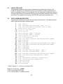
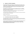
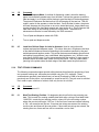
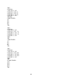
MAKING LINES
Program sample: Lines
^D57<CR>
7,506,771,,,30<CR>
1,240,005,1,5,1,0,0,004,255<CR>
1,240,260,1,5,1,0,0,004,255<CR>
1,400,005,1,5,1,0,0,004,255<CR>
1,400,260,1,5,1,0,0,004,255<CR>
1,244,040,1,5,1,0,0,156,004<CR>
1,404,040,1,5,1,0,0,100,004<CR>
1,055,300,1,5,1,0,0,185,004<CR>
^D56<CR>
^D2<CR>
^D3<CR>
Lines
Figure 8
34
4.5.4
A SAMPLE SESSION (FIELDS)
Looking at the sample label...
^D575
A label format is coming
4,812,609,,20,48,,,5
Header Information
1,100, 40, 4, 1,45
Field #1 information
2,100, 60,17, 1,45
Field #2 information
3,100,100, 5, 1,65
Field #3 information
3,100,150, 5,16,2,,,,305
Field #4 information
^D565
Select RAM Format
^D25
Text Data is Coming
EASY5
Text String #1
MICROCOM MAKES IT5
Text String #2
HELLO5
Text String #3
^D35
Print Label
... and referring to Field #1.
1,100, 40, 4, 1,45
5
1
-
Field refers to text string #1 - EASY. This field
could have referred to HELLO, if it had a TSN of
3. The fields do not have to be in any kind of
order with respect to the data fields.
100
-
X beginning (XB) 100 dots from left side of label.
40
-
Y beginning (YB) 40 dots from bottom of label.
4
-
Character Count (CC) of 4 characters, the amount
of characters in EASY.
1
-
A TCI of 1 indicates that the data will appear on
the label as text, an ASCII string, as opposed to,
for example, a barcode.
4
-
This CGN selection of 4 selects a font size of 7
dots high by 5 dots wide. This is the size of
each character in the word EASY as it appears on
the label.
5 -
A carriage return signals the end of this field.
The field parameters that were not defined will default. A FO and FJ of 0 will place EASY to the
right of the X coordinate with a rotation of 0 degrees. CMX and CMY will default to 1, so the
character will be the size as defined by the font. The TSN is 1, therefore the entire word EASY will
print (a TSN of 2 would have printed ASY). CLX and CLY will default to 5 and 7, respectively, so a
full character will be printed.
35
36
CHAPTER 5: PRINTER COMMANDS
The 465 printer has a large and versatile collection of command codes to meet the special needs
of labeling applications. Most of the commands use a ^D control sequence, however the printer
also recognizes a selected number of other control sequences.
For all the commands listed in this manual, the 465 will recognize either the one-character control
character or the two-character caret and alpha character sequence. In other words, for a PC
keyboard, the same command can be generated either by holding down the control key and
pressing the letter or by entering two characters -the ^ (a caret, the character generated if you
press the Shift key and the 6) and an alpha character (upper or lower case).
To protect against errors, in situations where two-character caret-alpha sequences are used
exclusively as printer commands, control character recognition can be disabled. This is done
either through software dip switch #1 position 3 (^D21) or command ^A1^D935.
Some main-frame and mini-computers cannot use the ASCII '^' character. In these cases
substitute the ASCII pipe symbol '|' or use the one character control-code representation.
The caret symbol can be used in text or barcodes by preceding it with another caret.
37
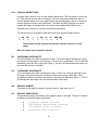
5.1
SPECIAL PRINTER CONTROL CODES
The following control characters perform special functions. All other control characters are
ignored. Some of these instructions are also accessible through a ^D sequence.
^A
Accumulator Mode: Used to supply parameters for ^D commands. These parameters
must be positive integers and are generally decimal numbers but they can be binary if
preceded by a ASCII B. (i.e., ^AB00000001^D215 equals ^A1^D215)
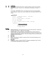
^B
Text Entry Mode: Instructs the printer to enter text entry mode. This command (or ^D25)
must be sent before the text information. This command is equivalent to ^D25 but does not
require a 5 after it (ie. ^Btext data string5). Because control B is shorter than ^D25, it is
easier to use in direct terminal mode. In general it is better to use ^D25 inside a file or
program.
^C
Print a label: Prints a single label or starts printing a batch of labels. This command is
equivalent to ^D35 but does not require a 5 after it. Because Control C is shorter than
^D35, it is easier to use in direct terminal mode. In general it is better to use ^D35 inside a
file or program.
^D
Command Mode: Used to issue commands to the printer. This command is normally
preceded by a ^A sequence (see above).
^E
Printer Enquiry: See section 5.2 for more details (equivalent to ^D55 but does not require
a 5 after it). Because Control E is shorter than ^D35, it is easier to use in direct terminal
mode. In general, it is better to use ^D55 inside a file or program.
^M
Terminate Text or Data String: Must be used to terminate a text or data string. (Same as
a carriage return or enter key on computer keyboard)
^H
Deletes The Last Printable Character Entered: This is used only when communicating
to the printer through the keyboard. (Same as Delete key on computer keyboard.)
^K
Print Test Label: A test label consists of a series of diagonal lines. It is useful in
determining the condition of the dots on the printhead (equivalent to ^D115).
^L
Print Blank Label: (Equivalent to ^D125)
^Q
XON: Instructs the printer to continue sending data.
^S
XOFF: Instructs the printer to stop sending data.
38
5.2
PRINTER ENQUIRIES
It is important for the host computer to know the status of the printer as labels are produced. This
facilitates security in the system and flags electrical and mechanical errors. Enquiries can also be
used to adjust the pace of the printer with that of the operator.
The 465 printer is capable of returning responses to enquiries in three different ways depending on
how the machine is programmed. (see software dip switch1 #1, ^D21, Section 5.3.) The text
equivalent response returns a text string, giving the state of the machine. The ^ equivalent returns
an ASCII '^' response followed by the defining alpha character. The control code equivalent returns
an actual control code.
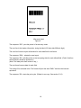
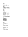
The printer will send to the host one of the following responses in response to a ^E or ^D55:
Enquiry Responses
TEXT
^ALPHA or
CONTROL CODE
DEFINITION
>RESTARTED<
^Z
>READY<
>DATA ERROR<
>LOW STOCK<
>LOW TEMP<
>OVER TEMP<
>OVER VDD<
>TAKE LABEL<
^F
^U
^Y
^^
^[
^\
^V
Printer experiences power up
or software reset
Printer is ready to process
Serial I/O error
Out of labels
Head temperature is low
Head temperature is high
VDD voltage is high
Printer is waiting for a
label to be taken
Table 8
39
5.3
SENDING ^D PRINTER COMMANDS
Unless otherwise specified, these commands are entered by sending a ^DXX, where XX is the
command number. It is followed by a carriage return or another control code. Some commands
load data or control numbers and are preceded by a ^AXX, where XX represents the data or
control number. Unless otherwise specified, command codes should appear first in the label
format, if a label format is being sent.
Unless stored in a non-volatile saved format file, all commands not listed in 5.3.1 (the Battery
Backed RAM and software switch section) are not retained when the printer is turned off and, if
desired, must be sent again upon power-up.
When possible, the following commands are grouped by function. See the Quick Reference
Command Summary in Appendix D for a listing by number.
Some commands can be substituted with equivalent control codes. If this is the case, there will be
an equivalence statement in the description.
Example of command usage:
^A3^D75^D35 (This sequence will print a batch of three labels).
5.3.1
SOFTWARE SWITCHES/BATTERY BACKED COMMANDS
The following commands are different from the other printer commands in that they are stored in
Battery Backed RAM, are non-volatile and configure the machine upon power-up. Once sent to the
printer, they do not need to be sent again.
Verify the new dip switch settings by either sending ^D29 to the printer (switch settings will be sent
back to the computer) or place the printer in 'test mode' by turning on the printer with the
PRINT/PAUSE button pressed (this will print a label with switch statistics). Note: Turn the
printer off and back on to clear this test mode.
40
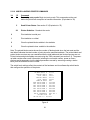
^A
^D
21
COMMAND
Change SW1: Software dip switch #1. The dip switches are the only commands
that use binary input. They can use a ^AB sequence followed by an 8 digit 0 or 1
code.
For example: ^AB10000011^D215 will configure the printer for a text equivalent
enquiry response, accept control codes, disable echo, and enable XON/XOFF flow
control.
12345678
^ABxxxxxxxx
*******. 1=XON/XOFF Enable, 0=Disable
******.) Not Used
*****.)) 1=Echo Enable, 0=Disable
****.))) Not Used
***.)))) Not Used
**.))))) 1=Ignore Control Codes, 0=Accept
*.)))))))),
.)))))))),*Enquiry Response
00=Control Codes
10=Text Equivalent
11=^Equivalent
Position:
1,2
3
4
5
6
7
8
Enquiry Response: This determines what the printer will send back in response to
an enquiry. See chapter 5, table 8 for more details.
Control Codes: It is not acceptable in some applications to allow the printer to
accept control codes (ASCII characters below 20 hex), because of the way the host
computer interacts with the machine. This switch setting will allow or disallow printer
response to control code use.
Not Used
Not Used
Echo: If this feature is enabled, the printer will echo all received characters to the
communications port.
Not Used
XON/XOFF: Enable or disable XON/XOFF software handshaking. Clear To Send
(CTS) hardware handshaking is always enabled.
41
^A
^D
22
COMMAND
Change SW2: Software dip switch #2. Below is the ^AB sequence:
12345678
^ABxxxxxxxx
*******.)))),
******.)))),*
*****.)))),** Power-up Label Format
*****
000=ROM Format File 1
*****
001=ROM or Non-Volatile RAM Format File 1
*****
010=ROM or Non-Volatile RAM Format File 2
*****
011=ROM or Non-Volatile RAM Format File 3
*****
100=ROM or Non-Volatile RAM Format File 4
*****
101=ROM or Non-Volatile RAM Format File 5
*****
110=ROM or Non-Volatile RAM Format File 6
*****
111=ROM or Non-Volatile RAM Format File 7
****.)))) 1=Use Non-Volatile RAM Format File, 0=ROM
***.))))) 1=Print Button Enable, 0=Disable
**.)))))) 1=Line Feed Button Disable, 0=Enable
*.))))))) 1=>RESTARTED< Response Enable, 0=Disable
.)))))))) 1=Clear Text Enable, 0=Disable
Position:
1
2
3
4
5
6,7,8
Clear Text: If enabled, all variable text will be erased when a ^D25 or ^B is
processed.
>RESTARTED< Response: If the printer has been reset and this switch has been
enabled, the printer will respond to the first poll by sending the >RESTARTED<
message. If additional enquiries are made, the printer will respond normally. The
>RESTARTED< response is only issued once after reset.
Line Feed Button: Set to 1, the printer will not allow keypad use, even for paper
feed.
Print Button: If this is 0, the 'PRINT' key acts like a Form Feed and printing will
occur. All other keypad functions respond normally.
Power-up Format Type: This parameter determines whether to use a user
loadable non-volatile saved format file or a factory ROM format for the power-up
label (defined by positions 6, 7, and 8). See section 5.3.6 for non-volatile saved
format file information. Please contact your service organization if changes or
additions need to be made to the ROM formats (i.e., the standard power-up label).
Power-up Format Selection: These switches decide which format to use as a
power-up label default.
42
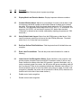
^A
^D
23
COMMAND
Change SW3: Software dip switch #3. Below is the ^AB sequence:
12345678
^ABxxxxxxxx
*******.)Not Used
******.) Not Used
*****.)) 1=Ribbon Break Sensor Disable, 0=Enable
****.))) 1=Pulse Tone On Piezo, 0=Continuous
***.)))) 1=Head Up Error Disable, 0=Enable
**.))))) 1=Response After Print Enable, 0=Disable
*.)))))) Not Used
.))))))) 1=Piezo Sound Disable, 0=Enable
Position:
1
2
3
4
5
6
7
8
Piezo Sound: If set to 1, the piezo is disabled.
Not Used
Response After Print: If enabled, an enquiry response will be sent back through
the communications port after every print.
Head Up Error: If set to 1, head up error checking is disabled.
Pulse Tone On Piezo: If set to 1, the piezo is disabled.
Ribbon Break Sensor: If disabled, no error will occur if ribbon is out.
Not Used
Not Used
43
^A
^D
24
COMMAND
Change SW4: Change software dip switch #4. Below is the ^AB sequence:
12345678
^ABxxxxxxxx
*******.)
******.))
*****.)))
****.))))
***.)))))
**.))))))
*.)))))))
.))))))))
Position:
1
2
3
4
5
6
7
8
European Configuration
European Configuration
European Configuration
1=Pass ASCII over 7F, 0=Less than 80 only
1=Auto-size on Power-up Enable, 0=Disable
1=Blow-hole Stock Enable, 0=Disable
Always 0
Always 0
Always 0
Always 0
Blow-hole Stock: Enable this position when using blow-hole or cut-slot stock:
Stock that uses a hole instead of a gap to separate labels.
Auto-size on power-up: When enabled, the printer automatically sizes the label
stock when turned on. The printer then uses these header values for all subsequent
label formats. See the ^D39 command in section 5.3 for more information on autosizing.
Pass ASCII Text Over 7F: If set to 1, the printer will process characters over 7F
hex.
European Configuration
European Configuration
European Configuration
44
^A
^D
25
COMMAND
Change SW5: Change software dip switch #5. Below is the ^AB sequence:
12345678
^ABxxxxxxxx
*******.)
******.))
*****.)))
****.))))
***.)))))
**.))))))
*.)))))))
.))))))))
Position:
1
2
3
4
5
6
7
8
Not Used
1=Enable Auto Error Message Transmission
Not Used
Not Used
Not Used
Not Used
Not Used
Not Used
Not Used
Not Used
Not Used
Not Used
Not Used
Not Used
Auto Error Message Transmission: When set to 1, all catastrophic error
messages will automatically be sent to the serial port. (see Table 8)
Not Used
45
^A
^D
26
COMMAND
Change SW6: Change software dip switch #6. Below is the ^AB sequence:
12345678
^ABxxxxxxxx
*******.)
******.))
*****.)))
****.))))
***.)))))
**.))))))
*.)))))))
.))))))))
Position:
1
2
3
4
Not Used
Not Used
Not Used
Not Used
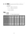
5-8
Memory Configuration
Memory Configuration
Memory Configuration
Memory Configuration
Not Used
Not Used
Not Used
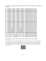
Not Used
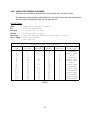
Memory Configuration Switches
#5
#6
#7
#8
User Memory
Max Slices
Label Height
0
0
0
0
296K
1651
8.25"
1
0
0
0
264K
1966
9.825"
0
1
0
0
232K
2281
11.4"
1
1
0
0
200K
2596
12.975"
0
0
1
0
168K
2911
14.55"
1
0
1
0
136K
3226
16.125"
0
1
1
0
104K
3541
17.7"
1
1
1
0
72K
3856
19.275"
0
0
0
1
40K
4171
20.85"
46
^A
XX
^D
36
Command
Adjust Contrast Base: Use this command to adjust/calibrate the default contrast.
Since the non-permanent ^D35 command is used to control the darkness in a
format file, the ^D36 command is offered to correct any contrast differences that
may exist between different printers while using the same format file. This
command is non-volatile and only needs to be sent once. Do not include this
command inside a format file as it will also change the base print contrast of every
other format printed. Use the ^D35 command to make temporary adjustments inside
a format file. This command has a range of 10 to 200 in increments of 1.
5.3.2
PRINTING COMMANDS
The following commands initiate label printing or define the number of labels to be printed.
^A
^D
3
Command
Print Command: Prints a single label or starts the printing of a batch of labels.
This is usually the last command in a format file. (Equivalent to ^C)
11
Print a Test Label: Prints a label with diagonal lines that is useful in determining
the condition of wear of the print head. (Equivalent to ^K)
12
Print a Blank Label: (Equivalent to ^L)
XX
73
Load copies count: Tells the printer to print a group of labels. Will not increment
serial numbers (use a ^D75). This can, however, be used in conjunction with ^D75
(load label count) to allow duplicate labels to be made inside a batch. For example,
to make a batch of three serial number labels before incrementing the serial
number. The batch of labels will be printed when a ^D3 is executed. Therefore, this
must precede a ^D3 command. Example usage: ^A20^D73^D35 - Prints 20
identical labels.
1
74
Infinity Print: Prints a batch of labels but will continue to print until the printer is
turned off or paused. This command is most useful in tag/tear or peel-and-dispense
modes. ^A1 activates this mode. Can be used with serial numbers. Example
usage: ^A1^D74^D35 - prints until printer is turned off or paused.
47
^A
XX
^D
75
COMMAND
Load Label Count: Tells the printer to print a batch of labels using the serial
number function if enabled. Can be used in conjunction with load copies count
(^D73). The batch of labels will be printed when a ^D35 is executed. Therefore, this
must precede a ^D3 command. The only difference between this command and
^D73 is in the ability of this command to increment and decrement sequential
numbers in the batch. (see Section 5.3) Example usage: ^A20^D74^D35 - Prints 20
serial number labels.
XX
76
Load Delay Time Between Printed Labels: Delays the printing between labels in
a batch. Preceded by ^A which contains the wait in 1/10ths of a second increments.
The maximum value is 650. Example usage: ^A10^D765 - introduces a one
second delay between printed labels.
5.3.3
AUTOSIZING AND VALID GAP COMMANDS
The autosize feature gives important format file values for the label header. These values
are:
LSY - Label height
GAP - Distance between labels
AGD - Steps until activating gap detector
SPG - Steps past gap
^D91 Value - States transmissive properties of stock to
the gap detector. See ^D91 definition later
in this section. This value is obtained from
auto-sizing and should be inserted as the ^A
value associated with the ^D91 command. This
must be done whenever stock is changed.
When autosize is executed, a sample of approximately 10 labels will run through the
printer. The printer averages the values it receives from these labels.
To autosize labels that use a black line instead of a gap, execute a ^A1^D475 to put the
printer in black line mode.
To autosize blow-hole stock, set software dip switch 4 for blow-hole stock (see Section 4.4)
and then autosize.
There is also a power-up autosize feature as defined in section 5.3, ^D24.
48
^A
^D
39
Command
Autosize Label:
0
Clears the use of autosize values set by ^A1^D395.
1
Uses the values obtained for the variables above instead of what the user supplies
in the header of the file format. This will not display the variables on the screen.
2
Automatically sizes the label and displays on the screen the values for the size
variables. These values should be placed in the label header for that stock.
3
Same as ^A2^D395, but prints the values on a label, instead of on the screen.
XX 91
Load Value for Printer to See Valid Gap. Obtained from the autosize (^D39)
command. This value states the translucent properties of stock to the gap detector.
This ^AXX^D915 command should be at the beginning of all format files if
suggested ^D91 value returned from autosize is not between 50 and 70 or the
default value creates skipping over the label gap. Skipping over the label gap is
defined as the printing of one label and then the printing of a blank label. This
condition occurs because the default ^D91 value cannot adjust for stock that has
unusual translucent properties (old stock, thick tag stock, unusual backing paper,
etc.). This problem can be easily rectified by autosizing the stock.
49
5.3.4
REAL-TIME CLOCK
^A
^D
30
Command
Change Clock: Use the sequence below to set the time and date of the optional
real-time socket:
^D305
HH:MM:SS5
DD/MM/YY/W5
HH = hours (24 hour format)
MM = minutes
SS = seconds
W
1
2
3
4
5
6
7
=
=
=
=
=
=
=
=
MM = month
DD = day of month
YY = last 2 digits of
year
day of the week
SUN
MON
TUE
WED
THR
FRI
SAT
The clock produces a string of text that is accessed through use of a TSN of 0 (See
table 9 for definitions of field parameters).
The text string is shown below...
HH:MM:SS MM/DD/YY XXX DD/MM/YY XXX
...where xxx is the day of the week.
These values should be inserted into the Field parameters for proper clock text access:
Clock Field Parameters
TSN
TSP
CC
0
1
8
HH:MM:SS
0
10
8
MM/DD/YY
0
19
3
Day of Week
0
23
8
DD/MM/YY
0
32
3
Day of Week
Table 9
50
TEXT
A sample program using the clock function:
^D575
2,,6095
0,320,40,8,16,2,,4,2,60,,105
0,320,20,8,1,10,,4,,,,105
^D565
^D35
^D575
3,,6095
0,320,40,12,16,2,,4,2,60,2,235
0,320,20,12,1,10,,4,,,,235
1,320,110,20,1,11,,45
^D565
^D25
EUROPEAN DATE FORMAT5
^D35
^D575
3,,6095
0,320,40,12,16,2,,4,2,60,2,105
0,320,20,12,1,10,,4,,,,105
1,320,110,20,1,11,,45
^D565
^D25
US DATE FORMAT5
^D35
^D575
3,,6095
0,320,20,34,1,10,,45
0,550,80,8,1,10,3,45
1,320,60,18,1,13,,45
^D565
^D35
5.3.5
SERIAL NUMBER COMMANDS
The following commands, ^D80 through ^D89, refer to the serial numbering functions of the 465
printer. The 465 can increment or decrement any single serial number by any amount.
^A
^D
80
Command
Disable all serial numbering.
51
XX
81
Disable Single Serial Number Field: Will disable an individual serial number
field.
XX
82
Enable Single Serial Number Field: Will recall a stored serial number (1-16) and
place it into an individual serial number field on the label. XX determines the stored
serial number slot to be recalled. The TSN (Text String Number) is selected by
following the ^AXX^D825 with the TSN surrounded by quotes ("TSN"5). This
command is not stored between labels, it must be sent each time a format is sent
and must be located after the ^D57 command and format information.
XX
83
Select Stored Serial Number to increment: Tells the printer which stored serial
number to increment. See section 4.5 on text string numbers. The ^A value states
which serial number is selected.
XX
84
Select Stored Serial Number to decrement: Tells the printer which stored serial
number to decrement. See section 4.5 on text string numbers. The ^A value states
which serial number is selected.
85
Clear All Stored Serial Numbers: This function will erase any serial numbers
stored in memory.
XX
86
Load New Serial Number Into Memory: This command loads a serial number
into non-volatile memory. XX is used to select the serial number slot (1-16). The
actual serial number, up to 9 characters, is placed in quotes and follows the
^AXX^D865.
XX
87
Load Increment/Decrement Value Into Memory: Will load and store a step
value into non-volatile memory. The stored serial number to be affected is chosen
with the XX variable and the actual step value, up to 9 characters, is entered by
following the ^AXX^D875 with the step value surrounded by quotes.
XX
88
Send Serial Number To Serial Port: ^A specifies which stored serial number (116) to send.
XX
89
Send Increment/Decrement Value To Serial Port: ^A specifies which stored
increment/decrement value (1-16) to send.
52
^A
XX
^D
75
Command
Load Label Count: Tells the printer to print a batch of labels using the serial
number function if enabled. Can be used in conjunction with load copies count
(^D73, see section 5.3). The batch of labels will be printed when a ^D3 is executed.
Therefore, this must precede a ^D3 command. The only difference between this
command and ^D73 is in the ability of this command to increment and decrement
serial numbers in the batch.
A sample program using a single serial number:
^A1^D865
;Load 1000 into serial number slot 1
"1000"
^A1^D875
;Load step value of 50 for slot 1
"50"
^A1^D835
;Tell printer to increment slot 1
^D575
1,812,6095
;Header
1,435,24,4,1,14,0,,1,1,35
;Field definition
^D56^D25
5
;Reserve a space for the serialized field
^A1^D825
;Tell printer to use slot 1 on TSN 1
"1"
^D35
;Print
A sample program using multiple serial numbers:
^A1^D865
;Load 1000 into serial number slot 1
"1000"
^A2^D865
;Load 2000 into serial number slot 2
"2000"
^A1^D875
;Load step value of 50 for slot 1
"50"
^A2^D875
;Load step value of 25 for slot 2
"1"
^A1^D835
;Tell printer to increment slot 1
^A2^D835
;Tell printer to increment slot 2
^D575
2,812,6095
;Header
1,100,20,4,1,115
;Field definition
2,100,40,4,1,115
;Field definition
^D56^D25
5
;Reserve a space for serialized field 1
5
;Reserve a space for serialized field 2
^A1^D825
;Tell printer to use slot 1 on TSN 1
"1"
^A2^D825
;Tell printer to use slot 2 on TSN 2
"2"
^D35
;Print
53
5.3.6
LABEL HEADER COMMANDS
The following ^D commands, 41 - 51, all refer to label header values. They are provided to
allow single element modification without having to send the entire label header. The printer
will use these values for all subsequent label formats unless a ^D40 is executed, the
machine is powered off, or a replacement value is sent or included in a new label header.
More information on what these label header values mean can be found in section 4.4.
Example usage: ^A1015^D435 - Sets the label height for all following formats to 5 inches.
^A
^D
40
Command
Clear Commands 41-51. (Returns header values to default.)
XX
41
Load number of fields in layout (HFM): ^A determines number of fields.
XX
42
Load label width in dots (LSX): ^A indicates the width.
XX
43
Load label height in dots (LSY): ^A defines the height.
XX
44
Load web size in dots (WEB): ^A specifies the web size.
XX
45
Load gap size in dots (GAP): ^A denotes the gap size.
XX
46
Load print speed (DPS): ^A designates the print speed. (See table 3 for speed
values.)
XX
47
Load label control byte number (LCB): ^A specifies the method of gap
detection.
XX
48
Load number of steps to activate gap detector (AGD): ^A determines the
number of steps.
XX
49
Load number of steps past gap (SPG): ^A designates the number of steps.
54
XX
50
Load X direction offset (OFX): ^A indicates the X offset.
XX
51
Load Y direction offset (OFY): ^A denotes the Y offset.
5.3.7
SAVED FORMAT FILE COMMANDS
The printer has the capability to store format files to RAM without processing them. Later,
these format files can be accessed repeatedly at very high speeds, because access to the
formats are now a direct memory fetch. If formats are saved in Non-Volatile memory the
printer will retain these format files after removal of power. The printer can be configured
through software dip switch 2 (see section 5.3) to use one of these formats as the power-up
label default.
^A
XX
^D
54
Command
Send Non-Volatile Saved Format File to Serial Port: ^A selects which single
non-volatile saved format (1-32) to send to the host via the serial port.
XX
58
Process Non-Volatile Saved Format File: ^A selects which user entered format
(1-32) is to be printed.
XX
59
Save Format File to Non-Volatile Memory: ^A selects which slot (1-32) in which
the user entered format is to be placed. The format file must be terminated by an
ESCape (1B hex) character.
USAGE:
To save a file in memory, first send the ^D59 command. This indicates to the printer that a
format file is following and should be placed in the first available slot. (Note: If the slot
number of the format is critical, the printer can be instructed to put the format in a specific
slot be sending ^A(slot #)^D595.)
The final step is to send the label format. The format file must be terminated with an
ESCape character (1B hex) so that the printer knows that the complete file has been sent.
The printer will not accept an ASCII representation of the ESCape character.
To access the stored file, serially send the ^A(slot #)^D585 command. The printer will now
process the stored file.
Additional files may be saved in the same manner by simply following the above
instructions and substituting a new (slot #). Remember the printer has 32 slots available to
store different label formats.
It is important to note that the saved format file mode works very well with variable data.
Configure the format file with all the positioning and header information. Follow this
information with all the fixed text data. Terminate the file with an ESCape character. Now
the variable data may serially be sent to the file. It may be the difference between sending
two lines of data versus the full 120 lines of the file! Access is very fast.
55
To read a file that has previously been sent to the printer, use the ^AX^D545 command,
where ^AX denotes the file (slot #) to be read. The printer will send the file to the serial port.
If you are using a terminal or terminal utility, the file will be sent to your screen.
Sample files: File #1 initiates the save format file memory and downloads saved format file
#1. File #1 includes all the fixed data on the label. File #2 is the file that initiates processing
of file #1 and includes all variable data for the format. File #2 also prints the label.
File #3 shows how a second saved format would look. The data and processing commands
for file #3 are contained in file #4.
NOTE: <ESC> = 1B hex, 27 decimal, or the ASCII equivalent ^[
File #1
^A1^D595
^D575
4,288,193,5,19,30,0,1,1485
1,100,20,10,1,10,0,2,1,1,,15
1,210,20,7,1,10,0,2,2,2,,115
1,152,154,12,12,,0,2,2,100,,185
1,130,54,12,32,,0,2,2,2,,185
^D565
<ESC>
File #2
^A1^D585
^D25
24 PRINTS $ 3.79 204963403795
^D35
File #3
^A2^D595
^D575
4,620,161,,18,35,,73,35
1,120,110,50,1,115
2,120, 80,70,1,105
3,120, 60,70,1,105
4,120, 40,70,1,105
^D565
<ESC>
File #4
^A2^D585
^D25
MICROCOM CORPORATION5
8333-A GREEN MEADOWS DR., N.5
WESTERVILLE, OH 430815
(614) 548-62625
^D35
56
5.3.8
LABEL PRESENCE SENSOR CONTROL
The label presence sensor instructs the printer to dispense labels at the operators pace. If a label
has been printed but not removed, the printer will wait until the label is removed before allowing
another label to be printed. The following modes define its operation.
^A
XX
^D
96
Command
Load Advance Delay: ^A specifies how many milliseconds to delay repositioning
of the label in tag/tear and peel-and-dispense modes. Example usage:
^A1000^D965 would delay label advance by one second.
97
Tag/Tear Operation: A method of dispensing a label where the label is advanced
so the perforation between labels is on the tear bar. This allows heavy tag stock
and regular label stock to be torn off easier. The distance of advancement may also
be defined by the user, if used in conjunction with the ^D95 command. There are
three modes of operation:
0
Disable tag/tear operation.
1
Advance after every label: Causes the paper to be advanced to the perforation after
every label is printed. As soon as the label is taken, the paper is backed up to the
beginning of the next label. This mode forces the printer and computer to operate at
the speed of the operator.
2
Advance after copies count: Causes the paper to be advanced to the perforation
after the number of labels specified by the copy count (^D73) or label count (^D75)
commands have been printed. As soon as the labels are taken, the paper is backed
up to the beginning of the next label.
3
Advance when idle: This causes the paper to be advanced to the perforation
whenever the printer does not have a label request pending. When another label
request is made, the paper backs up and the next label is printed.
It is possible to have more than one mode in effect at a time. For example, Modes
2 & 3 which would cause the label stock to be advanced after a copies count and
then remain advanced until another label request is made.
57
^A
^D
98
Command
Peel-and-Dispense Mode: A method of dispensing a label, where the backing
paper is automatically peeled away from the label. It allows the operator to take the
label and apply it to an object without having to peel the label off the backing paper.
The printer will advance the label so that it is still hanging off the tear bar. This will
make it easier for the operator to take the label. Once the label is taken, the printer
will back the paper into the printer so as not to waste label stock. Larger labels may
require the use of the front label support rack (see section 8.1). This will prevent the
label from falling off and sticking to the front of the printer. The distance of
advancement can also be user defined by the ^D95 command.
0
Turn off peel-and-dispense mode with ^D98.
1
Turn on peel-and dispense mode.
XX
95
Load User Defined Steps for Label to Advance: Used in conjunction with
tag/tear and peel-and-dispense mode. This value, after print, will advance the label
a user defined distance instead of defaulting to the measure specified by the peeland-dispense and tag/tear modes. This printer feature accommodates special stock
and special circumstances (very small labels, label applicator, etc.). While the user
may specify 64,000 steps, it is not recommended that the number of steps create a
situation where the entire label is back fed into the printer. This may create labels
jamming in the printer when the back edge of the label meets the print head unit.
5.3.9
TEXT STRINGS COMMANDS
The following commands support special editing features that allows the positioning of new
text, protects existing text, and enters text without using the ^D25 delimiter. These
commands are generally used when there is a format file already in RAM (a format file
previously sent to the printer, not necessarily a saved format file). They are used to edit that
file in order to print variations of a label, often only the text in one field.
^A
^D
60
Command
Clears command 61
XX
61
Mark Text Starting Position: ^A designates which text field to start entering new
data. This is useful for creating variable data fields after a string of fixed data fields.
^AXX^D615 marks the text starting position, where XX is the text string number
where the new text will begin. If XX is a 2, the first line of new text entered following
a ^D25 will overwrite text line two. If two new text strings are entered, the existing
text lines two and three will be over-written. If three new text strings are entered, the
existing lines two, three and four will be overwritten, and so forth.
58
62
Pre-padded Text: This command is sent after text that is to appear at the
beginning of each field. Text sent after this command will be appended to the prepadded text. This is useful, for example, if the first two numbers of a barcode are
always constant and only the new barcode numbers need to be sent. The printer
would automatically update the new barcode with the two fixed numbers.
^D625 protects existing text and appends new text. A ^D625 prevents existing text
lines from being over-written. Any new text entered after a ^D25 will be appended
to the existing lines.
63
Text Mode Control: Allows entry of new text without a ^D25 and/or clears all text
when new text is added. The following ^AXX values have the following effects:
0
Disable 1 & 2.
1
Enable auto-print mode: New text entered after this command are recognized as
text lines and will overwrite existing text. The ^D25 is not needed to enter text entry
mode.
2
Clear all previous text upon receiving new data. When one or more characters of
new text is entered, the existing text area will be erased in its entirety. The printer
can be programmed to enter this mode automatically upon power-up by setting
position 7 of software dip switch 2 (See ^D21, section 5.3).
3
Enable 1 & 2.
XX
64
Auto Print String Count: ^A tells the printer how many text strings to accept
before printing. Used in conjunction with ^A1^D635.
When the printer is put in auto-print mode, it is not necessary to send a ^D25 to
inform the printer that text is coming or send a ^D35 to tell the printer to print a
label. The printer will accept all incoming data as text strings (except control codes)
and will print a label as soon as the number of strings equals the amount specified
by the ^D64 command. At this point, the printer will print a label and continue to
accept data. This mode is useful for interfacing to a device that transmits raw data,
such as a scale or meter.
59
This is an example of the D63, 64 and 65 Commands...
^A0^D645
^A55^D915
^A1^D655
^D575
11,640,400,,20,36,,1,4125
1, 35,325,10, 1, 6,, ,
, 25
2,320,325,20, 1,10,,45
3,320,305,25, 1,10,,45
4,320,285,25, 1,10,,45
5, 35,250,10, 1, 6,, ,
, 25
6,230,355,30, 1,125
7, 75,133,29, 1,135
7,320,185,20,16, 2,,4, 2, 50,25
8, 75,089,29, 1,135
9, 75,045,29, 1,135
10, 75,001,29, 1,135
^D565
^D25
SHIP FROM:5
MICROCOM CORPORATION5
8333-A GREEN MEADOWS DR., N.5
WESTERVILLE, OH 430815
SHIP TO:5
Order No:
XXX5
777777777777777777777777777777777777775
888888888888888888888888888888888888885
999999999999999999999999999999999999995
AAAAAAAAAAAAAAAAAAAAAAAAAAAAAAAAAAAAAA5
^A3^D635
^A5^D645
^A6^D615
;clear any old settings
;clear any old settings
;center label on print head
;load new format mode
;header
;format file info
;format file info
;format file info
;format file info
;format file info
;format file info
;format file info
;format file info
;format file info
;format file info
;format file info
;format file info
;select RAM format
;begin text entry mode
;data line 01 (protected)
;data line 02 (protected)
;data line 03 (protected)
;data line 04 (protected)
;data line 05 (protected)
;data line 06
;data line 07
;data line 08
;data line 09
;data line 10
;enable auto print and clear text
;tell printer to print after 6 (CR)
;tell printer to start new data entry
at data line 6 instead of 1
60
5.3.10 MISCELLANEOUS PRINTER COMMANDS
^A
^D
2
Command
Text string entry mode: Begin text entry mode. This command must be sent
before the printer will accept text or barcode information. (Equivalent to ^B)
5
Send Printer Status: See section 5.3 (Equivalent to ^E)
29
Printer Statistics: ^A selects the mode.
0
Print statistics to serial port
1
Print statistics on a label
2
Clear the printed labels variable in the statistics
3
Clear the printed inches variable in the statistics
Note: The printed labels counter shows the number of labels printed since the last reset and the
total labels indicates the total number of prints since the manufactured date. The printed labels and
printed inches counters are user resetable while the total labels and total inches counters are not.
Printed inches and printed labels are reset using the ^D29 command (see section 5.3). The powerup label contains other useful information including the unit serial number, power-on hours,
previous serial parameters (not the default parameters caused by executing creating a status
label), and the software revision number.
The switch bank settings reflect the contents of the hardware and six software dip switch banks
that configure the operation of the printer.
PRINTER SERIAL #: 0-1234
PRINTED LABELS: 83097
TOTAL LABELS: 114937
PRINTED INCHES: 207150
TOTAL INCHES: 341885
POWER ON HOURS: 8353
HARD SWITCH BANK 1: 10100000
SOFT SWITCH BANK 1: 10000001
SOFT SWITCH BANK 2: 01010001
SOFT SWITCH BANK 3: 00000000
SOFT SWITCH BANK 4: 00000000
SOFT SWITCH BANK 5: 00000000
SOFT SWITCH BANK 6: 00000000
SERIAL PARAMETERS: 9600-N-8-1
OPTIONAL RAM: YES
LDS 465 REV 1.0 09/23/93
Status Label
Figure 9
61
^A
XX
^D
32
Command
Reset Machine: Restores printer to power-up settings.
33
Display Model and Revision Number: Displays important reference numbers.
35
Contrast Window Adjust: Adjusts to a percentage of current contrast base. Used
for temporary variations in paper and should be lowered for ladder style (vertical)
barcodes. This command should be placed directly before the ^D57 command in a
format file. This adjustment has a range from 60% to 140% in 1 % increments. The
sequence ^A110^D355 will set the print contrast 10% darker than standard.
("Standard" is determined and visually calibrated by adjusting the permanent ^D36
command.)
55
Select Default Label Layout: Select from the ROM power-up label layout. Only
used if you have a special lay-out burned into the ROM by Microcom. ^A selects
which one (1-8), if more than one are present.
56
End User Defined Field Definitions: Tells the printer that all field definitions are
complete.
57
Enter Label Format Mode: This tells the printer that information for a label is
following
93
Load Control Code Recognition Status: Some mainframe, mini-computer, and
special-purpose computers cannot send ASCII characters under 20 hex or send
these numbers for reasons other than 465 operation ( spooler initialization, etc). In
order to maintain proper flow control, the 465 printer will ignore everything under 20
hex if so directed. There is also an battery backed ram dip switch (see section 5.3)
that will enable the printer to enter this mode upon power-up. (Note: if control code
recognition is disabled, the printer will not process the 1B hex (ESC) character and
therefore will not be able to store data streams.)
0
Enable control code recognition.
1
Disable control code recognition.
62
CHAPTER 6: GRAPHIC IMAGES
The Microcom 465 printer is capable of storing 16 graphic images. Any of the following methods
may be used to convert a PCX or PCC file to the 470 format.
METHOD #1: Create your own software to create graphic files.
METHOD #2: Use the PCX2465 software to convert your PCX file.
METHOD #3: Use a WYSIWYG on-screen label design package to convert the PCX file.
6.1
PROCEDURE FOR USING MICROCOM PCX2465 SOFTWARE
To Create Graphic Images Using the PCX2465 Software.
A) Type at DOS prompt - PCX2465 filename.ext
B) Follow the on screen instructions and note the slot # the image was placed in.
C) Down-load resulting file (filename.n65 or filename.r65) to printer
D) Access the image by using CGN of (SLOT #) and TCI 7
Sample Format File to Access Stored Graphic Images
The following format illustrates the use of graphic image fields. Please note that the following
format references four images which have previously been stored in the 465.
^D575
4,831,6405
1,355,20,1,7,15
1,355,400,1,7,25
1,100,20,1,7,35
1,150,270,1,7,45
^D565
^D35
;Header
;Graphic #1 is located at 355X and 20Y
;Graphic #2 is located at 355X and 400Y
;Graphic #3 is located at 100X and 20Y
;Graphic #4 is located at 150X and 270Y
;Print
Four Graphic Images
Figure 9
63
6.2
FORMAT OF GRAPHICS FILES
The following section has been provided to assist experienced programmers that wish to create
their own conversion utility or integrate graphics into a custom program.
The 465's graphic format consists of an "Image Descriptor Block" followed by the actual image.
Since the graphic is treated the same as a downloaded character, some positions are not
applicable and will remain constant.
Step #1:
Select a slot (1-16) to store the graphic image in.
^A1^D1065
- this loads the following image into slot #1
Step #2:
Send the Image Descriptor Block. (Note: The following data should be converted to ASCII HEX
before it is sent to the 465.)
7
Image Height
32
32
32
9
Image Height
Image Width
0
0
- (WORD)
- (WORD) height of image in dots
- (BYTE) always 32
- (BYTE) always 32
- (BYTE) always 32
- (WORD) always 9
- (WORD) height of image in dots
- (WORD) width of image in dots
- (WORD) always 0
- (WORD) always 0
Step #3:
Next comes the image data. It is the actual bitmap pattern converted to ASCII HEX. The image
orientation is flipped upside down for 0 and 180 degree rotations.
*****
*
****
*
*
<-----this would be stored like this ----->
*
*
****
*
*****
For 90 and 270 degrees the image would look like the above but rotated left 90 degrees.
* * * * *
*
*
*
*
*
*
*
*
<-----this would be stored like this ----->
*
*
* * * *
Step #4:
Terminate the logo with an escape character (1B hex or ^[).
64
*
*
*
*
*
For example, the following image is 36 dots wide and 30 dots high. In bitmapped form it would look
as follows:
db 01100000b,01100000b,01100000b,01100000b,01100000b=60h,60h,60h,60h,60h
db 11110000b,11110000b,11110000b,11110000b,11110000b=F0h,F0h,F0h,F0h,F0h
db 11110000b,11110000b,11110000b,11110000b,11110000b=F0h,F0h,F0h,F0h,F0h
db 11110000b,11110000b,11110000b,11110000b,11110000b=F0h,F0h,F0h,F0h,F0h
db 11110000b,11110000b,11110000b,11110000b,11110000b=F0h,F0h,F0h,F0h,F0h
db 11110000b,11110000b,11110000b,11110000b,11110000b=F0h,F0h,F0h,F0h,F0h
db 11110000b,11110000b,11110000b,11110000b,11110000b=F0h,F0h,F0h,F0h,F0h
db 11110000b,11110000b,11110000b,11110000b,11110000b=F0h,F0h,F0h,F0h,F0h
db 11110000b,11110000b,11110000b,11110000b,11110000b=F0h,F0h,F0h,F0h,F0h
db 11110000b,11110000b,11110000b,11110000b,11110000b=F0h,F0h,F0h,F0h,F0h
db 11110000b,11110000b,11110000b,11110000b,11110000b=F0h,F0h,F0h,F0h,F0h
db 11110000b,11110000b,11110000b,11110000b,11110000b=F0h,F0h,F0h,F0h,F0h
db 11110000b,11110000b,11110000b,11110000b,11110000b=F0h,F0h,F0h,F0h,F0h
db 11110000b,11110000b,11110000b,11110000b,11110000b=F0h,F0h,F0h,F0h,F0h
db 11110000b,11110000b,11110000b,11110000b,11110000b=F0h,F0h,F0h,F0h,F0h
db 11110000b,11110000b,11110000b,11110000b,11110000b=F0h,F0h,F0h,F0h,F0h
db 11110000b,11110000b,11110000b,11110000b,11110000b=F0h,F0h,F0h,F0h,F0h
db 11110000b,11110000b,11110000b,11110000b,11110000b=F0h,F0h,F0h,F0h,F0h
db 11110000b,11110000b,11110000b,11110000b,11110000b=F0h,F0h,F0h,F0h,F0h
db 11110000b,11110000b,11110000b,11110000b,11110000b=F0h,F0h,F0h,F0h,F0h
db 11110000b,11110000b,11110000b,11110000b,11110000b=F0h,F0h,F0h,F0h,F0h
db 11110000b,00000000b,11110000b,00000000b,11110000b=F0h,00h,F0h,00h,F0h
db 11110000b,00000000b,11110000b,00000000b,11110000b=F0h,00h,F0h,00h,F0h
db 11110000b,00000000b,11110000b,00000000b,11110000b=F0h,00h,F0h,00h,F0h
db 11110000b,00000000b,11110000b,00000000b,11110000b=F0h,00h,F0h,00h,F0h
db 11111111b,11111111b,11111111b,11111111b,11110000b=FFh,FFh,FFh,FFh,F0h
db 11111111b,11111111b,11111111b,11111111b,11110000b=FFh,FFh,FFh,FFh,F0h
db 11111111b,11111111b,10011111b,11111111b,11110000b=FFh,FFh,9Fh,FFh,F0h
db 11111111b,11111111b,00001111b,11111111b,11110000b=FFh,FFh,0Fh,FFh,F0h
db 01111111b,11111110b,00000111b,11111111b,11100000b=7Fh,FEh,07h,FFh,E0h
The following is the above image converted to ASCII HEX and ready to send to the465.
^A1^D106
07001E0020202009001E0028000000000006060606060F0F0F0F0F0F0F0F0F0F0
F0F0F0F0F0F0F0F0F0F0F0F0F0F0F0F0F0F0F0F0F0F0F0F0F0F0F0F0F0F0F0F0F
0F0F0F0F0F0F0F0F0F0F0F0F0F0F0F0F0F0F0F0F0F0F0F0F0F0F0F0F0F0F0F0F0
F0F0F0F0F0F0F0F0F0F0F0F0F0F0F0F0F0F0F0F0F0F0F0F0F0F000F000F0F000F
000F0F000F000F0F000F000F0FFFFFFFFF0FFFFFFFFF0FFFF9FFFF0FFFF0FFFF0
7FFE07FFE0
65
6.3
GRAPHIC IMAGE COMMAND SUMMARY
The following commands refer to the use of graphic images:
^A
X
^D
71
Command
Clear Single Non-Volatile Saved Graphic: This command will clear a single
non-volatile saved graphic file and open the slot for a new graphic. (1-8)
2
102
Send List of Non-Volatile Saved Graphic Images: Sends list to serial port.
X
106
Load Graphic Image into Memory: ^A selects which slot (1-8) to load.
66
CHAPTER 7: SPECIAL DESIGNS
7.1
DESIGNING WITH BARCODES
When 0 and 180 degree barcodes are X multiplied (CMX), the space between characters is also
multiplied to maintain the correct ratios. The printer will do this internally. Therefore, when
multiplying barcodes, use the default value for the spacing element (SP) in the field parameters.
On some barcodes (CODE 39 ...) you may choose a larger spacing than the printer default, but you
may not use a smaller spacing.
If the Y multiplier (CMY) is not multiplied, a barcode with a vertical length of one dot is produced.
Of course, this will not be picked up by scanners. Multiply the Y co-ordinate to the proper height.
For example: Multiply the Y co-ordinate (CMY) by 203 to create a one inch tall barcode.
If the barcode is in a ladder (or vertical) orientation (90 and 270 degrees), multiply CMY for width,
and CMX for barcode length. It may be necessary to slightly adjust the contrast window and/or
adjust the print speed due to the "bleeding" effect caused by heat build up in the print head.
Program sample: Barcodes in four rotations (See Figure 11)
^D575
9,814,6095
1,320,30,11,1,10,,45
2,320,120,11,1,10,,45
2,320,137,1,16,2,,4,2,40,25
3,487,254,11,1,10,3,45
3,470,254,2,16,2,3,4,40,2,25
4,320,387,11,1,10,1,45
4,320,370,3,16,2,1,4,2,40,25
5,160,254,11,1,10,2,45
5,177,254,3,16,2,2,4,40,2,25
^D565
^D25
ROTATIONS5
0 DEGREES5
90 DEGREES5
180 DEGREES5
270 DEGREES5
^D35
Barcode Rotations
Figure 11
67
7.1.1
HUMAN READABLES
Text conversion identifiers 32 and 33 refer to human readable UPC barcodes. These identifiers are
designed to be used in conjunction with the UPC barcodes, and do not create the actual barcodes.
They represent numerical bottom borders that extend some of the barcode lines. These barcode
human readables must be lined up with the bottom of the barcodes.
Text conversion identifiers 28 and 29 are MSI human readables that do not border themselves with
bar lines like 32 and 33. Their purpose is only to add the calculated check digit(s) to text lines. To
design with these TCI's, select a text character generator number and multiply as with any other
text field. Place this field underneath the MSI barcode. TCI 3 works in this same way but for UPC-A
barcodes. All other barcode human readables only require a text TCI of 1, a user selectable text
character generator, and text positioning under the desired barcode. This field must refer to the bar
code number.
Program sample: Barcodes with human readables (See Figure 12)
^D575
16,814,6095
1,100,20,17,1,105
3,60,37,11,32,,,,2,25
3,82,55,11,12,,,,2,605
2,375,20,19,1,105
3,350,37,11,33,,,,2,25
3,372,55,11,12,,,,2,605
4,80,150,19,1,105
4,65,167,12,20,,,,2,60,,85
5,408,150,14,1,105
5,395,167,7,21,,,,2,60,,7
6,110,270,5,1,105
6,120,287,12,13,,,,2,60,,85
9,180,270,8,3,105
7,400,270,5,1,105
7,470,287,12,13,,,,2,60,,85
8,460,270,8,3,105
^D565
^D25
UPC-A HR W/CHKSUM5
UPC-A HR W/O CHKSUM5
012345678905
EAN13 0123456789015
EAN8 01234565
UPC-E 001234000055
UPC-E 101234000055
^D35
Barcode Human Readables
Figure 12
68
7.2
REVERSE VIDEO
The 465 has the ability to print white text on a user definable black background. The text is actually
placed on top of a black box (rectangle). If the reverse video bit is turned on in the text field
descriptor, any text placed within the black rectangle will be reversed.
Program sample: Reverse Video (See Figure 13)
69
70
CHAPTER 8: SOFT FONTS
The Microcom 465 printer is capable of storing up to 8 soft fonts in non-volatile memory. The
printer treats soft fonts just like the standard bit mapped fonts mentioned in chapter 4.5.1. Since
the printer has the ability to rotate characters, only the Portrait or 0 degree rotation is required. You
may either purchase downloadable soft fonts from Microcom (see section 9.3) or use the Microcom
"JET2MSF" software utility to create an MSF file from your own collection of LaserJet II™
compatible soft fonts.
Soft Font fields use the same structure a bit mapped fields. The only difference is that the TCI must
be 8. The CGN refers to the actual soft font to be used (1-8).
The following is a list of commands referring to soft font functions.
^D
Command
100
Clear Non-Volatile Memory.
101
Send amount of free users memory to serial port.
3
102
Send List of Occupied Font Slots:
XX
105
Clear Single Non-Volatile Saved Soft Font: ^A selects which slot (1-8) to erase.
XX
107
Load Soft Font: ^A selects which slot (1-8) to load.
^A
71
72
CHAPTER 9: OPTIONS
The 465 printer has many options available to enhance the performance of the printer. Contact
your sales representative for more information on these features.
9.1
MICROCOM GRAPHICS CONVERSION UTILITIES
PCX2465.EXE
This PC software program decodes PCX files and converts them to the Microcom Bitmap
format which can be stored in the 465 printer. See Chapter 4.5.2 and 6 for more information
about printing graphic images.
PCX2BIT.EXE
This PC software program decodes PCX files and converts them to a bitmap that can be
directly downloaded and printed on the 465 or 465 printers. See Chapter 4.5.2 and 6 for
more information about printing graphic images.
9.2
MICROCOM SOFT FONT UTILITY
JET2465.EXE
This PC software program converts LaserJet II™ compatible soft fonts to the Microcom
MSF format. Converted soft fonts may be stored in non-volatile memory for future use. See
Chapter 8 for more information on soft fonts.
9.3
ADDITIONAL SOFT FONTS
Microcom caries a full line of typefaces which can easily be downloaded by the user. Up to
8 fonts may be stored in permanent battery backed memory and up to 16 may be stored in
temporary memory. Contact Microcom for a complete list of available typefaces and point
sizes.
9.4
WYSIWYG SOFTWARE PACKAGES
WYSIWYG Software packages, available through Microcom, offer true WYSIWYG (What
You See Is What You Get) label designing. These are available in different levels. Some
features include:
- On Screen Label Representation
- Database Capabilities
- Label Productivity Reports
- Graphic Capabilities
- Serial Number Database
73
9.5
CLEANING KIT
An approved cleaning kit is offered for the 465 printer. A Microcom cleaning kit must be
purchased to validate warranty. It is suggested the printer be cleaned once every two
weeks, every 5,000 labels, or whenever label stock is replaced.
74
APPENDIX A: WARRANTY AND REPAIR PROCEDURES
LIMITED WARRANTY
Microcom printers, excluding thermal printheads which are warranted separately below, are
warranted against defects in material and workmanship for twelve (12) months from the date of
original shipment by Microcom. This warranty does not cover normal wear and tear and shall be
null and void if the equipment is modified, improperly installed or used, damages by accident or
neglect, or in the event any parts are improperly installed or replaced by the user.
The thermal printhead is cover by a limited warranty of three (3) months or 500,000 linear inches to
be free from defects in material and workmanship. The length of media run through the printer may
be verified using the printer's internal statistical counter. Although the user is not required to
purchase Microcom brand supplies, to the extent it is determined that the use of other supplies
(such as non-approved label stock, ribbons and cleaning solutions) shall have caused any defects
in the thermal printhead for which a warranty claim has been made, the user shall be responsible
for Microcom's customary charges for labor and materials to repair such defect.
PRINTER REPAIR
In the event that your printer needs repaired, upgraded or reconfigured, call our service department
to obtain an RMA number. A Return Material Authorization (RMA) number is required for all
equipment and materials returned to Microcom.
Before contacting Microcom, please have the model number, serial number, and a detailed
description of the fault or failure.
Upon the receipt of the RMA number, return the printer, freight and insurance prepaid. To insure
75
APPENDIX B: MORE LABEL SAMPLES
POSTNET
^D575
4,831,600,,18,205
1,60,320,50,4,,,,25,55,8,,,75
2,60,260,50,4,,,,15,40,8,,,55
3,60,200,50,4,,,,15,40,8,,,55
3,60, 80,50,365
^D565
^D25
MICROCOM CORPORATION5
8333-A GREEN MEADOWS DR., N.5
WESTERVILLE, OH 43081-94435
^D35
BARCODES
^D575
3,800,200,,,18,0,, 80, 0,05
1,300, 30,5, 4, 1,0,0,27,30,3,1,0,55
2,268,100,8,21, 2,0,0, 3,805
2,296, 71,8, 1,10,0,0, 1, 15
^D56^D25
EAN-85
123456785
^D35
^D575
3,800,200,,,18,0,, 80, 0,05
1,300,25, 6, 4, 1,0,0,27,30,3,1,0,55
2,243,90,13,20, 2,0,0, 3,805
2,281,65,13, 1,10,0,0, 1, 15
^D56^D25
EAN-135
12345678912345
^D35
^D575
3,800,200,,,18,0,, 80,0,05
1,287,26,7, 4, 1,0,0,27,30,3,1,0,55
2,164,92,9,42, 3,0,0, 3,80,35
2,309,68,9, 1,10,0,0, 1, 15
^D56^D25
CODABAR5
1234567895
^D35
76
^D575
3,800,200,,,18,0,, 80,0,05
1,290, 30,7, 4, 1,0,0,27,30,3,1,0,55
2,205,100,9,43, 2,0,0, 3,805
2,317, 71,9, 1,10,0,0, 1, 15
^D56^D25
CODE 935
1234567895
^D35
^D575
3,800,200,,,18,0,, 80,0,05
1,110, 20,18, 4, 1,0,0,27,30,3,1,0,55
2,245,100,10,15, 3,0,0, 3,805
2,291, 65,10, 1,10,0,0, 1, 15
^D56^D25
INTERLEAVED 2 OF 55
1234567895
^D35
^D575
3,800,200,,,18,0,, 80,0,05
1,260, 30, 8, 4, 1,0,0,27,30,3,1,0,55
2,213,100,11,40, 2,0,0, 3,805
2,298, 71, 9, 1,10,0,0, 1, 15
^D56^D25
CODE 1285
1234567895
^D35
^D575
3,800,200,,,18,0,, 80,0,05
1,290, 38, 5, 4,1,0,0,27,30,3,1,0,55
2,218,100,11,12,2,0,0, 3,805
2,185, 81,11,32,2,0,0, 3, 25
^D56^D25
UPC-A5
1234567890125
^D35
77
^D575
3,800,200,,,18,0,, 80,0,05
1,290, 28, 5, 4, 1,0,0,27,30,3,1,0,55
2,280,100, ,13, 2,0,0, 3,805
3,290, 71,11, 1,10,0,0, 1, 15
^D56^D25
UPC-E5
070402000085
07040285
^D35
^D575
3,800,200,,,18,0,, 80,0,05
1,290, 28, 5, 4, 1,0,0,27,30,3,1,0,55
2,201,100,11,44, 2,0,0, 3,805
2,278, 71,10, 1,10,0,0, 1, 15
^D56^D25
AS-105
123456789015
^D35
5
^D575
3,800,200,,,18,0,, 80,0,05
1,212, 28,15, 4, 1,0,0,27,30,3,1,0,55
2,212,100,11,24, 2,0,0, 1,805
2,281, 71,20, 1,10,0,0, 1, 15
^D56^D25
MSI-PLESSEY5
123456789015
^D35
^D575
3,800,200,,,18,0,, 80,0,05
1,288, 31, 8, 4, 1,0,0,27,30,3,1,0,55
2,160,100,11,36, 2,0,0, 2,805
2,290, 71,10, 1,10,0,0, 1, 15
^D56^D25
POSTNET5
4308194435
^D35
78
FONTS 465
^D575
16,620,4415
1, 40,420,14,1, 15
2, 40,405,14,1, 25
3, 40,389,14,1, 35
4, 40,372,14,1, 45
5, 40,355,14,1, 55
6, 40,338,14,1, 65
7, 40,320,14,1, 75
8, 40,301,14,1, 85
9, 40,282,14,1, 95
10, 40,260,14,1,105
11, 40,235,14,1,115
12, 40,207,14,1,125
13, 40,157,14,1,135
14, 40,107,14,1,145
15, 40, 62,14,1,155
16, 40, 01,14,1,165
^D565
^D25
FONT 1: 5X35
FONT 2: 7X55
FONT 3: 7X75
FONT 4: 9X55
FONT 5: 9X75
FONT 6: 12X95
FONT 7: OCRA5
FONT 8: 15X125
FONT 9: 18X105
FONT 10: 19X155
FONT 11: 19X15B5
FONT 12: 27X215
FONT 13: 27X21T5
FONT 14: 38X505
FONT 15: 38X50B5
FONT 16: 40X205
^D35
79
^D575
5,620,4415
1,100, 40,12, 1,105
5,100, 62, 3, 1,10,,,85
4,100, 84, 3, 1,10,,,45
3,100,106, 3, 1,10,,,25
2,100,128, 3, 1,105
^D56^D25
X MULTIPLIER5
1X5
2X5
4X5
8X5
^D35
^D575
5,620,4415
1,100, 40,12, 1,105
5,100, 62, 3, 1,10,,,, 85
4,100,168, 3, 1,10,,,, 45
3,100,226, 3, 1,10,,,, 25
2,100,260, 3, 1,105
^D565
^D25
Y MULTIPLIER5
1Y5
2Y5
4Y5
8Y5
^D35
^D575
5,620,4415
1,100, 40,14, 1,105
5,100, 62, 3, 1,10,,,8,85
4,100,168, 3, 1,10,,,4,45
3,100,226, 3, 1,10,,,2,25
2,100,260, 3, 1,105
^D565
^D25
XY MULTIPLIER5
1XY5
2XY5
4XY5
8XY5
^D35
80
^D575
3,620,4415
3, 50,122,23,1,10,,,,,105
2, 50,144,23,1,10,,,,, 55
1, 50,166,23,1,10,,,,, 15
^D565
^D25
CHARACTER SPACING 15
CHARACTER SPACING 55
CHARACTER SPACING 105
^D35
^D575
9,620,4415
1,320, 30,11, 1,10, ,45
2,320,120,11, 1,10, ,45
2,320,137, 1,16, 2, ,4, 2,40,25
3,487,254,11, 1,10,3,45
3,470,254, 2,16, 2,3,4,40, 2,25
4,320,387,11, 1,10,1,45
4,320,370, 3,16, 2,1,4, 2,40,25
5,160,254,11, 1,10,2,45
5,177,254, 3,16, 2,2,4,40, 2,25
^D565
^D25
ROTATIONS5
0 DEGREES5
90 DEGREES5
180 DEGREES5
270 DEGREES5
^D35
^D575
1,620,441,,,,,,,1005
1,100,100,15,1,135
^D565
^D25
X OFFSET OF 1005
^D35
^D575
1,620,441,,,,,,,,1005
1,100,100,15,1,135
^D56^D25
Y OFFSET OF 1005
^D35
81
APPENDIX C: SAMPLE BASIC PROGRAM
This Basic program produces labels for computer diskettes. It is intended to show the simplicity
that higher languages communicate with the 465 printer. Communication parameters may need to
be changed for some computers.
10 OPEN "COM1:9600,N,8,1,RS" AS #1
15 CLS
20 PRINT: PRINT: PRINT
30 INPUT"Disk Title: ",DT$
32 DT$ = LEFT$(DT$,30)
:REM Limit title to 30 characters
35 DT = LEN(DT$)
40 INPUT"Date: ",D$
45 D = LEN(D$)
47 INPUT"format: ",F$
48 F = LEN(F$)
50 INPUT"Disk Number: ",DN$
60 INPUT"Total Disks In Series: ",TD$
61 ND$ = DN$+" OF "TD$
62 ND = LEN(D$)
63 INPUT"Comment #1: ",C1$
64 C1$ = LEFT$(C1$,50)
:REM Limit comment to 50 characters
68 C2 = LEN(C1$)
66 INPUT"Comment #2: ",C2$
67 C2$ = LEFT$(C2$,50)
:REM Limit comment to 50 characters
68 C2 = LEN(C2$)
84 PRINT#1,"^A3^D97"
: REM Tag mode #3
85 PRINT#1,"^D57"
: REM format following
90 PRINT#1,"6"
: REM label header
95 PRINT#1,"1,150,5,";D;",1,6"
: REM fields
100 PRINT#1,"2,530,5,";ND;",1,6"
110 PRINT#1,"3,320,110,";DT;,1,13,,4"
115 PRINT#1,"4,50,5,";F;",1,6"
116 PRINT#1,"5,80,75,";C1;",1,10"
117 PRINT#1,"6,80,50,";C2;",1,10"
120 PRINT#1,"^D56^D2"
: REM select layout and
130 PRINT#1,D$
: REM send text data
140 PRINT#1,ND$
150 PRINT#1,DT$
155 PRINT#1,F$
156 PRINT#1,F$
157 PRINT#1,C2$
160 PRINT#1,"^D3"
: REM print label
170 PRINT: PRINT: PRINT: INPUT"Another (Y/N)? ",YN$
180 IF (YN$ = "Y") OR (YN$ = "y") THEN 15
190 CLOSE
82
APPENDIX D: QUICK REFERENCE COMMAND SUMMARY
The following is a list of HEADER element mnemonics and their default values:
HFM, LSX, LSY, WEB, GAP, DPS, LCB, AGD, SPG, OFX, OFY
0, 832, 443, 10, 10, 48,
0,
1, 535,
0,
0
The following is a list of BIT MAPPED field mnemonics and their default values:
TSN, XB, YB, CC,TCI,CGN, FO, FJ, CMX,CMY, CS, TSP,TAN
1, 0, 0, *, 1, **, 0, 0,
1, 1, *,
1, 0
The following is a list of LINE field mnemonics and their default values:
*, XB, YB,
1, 1, 1,
*,
1,
*,
5,
*,
1,
*,
0,
*, XS, YS
0, 1, 1
The following is a combined list of all TCI (Text Conversion Identifier) numbers:
1
2
3
5
7
8
12
13
14
15
16
*17
20
21
*22
*23
24
25
26
*28
*29
*32
*33
36
40
Text
Text Surrounded by Asterisks (Code 3 of 9)
Text with UPC-A/UPC-E Checksum Digit Printed
Line
Graphics (ROM and RAM)
Non-Volatile Soft Fonts
UPC-A Barcode
UPC-E Barcode (SEND 11 DIGITS)
UPC-E Barcode (SEND 7 DIGITS)
Interleaved 2 of 5 Barcode
Code 3 of 9 Barcode
Text with UPC-E Checksum and Extended Bars Added
EAN-13 Barcode
EAN-8 Barcode
Text with EAN-13 Checksum and Extended Bars Added
Text with EAN-8 Checksum and Extended Bars Added
MSI 1 (Plessey)
MSI 2 (Plessey)
MSI 3 (Plessey)
Text with MSI Checksum Added - Type 1
Text with MSI Checksum Added - Type 2
Text with UPC-A Checksum and Extended Bars Added
Text with UPC-A With Extended Bars Added
Postnet
Code 128 barcode (Automatic Compression)
83
41
42
43
44
Code 128 barcode (No Compression)
Codabar barcode
Code 93 barcode
AS-10 barcode
84
^A
^D
2
Command
Text string entry mode: Precedes the text strings that are supplied to the various
fields in the label (Equivalent to ^B).
3
Print Command: Prints a single label or starts the printing of a batch of labels.
(Equivalent to ^C)
5
Send Printer Status: (Equivalent to ^E)
11
Print a Test Label: (Equivalent to ^K)
12
Print a Blank Label: (Equivalent to ^L)
21
Change SW1: Software dip switch #1. Below is the ^AB sequence.
12345678
^ABxxxxxxxx
*******. 1=XON/XOFF Enable, 0=Disable
******.) Not Used
*****.)) 1=Echo Enable, 0=Disable
****.))) Not Used
***.)))) Not Used
**.))))) 1=Ignore Control Codes, 0=Accept
*.)))))))),
.)))))))),*Enquiry Response
00=Control Codes
10=Text Equivalent
11=^Equivalent
85
22
Change SW2: Software dip switch #2. Below is the ^AB sequence:
12345678
^ABxxxxxxxx
*******.)))),
******.)))),*
*****.)))),** Power-up Label Format
*****
000=ROM Format File 1
*****
001=ROM or Non-Volatile RAM Format File 1
*****
010=ROM or Non-Volatile RAM Format File 2
*****
011=ROM or Non-Volatile RAM Format File 3
*****
100=ROM or Non-Volatile RAM Format File 4
*****
101=ROM or Non-Volatile RAM Format File 5
*****
110=ROM or Non-Volatile RAM Format File 6
*****
111=ROM or Non-Volatile RAM Format File 7
****.)))) 1=Non-Volatile RAM Format File, 0=Rom
***.))))) 1=Print Button Enable, 0=Disable
**.)))))) 1=Feed Button Disable, 0=Enable
*.))))))) 1=>RESTARTED< Response Enable, 0=Disable
.)))))))) 1=Clear Text Enable, 0=Disable
23 Change SW3: Software dip switch #3. Below is the ^AB sequence:
12345678
^ABxxxxxxxx
*******.)
******.))
*****.)))
****.))))
***.)))))
**.))))))
*.)))))))
.))))))))
24
Not Used
Not Used
Not Used
Not Used
Not Used
1=Response After Print Enable, 0=Disable
Not Used
1=Disable Piezo
Change SW4: Software dip switch #4. Below is the ^AB sequence.
12345678
^ABxxxxxxxx
*******.)
******.))
*****.)))
****.))))
***.)))))
**.))))))
*.)))))))
.))))))))
European Mode
European Mode
European Mode
1=Pass ASCII over 7F, 0=Less than 80 only
1=Auto-size on Power-up Enable, 0=Disable
1=Blow-hole Stock Enable, 0=Disable
Always 0
Always 0
86
25
Change SW5: Software dip switch #5. Below is the ^AB sequence.
12345678
^ABxxxxxxxx
*******.)
******.))
*****.)))
****.))))
***.)))))
**.))))))
*.)))))))
.))))))))
26
Not Used
1=Enable Auto Error Message Transmission
Not Used
Not Used
Not Used
Not Used
Not Used
Not Used
Change SW6: Software dip switch #6. Below is the ^AB sequence.
12345678
^ABxxxxxxxx
*******.)
******.))
*****.)))
****.))))
***.)))))
**.))))))
*.)))))))
.))))))))
5-8
Memory Configuration
Memory Configuration
Memory Configuration
Memory Configuration
Not Used
Not Used
Not Used
Not Used
Memory Configuration Switches
#5
#6
#7
#8
User Memory
Max Slices
Label Height
0
0
0
0
296K
1651
8.25"
1
0
0
0
264K
1966
9.825"
0
1
0
0
232K
2281
11.4"
1
1
0
0
200K
2596
12.975"
0
0
1
0
168K
2911
14.55"
1
0
1
0
136K
3226
16.125"
0
1
1
0
104K
3541
17.7"
1
1
1
0
72K
3856
19.275"
0
0
0
1
40K
4171
20.85"
87
28
Show Head Size: This function will send the print head dot count to the
communications port. The output is in standard ASCII and will be 640, 768, or 832.
29
Printer Statistics:
0
Print statistics to serial port
1
Print statistics on a label
2
Clear the printed labels variable in the statistics
3
Clear the printed inches variable in the statistics
30
Change Clock: Use the sequence below to set the time and date of the optional
real-time clock:
^D30 (return)
HH:MM:SS (return)
DD/MM/YY/W (return)
31
Show time: The printer will respond by sending the current time to the
communications port. The output is standard ASCII and in the format;
Hours,Min,Sec.
For example: 12:38:59
32
Soft Reset: Restores printer to power-up settings. Also used to set the battery
backed ram fields in memory. Section 5.3.
33
Display Model and Revision Number.
34
Automatic Daylight Savings Time Adjustment:
0
Disable
1
Enable
35
Contrast Window Adjust: A value from 60 to 140 in increments of 1.
88
XX
36
Adjust Contrast Base: A battery backed ram command. The ^AXX is between 10
and 200%. Section 5.3. This command should only be used to adjust/calibrate head
base contrast differences between printers. Use ^D35 in normal use.
37
Check Voltages: This command will send the current power supply voltages and
head temperature measurements to the communications port.
39
Auto-Size Label: Section 5.3.3.
0
Clears the use of auto-size values set by ^A1^D39.
1
Uses the values obtained instead of those in the format file.
2
Automatically sizes the label and send the results out the serial port.
3
Same as ^A2^D39, but prints the values on a label, instead of on the screen.
40
Clear Commands 41-51.
XX
41
Load number of fields in layout (HFM): Preceded by ^A.
XX
42
Load label width in dots (LSX): Preceded by ^A.
XX
43
Load label height in dots (LSY): Preceded by ^A.
XX
44
Load web size in dots (WEB): Preceded by ^A.
XX
45
Load gap size in dots (GAP): Preceded by ^A.
XX
46
Load print speed (DPS): Preceded by ^A.
89
XX
47
Load label control byte (LCB): Preceded by ^A.
XX
48
Load number of steps to activate gap detector (AGD): Preceded by ^A.
XX
49
Load number of steps past gap (SPG): Preceded by ^A.
XX
50
Load X direction offset (OFX): Preceded by ^A.
XX
51
Load Y direction offset (OFY): Preceded by ^A.
XX
54
Send Non-Volatile Saved Format File to Serial Port: ^A selects which the file
to be sent (1-32). Section 5.3.6.
XX
55
Select Default Label Layout: Select from the ROM power-up layouts. ^AXX
ranges from 1 to 8.
56
End User Defined Field Definitions: Tells the printer that all field definitions are
complete.
57
Enter Label Format Mode: This tells the printer that information for a label is
following.
XX
58
Process Non-Volatile Saved Format File: ^A selects which one (1-8). Section
5.3.6.
XX
59
Save Format File: ^A selects which one (1-8). Section 5.3.6.
60
Clears command 61
61
Mark Text Starting Position: ^A designates which text field to start entering new
data. Section 5.3.8.
62
Pre-padded Text: This command is sent after text that is to appear at the
beginning of each field is sent.
XX
90
63
Text Mode Control: Section 5.3.8.
0
Disable 1 & 2.
1
Enable auto-print mode
2
Clear all previous text upon receiving new data.
3
Enable 1 & 2.
XX
64
Auto Print String Count: ^A tells the printer how many text strings to accept
before printing. Section 5.3.
67
24 Hour Date Format:
0
24 hour format.
1
12 hour format.
70
Clock Chip Initialization: Non-Destructive initialization of battery backed clock
functions. This command should be sent whenever the clock chip is replaced or
erratic clock operation exist.
X
71
Clear Single Non-Volatile Saved Graphic: This command will clear a single
non-volatile saved graphic file and open the slot for a new graphic.
XX
73
Load copies count: Tells the printer to print a group of labels. Will not increment
serial numbers (use ^D75).
1
74
Infinity Print: Prints a batch of labels like ^D75 but will continue to print until the
machine is turned off.
XX
75
Load Label Count: Tells the printer to print a batch of labels using the serial
number function if enabled.
91
XX
76
Load Delay Time Between Labels: Preceded by ^A which contains the wait in
1/10ths of a second. Maximum value is 650.
80
Disable all serial numbering.
XX
81
Disable Single Serial Number Field: Will disable an individual serial number
field.
XX
82
Enable Single Serial Number Field: Will recall a stored serial number (1-16) and
place it into an individual serial number field on the label. XX determines the stored
serial number slot to be recalled. The TSN (Text String Number) is selected by
following the ^AXX^D825 with the TSN surrounded by quotes ("TSN"5). This
command is not stored between different labels, it must be sent each time a format
is sent and must be located after the ^D57 command and format information.
XX
83
Select Stored Serial Number to increment: Tells the printer which stored serial
number to increment. See section 4.5 on text string numbers. The ^A value states
which serial number is selected.
XX
84
Select Stored Serial Number to decrement: Tells the printer which stored serial
number to decrement. See section 4.5 on text string numbers. The ^A value states
which serial number is selected.
85
Clear All Stored Serial Numbers: This function will erase any serial numbers
stored in memory.
XX
86
Load New Serial Number Into Memory: This command loads a serial number
into non-volatile memory. XX is used to select the serial number slot (1-16). The
actual serial number, up to 9 characters, is placed in quotes and follows the
^AXX^D865.
XX
87
Load Increment/Decrement Value Into Memory: Will load and store a step
value into non-volatile memory. The stored serial number to be affected is chosen
with the XX variable and the actual step value, up to 9 characters, is entered by
following the ^AXX^D875 with the step value surrounded by quotes.
92
XX
88
Send Serial Number To Serial Port: ^A specifies which stored serial number (116) to send.
XX
89
Send Increment/Decrement Value To Serial Port: ^A specifies which stored
increment/decrement value (1-16) to send.
XX
91
Load Value for Printer to See Valid Gap. Section 5.3.
93
Load Control Code Recognition Status:
0
Enable control code recognition.
1
Disable control code recognition.
XX
95
Load User Defined Steps for Label to Advance:
XX
96
Load Advance Delay: ^A specifies how many milliseconds to delay repositioning
of the label in tag/tear and peel-and-dispense modes.
97
Tag/Tear Operation: Section 2.6.1.
0
Turns off tag/tear operation.
1
Advance after every label.
2
Advance after copies count.
3
Advance when idle.
98
Peel-and-Dispense Mode: Section 2.6.2.
0
Turn off peel-and-dispense mode.
1
Turn on peel-and dispense mode.
93
100
Clear Non-Volatile Memory
101
Send amount of free users memory to serial port.
102
Send List of Occupied Memory Slots: ^A select which type to list.
0
List all types.
1
List non-volatile saved formats.
2
List non-volatile saved graphic images.
3
List non-volatile saved soft fonts.
XX
103
Clear Single Non-Volatile Saved Format: ^A selects which slot (1-16) to erase.
XX
104
Clear Single Non-Volatile Saved Graphic Image: ^A selects which slot (1-16) to
erase.
XX
105
Clear Single Non-Volatile Saved Soft Font: ^A selects which slot (1-8) to erase.
XX
106
Load Non-Volatile Graphic Image: ^A selects which slot (1-8) to load.
XX
107
Load Non-Volatile Soft Font: ^A selects which slot (1-8) to load.
94
APPENDIX E: HARDWARE DIP SWITCHES (inside printer)
It is necessary to open the right side cover and remove the two (2) screws which secure the left
side cover (see figure X). Once the cover is opened, the switches are located in the upper left hand
corner of the PC board (see figure X1).
Note: Disconnect power cord before opening printer.
Hard Switch 1
12345678
xxxxxxxx
*******. Not Used
******.) Not Used
*****.)) 0=No Parity, 1=Enable Parity
****.))) 0=Odd Parity, 1=Even Parity
***.)))) 0=8 Data Bits, 1=7 Data Bits
**.)))))))),
*.)))))))),*
.)))))))),** Baud Rate Select
000
001
010
011
100
101
110
111
300
600
1200
2400
4800
9600
19200
38400
Baud
Baud
Baud
Baud
Baud
Baud
Baud
Baud
95
Index
^A . . . . . . . . . . . . . . . . . . . . . . . . . . . . . . . . 38, 41-55, 57-59, 61, 62, 66, 71, 85, 89-94
^B . . . . . . . . . . . . . . . . . . . . . . . . . . . . . . . . . . . . . . . . . . . . . . . . . . . . . . . 38, 42, 61, 85
^C . . . . . . . . . . . . . . . . . . . . . . . . . . . . . . . . . . . . . . . . . . . . . . . . . . . . 15, 16, 38, 47, 85
^D . . . . . . . . . . . . . . . . . . . . . . . . . . . . . 37, 38, 40-51, 53-55, 57, 58, 61, 62, 66, 71, 85
^E . . . . . . . . . . . . . . . . . . . . . . . . . . . . . . . . . . . . . . . . . . . . . . . . . 15, 17, 38, 39, 61, 85
^H . . . . . . . . . . . . . . . . . . . . . . . . . . . . . . . . . . . . . . . . . . . . . . . . . . . . . . . . . . . . . . . . 38
^K . . . . . . . . . . . . . . . . . . . . . . . . . . . . . . . . . . . . . . . . . . . . . . . . . . . . . . . . . . 38, 47, 85
^L . . . . . . . . . . . . . . . . . . . . . . . . . . . . . . . . . . . . . . . . . . . . . . . . . . . . . . . . . . 38, 47, 85
^M . . . . . . . . . . . . . . . . . . . . . . . . . . . . . . . . . . . . . . . . . . . . . . . . . . . . . . . . . . . . . . . . 38
^Q . . . . . . . . . . . . . . . . . . . . . . . . . . . . . . . . . . . . . . . . . . . . . . . . . . . . . . . . . . . . . . . . 38
^S . . . . . . . . . . . . . . . . . . . . . . . . . . . . . . . . . . . . . . . . . . . . . . . . . . . . . . . . . . . . . . . . 38
Accumulator . . . . . . . . . . . . . . . . . . . . . . . . . . . . . . . . . . . . . . . . . . . . . . . . . . . . . . . . 38
Bar code . . . . . . . . . . . . . . . . . . . . . . . . . . . . . . . . . . . . . . . . . . . . . . . . . . . . . . . . . . . 68
Batch Mode . . . . . . . . . . . . . . . . . . . . . . . . . . . . . . . . . . . . . . . . . . . . . . . . . . . . . . . 1, 4
Baud Rate . . . . . . . . . . . . . . . . . . . . . . . . . . . . . . . . . . . . . . . . . . . . . . . . . . . . . . . . 4, 95
Cable Pinout . . . . . . . . . . . . . . . . . . . . . . . . . . . . . . . . . . . . . . . . . . . . . . . . . . . . . . . . 13
Centronics . . . . . . . . . . . . . . . . . . . . . . . . . . . . . . . . . . . . . . . . . . . . . . . . . . . . . . . . . . ii
Character Count . . . . . . . . . . . . . . . . . . . . . . . . . . . . . . . . . . . . . . . . . . . . . . . 26, 30, 35
Character Generators . . . . . . . . . . . . . . . . . . . . . . . . . . . . . . . . . . . . . . . . . . . . . . . . . 17
Character Multiplier X Direction . . . . . . . . . . . . . . . . . . . . . . . . . . . . . . . . . . . . . . . . . 29
Character Multiplier Y Direction . . . . . . . . . . . . . . . . . . . . . . . . . . . . . . . . . . . . . . . . . 29
Character Spacing . . . . . . . . . . . . . . . . . . . . . . . . . . . . . . . . . . . . . . . . . . . . . . . . 29, 81
CLEANING . . . . . . . . . . . . . . . . . . . . . . . . . . . . . . . . . . . . . . . . . . . . . . . . . . . . . . 11, 96
Cleaning Instructions . . . . . . . . . . . . . . . . . . . . . . . . . . . . . . . . . . . . . . . . . . . . . . . . . 11
Cleaning Kit . . . . . . . . . . . . . . . . . . . . . . . . . . . . . . . . . . . . . . . . . . . . . . . . . . . 5, 11, 74
Clear Text . . . . . . . . . . . . . . . . . . . . . . . . . . . . . . . . . . . . . . . . . . . . . . . . . . . . 42, 60, 86
Clock . . . . . . . . . . . . . . . . . . . . . . . . . . . . . . . . . . . . . . . . . . . . . . . 25, 30, 50, 51, 88, 91
Contrast . . . . . . . . . . . . . . . . . . . . . . . . . . . . . . . . . . . . . . . . . . . . . 3, 47, 62, 67, 88, 89
Control Codes . . . . . . . . . . . . . . . . . . . . . . . . . . . . . . . . . . . . . . . . 17, 38, 40, 41, 59, 85
Default Label . . . . . . . . . . . . . . . . . . . . . . . . . . . . . . . . . . . . . . . . . . . . . . . . . . 8, 62, 90
Electrical . . . . . . . . . . . . . . . . . . . . . . . . . . . . . . . . . . . . . . . . . . . . . . . . . . . . . . . . . 5, 39
Emulation . . . . . . . . . . . . . . . . . . . . . . . . . . . . . . . . . . . . . . . . . . . . . . . . . . . . . . . 15, 17
Enquiries . . . . . . . . . . . . . . . . . . . . . . . . . . . . . . . . . . . . . . . . . . . . . . . . . . . . . . 3, 39, 42
Environment . . . . . . . . . . . . . . . . . . . . . . . . . . . . . . . . . . . . . . . . . . . . . . . . . . . . . . . . . 5
Escape . . . . . . . . . . . . . . . . . . . . . . . . . . . . . . . . . . . . . . . . . . . . . . . . . . . . . . 15, 55, 64
Field Justification . . . . . . . . . . . . . . . . . . . . . . . . . . . . . . . . . . . . . . . . . . . . . . . . . . . . 28
Field Orientation . . . . . . . . . . . . . . . . . . . . . . . . . . . . . . . . . . . . . . . . . . . . . . . . . . . 27-29
Field Parameters . . . . . . . . . . . . . . . . . . . . . . . . . . . . . . . . . . . . . . . . . . . 25, 35, 50, 67
Fixed Text . . . . . . . . . . . . . . . . . . . . . . . . . . . . . . . . . . . . . . . . . . . . . . . . . . . . . . . . . . 55
Flow Control . . . . . . . . . . . . . . . . . . . . . . . . . . . . . . . . . . . . . . . . . . . . . . . . . 4, 9, 41, 62
Form Feed . . . . . . . . . . . . . . . . . . . . . . . . . . . . . . . . . . . . . . . . . . . . . . . . . . . . . . . . . 42
Graphic Images . . . . . . . . . . . . . . . . . . . . . . . . . . . . . . . . . . . . . . . . . . 1, 63, 66, 73, 94
96
Human Readables . . . . . . . . . . . . . . . . . . . . . . . . . . . . . . . . . . . . . . . . . . . . . . . . . . . 68
Justification . . . . . . . . . . . . . . . . . . . . . . . . . . . . . . . . . . . . . . . . . . . . . . . . 28, 29, 31, 32
Keypad . . . . . . . . . . . . . . . . . . . . . . . . . . . . . . . . . . . . . . . . . . . . . . . . . . . . . . . . . . 8, 42
Label Control Byte . . . . . . . . . . . . . . . . . . . . . . . . . . . . . . . . . . . . . . . . . . . . . 23, 54, 90
Label Fields . . . . . . . . . . . . . . . . . . . . . . . . . . . . . . . . . . . . . . . . . . . . . . . . . . . . . . . . 25
Label Header . . . . . . . . . . . . . . . . . . . . . . . . . . . . . . . . . . . 17, 19-21, 24, 48, 49, 54, 82
Label Jams . . . . . . . . . . . . . . . . . . . . . . . . . . . . . . . . . . . . . . . . . . . . . . . . . . . . . . . . . . 3
Label Samples . . . . . . . . . . . . . . . . . . . . . . . . . . . . . . . . . . . . . . . . . . . . . . . . . . . . . . 76
Label Size X Direction . . . . . . . . . . . . . . . . . . . . . . . . . . . . . . . . . . . . . . . . . . . . . . . . 21
Label Size Y Direction . . . . . . . . . . . . . . . . . . . . . . . . . . . . . . . . . . . . . . . . . . . . . . . . 21
Line Feed . . . . . . . . . . . . . . . . . . . . . . . . . . . . . . . . . . . . . . . . . . . . . . . . . . . . . . . . 8, 42
Logo . . . . . . . . . . . . . . . . . . . . . . . . . . . . . . . . . . . . . . . . . . . . . . . . . . . . . . . . . . . . . . 64
Offset . . . . . . . . . . . . . . . . . . . . . . . . . . . . . . . . . . . . . . . . . . . . . . . . . . . . 23, 55, 81, 90
Parallel . . . . . . . . . . . . . . . . . . . . . . . . . . . . . . . . . . . . . . . . . . . . . . . . . . . . 4, 13, 14, 16
Physical . . . . . . . . . . . . . . . . . . . . . . . . . . . . . . . . . . . . . . . . . . . . . . . . . . . . . . . . . . . . 5
Power-Up . . . . . . . . . . . . . . . . . . . . . . . . . . . . 40, 42, 44, 48, 55, 59, 61, 62, 86, 88, 90
Print Head . . . . . . . . . . . . . . . . . . . . . . . . . . . . . . . . . . . 1, 10, 11, 19, 47, 58, 60, 67, 88
Print Width . . . . . . . . . . . . . . . . . . . . . . . . . . . . . . . . . . . . . . . . . . . . . . . . . . . . . . . . . . 3
Printing Commands . . . . . . . . . . . . . . . . . . . . . . . . . . . . . . . . . . . . . . . . . . . . . . . . . . 47
Repair . . . . . . . . . . . . . . . . . . . . . . . . . . . . . . . . . . . . . . . . . . . . . . . . . . . . . . . . . . . . . 75
Reset . . . . . . . . . . . . . . . . . . . . . . . . . . . . . . . . . . . . . . . . . . . . . . . . . 39, 42, 61, 62, 88
Resolution . . . . . . . . . . . . . . . . . . . . . . . . . . . . . . . . . . . . . . . . . . . . . . . . . . . . . . . . . 1, 3
Reverse Video . . . . . . . . . . . . . . . . . . . . . . . . . . . . . . . . . . . . . . . . . . . . . . . . . . . . . . 69
Revision Number . . . . . . . . . . . . . . . . . . . . . . . . . . . . . . . . . . . . . . . . . . . . . . 61, 62, 88
Serial Number . . . . . . . . . . . . . . . . . . . . . . . . . . . . . . . . 47, 48, 51-53, 61, 73, 75, 91-93
Serial Port . . . . . . . . . . . . . . . . . . . . . 9, 13, 14, 45, 52, 55, 56, 61, 66, 71, 88-90, 93, 94
Soft Fonts . . . . . . . . . . . . . . . . . . . . . . . . . . . . . . . . . . . . . . . . . . . . 5, 26, 71, 73, 83, 94
Speed . . . . . . . . . . . . . . . . . . . . . . . . . . . . . . . . . 1, 3, 15, 17, 21, 22, 24, 54, 57, 67, 89
Status Display . . . . . . . . . . . . . . . . . . . . . . . . . . . . . . . . . . . . . . . . . . . . . . . . . . . . . . . . 8
Status Label . . . . . . . . . . . . . . . . . . . . . . . . . . . . . . . . . . . . . . . . . . . . . . . . . . . . . . . . 61
Text Conversion Identifier . . . . . . . . . . . . . . . . . . . . . . . . . . . . . . . . . . . . . . . . . . . 26, 83
Text Starting Position . . . . . . . . . . . . . . . . . . . . . . . . . . . . . . . . . . . . . . . . . . . 30, 58, 90
Text String Number . . . . . . . . . . . . . . . . . . . . . . . . . . . . . . . . . . . . . . . . . 25, 52, 58, 92
Text Strings Commands . . . . . . . . . . . . . . . . . . . . . . . . . . . . . . . . . . . . . . . . . . . . . . . 58
Variable Text . . . . . . . . . . . . . . . . . . . . . . . . . . . . . . . . . . . . . . . . . . . . . . . . . . . . . . . 42
VDD . . . . . . . . . . . . . . . . . . . . . . . . . . . . . . . . . . . . . . . . . . . . . . . . . . . . . . . . . . . . . . 39
Warranty . . . . . . . . . . . . . . . . . . . . . . . . . . . . . . . . . . . . . . . . . . . . . . . . . . . . . . 7, 74, 75
XOFF . . . . . . . . . . . . . . . . . . . . . . . . . . . . . . . . . . . . . . . . . . . . . . . . 4, 9, 13, 38, 41, 85
XON . . . . . . . . . . . . . . . . . . . . . . . . . . . . . . . . . . . . . . . . . . . . . . . . . . . 4, 13, 38, 41, 85
Y Beginning Coordinate . . . . . . . . . . . . . . . . . . . . . . . . . . . . . . . . . . . . . . . . . 25, 31, 33
Y Direction Offset . . . . . . . . . . . . . . . . . . . . . . . . . . . . . . . . . . . . . . . . . . . . . . 23, 55, 90
97
Notes
___________________________________________
___________________________________________
___________________________________________
___________________________________________
___________________________________________
___________________________________________
___________________________________________
___________________________________________
___________________________________________
___________________________________________
___________________________________________
___________________________________________
___________________________________________
___________________________________________
___________________________________________
___________________________________________
___________________________________________
___________________________________________
___________________________________________
___________________________________________
___________________________________________
___________________________________________
___________________________________________
___________________________________________
___________________________________________
___________________________________________
___________________________________________
___________________________________________
___________________________________________
___________________________________________
98