1
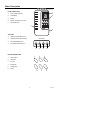
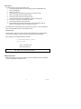
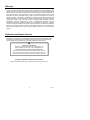
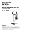
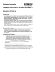
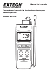
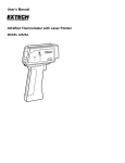
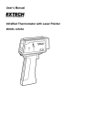
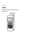
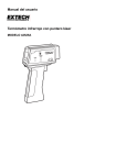
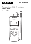
User's Guide
Heavy Duty Datalogger Module
Model 380340
Introduction
Congratulations on your purchase of Extech’s 380340 Datalogger Module. The
Datalogger connects to and records data from Extech Heavy Duty Series Meters. The
sample rate at which data is recorded is user selectable. Readings stored in the
Datalogger can later be transferred to a PC using the supplied software and
communication cables. This device is shipped fully tested and, with proper use, will
provide years of reliable service.
Meter Description
1
FRONT PANEL VIEW
1.
Input / Output terminals
2.
LCD Display
3.
Buttons
4.
Battery compartment (on rear)
5.
AC adaptor input
AUTO MANUAL %
REC
OUT
2
3
5
4
TOP VIEW
1.
Optically isolated INPUT jack
2.
Optically isolated OUTPUT jack
3.
Non-isolated INPUT jack
4.
Non-isolated OUTPUT jack
TOP VIEW
IN
ISOLATE
OUT
1
BUTTON DESCRIPTION
1.
Power switch
2.
Date/Time
3.
Function
4.
Enter/Clear
5.
Sample Rate
6.
Pause
2
1
DIRECT
OUT
3
2
4
2
IN
4
3
5
6
V5.0 5/06
Compatible Meters
Model No.
Meter Type
Display
In/Out Port
COM Cable
407026
Light Meter
Single
Direct
UPCB-01
407112
Vane Anemometer
Dual
Direct
UPCB-01
407113
Vane Anemometer
Dual
Direct
UPCB-01
407114
CFM Thermo-Anemometer
Dual
Direct
UPCB-01
407117
Mini Vane Thermo-Anemometer
Dual
Direct
UPCB-01
407119
Hot Wire CFM Anemometer
Dual
Direct
UPCB-01
407119A
Hot Wire CFM Anemometer
Dual
Isolated
UPCB-02
407123
Hot Wire Anemometer
Dual
Direct
UPCB-01
407227
pH / mV / Temperature
Dual
Direct
UPCB-01
407303
Conductivity Meter
Dual
Direct
UPCB-01
407401
Dual Thermometer
Dual
Direct
UPCB-01
407412
Thermo-Anemometer / Humidity
407428
IR Thermometer
407445
RH / Temperature Meter
407495
Pressure meter
407510
Dissolved Oxygen (DO) Meter
Dual
Direct
UPCB-01
Single
Direct
UPCB-01
Dual
Direct
UPCB-01
Single
Direct
UPCB-01
Dual
Direct
UPCB-01
407768
Sound Level Meter
Single
Isolated
UPCB-02
407777
Moisture Meter
Single
Direct
UPCB-01
407820
Torque Meter
Single
Direct
UPCB-01
407850
Vibration Meter
Single
Direct
UPCB-01
407907
RTD Thermometer
Single
Direct
UPCB-01
407910
Differential Pressure Manometer
Single
Direct
UPCB-01
42525A
IR Thermometer
Single
Isolated
UPCB-02
475055
Force Gauge
Single
Direct
UPCB-01
3
V5.0 5/06
Operation
Note: The Heavy Duty Meters have an Auto-Shutoff feature that automatically turns off the
meter (after 10 to 30 minutes depending on the model). This feature must be disabled during
a datalogging session. Press the ‘RECORD’ button on the meter to disable the Auto-Shutoff
feature.
Setting the Date and Time
The actual date and time should be programmed into the data logger prior to use. To
program the date and time:
1.
Turn the data logger on.
2.
Press the Date/Time button to enter the date and time setting mode.
3.
While in the date and time setting screen hold down the Date/Time button until
“SET” appears on the screen, then release the Date/Time button. The screen will
begin blinking.
4.
While the screen is blinking, pressing the Date/Time button allows the user to
scroll through Year, Month, Date, Hour, Min and Sec.
5.
While the screen is still blinking, press the up arrow, (Function Button), to
adjust the number on the screen to the desired year, month, date, etc. Holding the
up arrow button down allows for rapid changing of the numerical value.
6.
When the desired date and time is programmed, the logger will exit the time and
date setting function after a few seconds with no button presses.
Automatic Datalogging
This function sets the Datalogger to automatically collect readings at a sample rate set by
the user.
1. Connect the Dataloggers IN port to the Heavy Duty Meter
as shown in the illustration. (The supplied UPCB-03) cable
connects the meter to the Datalogger). Use the Isolated or
Direct port on the Datalogger according to the chart on
page 3.
2. Turn the power on.
3. Press the Function button until AUTO is displayed on LCD.
4. To set a new recording interval Press and Hold Sample Time button until display
flashes SET and HOUR.
Press ↑↓ to set hour. Then press Sample time to go to minutes
Press ↑↓ to set minutes. Then press Sample time to go to seconds
Press ↑↓ to set seconds. Then press Enter to save your interval setting.
Begin Automatic Datalogging
1.
Press the PAUSE button to begin logging. The display will change from PS to RC
and begin logging.
2.
Press PAUSE again the stop logging.
3.
Use the PAUSE button to toggle recording ON (resume) and OFF (pause). When
datalogging is resumed, new readings are recorded right where the datalogger left
off so that readings are not overwritten.
4
V5.0 5/06
Clearing Logger Memory
1.
Press and hold Clear button until CLR appears and display begins to flash. The
number displayed shows the % of memory used.
2.
Press ↑↓ to select YS (Yes)
3.
Press Enter. Display will flash 00. Memory is now clear.
NOTE: Data will remain in memory until the Datalogger memory is cleared (see previous
section) or until the batteries are removed.
Manual Datalogging
Manual datalogging allows the user to record one reading at a time.
1.
Turn the Datalogger On.
2.
Press the Function button until MANUAL is displayed on the LCD.
3.
Press the PAUSE button to log one measurement. Display will change from PS to
RC and return to PS each time a recording is made..
5
V5.0 5/06
Transferring Data to a PC
Once data is collected, the next step is to connect the Datalogger to a PC and transfer the
collected readings.
Hardware Connection
Connect the Datalogger’s OUT port to the PC COM port
(as shown) via the supplied 3.5mm phono to DB-9 cable.
Refer to the compatible meter list for the correct cable and
“OUT” port for your meter..
TM
Windows
AUTO MANUAL %
REC
OUT
Datalogger Software
TM
Install the supplied software from the Windows program CD-ROM using the instructions
provided on the CD-ROM. The following software screen will appear.
Software Screen Description
2
1
5
4
6
3
1.
2.
3.
4.
5.
6.
7.
7
COM Port Selection (Use pull down menu to select port)
Data Transfer Status
Transferred Data View
Data File Name (type desired filename)
Number of readings
Instructional steps describing the data transfer process (additional steps are listed
in the next section).
Function buttons: START (click to begin data transfer); VIEW DATA (click to see all
transferred data as shown in item 3 above), and EXIT (click to close program)
6
V5.0 5/06
Data Transfer
To transfer data from a Heavy Duty meter to a PC.
1. Connect appropriate cable to PC and the logger. (See Compatible Meter List)
2. Power the Datalogger.
3. Select your com port.
4. Type a file name in the Data File Name field on the software screen.
5. Click on the START key in the software window
6. Press the Function button until LCD displays OUT
7. Press the PAUSE button on the Datalogger to begin the data transfer.
8. The LCD will count down as it transfers your data.
9. Press the PAUSE button to halt the transfer.
10. After the data points have been transferred, turn off the datalogger. Data will
remain in the datalogger as long as the batteries are fresh.
The data points are transferred to the file named in step 4 above. To view the transferred
data, click the VIEW DATA button on the software screen.
Record Format
The file stored on the PC can now be opened in other applications such as spreadsheet,
word-processor, database or graphics programs. Records are comma delimited.
When imported, each reading will appear as follows.
1,"060306120458","Time"
2,1173,"LUX
"
Row ID, Time stamp, Unit
Row ID, Reading, Unit
Note: Each time stamp is saved as a 16 character reading as follows.
Year, Month, Day, Hours, Minutes, Seconds
Battery Replacement
Slide the rear battery cover off in the direction of the arrow. Replace the four ‘AA’ batteries
and secure the battery compartment cover.
7
V5.0 5/06
Specifications
Input type
RS-232 data stream
Data storage
8000 readings (16 bits each)
Display
LCD
Adjustable Sample Rate
1 second to 8hrs 59 minutes 59 seconds
Software compatibility
WindowsTM 98, 2000, Me, and XP Operating Systems
Internal Clock
Crystal oscillator
Memory
Non-volatile; Data is retained at power down
Batteries
Four 1.5V AA batteries (alkaline or heavy duty type)
Battery life
36 hours continuous (typical)
Power consumption
Approx. 3.7mA DC
Operating temperature
32 to 122 F (0 to 50 C)
Operating humidity
< 80 % RH
o
o
Weight
0.45 lbs. (205g) including battery
Dimensions
5.2 x 2.8 x 1.0" (131 x 70 x 26mm) (H x W x D)
8
V5.0 5/06
Warranty
EXTECH INSTRUMENTS CORPORATION warrants this instrument to be free of defects
in parts and workmanship for one year from date of shipment (a six month limited warranty
applies to sensors and cables). If it should become necessary to return the instrument for
service during or beyond the warranty period, contact the Customer Service Department at
(781) 890-7440 ext. 210 for authorization or visit our website www.extech.com for contact
information. A Return Authorization (RA) number must be issued before any product is
returned to Extech. The sender is responsible for shipping charges, freight, insurance and
proper packaging to prevent damage in transit. This warranty does not apply to defects
resulting from action of the user such as misuse, improper wiring, operation outside of
specification, improper maintenance or repair, or unauthorized modification. Extech
specifically disclaims any implied warranties or merchantability or fitness for a specific
purpose and will not be liable for any direct, indirect, incidental or consequential damages.
Extech's total liability is limited to repair or replacement of the product. The warranty set
forth above is inclusive and no other warranty, whether written or oral, is expressed or
implied.
Calibration and Repair Services
Extech offers repair and calibration services for the products we sell. Extech also
provides NIST certification for most products. Call the Customer Service Department for
information on calibration services available for this product. Extech recommends that
annual calibrations be performed to verify meter performance and accuracy.
Support line (781) 890-7440
Technical support: Extension 200; E-mail: [email protected]
Repair & Returns: Extension 210; E-mail: [email protected]
Product specifications subject to change without notice
For the latest version of this User’s Guide, Software updates, and other
up-to-the-minute product information, visit our website: www.extech.com
Extech Instruments Corporation, 285 Bear Hill Rd., Waltham, MA 02451
Copyright © 2006 Extech Instruments Corporation
All rights reserved including the right of reproduction in whole or in part in any form.
9
V5.0 5/06