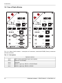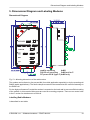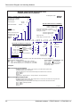
1
Operating manual . Wideband modems – PROFI MX160 . version 1.8 3/31/2015 RACOM s.r.o. • Mirova 1283 • 592 31 Nove Mesto na Morave • Czech Republic Tel.: +420 565 659 511 • Fax: +420 565 659 512 • E-mail: [email protected] www.racom.eu Table of Contents Introduction .......................................................................................................................................... 5 1. Radio modem MX160 ...................................................................................................................... 6 2. Description of Radiomodem MX160 ............................................................................................... 7 2.1. Radio part ............................................................................................................................. 7 2.2. Modem part .......................................................................................................................... 7 2.3. Supplying .............................................................................................................................. 7 2.4. Radio Modem Assembly ...................................................................................................... 7 3. Connectors ...................................................................................................................................... 9 3.1. Antenna ................................................................................................................................ 9 3.2. Serial Interface ..................................................................................................................... 9 3.3. Ethernet .............................................................................................................................. 11 3.4. Analog and Digital Inputs and Outputs ............................................................................... 12 3.5. Supply Connector ............................................................................................................... 14 3.6. Information LED ................................................................................................................. 14 3.7. Service Connector .............................................................................................................. 14 3.8. View of Radio Modem ........................................................................................................ 16 4. Table of Technical Parameters ...................................................................................................... 17 5. Dimensional Diagram and Labeling Modems ............................................................................... 19 6. Condition for MX160 ...................................................................................................................... 21 6.1. Important Warning .............................................................................................................. 21 6.2. Conditions of Liability for Defects and Instructions for Safe Operation of Equipment. ....... 21 6.3. RoHS and WEEE compliance ............................................................................................ 22 6.4. Product Conformity ............................................................................................................. 23 6.5. Country of Origin ................................................................................................................ 25 6.6. Limitations of Use ............................................................................................................... 26 A. Revision History ............................................................................................................................ 27 List of Figures 1. Radio modem MX160 with Cannon connectors .............................................................................. 5 2. Radio modem MR160 with screw clamps, MR300 with Cannon connectors and MR400 with Cannon connectors ............................................................................................................................. 5 3.1. RS232 DSUB9 female .................................................................................................................. 9 3.2. Data cable RS485 connections .................................................................................................. 10 3.3. Labelling of serial interface terminals ......................................................................................... 11 3.4. RJ-45F ........................................................................................................................................ 12 3.5. Wiring diagrams for analog and digital inputs and outputs ........................................................ 12 3.6. Description of analog and digital inputs and outputs .................................................................. 13 3.7. Examples of wiring analog inputs and outputs ........................................................................... 13 3.8. Power connector & information LED .......................................................................................... 14 3.9. Service connector ....................................................................................................................... 14 3.10. Service cable connector connections ....................................................................................... 15 3.11. View of radio modem — description of connectors, model with DSUB (Canon) connectors and with terminals ............................................................................................................................. 16 5.1. Mounting dimensions of the radiomodem .................................................................................. 19 6.1. Warning sticker IEC 60417-5041 (DB:2002-10) ......................................................................... 22 6.2. Consistency declaration ............................................................................................................. 24 6.3. Country of Origin declaration ..................................................................................................... 25 © RACOM s.r.o. – Wideband modems – PROFI MX160 3 Wideband modems – PROFI MX160 List of Tables 3.1. Table of data connector RS232 connections ................................................................................ 9 3.2. Table of data connector RS422 connections .............................................................................. 10 3.3. Table for distinguishing LEDs for RxD and TxD by colour ......................................................... 10 3.4. Table of Ethernet to cable connector connections ..................................................................... 12 3.5. Table of digital and analog input and output parameters ........................................................... 13 3.6. Table of service connector connections ..................................................................................... 14 3.7. Slot options ................................................................................................................................. 16 4.1. Table of technical parameters MX160 ........................................................................................ 17 4.2. Standards complied .................................................................................................................... 18 4.3. Standards complied for Railway Safety Appliance Standards Regulations ............................... 18 4 Wideband modems – PROFI MX160 – © RACOM s.r.o. Introduction Introduction This operator manual serves as the primary document for familiarising users with the parameters of the radio modem MX160, its properties, modifications and with the parameters of connecting parts. This controller is part of the MORSE system, is fully compatible with other modems, and because it is derived from previously developed types it has similar mechanical parameters to them, as well as all interfaces, the modem part and firmware. For this reason modem MR400 images are often used in other parts of the manual. In order to master all the functions of the radio modem and the MORSE system you should refer to other documents. Fig. 1: Radio modem MX160 with Cannon connectors Fig. 2: Radio modem MR160 with screw clamps, MR300 with Cannon connectors and MR400 with Cannon connectors © RACOM s.r.o. – Wideband modems – PROFI MX160 5 Radio modem MX160 1. Radio modem MX160 MX160 is conceptually new radio modems designed for transmitting data in the VHF and UHF bands. The radio modem uses 2-state GMSK modulation providing for a maximum signalling rate of 133 kbit/s. The radio modem is of modular design with one to four standard RS232 ports (an RS422 or RS485 port can be used in place of two of them) available to the user. The configuration can be extended by an Ethernet interface and also by a module with analog and digital inputs/outputs. It is generally manufactured with two analog inputs and outputs and with two digital inputs and outputs. The radio data transceiver module can be configured to a random frequency of the transmitter and receiver in the 3.2 MHz frequency range in a 25 kHz channel raster. The output and input working frequencies are mutually independent and are derived from the frequencies of four phase-hung systems programmed by the transceiver microprocessor. Channel settings are stored in the transceiver FLASH memory and the FLASH memory module of the modem whose communication processor controls the operation of the transceiver microprocessor. The power of the radio modem transmitter is digitally set in sixteen steps from 0.1 to 25 W. The design and construction of this device allows for long-term loading and for this reason it is primarily determined for continuously running applications. Software control is compatible with the operation and configuration of the other radio modems of the MORSE system. A description of software control and configuration is available in publications describing MORSE Firmware. Important The radio modem is equipment which can only be operated in the state on the basis of Permission to operate transmitting radio stations issued by the Department of Frequency Spectrum Management at the national Telecommunication Office. 6 Wideband modems – PROFI MX160 – © RACOM s.r.o. Description of Radiomodem MX160 2. Description of Radiomodem MX160 2.1. Radio part The architecture of MX160 radio modems resolves most of the requirements placed on a top quality user friendly radio modem with a very short switching time between receiving and transmitting. Frequency synthesis enables operation on any random channel from a given frequency band. The operation of the radio data transceiver module is controlled and diagnosed by the micro-controller. The receiving part of the radio modem works with double mixing. Concentrated selectivity is divided between both intermediate frequency levels. The first filter carries out basic channel pre-selection up until attenuation which ensures the linear function of the following second mixer and intermediate frequency amplifier. The second filter of concentrated selectivity has an attenuation characteristic necessary for channel selection in the used channel spacing of 200 kHz. Logic circuits, switching stations between modes of receiving and transmitting, have high noise immunity and switch respective blocks sequentially. This minimises most transient parasite states and optimises bandwidth during switching. Station block modes are logically tied and switching of the station to transmitting mode is tied to the frequency synthesiser lock, the internal temperature of the radio transceiver module and the value of the supply voltage. 2.2. Modem part The control microcomputer has 4 MB of FLASH memory and 16 MB of RAM memory available. The battery, real time backup supply, detector of supply voltage failure and watch dog circuits belong amongst the other circuits of this block. If there is a supply voltage failure the fact is recorded into memory with the respective time data thanks to the charge stored in electrolytic capacitors. The user therefore has information available about the time and duration of possible faults caused by power failures. It is possible to connect equipment with signalling rates up to 115.2 kbit/s to the modem via the RS232 data interface. RS232 interface converters are protected against overvoltage with TRANSIL elements. A lithium battery is used for backing up in the modem part. Note Owing to the use of lithium batteries in the modem part it is not recommended to store them for a period of longer than 2 years. 2.3. Supplying The radiomodem is supplied by the DC current 13.8 V. The consumption in the quiet state is from 350 to 500 mA according to module used, the consumption at transmitting is up to 2 A. The modem can be set in the SLEEP mode when the consumtion drops down to 2.5 mA. The return in the active mode can be done by the signal inputting on the serial port or after a preset time. 2.4. Radio Modem Assembly Radio modems MX160 are special devices which require skilled assembly. All supplied equipment is assembled by RACOM at the user’s site. For subsequent maintenance RACOM specially trains the user’s skilled staff and as an additional aid provides them with Operating regulations for radio data networks and MORSE Firmware – Documentation. © RACOM s.r.o. – Wideband modems – PROFI MX160 7 Description of Radiomodem MX160 Important CAUTION! Danger of explosion upon replacing the incorrect type of battery. Follow the manufacturers instructions for handling used batteries. 8 Wideband modems – PROFI MX160 – © RACOM s.r.o. Connectors 3. Connectors 3.1. Antenna The radio modem is fitted with two SMA type connectors for connecting an antenna. The connector labelled Rx is for the receiver, and Tx for the transmitter (up to 25 W). Use the corresponding type of connector with matched impedance as the mate. We recommend an RG158 cable for the serial lead. Important The radio modem cannot be connected to the power supply without the antenna connected (or corresponding artificial load). Otherwise this could lead to damage to the radio part of the modem. 3.2. Serial Interface The router can be equipped with serial ports RS232 or RS422/485, the ports can be optical isolated. According to the configuration it is possible to use a terminal block or DSUB 9 (Canon) connectors for connecting data cables via the serial interface. See Chapter Dimensional Diagram and Labeling. Data rate on the serial interface can be from 200 bps to 230,400 bps. 3.2.1. RS232, RS422 and RS485 Connectors a) Table of data connector RS232 connections Tab. 3.1: Table of data connector RS232 connections RS232 signal Screw DSUB9F terminals pin CTS 1 8 RTS 2 7 RxD 3 2 TxD 4 3 GND 5 5 DTR 4 DSR 6 CD 1 RI 9 © RACOM s.r.o. – Wideband modems – PROFI MX160 Fig. 3.1: RS232 DSUB9 female 9 Connectors b) Table of data connector RS422 connections Tab. 3.2: Table of data connector RS422 connections RS422 signal Screw DSUB9F terminals pin TxD- 1 7 TxD+ 2 3 RxD- 3 8 RxD+ 4 2 GND 5 5 c) Connection diagram of data cable RS485 When you are connecting RS485, your “A” has to be connected to TxD+ and RxD+ simultaneously and “B” to TxD- and RxD- simultaneosly. Screw terminals for RS485 line B line A 1 2 3 4 5 DSUB9F SCC line A (+) 4 3 2 1 5 9 8 7 6 RS485 RS485 line B (–) Fig. 3.2: Data cable RS485 connections Note - For data connector RS485 connection see Table of data connector RS422 connections. Important - For making data cables for connecting the user´s terminal equipment to the serial port we recommend using a shielded cable, particularly in an industrial environment, and connecting the shielding to GND (pin No. 5). When using a multi-core cable all free conductors should be connected to pin No. 5. In the case of a galvanically separate port for RS485 (RS422) only ground one side of the data cable. We recommend using only the necessary minimum length for data cables. 3.2.2. Distinguishing Data Modules by Colour For RS232 RxD is the output from the router (approx. -6V when inactive) and TxD is the input to the router (according to the RS 232 standard). Hardware versions of the interface can be distinguished according to the colours of LED diodes next to the connector. Tab. 3.3: Table for distinguishing LEDs for RxD and TxD by colour Type of interface Colour (RxD / TxD) RS232 red / green RS232 opt. separated orange / green RS422/485 opt. separated orange / yellow 10 Wideband modems – PROFI MX160 – © RACOM s.r.o. Connectors 3.2.3. Labelling of SCC terminals MORSE ROUTER PLC RxD RxD Red LED DCE DTE TxD Green LED TxD Fig. 3.3: Labelling of serial interface terminals The SCC ports of the router are DCE type devices. Based on standards the receiver terminal RxD of the connected DTE device is connected to the transmitting terminal of the router's SCC port which is also labelled RxD. Similarly the red LED indicating transmission from SCC is labelled RxD. 3.3. Ethernet • Connector RJ-45 for Ethernet 10BaseT and 100BaseT corresponds to the EIA TIA T568B standard. • Informative LED diodes indicate: ○ Tx – yellow - output or input active (*Tx - red - output from ETH channel) ○ Rx – yellow - output or input active (*Rx - green - input to ETH channel Note Green LED Tx and yellow LED Rx flash simultaneuosly. The informations marked (*) are valid for hw version produced until 07/2008. ○ 100 – yellow - if lit the 100Base-TX net is indicated otherwise is 10Base-T ○ LINK – green - indicates correctly connected link ○ F.D. – green - indicates full duplex operation • The direct cable serves for connecting to the Ethernet network via the hub (repeater) or switch-hub (router). • A crossed cable serves for connecting only two devices - MR400-MC100, MR400-PC, etc. The ETH module consumption is 30 mA (60 mA until 07/2008). The following table contains connector connections and colours of conductors. For the crossed cable the order of conductors on one side is the same as for the direct cable. © RACOM s.r.o. – Wideband modems – PROFI MX160 11 Connectors Tab. 3.4: Table of Ethernet to cable connector connections PIN Signal Direct cable Crossed cable 1 TX+ white - orange white - green 2 TX- orange green 3 RX+ white - green white - orange 4 — blue blue 5 — white - blue white - blue 6 Rx- green orange 7 — white - brown white - brown 8 — brown brown Fig. 3.4: RJ-45F 3.4. Analog and Digital Inputs and Outputs The module of analog and digital inputs and outputs (ADIO) is designed for : • creating 20 mA current loops • switching loads supplied with DC and AC current • scanning digital signals Each functional group of terminals is galvanically separated from the rest of the device as shown on the internal layout diagram for the ADIO module on the image below: +A OUT 0 +A IN 0 +A OUT 1 +A IN 1 A OUT 0, 1 Analog outputs D OUT 0 +DIN 0 D OUT 0 D OUT 1 DIN 0 +DIN 1 D OUT 1 DIN 1 Digital outputs Digital inputs A IN 0, 1 Analog inputs Fig. 3.5: Wiring diagrams for analog and digital inputs and outputs 3.4.1. Labelling Individual terminals of terminal blocks are labelled: Connector A OUT - analog outputs Connector A IN - analog inputs Connector D OUT - digital outputs Connector D IN - digital inputs Terminal UP this clamps pair is not used 12 Wideband modems – PROFI MX160 – © RACOM s.r.o. Connectors D OUT + – + – 0 1 D IN 0 1 UP 0 + – + – + – A IN 1 0 + – + – 1 + – + – A OUT Fig. 3.6: Description of analog and digital inputs and outputs 3.4.2. Parameters Tab. 3.5: Table of digital and analog input and output parameters – bipolar SSR switch design – voltage for supplying load max. 30 V DC, 24 V AC 2 × optically separated – switched current typically 300 mAresistance in on state passive digital output max. 1 Ω – protection against current overload in on state – protection against overvoltage in off state – passive optical element design 2 × optically separated – input voltage 0–2,3 V will be evaluated as log. 0 digital input – input voltage 2–30 V will be evaluated as log. 1 – max. value of input voltage 30 V – current source 4–20 mA 2 × optically separated – load resistance max. 250 Ω analog output – settings accuracy better than 0.1 % – sensitivity 0–20 mA (or after sw configuration 4–20 mA) – accuracy of measured values better than 0.1 % 2 × optically separated – input resistance 60 Ω analog input – no protection against current overload – max. value of input current 50 mA passive active passive Analog inputs 0 and 1 have - (minus) terminals connected and galvan. separated from router GND. Analog outputs 0 and 1 have - (minus) terminals connected and galvan. separated from router GND. +A out +A in technology -A out MORSE router +A in -A in with an active +A out -A in -A out +A out + - -A out MORSE router +A in -A in current loop transmitter or MORSE router voltage supply + = - + - technology, passive current loop transmitter The MORSE router used in the diagram showing examples of wiring can, of course, be replaced by any MORSE system equipment (e.g. MD160, MX 160, MWxxx, MRxxx, MC100, MG100i, ...) Fig. 3.7: Examples of wiring analog inputs and outputs © RACOM s.r.o. – Wideband modems – PROFI MX160 13 Connectors 3.5. Supply Connector Terminals of this connector are labelled in the standard manner. Only DC voltage in the range from 10.8 to 15.6 V can be connected. Connecting higher voltage may damage the radio modem. Terminal PI (power indicator) - if the radio modem is fed from the MS2000 power supply information about supply method from source clamp MAIN PWR OFF can be lead: • level TTL1 or unconnected clamp - network supply • level TTL0 or grounded clamp - battery supply Maximal supply cable length is 3 m. 3.6. Information LED Fig. 3.8: Power connector & information LED Information LED diodes next to the supply connector: • RF Tx — radio modem transmits RF frequency into antenna • RS SYNC — radio modem received message header which was determined for it • Three following LED (signal strength): ON • ON ON RSS -85dBm and stronger OFF ON ON RSS -85 až -95dBm OFF OFF ON RSS -95 až -115dBm OFF OFF OFF RSS -115dBm and weaker POWER ON — radio modem is correctly supplied 3.7. Service Connector The service connector RJ-12 serves for short-term connections of the service cable during local adjustment of MORSE router parameters. Upon attaching the connector (connecting to the RS232 link (RxD,TxD, GND)) the router automatically switches to service mode and the module slot 1 disconnects. Slots numbering see section Section 3.8, “View of Radio Modem”. Tab. 3.6: Table of service connector connections 1 AF_OUT output of modulation from RF part of router 2 SER_RxD RS232 RxD output from router 3 SER_TxD RS232 TxD input to router 4 MOD_BSB input modulation to radio part of router Fig. 3.9: Service connector 5 GND ground 6 PTT keying of TX carrier waves for service purposes Important ATTENTION! The service mode is not suitable for normal operation 14 Wideband modems – PROFI MX160 – © RACOM s.r.o. Connectors RX data TX data GND pin 2 pin 3 Cannon DSUB9F pin 5 1 23456 Fig. 3.10: Service cable connector connections © RACOM s.r.o. – Wideband modems – PROFI MX160 15 Connectors 3.8. View of Radio Modem Tx Tx A OUT 1 A IN 1 0 D OUT 0 1 0 D IN 1 POWER ON A OUT UP 0 1 POWER A IN 1 0 SERVICE PI + + GND GND RF Tx SERVICE PI + + GND GND POWER RF SYNC POWER ON Rx RF SYNC RF Tx Rx D OUT 0 1 D IN 0 1 UP 0 SCC3 SLOT 3 + – + – + – + – + – + – + – 100 F. D. CTS RTS TxD RxD GND 3 4 5 1 2 3 4 5 Rx Tx 2 Rx Rx Tx SLOT 1 SCC0 1 SCC1 Tx Rx Tx SLOT 2 SCC1 SCC3 2 CTS 2 SCC2 3 RTS TxD RxD GND 3 LINK Rx Rx ETH0 Tx Rx Tx SCC2 + – + – + – + – + – + – + – SLOT 4 ETH0 Tx LINK F. D. 100 Rx Tx + – + – + – + – SLOT 5 SCC0 Fig. 3.11: View of radio modem — description of connectors, model with DSUB (Canon) connectors and with terminals Tab. 3.7: Slot options Optional modules 16 slot 5 ADIO (analog and digital inputs and outputs) slot 4 Ethernet 10/100 Mbps slot 3 2×RS232 slot 2 RS232 or galv.sep. RS232 or RS422/RS485 slot 1 RS232 or galv.sep. RS232 or RS422 Wideband modems – PROFI MX160 – © RACOM s.r.o. Table of Technical Parameters 4. Table of Technical Parameters Tab. 4.1: Table of technical parameters MX160 Tx: 154,725–159,725 MHz/159,325–164,325 MHz Frequency range Rx: 159,325–164,325 MHz/154,725–159,725 MHz Channel spacing 200 kHz Means of setting working frequency -3 Receiver sensitivity for BER 10 Software adjustable output power software in range +3.2 MHz from base frequency better than -104 dBm 1) 0.1–5 W 0.1–25 W Max. modulation rate for transmitting 133 kbit/s in 200 kHz channel Optional modules slot 5 ADIO (analog and digital inputs and outputs) slot 4 Ethernet 10/100 Mbps slot 3 2×RS232 slot 2 RS232 or galv.sep. RS232 or RS422/RS485 slot 1 RS232 or galv.sep. RS232 or RS422 Antenna connector SMA + SMA MTBF(Mean Time Between Failure) > 500.000 hours (> 50 years) Supply nominal voltage 13.8 V Supply voltage range 10.8–15.6 V Idle consumption (Rx) 2) Transmission consumption (Tx) 420 mA + modules: (Eth. 30 mA, ADIO 50 mA, SCC 5 mA) 2) 5.5 A / 25 W Consumption in SLEEP mode 2.5 mA Operating range of temperature -25 to +55 °C Storage range of temperature -40 to +85 °C Mechanical dimensions 208×108×63 mm (71 mm DIN rail including) 184×108×63 mm (short version) Spacing of fastening holes 198×65 mm, ø 4.8 mm Weight 1.3 kg 1 2 1) Availability of specific types and frequencies check here , please. Presently these types are under mass production. 2) Approximate values dependent on frequency and modem type. 1 2 http://www.racom.eu/eng/products/rfp.html http://www.racom.eu/eng/products/radio-modems-mr400.html#specifications © RACOM s.r.o. – Wideband modems – PROFI MX160 17 Table of Technical Parameters Tab. 4.2: Standards complied EMC (Electromagnetic Compatibility) ETSI EN 301 489-5 V 1.3.1 Radio parameters ETSI EN 300 908-9 V 1.1.1 (2002-01), ETSI EN 300 113-1 V 1.5.1 (2003-09) Electrical safety CSN EN 60 950:2001 Wheeled vehicle usage UN Regulation No.10 (EHK No.10) Tab. 4.3: Standards complied for Railway Safety Appliance Standards Regulations nd Electronic appliances in railway vehicles CSN EN 50155 ed. 2 : 2002. art. 10.2.8.2 CSN EN 50121 art. 7: tab. 3 and 4 EMC (Electromagnetic Compatibility) CSN EN 50121-3-2 art. 8 Vibrations and beats CSN EN 61373 18 Wideband modems – PROFI MX160 – © RACOM s.r.o. Dimensional Diagram and Labeling Modems 5. Dimensional Diagram and Labeling Modems Dimensional Diagram mobile mounting 4×M4 DIN 35 rail mounting 2×M4 not for P RF power 25 W (type P) 4×M4 only Fig. 5.1: Mounting dimensions of the radiomodem The modem can be fasten by four screws M4 (for mobile application especially) or by the mounting rail DIN35 (stable applications). The flexile clamps mounted in the central holes are used for fastening on the DIN35 rail. For the high-performance P model the modem is mounted on the back wall to ensure sufficient cooling of the modem. In this case 4x M4 screws are used for mounting purposes. There are no centre holes in the P version for attachment to a DIN rail. Labelling Radio Modems is described in next table: © RACOM s.r.o. – Wideband modems – PROFI MX160 19 Dimensional Diagram and Labeling Modems MORSE components production code radiomodems profi wideband RADIO CHANNEL AND CASE VERSION: SCC with Cannon DSUB9 SCC with screw terminals SCC not used Frequency step –C –S –N 25 kHz 10 kHz Channel bandwidth For equipment series: –5 –3 DIGITAL AND ANALOG CHANNELS: – 4 200 kHz MW160 MX160 number of Analog outputs number of Analog inputs CASING Analog input and output 0 - 20 mA -A An input 0 - 1240 mV, An output 0 - 20 mA - V Analog I/O not used - empty -P RF power 25 W Base Tx frequency, MHz number of Digital outputs number of Digital inputs Half-duplex radio - W Full-duplex radio - X Digital I/O used neither Dig nor An I/O are used MORSE PROFI -D -N MW161.0P45C-N-485I-232-E-D22A22 SETTING OF MODULE POSITION: (from bottom edge of case) red green orange green orange yellow LED – RxD TxD SCC0 Line type: RS232 232 optically separated: 232I RS232 RS422/485 unused position N SCC1 232 ETH0 SCC2 SCC3 232 Digital I/O + Analog I/O 232I 485I N LED colours tell the interface type N Ethernet present unused position E N N Comment - radiomodem is the DCE equipment - both data output RS232 pin and LED are labeled RxD. Base frequency labelling options: MW: 161.0 = base freq. 161.0 MHz, both Tx and Rx MX: 161.0 / 156.4 = base freq. Tx = 161.0 MHz, Rx = 156.4 MHz 156.4 / 161.0 = base freq. Tx = 156.4 MHz, Rx = 161.0 MHz Typical example of bandwidth/freq. step: before 12/2008 after 12/2008 MW161.0M4C-... MW161.0M45C-... The standard freq. step is 25 kHz, exceptionally 10 kHz. Examples: MW161.0P45C-N-N-232-E-D22A22 = MORSE half-duplex radio modem, base frequency 161,000 MHz, RF power 25W, bandwidth 200 kHz, freq. step 25 kHz, casing with flanges for screws and/or DIN rail clips, SCC with Cannon connectors, SCC2 - RS232, SCC3 - RS232, Ethernet, Digital input 2×, Digital output 2×, An input 20mA 2×, An output 20mA 2× MX161.0/156.6M45S-N-485I-232-E-N = MORSE full-duplex radio modem, base frequencies Tx=161.0 MHz, Rx=156.6 MHz, RF power 25W bandwidth 200 kHz, freq. step 25 kHz, casing with flanges for screws and/or DIN rail clips, SCC connectors with screw terminals, SCC1 - RS485, optically separated, SCC2 - RS232, SCC3 - RS232, Ethernet 07 2014 20 Wideband modems – PROFI MX160 – © RACOM s.r.o. Condition for MX160 6. Condition for MX160 6.1. Important Warning RACOM s. r. o. (hereinafter referred to as RACOM) is the exclusive owner of all rights to this operator manual. All rights reserved. Any duplication of this manual in any way, shape or form, or translation to any other language (without the prior written consent of the owner of the rights) is strictly forbidden. RACOM retains the right to make changes to the technical specification or functions of this product or to terminate production of this product, or to terminate service support of this product without advance written notice to the customer. RACOM firmware is available free of charge. Source code is the property of RACOM and is not available to any user. Any commercial use of the software with this licence is strictly forbidden. Changes to software and documentation are forbidden. RACOM firmware is released with the intention that it will be useful, however without any specific guarantees. Under no circumstances is the Racom or any other company or person responsible for incidental, accidental or related damage arising as a result of the use of this product. The manufacturer shall not provide the user with any form of guarantee containing assurance of the suitability and applicability for its application. RACOM products are not developed, designed or tested for use in equipment which directly affects the health and life functions of humans or animals and neither as part of other important equipment, and RACOM does not provide a guarantee if company products are used in such equipment. 6.2. Conditions of Liability for Defects and Instructions for Safe Operation of Equipment. Please read these safety instructions carefully before using the product: • Liability for defects does not apply to any product that has been used in a manner which conflicts with the instructions contained in this operator manual, or if the case in which the radio modem is located has been opened, or if the equipment has been tampered with. • The radio modem can only be operated on frequencies stipulated by the body authorised by the radio operation administration in the respective country and cannot exceed the maximum permitted output power. RACOM is not responsible for products used in an unauthorised way. • Equipment mentioned in this operator manual may only be used in accordance with instructions contained in this manual. Error-free and safe operation of this equipment is only guaranteed if this equipment is transported, stored, operated and controlled in the proper manner. The same applies to equipment maintenance. • In order to prevent damage to the radio modem and other terminal equipment the supply must always be disconnected upon connecting or disconnecting the cable to the radio modem data interface. It is necessary to ensure that connected equipment has been grounded to the same potential. Before connecting the supply cable the output source voltage should be disconnected. • Only undermentioned manufacturer is entitled to repair any devices. • CAUTION ! Risk of explosion on replacing the incorrect type of battery in the modem part. Dispose of used batteries in accordance with their manufacturer's instructions. We recommend that lithium back-up batteries are replaced by RACOM service agents. • For ensuring the appropriate protection the manufacturer recommends powering the radio modem from an MS2000 power supply with short circuit current protection which acts as means of current © RACOM s.r.o. – Wideband modems – PROFI MX160 21 Condition for MX160 protection for output circuits. If another power supply is used fuses, overcurrent protection or similar protective components should be used. ○ In threshold mode the radio modem is capable of operation at an ambient temperature of up to 70 °C. In such cases the temperature of the surface of the radio modem may reach high values, particularly in the case of the high end model "P" – the modem temperature may be up to several tens of degrees hotter than the ambient temperature, and therefore under these conditions the equipment needs to be protected against accidential contact. We recommend that operators who plan on using this threshold mode stick a warning sticker, in accordance with IEC 60417-5041 (DB:2002-10), on a visible part of the radio modem, or attach a sticker with the following text: CAUTION! HOT SURFACE DO NOT TOUCH Fig. 6.1: Warning sticker IEC 60417-5041 (DB:2002-10) 6.3. RoHS and WEEE compliance The routers are fully compliant with the European Commission‟s RoHS (Restriction of Certain Hazardous Substances in Electrical and Electronic Equipment) and WEEE (Waste Electrical and Electronic Equipment) environmental directives. Restriction of hazardous substances (RoHS) The RoHS Directive prohibits the sale in the European Union of electronic equipment containing these hazardous substances: lead, cadmium, mercury, hexavalent chromium, polybrominated biphenyls (PBBs), and polybrominated diphenyl ethers (PBDEs). End-of-life recycling programme (WEEE) The WEEE Directive concerns the recovery, reuse, and recycling of electronic and electrical equipment. Under the Directive, used equipment must be marked, collected separately, and disposed of properly. Racom has instigated a programme to manage the reuse, recycling, and recovery of waste in an environmentally safe manner using processes that comply with the WEEE Directive (EU Waste Electrical and Electronic Equipment 2002/96/EC). Battery Disposal—This product may contain a battery. Batteries must be disposed of properly, and may not be disposed of as unsorted municipal waste in the European Union. See the product documentation for specific battery information. Batteries are marked with a symbol, which may include lettering to indicate cadmium (Cd), lead (Pb), or mercury (Hg). For proper recycling return the battery to your supplier or to a designated collection point. 22 Wideband modems – PROFI MX160 – © RACOM s.r.o. Condition for MX160 6.4. Product Conformity Hereby, RACOM s. r. o., declares that this MX160 radio modem is in compliance with the essential requirements and other relevant provisions of Directive 1999/5/EC. This equipment therefore bears the CE marking. The warning exclamation mark in the circle marks the radio modem as class 2 equipment denoting radio equipment with possible limitations or with requirements on authorisation to use radio equipment in certain countries. © RACOM s.r.o. – Wideband modems – PROFI MX160 23 Condition for MX160 4¡ ¢¤£¥¤¦8A§4¢¨ 4©ª4¢¨§q£¬« j§4q®°¯;¢¨§±® "!$#&%('*) ² ³Î ´Kµ·¶s¶s¸a¹Gº8µa´»¶s¼K½(³ ¾À¿ Ù»Ú·Ú8Ú»ÛÜkÛÝÞ ÁM³ ¹G¼8¶¾À³ »¼*¸EÃ;¾¿E¼Ä=Å8¹G¸aÆ»¼8µ´Ç?µa¹ÀÈ ³ µÉK¼´k¾;µa´Eº*¸EÃ8¾À¿E¼ËÊM¸aÅ·´E¶E³ ÈR¸EÃaÌÍßÔà ¸»Ã µ ¹G¶E¿ÐÏZÌ8Ì8̸a´*¹Gµ8ºa³ ¸*¼8ÑÅ8³ Æ8ɼa´s¾µ´EºK¾G¼aÈ ¼8¶s¸ÉËÉ*Å·´8³ ¶sµ ¾À³ ¸´EÒc¾G¼¹É*³ ´EµÈR¼8ÑÅ8³ Æ8ɼa´s¾µa´»º¾¿E¼ÓÉËÅs¾ÀÅEµÈ ¹Ô¼·¶s¸8Õ´8³ ¾À³ ¸a´¸EÃ8¾À¿E¼³ ¹¶s¸´sÃÔ¸¹É*³ ¾×ÖkØ áâaãqä8åâ8æEçä4èéaèfê ìðï4ï¤èé ñ8ñ?ê q ì ;ê =èó4ï¤äaæEçXê =ä4è ÿaóañ;éËóå=äñ8é?ê ë¥ìcí^îá á*ò/èó;ôaâõkö;÷·øù ú·û öøaõËü`ó;ôaéáVé·ñ·çóã;âáKó¤èâ»ôaé;ù·í`ý»é;æþëjéaÿ4ä×ògæ ø ; ø ;ö8ø á õ *,+.-/ëjâ;ïògó ó4ïqé !#"%$&(')*'&+ SUTVTVWXZY[ \]M^ZW_ `ba6XZWc/d6e\gfU\6[ W\ghU[ XidTj^J[ k/dlnm6mm/oqpro7`*s-tuSwvHvH`4xzy { h|W6Ta}Md\r^vW~N_ 66/oIlVloqp/oZ6 i W/*6d XRa/eXN y Va/d6Y2 r_ {*/Va}<\r<a/j^Ze kc/WjZW k<&e\/e#4/j^JXR[ TVe4/ Wk/eV[ egW\M v|W ^q[ J[ dY#W6Y _ v|W~lVp6p ,-./021234'45673895:;:*0<3=>2124')*'?$:;&58/9.0:;=!#48@A3:7B03 C+ 6VVVJ VZ6 BZj ¡6M¢/ £/2¤6M¥VRJ 6< VMJ¢6J¢/g¤ £/2¦MF§Z6 /¥j M ¥VV¨ZJ¦g N© ¡g q¢<6VVVJ VZ6ª 6 Z¦V¡u/¨J¢/#« Z§g¬U6 Z6¥jJ £/ ¿/À6ÀÀ/ÁJÂVÁ;Ã*Ä u®°¯±¯H«²´³ µ¶¨i ª §¦r ·wJ¸V /¹F <¦662 jZ<¤/¨iZBqi¦< ºNJ¢MZ¥¢66 ¥V66¥ ¦Mr¡J <Z £/r6¡BJ¢/ ¤£/¦VJ gª §¦Mr¥V<¤2¦M6< £/ ¤6 M¨Z §¥jJ §§6 ¥V J uZ2¦6 n¨i6¥jq 6ZJ»;¼ q¢<¤£/F/¦62§6Z6 ¥j4 ½V¨i<¥V/ J ¨ V6¹F¦rJ /62 %J¢/g§iJ ¹2¦M6 /)¾ D0FE68@A3:;3 )*'2*GH*'I&:1? J!? KF=3K6L*'<0M;*@N@)OPN'QL851P4'RK&+ ÅrÆÇjÈÇÉÆÊË ÌRË ÊVÍ ÈJË ÎÏÐ Ñ|Î6ÊÒÓMÆÏrÈÔÎÕNÐ Ñ|Í ÈZÆ<ÎÌË ÇVÇÒ/ÆÐ Ú*ÛuÜjÝ&ÜnÝ ÞÅ*ßUà ÞáÔãâä6äLÜjÜVâ åCܱæ½Ü Õ çÕ¡Üè ÞÅ*ßUà ÞáÔãâä6ä<é6äêåRéæÜÕ¡Ü Õ¡Ü ÜnéÕ¡ÜjÝÕVÝ6ä6ä ë Ünò/óqä/ô ÞÅ*ßUà ÞáÔãâäÜ°ôêéåRçæÜÕ ÝÕ¡Ü ÝëÕ ä ÝÕVÝ6ä6ä/ô Ý6é/óië6ä6ê/óZÝä6ä ë ÞÅ*ßUà ÞáÔãâäÜ°ôêéåRçæÜÕ â4Õ¡Ü Ýô*Õ ä/ô*ÕVÝ6ä6ä ë êç/óië6ä6ê/óZÝä6ä ë ÞÅ*ßUà ÞáÔãâäÜ°ôêéåÜ°æÜÕ ô&Õ¡Ü äçÕ¡ÜjÝÕVÝ6ä6ä/ô ÞáöÜnÝëç ÞÔøëä6éç6ä ÜnäÕ äâÕVÝ6ä6ä/ô Ö/Í×ÎØiÍÈZÎØNÙÐ ÅÞ*ßbÅ&ìHíMîðïØZÍñ/Í ÅÞ*ßbÅ&ìHíMîðïØZÍñ/Í æ°õß÷ö|Õ öÙ/ÇjÈJØJË ÊVÍ æ°õß÷ö|Õ öÙ/ÇjÈJØJË ÊVÍ ÅÞ*ßbÅ&ìHíMîðïØZÍñ/Í ù|ú û/üFýüþjÿZú#ý%ú û/ü () ú þ ý!"#" #%$& iü'jÿZú" 9;:=<?>A@CBED FGD H8DAIKJML NPORQTSVUXWZY[I(\]RW^[ U`_aORQTbcJ`bRdfegO,hiScJjOkN/SiQTbIVlamibnTo^pqbsrtuv L n wTxsy z6{T|R}Z~s^ fC KZTk{T|R}Z~Z^^ X~ As y {i/fkM/kz xs +,+,+(-/.0 1 243-6587 Fig. 6.2: Consistency declaration 24 Wideband modems – PROFI MX160 – © RACOM s.r.o. Condition for MX160 6.5. Country of Origin Country of Origin Declaration Manufacturer: RACOM Address: Mirova 1283, 592 31 Nove Mesto na Morave, Czech Republic VAT No: CZ46343423 We, the manufacturer, hereby declare that Country of Origin of the RAy microwave links and its accessories is the Czech Republic, EU. Part Number MC100 MD160 25W MR160 25W MR160 5W MR300 5W MR400 25W MR400 5W MW160 25W MX160 25W MG100 Description Controller, modules according to spec. 160 MHz, 12,5 or 25 kHz, 25W, full-duplex, modules according to spec. 160 MHz, 12,5 or 25 kHz, 25W, half-duplex, modules according to spec. 160 MHz, 12,5 or 25 kHz, 5W, half-duplex, modules according to spec. 300 MHz, 12,5 or 25 kHz, 5W, half-duplex, modules according to spec. 400 MHz, 12,5 or 25 kHz, 25W, half-duplex, modules according to spec. 400 MHz, 12,5 or 25 kHz, 5W, half-duplex, modules according to spec. 160 MHz, 200 kHz, 25W, half-duplex, modules according to spec. 160 MHz, 200 kHz, 25W, full-duplex, modules according to spec. Cellular router, modules according to spec. Nove Mesto na Morave, 1 of March 2014 Jiri Hruska, CEO RACOM s.r.o. • Mirova 1283 • 592 31 Nove Mesto na Morave • Czech Republic Tel.: +420 565 659 511 • Fax: +420 565 659 512 • E-mail: [email protected] www.racom.eu Fig. 6.3: Country of Origin declaration © RACOM s.r.o. – Wideband modems – PROFI MX160 25 Condition for MX160 6.6. Limitations of Use The MX160 radio modem has been developed for the frequency range 154 to 164 MHz. Specific frequencies are used for each country or region. A radio modem user must keep in mind that this radio device cannot be operated without the permission of the respective local radio spectrum administrator who provides a specific frequency for use and issues the appropriate permission for this. The MR400 radio modem can be used in the following countries either based on a general permission agreement or on frequencies requiring a licence for operation. Country codes according to ISO 3166-1-Alpha-2 standard: AT, AU, BE, BR, BG, CA, HR, CZ, CY, DK, EE, FI, FR, DE, GR, HK, HU, IS, IE, IT, LV, LT, LU, MY, NL, NO, PL, RO, SG, SI, ZA, ES, SE, CH, GB and US. The MX 160 is only licensed for use in Norway at the present time. 26 Wideband modems – PROFI MX160 – © RACOM s.r.o. Revision History Appendix A. Revision History Revision 1.6 20014-03-27 Added section Section 6.5, “Country of Origin” Revision 1.7 2014-07-17 removed GPS module, completed MORSE code Revision 1.8 2014-07-17 removed GPS module, completed MORSE code © RACOM s.r.o. – Wideband modems – PROFI MX160 27