1
2006
EDITION
Pellet Stoves
First in Quality, First in Value
Pellet Stove Owner’s Manual
Models J1000B and J2000T
Listed by OMNI-Test Laboratories, Inc.
to
UL 1482-1994, ASTM E 1509-95, ULC-S627-M93 and ULC-S628-M93
E.P.A. Rated
For use with 1/4 in. (6mm.) to 3/8 in. (10 mm.) Wood Pellet Fuel
Also For Use In Mobile Homes
Please read this entire manual before installation and use of this pellet fuelburning room heater. Failure to follow these instructions could result in property
damage, bodily injury or even death.
Contact local building or fire officials about restrictions and installation inspection
requirements in your area.
Save this manual for future reference.
Certified for Canada and USA
P.O. Box 400, Vermilion Bay, Ontario, Canada POV 2V0
Phone: (807) 227-2745 Fax: (807) 227-2172
www.jamestownpelletstoves.ca
FOREWORD
Dear Valued Customer:
Welcome to the Jamestown family of quality heating. Your Jamestown stove has been carefully
engineered and crafted from the highest quality materials to provide you with the most efficient heat
today's technology can provide. Experienced and highly trained craftsmen give individual attention
to each appliance as it is assembled and finished. Every detail and function is checked, tested and
rechecked. You can depend on your Jamestown appliance to provide you with the ultimate in
advanced solid fuel burning technology, function, durability and decor.
The OMNI mark is your assurance that the Jamestown appliance meets the highest quality and safety
standards in the industry. Additional quality tests are conducted to maintain the highest standards
on every stove we manufacture.
Because of the high quality of craftsmanship and materials used, the Jamestown company is able to
provide all Jamestown models with an easy to understand limited five year warranty as stated in the
Limited Five Year Warranty policy in this manual.
We are confident that many years of heating satisfaction will accompany you with your Jamestown
solid fuel burning appliance. Your local Jamestown Dealer will be available to assist you with any
additional questions or concerns. We commend you on your decision to choose Jamestown.
Warm Regards !
Page i
1998-2006 Edition
TABLE OF CONTENTS
JAMESTOWN PELLET STOVES SPECIFICATIONS
iv
STOVE EXTERIOR PARTS IDENTIFICATION DIAGRAMS
CHAPTER I:
CHAPTER II:
CHAPTER III:
CHAPTER IV:
CHAPTER V:
CHAPTER VI:
CHAPTER VII:
J1000B and J2000T
v
J20001T
vi
SAFETY FIRST, ALWAYS!
1
Caution
1
Safety Notices
2
INSTALLATION REQUIREMENTS
3
General Requirements
3
Manufactured (Mobile) Home Installation Requirements
4
CLEARANCES TO COMBUSTIBLES REQUIREMENTS FOR J1000B & J2000T
5
Floor Protection Requirement
5
Installing On Carpet Or Other Combustible Floor
5
Alcove Installation
6
Corner Installation
6
Vertical Clearances
7
Clearances for Insert
8
CLEARANCES TO COMBUSTIBLES REQUIREMENTS FOR J2001T INSERT
9
Installation in a Pre-Manufactured Wood Burning Fireplace
9
Installation in Wood Framed Enclosure/Chase
9
Floor Protection Pad Requirement for All Installations
9
Clearances to Combustibles Requirement Diagrams
10
GENERAL VENT SYSTEM INFORMATION
11
Warning
11
Using an Existing Chimney to Vent a Pellet Stove
11
Installations Requiring a Complete New Chimney System
11
VENT SYSTEM CONFIGURATION OPTIONS
13
Coaxial Direct Through-the-Wall Horizontal Vent Termination - J3020A
13
J3020A Kit Installation Instructions
14
Conventional Direct Through-the-Wall Horizontal Vent Termination
18
Coaxial Through-the-Wall 45° Horizontal Vent Termination
20
Conventional Through-the-Wall 45° Horizontal Termination
24
Vertical Venting Using an Existing Chimney
25
Vertical Venting Outside Roof Line - Unit Back Parallel to Outside Wall
26
Vertical Venting Inside Roof Line - Unit Back Parallel to Outside Wall
27
INSTRUCTIONS FOR FRAMING THE J2001T OR J1001B FIREPLACE INSERT
29
Inside The Room and Recessed in an Interior Chase
30
Recessed in an Exterior Chase
30
Corner Installation
31
Vertical Venting
32
Page ii
1998-2006 Edition
TABLE OF CONTENTS
CHAPTER VIII:
CHAPTER IX:
CHAPTER X:
OPERATING INSTRUCTIONS FOR ALL MODELS
33
Introduction to Efficiencies/ Achieving an Efficient Burn
33
Efficient Flame Characteristics
34
Pellet Fuel Quality
35
Jamestown Control Panel
36
Introduction to the Control Panel
37
Wall Thermostat and Thermostatic Control/Automatic Mode
38
Semi-automatic Mode
39
Starting a Fire For The First Time. Automatic and Semiautomatic Modes
41
Starting a Fire For The First Time. Manual Modes
43
Turning off the Stove
44
Power Inverter Requirement Specifications
44
MAINTENANCE AND CARE
45
Periodic Cleaning Requirements
45
Maintenance Tool Tip
45
Every time before you light a fire
46
Once or twice a week
46
After every one ton of pellets
47
Once a year
48
Auger System Care/Auger Jams
49
Gasket Materials Maintenance Recommendations
50
Proper Firepot Alignment
51
Airwash System Diagram
52
Heat Exchanger Scraper Diagram
52
Firebox and Exhaust Channels Diagram
53
ELECTRICAL SYSTEM INFORMATION
55
Introduction to the SCS300T Control Board
55
Control Board Program Parameters Tables
56
Program Selection Information For all Models
57
Definition of The Three Control Modes
57
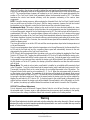
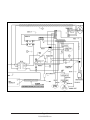
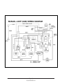
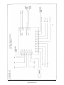
SCS300T Control Board Wiring Diagram
59
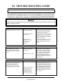
CHAPTER Xl:
TROUBLE SHOOTING GUIDE
61
APPENDIXES
J2001T Pellet Stove
A
Cast Legs J2067T & Gold Legs J2068T
B
Combustion Fan Assembly
C
Exhaust Blower Assembly
D
Auger Motor & Bracket
E
KWM Relay Kit #03DAA
F
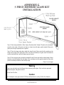
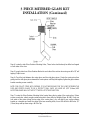
3 Piece Mitered Glass Kit
G
J1000 Crossflow Fan #07EEG
H
Exhaust Blower Assembly Model J1000
I
Warnings
J
SERVICE RECORD AND NOTES
OPPOSITE INSIDE BACK COVER
WARRANTY REGISTRATION CARD
INSIDE BACK COVER
JAMESTOWN LIMITED FIVE YEAR WARRANTY POLICY
Page iii
1998-2006 Edition
BACK COVER
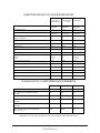
JAMESTOWN PELLET STOVES SPECIFICATIONS
J1000B
Without Leg,
Pedestal Or Riser
J2000T
With Standard
Pedestal
J2001T
Without Riser
Standard Color
METALLIC
CHARCOAL
METALLIC
CHARCOAL
METALLIC
CHARCOAL
Maximum BTU Input
34,000
42,000
42,000
Vent Pipe Diameter
3" (76 mm) or
4" (101 mm)
3" (76 mm) or
4" (101 mm)
3" (76 mm) or
4" (101 mm)
Electrical Ampere Rating with Auto Ignition
(without Auto Ignition)
5.2
(2.2)
7.5
(2.5)
7.5
(2.5)
Vent Pipe Type
TYPE L
TYPE L
TYPE L or SS Flex
Height [in./mm.]
24/610
30/762
22.5/572
Width [in./mm.]
23/584
26/660
26/660
Depth [in./mm.]
13.5/343
24.5/622
24.5/622
Weight (lb./ kg.)
175/80
220/100
220/100
Shroud Size ( Width" X Height")
Standard
Large
29" X 42"
35" X 50"
NA
NA
29" X 41.5"
35" X 49.5"
Fuel Hopper Capacity (Lb./Kg.)
37/16.8
58/26.4
58/26.4
Minimum Fireplace Depth (in./ mm.)
NA
NA
16.5/419
Minimum Fireplace Rear Width (in./ mm.)
NA
NA
26/660
Minimum Fireplace Rear Height (in./ mm.)
NA
NA
22.5/572
Maximum Vertical Vent Length (Ft./M.)
35/10.5
35/10.5
35/10.5
Maximum Horizontal Vent Length (Ft./M.)
25/7.5
25/7.5
25/7.5
CLEARANCES TO COMBUSTIBLES REQUIREMENTS
J1000B
J2000T
J2001T
Stove Back To Back Wall (in./mm.)
1/25
1/25
1/25
Stove Side Panel To Standard Side Wall
(in./mm.)
3/76
3/76
3/76
Stove Side Panel To Alcove Side Wall (in./mm.)
5/127
5/127
5/127
Stove Rear Corners To Standard Side Wall
(in./mm.)
1/25
1/25
1/25
Stove Rear Corners To Alcove Side Wall
(in./mm.)
5/127
5/127
5/127
Stove Front To Carpet Or Any Combustible
Floor (in./mm.)
6/152
6/152
6/152
Manufacturer reserves the right to change all or some of the specifications without prior written notice.
Page iv
1998-2006 Edition
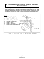
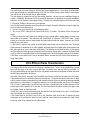
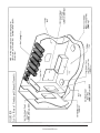
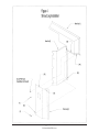
Notes:
Drawing is not to Scale or Proportion.
*
Ash Pan (6) and Ash Pan Latch (7)
are on models J2000 AND J2001T ONLY.
REFERENCES TO THE ASH PAN AND THE ASH PAN
LATCH THROUGHOUT THIS MANUAL REFER TO
MODELS J2000 AND J2001T ONLY.
MODEL J1000 DOES NOT HAVE AN ASH PAN.
Page v
1998-2006 Edition
Page vi
1998-2006 Edition
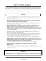
I. SAFETY FIRST ALWAYS
This Jamestown pellet burning stove or insert was designed to provide many years of trouble free enjoyment in
your home. It is up to you, however, to learn how to safely operate this new stove. All Jamestown stoves and
fireplace inserts must be installed correctly to assure safe and efficient operation. We have no control over the
installation or operation of your stove or insert, we grant no warranty, implied or stated, for the installation or
maintenance and assumes no responsibility for any consequential damage(s).
Caution
1. (a) DO NOT ATTEMPT TO INSTALL THIS PELLET STOVE YOURSELF. HAVE THE JAMESTOWN
DEALER OR A CERTIFIED TECHNICIAN INSTALL THE PELLET STOVE TO MEET ALL LOCAL AND
NATIONAL SAFETY STANDARDS.
(b) IN CANADA INSTALL IN ACCORDANCE WITH CAN/CSA-B365, INSTALLATION CODE FOR
SOLID-FUEL-BURNING APPLIANCES AND EQUIPMENT.
(c) IN THE USA FOLLOW NFPA 211, STANDARD FOR CHIMNEYS, FIREPLACES, VENTS, AND
SOLID FUEL BURNING APPLIANCES.
2. IMPROPER INSTALLATION, ADJUSTMENT, ALTERATION, SERVICE OR MAINTENANCE MAY
RESULT IN PROPERTY DAMAGE, BODILY INJURY OR EVEN DEATH AND WILL VOID ALL
WARRANTY OR ANY OTHER CLAIMS MADE TOWARDS THE MANUFACTURER. FOR ASSISTANCE
OR ADDITIONAL INFORMATION, CONTACT YOUR JAMESTOWN DEALER, CERTIFIED INSTALLER
OR LOCAL SERVICE AGENCY.
3. DO NOT STORE OR USE GASOLINE OR OTHER FLAMMABLE VAPORS OR LIQUIDS IN THE
VICINITY OF THIS OR ANY OTHER APPLIANCE.
4. NEVER USE GASOLINE, GASOLINE-TYPE LANTERN FUEL, KEROSENE, CHARCOAL LIGHTER
FLUID OR SIMILAR LIQUIDS TO START OR FRESHEN UP A FIRE IN THIS HEATER. KEEP ALL
SUCH LIQUIDS WELL AWAY FROM THE HEATER WHILE IT IS IN USE.
5. (a) DO NOT INSTALL A FLUE DAMPER IN THE EXHAUST VENTING SYSTEM OF THIS UNIT.
(b) WHERE PASSAGE THROUGH A WALL, OR PARTITION OF COMBUSTIBLE CONSTRUCTION IS
DESIRED, THE INSTALLATION SHALL CONFORM TO CAN/CSA-B365, INSTALLATION CODE FOR
SOLID-FUEL BURNING APPLIANCES AND EQUIPMENT IN CANADA.
6. DO NOT CONNECT THIS UNIT TO A CHIMNEY FLUE SERVING ANOTHER APPLIANCE.
7. INSTALL VENT SYSTEM COMPONENTS AT CLEARANCES SPECIFIED BY THE VENT
MANUFACTURER.
8. IF INSTALLING IN A MANUFACTURED HOME, THE STRUCTURAL INTEGRITY OF THE
MANUFACTURED HOME FLOOR, WALL, CEILING AND ROOF MUST BE MAINTAINED. REFER TO
PAGE 4 OF THIS MANUAL.
Warning
IF INSTALLING THIS UNIT IN A MANUFACTURED HOME, DO NOT INSTALL IN SLEEPING ROOM.
Page 1
1998-2006 Edition
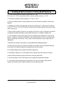
Safety Notices
1. This pellet stove should be inspected before use and at least annually by a qualified service person. More
frequent cleaning of ash collection areas and compartments is required due to the nature of fuel being used.
It is imperative that control compartments, combustion areas and circulation air passageways of the appliance
be kept clean.
2. If this stove is not installed properly, a house fire may result. For your safety, follow the installation
directions. Contact local building or fire officials about restrictions and installation inspection requirements in
your area.
3. Contact your local building officials for appropriate permits and information on possible restrictions or
requirements on installation in your area.
4. Read this Installation and Operating Instructions Manual thoroughly before attempting to install and/or burn
your new stove.
5. Always follow the lighting instructions in this owner's manual. Shortcuts of any kind can be dangerous!
6. Follow the installation and maintenance instructions outlined in this Owner's Manual exactly.
7. Burn 1/4" diameter (6.35mm) pelletized bio-mass fuel which meets or exceeds APFI Standards only. Poor
quality fuel will directly and adversely affect the efficiency and cleanliness of this stove. The local Jamestown
Dealer can help you make the proper fuel choice in your area.
8. Always keep flammable liquids away from this stove.
9. SOOT AND FLY ASH: FORMATION AND NEED FOR REMOVAL:The products of combustion will contain
small particles of fly ash. The fly ash will collect in the exhaust venting system and restrict the flow of the flue
gases. Incomplete combustion, which occurs during startup and shutdown or due to incorrect operation of the
room heater, will lead to some soot formation that will collect in the exhaust venting system. The exhaust
venting system should be inspected at least once every year to determine if cleaning is necessary. WARNING:
When wood is burned slowly, it produces tar and other organic vapors and these combine with expelled
moisture to form creosote. The creosote vapors condense in the relatively cool chimney flue associated with
a slow burning fire. As a result, creosote residue accumulates on the flue lining. When ignited, this creosote
can result in an extremely hot fire.
10. When removing fly ash accumulations from the stove, always place them in a metal container with a tight
fitting lid. The closed container must be placed on a non-combustible surface, well away from all combustible
materials, pending final disposal. If the ashes are disposed of by burial in soil or otherwise locally dispersed,
they should be retained in the closed container until all cinders have thoroughly cooled. Important: Keep firing
and de-ashing doors closed and maintain all seals in good condition.
11. The power supply cord must be routed away from hot or sharp surfaces and objects plugged into a
grounded three pronged outlet meeting all applicable local and national electrical safety codes.
12. Never place a combustible object on the stove top or trivet.
13. Failure to follow the instructions in this manual may result in property damage, bodily injury or even death.
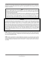
Please Note
Inattention to these points or other violations of any kind will constitute sufficient cause for the voiding of all
applicable warranty and will also void all claims made towards the Manufacturer.
WARNING: DO NOT STORE ANYTHING IN THE SPACE BENEATH YOUR STOVE.
Page 2
1998-2006 Edition
II. INSTALLATION REQUIREMENTS
General Requirements
1. The floor protection pad referred to throughout this manual must be safety listed, unless it is constructed
from a non-combustible material.
2. Outside air must be supplied for combustion. A 1-5/8" (41mm) minimum interior diameter metallic 0.16”
(4mm) thick wall air supply hose must be installed between the combustion air intake stub (located on the
back panel) and the outside of the home to provide outside combustion air. Failure to do so may cause
exhaust gases and soot particles to leak into the home under certain conditions. Any claims made for
damages caused by the use of interior room air for combustion will be voided.
3. Any installation incorporating an existing chimney must include a re-lining of the existing chimney. All
existing chimneys must be relined using flexible galvanized or stainless steel vent pipe.
4. Installation of the J2001T Insert in a wood framed chase or other wood framed enclosure that does not
have an existing chimney system requires the use of rigid L-type pellet vent pipe. A minimum 3" (76mm)
clearance to combustible materials must be maintained from the outer surface of the L-type vent pipe used.
5. Galvanized or stainless steel flex vent pipe is required for installation of the J2001T Insert in
prefabricated wood-burning fireplaces with an existing chimney system.
6. Caution should be exercised when installing the J2001T in an old masonry fireplace. The flue tile may
be weak, broken or have large globs of mortar obstructing the exhaust flow. It is important to clean the
chimney and fireplace cavities thoroughly and completely before installing the insert. No short cuts should
be taken in cleaning the fireplace cavity before installing the fireplace insert. If the fireplace is not cleaned
property, the convection blower will pick up the existing soot and fly ash and blow it into the home causing
soot damage to the walls, draperies, carpeting and such.
7. A 12" (305mm) minimum distance must be maintained at all times between the outlet of the exhaust rain
cap and the inlet opening of the air intake rain cap.
8. The required exhaust pipe diameter depends on the distance from the stove or insert to the termination
point of the vent pipe (chimney cap) and the number of elbows along the length of the vent system. As a
rule, if the total vent pipe length is 11 feet (3.4m) or more use 4" (102mm) diameter pipe. If the total length
is less than 11 feet (3.4m), use 3" (76mm) diameter pipe. If more than one 90 degree elbow is to be used,
increase the vent pipe diameter to 4" (102mm). No more than a total of 180 degrees of bends should be
used throughout the length of the vent system.
9. When assembling the chimney system, ensure that all pipe connections are sealed completely using
RTV high temperature silicone and high temperature foil tape. All connections, including twist-lock type
connections, must be sealed using RTV. If any of the connections are not sealed property, carbon monoxide
and ash will filter through these connections into the fireplace cavity, be picked up by the convection blower
and dispersed throughout the house. Any claims made for damages caused by improperly sealed vent pipe
joints will be voided.
10. Installation of a clean-out "T" at the first elbow of the vent pipe system, if possible, is recommended for
ease of cleaning and maintaining your chimney. Annual inspection and cleaning of the vent system is an
absolute requirement.
11. Use of "B" vent pipe (gas appliance vent pipe) with any Jamestown pellet stove or insert is strictly
prohibited.
Page 3
1998-2006 Edition
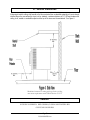
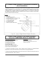
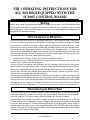
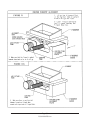
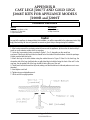
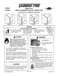
Manufactured (Mobile) Home Installation Requirements
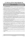
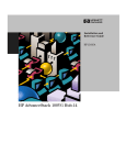
1. All manufactured home installations require the unit to be secured, permanently, to the floor or fireplace
hearth. See Figure A1, below. Units installed on top of sheet steel or cast iron legs will require an alternate
fastening method. A specific Jamestown Mobile Home Attachment kit is available through the local
Jamestown dealer. Please contact your local Jamestown dealer.
2. If installing in a manufactured home, the structural integrity of the manufactured home floor, wall, ceiling
and roof must be maintained.
3. Outside air must be supplied for combustion. A 1-5/8" (41mm) minimum interior diameter air supply
hose must be installed between the combustion air intake stub (located on the back panel) and the outside
of the home to provide outside combustion air. Failure to do so may cause exhaust gases and soot particles
to leak into the home under certain conditions. Any claims made for damages caused by the use of interior
room air for combustion will be voided.
4. Do not install this unit in a sleeping room.
5. The appliance must be grounded in accordance with local codes or, in the absence of local codes, with
the current National Electrical Code ANSI/NFPA 70 in the USA or the current CSA C22.1 Canadian Electrical
Code. Use copper lugs to mechanically fasten a #8 grounding wire to the stove body or pedestal and the
steel frame of the manufactured home. Should you have questions, please consult the local building code
enforcing official in your area.
SECURE TO FLOOR
Must meet requirements under UL1482 Section 52.2.3 e.
Page 4
1998-2006 Edition
III. CLEARANCES TO COMBUSTIBLES
REQUIREMENTS
for J1000B, J2000T
Clearances to combustible materials must be strictly adhered to. Compromising these clearances will lead to
severe fire hazards and will result in a house fire. If ever in doubt about the classification of a building material
located near this pellet stove, contact the Jamestown dealer or the local fire Marshall to determine if that
particular material has been classified as a non-combustible material. Failure to adhere to the clearances
requirements will void all applicable warranty and/or claims against the manufacturer..
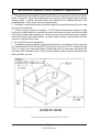
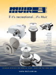
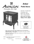
A. Floor Protection Requirement
All Jamestown free-standing stoves must be installed on a non-combustible floor pad or
a masonry hearth. The hearth or floor pad must extend the full width and depth of the
stove and also extend a minimum of 6" (152mm) from the front of the stove face. Please
refer to Figure 1. The standard pedestal base, available through a Jamestown dealer,
for the J1000B and J2000T model stoves meets this floor protection requirement.
B. Installing on Carpet or Other Combustible Floor Surfaces
Installation of a Freestanding Stove on carpeting or other combustible floor surfaces requires the installation of a Floor Protection
Pad in addition to a pedestal or legs. The standard pedestal bases (Bases #J1065B and J1065T-1 for Model J1000B and Base
#J2030 for Model J2000T) qualify as standard floor protection pads and may be used when installing the Freestanding Stoves on
carpeting or combustible floor surfaces.
J1000B RISER REQUIREMENT
When installing the J1000B pellet stove as a hearth model without pedestal or legs, a riser (part # J1065B) must
be securely attached to the stove bottom in order to provide adequate clearance to the floor surface under the
stove. This riser must be used even when the floor under the stove is constructed of a non-combustible material.
Page 5
1998-2006 Edition
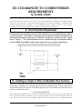
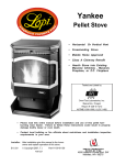
C. Alcove Installation
If installing a free-standing stove inside
an alcove, please refer to Figure 2. A
minimum of 5" (127mm) must be
maintained from the side panel of the
stove to any combustible wall extending
past the front face of the stove. A
minimum of 3" (76mm) must be
maintained from the side panel of the
stove to any combustible wall which is
to the side of the stove and does not
extend past the front face of the stove.
A minimum of 1" (25mm) must be
maintained from the rear most part of
the stove to any combustible material
or wall.
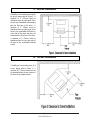
D. Corner Installation
If installing a free-standing stove in a
corner, please refer to Figure 3. A
minimum of 1" (25mm) clearance must
be maintained from the rear corners of
the stove to any adjacent walls.
Page 6
1998-2006 Edition
E. Vertical Clearances
If planning to install a ceiling, shelf, mantle or the like constructed from combustible materials or if one is already
installed above the area where the stove is to be situated, a minimum distance of 18" (457mm) between the
ceiling, shelf, mantle or combustible object and the top of the stove must be maintained. See Figure 4.
Minimum clearances to venting and top of unit to ceiling
must meet requirements under UL1482 Section 52.2.3 f.
Caution
HOT WHILE IN OPERATION. KEEP CHILDREN, CLOTHING AND FURNITURE AWAY.
CONTACT MAY CAUSE BURNS.
Page 7
1998-2006 Edition
Page 8
1998-2006 Edition
IV. CLEARANCES TO COMBUSTIBLES
REQUIREMENTS
J2001T INSERT
The J2001T fireplace insert can be installed inside two types of enclosures:
A. A pre-manufactured wood burning fireplace, either masonry or sheet metal, that has not been
modified in any way that may reduce the original fire protection capability of that fireplace.
B. A wood framed enclosure such as a chase or other form of wooden enclosure with the appropriate
clearances as specified below.
Important
Install in accordance with CAN/CSA-B365 Installation Code for Solid Burning Appliances and Equipment.
A. Installation In A Pre-Manufactured Wood Burning Fireplace (See Figure 6)
1. If this Insert is installed in a pre-manufactured wood burning fireplace, the minimum clearances to
combustibles affect only the portion of this Insert which protrudes into the room from the front face of
the existing fireplace.
2. This type of installation must include an approved non-combustible floor protection pad equivalent to
a 3/8" (9.5mm) millboard (Backer Board™) minimum or a masonry hearth which extends a minimum
of 6" (152mm) from the front face of the Insert (where the door gasket touches when closed) and
5" (127mm) from either side. See Figure 6.
3. The minimum distance from the top of the Insert (trivet surface) to the bottom of a mantel, shelf, or
other combustible overhang extending over this unit is 18" (457mm). See Figure 7.
4. The minimum distance from this insert's side panels to any combustible material or surface adjacent
to the side panel must be 3" (76mm).
B. Installation In A Wood Framed Enclosure/Chase (See Figure 6)
1. Minimum clearances to combustibles affects all parts of this Insert.
2. The installation must include, as a minimum, an approved non-combustible floor protection pad
equivalent to a 3/8" (9.5mm) millboard (Backer Board™) or a masonry hearth which extends a
minimum of 6" (152mm) from the front face of the Insert (where the door gasket touches when
closed), 5" (127mm) from either side and 1" (25mm) from the back panel. See Figure 5.
3. The minimum distance from the top of the Insert (trivet surface) to the bottom of a mantel, shelf, or
other combustible overhang extending over this unit is 18” (457mm).
4. The minimum distance from the fuel hopper top to the ceiling inside the wood framed enclosure must
be 36" (914mm).
5. The minimum distance from this insert's side panels to any combustible material or surface adjacent
to the side panel must be 5" (127mm).
C. Floor Protection Pad for all Installations (See Figure 5 & 6)
All installations of the J2001T Insert must include an approved non-combustible floor protection pad equivalent to
a 3/8" (9.5mm) millboard minimum or a masonry hearth which extends a minimum of 6" (152mm) from the front
face of the Insert (where the door gasket touches when closed) and 5" (127mm) from either side. If installing this
Insert on a combustible floor (constructed of wood framing, wafer board, particle board or the like) the floor
protection pad must also extend 1" (25mm) beyond the back panel of the stove. The floor protection pad selected
(unless installing on a masonry hearth) must be safety approved. Consult local building or fire code enforcement
officials before selecting the floor protection pad material.
Page 9
1998-2006 Edition
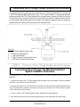
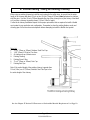
D. Clearances to Combustible Materials Requirements
for J2001T Insert - Vertical Venting Using an Existing Chimney
When using an existing chimney to install the vent system for the pellet stove, be sure to line the entire length
of the chimney with three (3) inch or four (4) inch (76mm or 102mm) listed galvanized or stainless steel flex
pipe. Use four (4) inch diameter (102mm) flex pipe if the chimney has a prior history of bad draft or if you
have a chimney exceeding eleven (11) feet (3.4m) in height.
Contact local chimney installation experts for the proper procedures that are required to install a flexible vent
system for your particular vent configuration. Remember to clean the existing fireplace cavity and chimney
pipe of all soot and creosote deposits before attempting to install the flexible vent system.
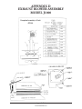
PARTS LIST
1. 3" or 4" (76mm or 102mm) Stainless Steel Flex Pipe
2. 1-5/8" ID (41mm) Rigid or Flex Hose
3. Air Intake end cap / rodent screen
4. Existing Flashing
5. Existing Storm Collar
6. 3" or 4" (76mm or 102mm) Rain Cap
7. Existing Vent Pipe.
Note: If the vertical length of the existing chimney is greater than 11 feet (3.4m),
use 4" (102mm) Stainless Steel Flex Pipe to line the entire length of the chimney.
Installation in Existing Fireplace
FIGURE 12: Relining an existing chimney
Clearance to Shelf of Mantle
Page 10
1998-2006 Edition
V. GENERAL VENT SYSTEM INFORMATION
Warning
Only use vent components that are listed for a National product safety certification agency. All venting components
used must be listed “PL” Vent or in existing chimney lined with listed solid fuel burning chimney lines (UL1482 and
ASTM E 1509 standards). Use of inferior components can lead to fire and carbon monoxide hazards and will void
all applicable warranty and any claims made towards the manufacturer.
1. All existing chimneys larger than TEN (10) inches (254mm) in diameter or exceeding eleven (11) feet (3.4m) in
total length must be relined through their entire lengths using either a three (3) inch or four (4) inch (76mm or
102mm) stainless steel or galvanized flex pipe with a spark arrester/rain cap at the termination point.
2. Any chimney exceeding eleven (11) feet (3.4m) in height must be relined using a four (4) inch (102mm)
stainless steel or galvanized flex pipe with a spark arrestor/rain cap at the termination point.
3. Maximum vertical vent system length is 35 feet (10.7m). Maximum horizontal vent system length is 10
feet (3m).
4. When using listed "L" type vent pipes and components, allow a minimum of twelve (12) inches (305mm)
between the exhaust termination and the outside air intake tube termination. Failure to maintain the required 12"
(305mm) separation may cause some exhaust gases to draw into the system resulting in an inefficient burn (lazy
fire). When installing the Jamestown J3020A or the J3030B vent systems, however, it is not necessary to maintain
this 12" (305mm) distance between the exhaust termination and the outside air intake tube-termination. These
two vent kits have been tested and certified to be installed in variation to this 12" (305mm) separation requirement.
5. "L" Type pellet vent may be installed directly through a combustible wall, ceiling, or roof, using a listed wall
thimble, fire stop, or roof flashing. Clearance using a listed wall thimble will be a minimum of 1 1/2" (38mm) to any
combustible material; using a ceiling fire stop or roof flashing requires 3" (76mm) minimum clearance to any
combustible.
6. Check the spark arrestor or rain cap and ensure that the screens or louvers do not restrict exhaust flow.
7. Check the spark arrestor/rain cap on a regular basis to see if it is plugged with soot or flying debris such
as leaves.
Using an Existing Chimney to Vent a Pellet Stove
When using an existing chimney to install the vent system for this pellet stove, be sure to line the entire length
of the chimney with three (3) inch or four (4) inch (76mm or 102mm) listed galvanized or stainless steel flexible
pipe if the chimney has a prior history of bad draft or if the chimney exceeds eleven (11) feet (3.4m) in height.
Installations Requiring A Complete New Chimney System
1. All complete new chimney systems must use listed L-type pellet vent pipe for all components of the vent
system. Use three (3) inch (76mm) diameter pipe when the total chimney length is under eleven (11) feet (3.4m)
and four (4) inch (102mm) diameter pipe when the total chimney length is over eleven (11) feet (3.4m).
2. The exit terminal must be located not less than 60" (1.5m) from any opening through which combustion
products could enter the building (i.e. doors, windows, vents), nor less than 24" (610mm) to an adjacent
building and not less than 7" (178mm) above grade when located adjacent to public walkways. It must be
so arranged that flue gases are not directed so as to jeopardize people, overheat combustible structures, or enter
a building.
3. For horizontal venting, the exhaust pipe must be terminated by employing a listed end cap or 45 degree
elbow with a rodent screen cap that prevents rain or wind from entering the exhaust pipe. For termination
above the roof line, a listed rain cap must be used.
4. Each "L" Type joint must be completely sealed using High Temperature Silicone ("RTV"), three sheet
metal screws, and High Temperature Foil Tape.
Page 11
1998-2006 Edition
Page 12
1998-2006 Edition
VI. STOVE VENT SYSTEM
CONFIGURATION OPTIONS
A variety of vent system configurations are possible for both a freestanding and fireplace insert stove. Examples of
vent system configurations include a direct through-the-wall termination, connection to an existing chimney that
previously served a wood burning stove or a wood burning fireplace and an entirely new chimney system. Read
through the descriptions of the various configurations that are possible, evaluate the final location of the stove and
decide which configuration is best suited for that particular installation. Decision should be based on such factors as
local building codes, ease of installation, cost of installation and ease of future maintenance and periodic cleaning.
If strong winds are common in the area, it is advised that two (2) 90 degree elbows be connected, in a periscope type
configuration, immediately before the spark arrester/rain cap. This will form a windbreak and allow the unit to burn at
maximum efficiency. We also suggest that if the home has vinyl siding or in areas where the wind blows often, a large
metal plate (18" x 18") (457mm x 457mm) made of 20 gauge or heavier steel be placed on the side of the house to
provide heat protection and easy cleaning; should the wind carry the exhaust against the side of the house.
Always seal all pipe connections, including "twist-lock" systems, using high temperature RTV silicone.
Descriptions of the various vent system configurations are given below.
A. Coaxial Direct Through-The-Wall Horizontal Vent Termination
(Jamestown J3020A kit)
A coaxial direct vent system is made up of two different diameter size pipes. The smaller 3" (76mm) diameter
pipe fits inside the larger 4-3/4" (121mm) diameter pipe. The 3" (76mm) diameter pipe carries the exhaust gases
out of the home and the 4-3/4" (121mm) diameter pipe carries outside combustion air into the combustion
chamber of the stove. Such a coaxial vent system requires only one 9" (229mm) diameter hole to be cut in an
exterior wall for the vent system to pass through. The Jamestown J3020A install kit is required if a coaxial directthrough-the-wall horizontal termination is desired. Coaxial vent systems for Jamestown pellet stoves cannot be
purchased separately at the local hardware store. The Jamestown J3020A install kit is available at any
Jamestown dealership.
Parts List
1. Air Intake Adapter with 5” (127mm) Air Pipe
2. 3” (76mm) Exhaust Pipe Extension
3. 5” (127mm) Wall Thimble
4. 3” (76mm) Exhaust Pipe Extension
5. Air Exhaust Rodent Screen
6. Exhaust Cap with Rodent Screen
Page 13
1998-2006 Edition
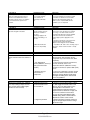
J3020A Kit Installation Instructions
This kit contains the following parts:
One Air intake adapter housing w/ 4-3/4” (121mm) air Intake pipe
One 4-3/4” (121mm) End Cap/ Rodent Screen
One 19” (483mm) length of 3” (76mm) exhaust pipe w/belled end
One Wall Thimble (2 pieces)
One 3” (76mm) Double Wall Rain Cap w/ Rodent Screen
Sixteen 1/2” #8 Hex Head self drilling & tapping Screws (Teck Screw)
Tools and other materials required:
Hand Drill with 1/4” Hex Driver
Appropriate Saw(s) to Cut 9” (229mm) Diameter Hole in Wall
Phillips Head Screw Driver
Power Drill, Phillips bit
Caulking gun with a tube of High Temperature RTV silicone
This kit contains all the materials, except 8 screws, that are needed to secure the wall thimble to the wall.
The type of screws needed depends on the type of wall material. The recommended type of screw for each
type of wall material is listed below:
Wall Material
Wood
Sheet Metal
Masonry
Dry Wall
Recommended Screw Type
3/4” #6 Wood Screw
1/2” #6 Sheet Metal Screw
1-1/2” Molly Bolts
1” #6 sheet metal screws with plastic anchors
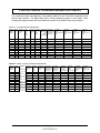
TABLE 1: Location Of Center Of 9" Hole In The Wall
MODEL
LEFT
From
Center
Line
J1000B w/
J1000B w/
J1000B
J2000T
Sheet Metal
Legs
Cast Legs
w/ Pedestal
W/ Pedestal w/ Cast Legs
1/8"
(3mm)
1/8"
(3mm)
1/8"
(3mm)
1-5/8"
(41mm)
1-5/8"
(41mm)
1-5/8"
(41mm)
10-1/2"
(267mm)
8-7/8"
(225mm)
13-1/2"
(343mm)
11-7/8"
(302mm)
4-1/2" (114mm)
[if using a riser add
riser height]
UP From
8-3/4" (222mm)
Floor Board [add 1-3/4"
(45mm) if leg
balls are used]
J2000T
J2001T
LEFT: Left of the center line as shown in Figure X.
UP: Up from the top of the floor board as shown in
Figure X.
1. Determine the final position for the stove and
refer to Chapters III and IV (Clearances to
Combustible Materials Requirements) to ensure
that the final position of the stove adheres to all
the listed requirements.
2. Determine the center of the 9" (229mm) hole
that needs to be cut in the wall by using Figures
X and the table above. Example: J1000 w/ Legs.
find the center line as in Figure 2. Move 1/8"
(3mm) to the left of the center line and up 8-3/4"
(222mm) from the floor. This point is the center of
the 9" (229mm) diameter hole.
Page 14
1998-2006 Edition
3. Cut the 9" (229mm) diameter hole and
position the stove close to the installation site.
4. See Figure A on page 17. Install the inside
piece of the wall thimble (Part #5) and the
outside piece of the wall thimble (Part #6) in the
9" (229mm) diameter hole. Do not secure the
wall thimble pieces to the wall at this time.
5. Apply a liberal amount (1/4" bead) (6.5mm)
of RTV silicone around the outside surface of
the Exhaust Stub (part #1).
6. Identify the 3" (76mm) pipe with the belled
end (part # 3). Note that there are three screw
holes in the belled end. These three screw
holes should be positioned so that one of the
screw holes is towards the stove top and the
other two are towards each stove side when
installed. This position will allow easy access
when driving the securing screws.
7. Slide the belled end of part #3 over the stove
exhaust stub (Part #1) as far as it will go. Level
this part with respect to the center of the 9"
(229mm) hole in the wall and secure it in place
with one #8 x 1/2" Teck Screw through each of
the three holes on the belled end.
8. Slide the Air Intake Adapter Housing (part
# 4) over the 3" (76mm) exhaust pipe (part #3).
The adapter housing (square box on the end of
Part # 4) should envelop the air intake stub (part
# 2) as shown in Figure A Page 17. Align the
four holes on the outer bends of the square box
with the four screw holes on the back panel and
secure using one #8 x 1/2" Teck Screw through
each hole pair. If the holes in the air intake
adapter housing do not align easily with the four
holes in the stove back, flex the bends on the air
intake adapter housing so that the holes do
align and secure the air intake adapter housing
in place. Seal all open corners of the air intake
housing box using RTV silicone.
Page 15
1998-2006 Edition
9. Slide the Stove into its final position while guiding the
installed vent system through the wall thimble. Refer to
Chapters III and IV (Clearances to Combustible Materials
Requirements) to ensure that the final position of the stove
adheres to all the listed requirements.
10. Check for wall thimble fit around the 4-3/4" (121mm) pipe,
adjust as necessary and secure the wall thimble pieces to the
wall using eight screws designed for your wall material type.
11. Fill any gaps between the wall thimble and the 4-3/4"
(121mm) pipe with RTV silicone.
12. Slide the 4-3/4" (121mm) End Cap/Rodent Screen (part #
7) so that the sleeve fits inside the 4-3/4" (121mm) pipe and the
3" (76mm) exhaust pipe slides through the 3" hole at the center
of the End Cap. Secure the cap in place using one #8 x 1/2"
Teck Screw through the screw hole on the side of the 4-3/4"
(121mm) pipe.
13. Slide the 3" (76mm) Double Wall Rain Cap ( part # 8) over
the end of the 3" (76mm) exhaust pipe with the open end of the
cap facing downward at an angle, as shown in Figure A.
Secure the Rain Cap to the 3" (76mm) exhaust tube using three
#8 x 1/2" Teck Screws. Space the screws evenly around the 3"
(76mm) tube.
Installation of the "through the wall exhaust kit" is now complete.
Check the entire exhaust system to ensure that there are no
exhaust gas leaks.
Where passage through a wall, or partition of
combustible construction is desired, the installation
shall conform to CAN/CSA-B365 Installation Code for
Solid Fuel Burning Appliances and Equipment in
Canada.
Page 16
1998-2006 Edition
Page 17
1998-2006 Edition
Parts List
1. Exhaust Stub
2. Air Intake Stub
3. 19” (485mm) long 3” (76mm) Diameter Exhaust Pipe
4. Air Intake Adapter Housing with 4-3/4” (121mm) Pipe
5. Wall Thimble Inner Piece (painted face)
6. Wall Thimble Outer Piece
7. 4-3/4” (121mm) End Cap/Rodent Screen
8. 3” (76mm) Rain Cap with Rodent Screen
9. Air Intake Adapter Mounting Holes
B. Conventional Direct Through-The-Wall Horizontal Vent Termination
A conventional direct vent system must be constructed from a 3" (76mm) diameter listed "PL" type pipe and
1-5/8" (41mm) diameter rigid or flexible hose or pipe. The 3" (76mm) diameter "L" type pipe transports the
exhaust gases while the 1-5/8" (41mm) diameter hose or pipe transports combustion air from the outside of
the home to the stove. This type of vent system is easy to install and maintain. However, two holes must be
cut in the exterior wall for this system to pass through. All components required for this vent system are
available at all local hardware stores and at the local Jamestown Dealer.
Parts List
1. 1-5/8” (41mm) Diameter Hose or Pipe
2. 3” (76mm) PL-Type Vent Pipe
3. 3” (76mm) Wall Thimble
4. 3” (76mm) Exhaust Cap with Rodent Screen
5. 1-5/8” (41mm) Air Intake Rodent Screen
Conventional Direct Through-The-Wall Horizontal Vent
System Installation Instructions
It is necessary to cut a 7" (178mm) and a 1-3/4" (45mm) diameter hole in the wall as passages for the vent pipe and the air
intake tube.
1. Determine the location of the 7" (178mm) diameter hole by referring to the section labeled "J3020A kit Installation
Instructions" in this manual. Mark the hole location.
2. Determine the location of the 1-3/4" (45mm) hole. Determine this location based on the tube material that you are
using. Remember that the openings in the exhaust vent cap must be a minimum of 12" (305mm) from the openings
in the air intake rodent screen openings.
3. Cut the 7" and the 1-3/4" (178mm and 45mm) holes in the wall using an appropriate saw.
4. Move the stove away from the wall to provide enough clearance for the entire length of the exhaust pipe.
Page 18
1998-2006 Edition
5. Apply a liberal bead of RTV silicone around the perimeter of the exhaust stub.
6. Slide the female end of the 3" (76mm) L-type vent pipe over the exhaust stub as far as it will go. Secure the pipe
in place using three #8 x 1” self drilling and tapping screws evenly spaced around the perimeter of the 3" (76mm) pipe.
7. Slide one part of the wall thimble over the far end of the 3" (76mm) pipe. Make sure that the round collar on the
wall thimble is towards the hole in the wall.
8. Carefully slide the stove into its final position while guiding the 3" (76mm) pipe through the 7" (178mm) hole in the
wall. Remember to maintain all the required clearances to the walls and any combustible objects adjacent to the stove.
Refer to Chapter III and IV of this manual.
9. Center the wall thimble part in the 7" (178mm) hole and secure to the wall using four screws appropriate for the
existing wall type.
10. Seal the gap between the wall thimble and the 3" (76mm) pipe using RTV silicone.
11. From the outside of the home, slide the outside part of the wall thimble over the end of the 3" (76mm) pipe. Secure
the wall thimble to the exterior siding of the house and seal the gap between the 3" (76mm) pipe and the wall thimble
with RTV silicone. Use the appropriate screw type for the type of siding on the house.
12. Apply a bead of RTV silicone to the end of the 3" (76mm) pipe.
13. Affix the exhaust termination cap to the end of the 3" (76mm) pipe and secure in place with three #8 x 1" self
drilling and tapping screws, spaced evenly around the perimeter of the 3" (76mm) pipe.
14. Use the same method to attach the 1-5/8" (41mm) air intake rigid tube or flexible hose to the air intake stub.
However, it is not necessary to use 3 screws to secure the air intake tube/hose to the air intake stub.
15. Use the appropriate elbows or other fittings to channel the air intake tube/hose to the location of the 1-3/4” (45mm)
hole in the wall. Trim the air intake tube approximately flush with the outside of the wall. Remember, installation of an
end cap with a rodent screen or louvers is required to prevent birds and/or rodents from entering the air intake tube.
16. Seal the gap between the air intake tube and the 1-3/4" (45mm) hole in the wall using an appropriate sealant
material for the existing wall type.
Page 19
1998-2006 Edition
C. Coaxial Through-The-Wall 45° Horizontal Vent Termination
(Corner Installations)
If installing the pellet stove in a corner and a coaxial horizontal vent system is desired, the Jamestown
J3030A 45 Degree Vent Kit (for model J3000A) or the Jamestown J3030B 45 Degree Vent Kit (for models
J1000B and J2000T) is required in addition to the Jamestown J3020A kit. The J3030A kit or J3030B kit and
the J3020A kit, when combined, contain all the materials that are necessary to complete a coaxial throughthe-wall 45 degree horizontal vent system.
Parts List
1. 45º Adapter
2. 3” (76mm) Diameter 45º “L”
3. Air Intake Adapter with 5” (127mm) Air Pipe
4. 3” (76mm) Exhaust Pipe Extension
5. 5” (127mm) Wall Thimble
6. Air Intake Wall Thimble
7. Exhaust Cap with Rodent Screen
Coaxial Through-The-Wall 45° Vent System Installation
Instructions JAMESTOWN J3030A and J3030B KITS
This kit contains the following parts:
One 45 degree housing extension (J3030B kit only)
One 3" (76mm) 45 degree elbow
One 45 degree elbow housing adapter
One 3" (76mm) exhaust pipe extension
One 4-3/4" (121mm) coupler
One 4-3/4" (121mm) air intake pipe extension
Twenty four #8 x 1/2" self drilling and tapping screws
Six #8 x 1/2" Phillips screws with matching nuts
Tools Required:
Electric drill with 1/4" hex driver
Saw to cut a 9" (229mm) diameter Hole in the wall
Phillips head screw driver
1. Determine the final position of the stove. Refer to Chapters III and IV (Clearances to Combustible Materials
Requirements) to ensure that the final position of the stove adheres to all the listed requirements.
2. Determine the vertical distance between the floor and the center of the 9" (229mm) hole that you will need to cut
in the wall by using Figure X, Table 1 on Page 14.
Page 20
1998-2006 Edition
3. Determine the horizontal location of the center of the 9" (229mm) hole by moving the stove to its final position,
attaching the 3" (76mm) 45 degree elbow and the 3" (76mm) exhaust pipe with belled end to the exhaust stub of the
stove. Mark the hole location on the wall.
4. Cut the 9" (229mm) diameter hole and position the stove close to the installation site. Remember to maintain all
the required clearances to the walls and any combustible objects adjacent to the stove. Refer to Chapter III and IV of
this manual.
5. See Figure B. Apply a liberal amount of RTV silicone around the perimeter of the non-belled end of the 45 degree
3" (76mm) elbow (part # 6). Slide the belled end of the 3" (76mm) exhaust pipe (Part # 7) over the non-belled end of
the 45 degree 3" (76mm) elbow ( Part # 6) and secure together using three (3) #8 Teck Screws spaced equally around
the perimeter.
6. Apply a liberal amount of RTV silicone to the outside surface of the Exhaust Stub (part #1). Install the exhaust pipe
and 45 degree elbow assembly onto the stove exhaust stub by sliding the belled end of the 45 degree elbow (Part # 6)
over the stove exhaust stub (Part #1) as far as it will go. Orient the 3" (76mm) exhaust pipe properly with respect to the
9" (229mm) hole in the wall. Secure this assembly to the exhaust stub using three (3) #8 Teck Screws spaced equally
around the perimeter. The attached assembly must be in a horizontal position and parallel to the floor.
7. Determine the total length of 3" (76mm) exhaust pipe required to exit the wall. The exhaust termination cap must be
12 inches (305mm) away from the outside surface of the wall. If an additional 3" (76mm) exhaust pipe extension (Part
# 7) is required to reach this length, cut the extra part # 7 to the required length using a hacksaw and attach to the 3"
(76mm) exhaust pipe, already attached to the 45 degree elbow, after first applying a bead of RTV silicone to the nonbelled end of the 3" (76mm) exhaust pipe that is already attached to the stove. Note: If the second 3" (76mm) exhaust
pipe is required, an extra 4-3/4" (121mm) air intake pipe extension is also required. Cut the 4-3/4" (121mm) extension
pipe (supplied with the J3030A and J3030B kits) to the same length as the second 3" (76mm) exhaust pipe. Do not
attach this 4-3/4" (121mm) extension pipe at this time.
8. FOR MODELS J1000B AND J2000T USING THE J3030B KIT: Slide the air intake adapter extension (part # 4) over
the 3" (76mm) pipe assembly attached to the stove. Align the open slots in the 45 degree housing extension with the
mounting holes (#3). Secure the air intake adapter extension to the back panel using #8 x 1/2" Teck screws. For Model
J3000A, the air intake adapter extension (part #4) is not required and is not shipped with J3030A kit.
9. Note that the 45 degree elbow housing is not a symmetrical part. It must be oriented as shown in the diagram
below to provide enough room for the 45 degree 3" (76mm) elbow. Align the open slots in Part #4 with the open slots
in Part # 5. If this position does not provide enough room for the 45 degree 3" (76mm) elbow to fit inside part #5,
remove part #5 and rotate to align the open slots on the opposite with the open slots on part #4. Slide the 45 degree
elbow housing (Part # 5) over the 3" (76mm) pipe assembly. Make sure that Part # 5 is oriented property towards the
direction of the 9" (229mm) hole in the wall.
10. Align the open slots in the outward bends of air intake adapter housing (part #8) with the open slots in the 45
degree elbow housing (Part # 5) as shown in Figure B. Secure these two parts together using a #8 x 1/2" Phillips
machine screws and nuts.
11. Place the inside and outside pieces of the wall thimble (Part #6 and #7) into the 9" (229mm) diameter hole. Do
not secure the wall thimble pieces to the wall at this time.
12. Connect the 4-3/4" (121mm) air intake pipe extension to the end of the 4-3/4" (121mm) air intake pipe that is
attached to part #8 using the 4-3/4" (121mm) coupling provided with the J3030A and J3030B kits. Secure these parts
together by driving three (3) #8 x 1/2" Teck Screws through each pipe and coupling connection. Space these screws
evenly around the perimeter of the pipe. Note: The Teck Screw heads protruding from the surface of the 4-3/4"
(121mm) coupler may prevent this assembly from sliding through the hole in the wall thimble. You may want to use
the Teck Screws after sliding the assembly through the wall first.
Page 21
1998-2006 Edition
13. Slide the Stove into its final position while guiding the installed vent system through the wall thimble. Refer to
Chapters III and IV (Clearances to Combustible Materials Requirements) to ensure that the final position of the stove
adheres to all the listed clearance requirements.
14. Check for wall thimble fit around the 4-3/4" (121mm) pipe, adjust as necessary and secure the wall thimble pieces
to the wall using eight screws designed for your wall material type.
15. Fill any gaps between the wall thimble and the 4-3/4" (121mm) pipe with RTV silicone.
16. Slide the 4-3/4" (121mm) End Cap/Rodent Screen (part# 11) so that the sleeve fits inside the end of the 4-3/4"
(121mm) pipe extension and the 3" (76mm) exhaust pipe slides through the 3" (76mm) hole at the center of the End
Cap. Secure the cap in place using one #8 x 1/2" Teck Screw through the side of the 4-3/4" (121mm) pipe.
17. Slide the 3" (76mm) Double Wall Rain Cap (part # 9) over the end of the 3" (76mm) exhaust pipe with the open
end of the cap facing downward at an angle, as shown in Figure B. Secure the Rain Cap to the 3" (76mm) exhaust
tube using three #8 x 1/2" Teck Screws. Space the screws evenly around the 3" (76mm) tube.
Installation of the Coaxial Through-The-Wall 45 Degree Vent System is now complete. Check the entire exhaust
system to ensure that there are no exhaust gas leaks.
Page 22
1998-2006 Edition
Page 23
1998-2006 Edition
Parts List
1. Exhaust Stub
2. Air Intake Stub
3. Air Intake Adapter Extension Mounting Holes
4. Air Intake Adapter Extension
5. 45º Elbow Housing
6. 3” (76mm) Diameter 45º Elbow
7. 19” (483mm) long 3” (76mm) Diameter Exhaust Pipe
8. Air Intake Adapter Housing with 4-3/4” (121mm) Pipe
9. Wall Thimble Inner Piece (Painted Face)
10. Wall Thimble Outer Piece
11. 4-3/4” (121mm) End Cap/Rodent Screen
12. 3” (76mm) Rain Cap with Rodent Screen
D. Conventional Through-The-Wall 45° Horizontal Termination
(Corner Installations)
If a free-standing pellet stove is installed in a corner and a Conventional Through-The-Wall vent system is
desired, connect a 45 degree L (L-type) to the 3" (76mm) exhaust stub located on the back of the stove. Rotate
the 45 degree L towards the wall along which the vertical vent system is to be run. Complete the vent system
by following the Conventional Direct Through-The-Wall Vent System installation instructions under Section B.
Parts List
1. 1-5/8” (41mm) ID Pipe, Metallic,
Minimum Thickness 0.16” (4mm)
2. 1-5/8” (41mm) ID 45º Elbow (optional)
3. 1-5/8” (41mm) ID Pipe or Hose Section
4. 1-5/8” (41mm) ID Rodent Screen
5. 3” (76mm) PL-Type 45º “L”
6. 3” (76mm) PL-Type Vent Pipe
7. 3: (76mm) Exhaust Cap with Rodent Screen
Page 24
1998-2006 Edition
E. Vertical Venting - Using An Existing Chimney
When using an existing chimney to install the vent system for the pellet stove, be sure to line the entire
length of the chimney with three (3) inch or four (4) inch (76mm or 102mm) listed galvanized or stainless
steel flex pipe. Use four (4) inch (102mm) diameter flex pipe if the chimney has a prior history of bad draft
or if you have a chimney exceeding eleven (11) feet (3.4m) in height.
Contact local chimney installation experts for the proper procedures that are required to install a flexible
vent system for your particular vent configuration. Remember to clean the existing fireplace cavity and
chimney pipe of all soot and creosote deposits before attempting to install the flexible vent system.
Parts List
1. 3" or 4" (76mm or 102mm) Stainless Steel Flex Pipe
2. 1-5/8" (41mm) ID Rigid or Flex Hose
3. Air Intake end cap / rodent screen
4. Existing Flashing
5. Existing Storm Collar
6. 3" or 4" (76mm or 102mm) Rain Cap
7. Existing Vent Pipe.
Note: If the vertical length of the existing chimney is greater than
11 feet (3.4m), use 4" (102mm) Stainless Steel Flex Pipe to line
the entire length of the chimney.
FIGURE 12: Relining an Existing Chimney
See also Chapter IV Section D “Clearances to Combustible Material Requirements” on Page 10.
Page 25
1998-2006 Edition
F. Vertical Venting Outside Roof Line
- Unit Back Parallel To Outside Wall
A vertical vent system constructed of rigid "L" type chimney pipe may be required if a horizontal termination
cannot meet the required clearances to combustible materials and/or clearances from the vent cap to any
air intake openings to the interior of the home. Follow the vent pipe manufacturer's instructions to complete
the installation of all vertical vent systems. Also see the "Conventional Direct Through-the-Wall Horizontal
Vent System" section of this manual.
Vertical Venting Outside Roof Line is desirable when the vent pipe can be run outside the home in an
unobtrusive location. This type of vent system is less labor intensive and easier to install than Vertical
Venting Inside Roof Line.
Parts List
1. 3” (76mm) Pipe PL-Type
2. 3” (76mm) Cleanout T PL-Type
3. 3” (76mm) Cleanout T Cap
4. 3” (76mm) Pipe to 4” (102mm) Pipe Adapter PL-Type
5. 4” (102mm) Pipe PL-Type
6. Wall Bracket
7. Roof Flashing
8. Exhaust Cap/Rain Cap
9. 1-5/8” (41mm) Flexible Hose or Rigid Pipe
10. 1-5/8” (41mm) Air Intake Cap/Rodent Screen
Page 26
1998-2006 Edition
G. Vertical Venting Inside Roof Line
- Unit Back Parallel To Outside Wall
A vertical vent system constructed of rigid "PL" type chimney pipe may be required if a horizontal termination
cannot provide the required clearances to combustible materials and/or clearances from the vent cap to any
air intake openings to the interior of the home cannot be adhered to. Follow the vent pipe manufacturer's
instructions to complete the installation of all vertical vent systems. Also see the "Conventional Direct
Through-the-Wall Horizontal Vent System" section of this manual.
Vertical Venting Inside Roof Line is desirable when the vent pipe cannot be run outside the home in an
unobtrusive location. This type of vent system is more labor intensive and tougher to install than Vertical
Venting Outside Roof Line.
Parts List
1. 3” (76mm) Cleanout T PL-Type
2. 3” (76mm) Pipe to 4” (102mm) Pipe Adapter PL-Type
3. 4” (102mm) Pipe PL-Type
4. Ceiling Firestop
5. Roof Flashing
6. Exhaust Cap/Rain Cap
7. 1-5/8” (41mm) Flexible Hose or Rigid Pipe
8. 1-5/8” (41mm) Air Intake Cap with Rodent Screen
Page 27
1998-2006 Edition
Page 28
1998-2006 Edition
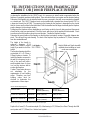
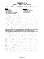
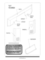
VII. INSTRUCTIONS FOR FRAMING THE
J2001T OR J1001B FIREPLACE INSERT
In planning the installation for the J2001T Insert, it is necessary to install certain components before the
fireplace is completely positioned and installed. These include the direct vent system and the electrical wiring.
Determine if the fireplace is to be installed inside the room, recessed in the wall, corner mounted or elevated
on a hearth pad. The J2001T Fireplace Insert can be installed with a standard size shroud (part # C187) or
a large size shroud (part # C188). The opening in the framing for the fireplace is dependent on the shroud
that you choose and are listed in the table below. Both the standard and the large shroud will give the fireplace
proper clearance for the exhaust venting.
Positioning of the fireplace will vary depending on such factors as which shroud is being used and the amount
of wall, fascia or trim you want exposed. Place the Insert, with shroud, at the position that is desirable. Check
to make sure that this position serves form and function. Finalize the fireplace location.
Determine the exact position of the fireplace so that the direct vent pipe is centered, if possible, between two
studs. This will avoid any extra framing. The back of the fireplace may be positioned 1" (25mm) clearance
from the combustible wall.
The height of the hearth is
optional.
However, 12-14
inches (305-356mm) is a good
height if you want to sit on the
hearth.
The fireplace framing should be
constructed of 2 x 4 (51mm x
102mm) lumber or heavier. To
install the fireplace recessed in
the wall, it is necessary to cut a
hole in the wall and build a
small insulated chase. A chase
is a box like structure built to
enclose the fireplace.
Caution: These instructions are
not substitutes for the
requirements of local building
codes. Therefore, your local
building codes must be
checked to determine the
requirements of these steps.
Height, Width and Depth standoffs
required when installing an insert
under new construction.
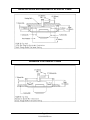
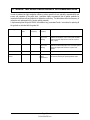
Chase Frame Opening Size
SHROUD SIZE
MIN / MAX
WIDTH (W)
INCHES (Millimeters)
HEIGHT (H)
INCHES (Millimeters)
C187 - 29" H x 41.5" W
(737mm H x 1054mm W)
MINIMUM
MAXIMUM
39.00" (991mm)
41.00" (1041mm)
27.50" (699mm)
28.00" (711mm)
C188 - 35" H x 49.5" W
(889mm H x 1257mm W)
MINIMUM
MAXIMUM
46.50" (1181mm)
48.25" (1226mm)
33.50" (851mm)
34.00" (864mm)
NOTE: These openings are measured from the top of the hearth pad.
Depth of the Frame (D): The minimum depth (D) of the framing is 13" (330mm) for a Direct Through-the-Wall
vent system and 22" (559mm) for a Vertical vent system.
Page 29
1998-2006 Edition
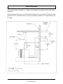
Inside the Room and Recessed in an Interior Chase
Recessed in an Exterior Chase
Page 30
1998-2006 Edition
Corner Installation
Installation requires standoffs to maintain clearances.
Page 31
1998-2006 Edition
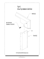
Vertical Venting
When vertical venting is required, a 3" (76mm) space between the vent pipe and the wall must be
maintained.
When locating the exhaust hole, it must be noted that the bottom of the cap must be 12" (305mm) above the
ground level. This is a minimum clearance. You must also maintain a minimum of 3" (76mm) clearance from
the ceiling.
Page 32
1998-2006 Edition
VIII. OPERATING INSTRUCTIONS FOR
ALL MODELS EQUIPPED WITH THE
SC300T CONTROL BOARD
Warning
Read this entire section thoroughly before attempting to operate your new stove. If you fail to understand some
of the operational procedures or operating characteristics, contact your local Jamestown Dealer for further
detailed explanations. Failure to heed this warning can result in serious stove component(s) damage that is not
covered under the Jamestown Warranty.
VIII.1 Introduction to Efficiencies
Pellets are delivered to the firepot by an auger/gravity feed system. The pellet fuel feed rate is controlled by
the Fuel Feed Control Knob and/or a wall thermostat. The burn rate of the pellets in the firepot is controlled
by the amount of combustion air entering the firepot, which is controlled by the Draft Control Knob. As the
pellets are burned, the hot exhaust gases are drawn past the exterior surfaces of the heat exchanger tubes
and through the side heat exchanger chambers, then blown into the vent pipe system. Cool room air is
blown by the convection blower through the heat exchanger tubes and past the exterior surfaces of the side
heat exchanger chambers. The room air absorbs heat from the hot metal surfaces and flows into the room.
The overall efficiency of the stove is determined by two factors:
1. How efficiently the pellets are burning. This is called the combustion efficiency.
2. How much room air is blowing past the heat exchanger surfaces and extracting heat from the metal
surfaces. This is called the heat transfer efficiency.
In order to achieve the maximum overall efficiency, both the combustion efficiency and the heat transfer
efficiency have to be at their maximum levels. This stove design automatically maximizes the heat transfer
efficiency by combining the fuel feed rate and the convection blower speed into one control knob. As the
fuel feed rate is increased, the convection blower speed will also increase. However; you, as the consumer,
will have to learn to maximize the combustion efficiency.
Learning to properly regulate the combustion air (draft) flow rate according to the pellet fuel feed rate is the
key to maximizing the combustion efficiency and, consequently, the fuel consumption rate and the heating
capacity of the stove. Spend a few minutes watching the instructional video and reading this manual before
attempting to burn your new stove. Pay particular attention to the sections labeled Achieving an Efficient
Burn and Efficient Flame Characteristics . If you have further questions, contact your Jamestown Dealer.
VIII.2 Achieving An Efficient Burn
Being able to burn the stove efficiently requires a proper balance between the fuel feed rate and the
combustion air/draft rate. A proper air to fuel ratio can only be established once the fire is burning steadily
and is self-sustaining. The "proper" setting is when the optimum air to fuel ratio is obtained.
All manufacturers must provide a unit which is capable of burning at sea level and also at 11,000 feet
(3353m) above sea level. Furthermore, the same unit must be able to burn fuels of variable size and quality.
At sea level, while burning 1/4" (6.35mm) diameter pellets on the #1 fuel feed setting, enough oxygen is
available to burn efficiently at (or very near) the lowest draft setting. At 11,000 (3353m) feet above sea level,
however, there simply isn't enough oxygen available in the air to burn any diameter pellet fuel at the lowest
draft setting and the lowest fuel feed setting.
Page 33
1998-2006 Edition
The same issues are relevant when the fuel feed rate is set at maximum burn. At sea level, the air/fuel ratios
at the highest settings are quite different than at 11,000 feet (3353m) because there simply is more oxygen
in a cubic foot of air at sea level than at higher altitudes.
The draft setting for a particular fuel feed rate setting, therefore, can vary from one installation location to
another. Additionally, the amount of fuel consumed will depend on the elevation, vent system installation,
pellet size, and the amount of heat output desired. Therefore, the statement that the unit will burn less than
1-1/2 pounds (0.68kg) of fuel per hour is not absolute.
Once the fire is burning steadily and all the pellets in the firepot are ignited, follow these steps to adjust the
air to fuel ratio for an efficient burn:
1. Turn the Fuel Feed Control Knob to the desired position.
2. Turn (or on J2001T, slide) the Draft Control Knob to the "1" position. The flames will turn lazy and get
longer.
3. Slowly, increase the Draft Control Knob setting to a higher setting until the smaller pieces of ember in the
firepot start to roll around. This "rolling around" characteristic is called the "POPCORN" effect. Supply
enough air so that the pieces of pellet ember are rolling around inside the firepot. However, don't let the
ember fly out of the firepot.
4. After about 1 minute at this setting, check the flame height, flame color and flame tips color. When the
proper amount of combustion air is being supplied, the flame should be a bright yellow (almost white) with
blue and purple hues close to the center of the flame. The flame tips should never be black. At the highest
fuel feed setting, the flame tips may occasionally touch the heat exchanger tubes. However, the flame should
not be so tall as to completely engulf the heat exchanger tubes (which are located at the top of the firebox).
If the flame in your pellet stove is not as mentioned above, increase the Draft Control Knob position to a
higher draft setting.
VIII.3 Efficient Flame Characteristics
The flame should be crisp and brisk like a forge or a propane torch. Look for a very bright white or yellow
flame with blue tones close to the center of the flame. You should see a "popcorn" effect in the firepot. As
the fresh pellets falling into the firepot hit the fire, the partially burnt pellets in the firepot will break apart and
should begin jumping within the firepot.
After most of the heat is "extracted" from the pellets, the air forces small pieces of ember out of the firepot.
These embers will land on the steel surfaces and turn into ash. If it appears that these embers are too large
and if the embers smoke or flame after they land outside the firepot, reduce the draft air to minimize expelling
large embers out of the firepot. Occasionally, however, one or two whole pellets may fly out of the firepot.
This is normal. A positive sign of an efficient and clean burn is visible light brown or milky white ash on the
window glass and fine gray ash in the ash pan. No black soot deposits should be visible on the glass or the
brick pattern boards on the firebox walls.
Please take a day or two and experiment with the draft and fuel feed controls on the unit. You will quickly
find a few settings you can feel comfortable with.
If the control board in the stove is set to run in the Automatic Mode (see Section X: Electrical System
Information) and if you intend to leave the Fuel Feed Rate Control Knob in one position, the Draft Control
Knob only needs to be adjusted once for efficient burn.
Page 34
1998-2006 Edition
VIII.4 Pellet Fuel Quality
Ash is the typical residue of a pellet fire and a certain amount is expected. The ash, typically less than 2% by
weight, is normally eliminated from the appliance in two forms. The first form is "settle", this being the fly ash
which settles into the ash pan area or on the horizontal surfaces near the firepot (grate). The second is "airborne"
and is captured in the ash pockets and heat exchanger compartments.
The characteristic common to both is that they leave the firepot with the flame (vertically). They do not collect
inside the firepot in any significant amounts due to the "forge" effect. Additionally, neither form creates
appreciable deposits on the glass and both are relatively easy to remove.
Fuel containing more than 2% ash by weight will, depending on other variables such as burn intensity setting,
leave clinker deposits of non-combustible wood sap, ash and dirt below the incoming fuel and obstruct the air
flow necessary to properly expel ash products from the firepot. If this condition persists, the volume of
accumulated clinker below the incoming fuel increases and, ultimately, closes off the air flow completely. This
eliminates the forge effect resulting in the extinguishing of the flame due to the lack of oxygen. Before the fire is
extinguished, however, soot will deposit on the glass and the interior of the entire unit and the exhaust system.
Moisture Content: Another significant factor is the moisture content of the fuel. As you are
undoubtedly aware, moisture not only "dulls" any fire, it also promotes the collection of burn products on exhaust
systems as well as in the ash collection chambers and shelves. It also causes a "crusting" of these burn products
and increases the cleaning and maintenance effort required.
Pellet Size is yet another issue. The "actual feed rate" will vary depending on the size of the pellets.
In
general a 1/4” (6.35mm) diameter pellet will feed faster and at a greater rate per hour than a 5/16" (8mm)
diameter pellet. The result is a hotter fire and a shorter hopper fill cycle. Additionally, the air to fuel ratio will
require adjustment accordingly.
The problems encountered due to poor quality fuel include rapid smoking up of the glass, rapid ash or clinker
accumulations in the firepot, creosote type accumulations on the glass and in the exhaust system and visible
smoke at the rain cap even after the unit has warmed up. If these symptoms are common, switch to a different
brand of pellets.
Do not burn corn or pellets made from any raw material other than dried wood. Pellet quality varies
widely from one pellet manufacturer to another. A good rule of thumb is that if it doesn't meet your criteria after
having tested them yourself or you are at all in doubt about the quality of the pellets, don't use them.
Contact your local Jamestown Dealer for information and recommendations on the best fuel available in your
area.
(Clinkers are a formation of clumps of fused ash.)
Page 35
1998-2006 Edition
Page 36
1998-2006 Edition
Page 37
1998-2006 Edition
VIII.5 Jamestown Control Panel
Page 38
1998-2006 Edition
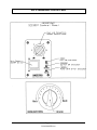
VIII.6 Introduction To The Control Panel
Location of Controls
On freestanding stoves (models J1000B, J2000T) the control switches are located on the right side panel.
On the fireplace insert (model J2001T) the control switches are located on the right shroud leg. On all model
stoves, the Manual Draft Control is located below the Fuel Feed Knob control panel.
ON/OFF Switch
On the right shroud leg of the insert and the right side panel of the stove are the operating switch and knob.
The rocker switch is the Main Power On/Off Switch. This switch controls the electrical power to the entire
stove. Your stove won't start if this switch is in the "OFF" position. Push this switch to the "ON" position. You
should hear the exhaust blower motor turn on.
WARNING: Never turn the Power On/Off switch to the OFF position during the startup cycle if the pellets in
the firepot have ignited. Doing so can cause smoke to billow out.
Please note that if the stove is hot, turning this switch to the "OFF" position will not turn off the exhaust
blower. It will, however, turn off the fuel feed and lower the convection blower speed to the lowest setting.
The exhaust blower will continue to operate until the unit has cooled.
WARNING: Never connect the power supply cord of this unit to an electrical outlet controlled by a wall
switch. Never disconnect the power supply cord to turn this unit off. Always use the ON/OFF Switch that is
installed in the stove.
Fuel Feed Control Knob
Above the On/Off Switch is a silver faced rotary control knob. This control knob has a black pointer arrow
that points at numbers ranging from 1 to 6, when turned. Although numbered 1 through 6, this knob can be
turned incrementally to 20 positions between the numbers 1 and 6. This knob controls the fuel feed rate and
the convection blower speed. #1 is the lowest setting for both fuel feed rate and convection blower speed
and #6 is the highest setting. This control system is designed to increase the convection blower speed in
proportion to the fuel feed rate. In other words, as the fuel feed rate increases, the convection blower speed
also increases. This controlled balance maximizes the efficiency of your stove and also prevents it from
overheating.
NOTE: The Fuel Feed Control Knob will have no effect on the fuel feed rate or the convection blower speed
until the stove has warmed up sufficiently.
Freestanding Stove Draft Control Knob
On the J1000B and J2000T stoves, the Draft Control Knob is located below the main control panel. Around
this knob are numbers ranging from 1 to 6. Note that the knob can be turned in either direction; clock-wise
or counter-clockwise. Setting the knob to 1 provides the least amount of combustion air and setting the knob
to 6 provides the greatest amount of combustion air. See the following paragraph "J2001 Draft Control Knob"
for draft control procedures.
Model J2001T Draft Control Knob
Within the fifth louver opening from the bottom of the right side panel is a round black knob. This is the Draft
or Combustion Air Control Knob. This knob is adjustable from 1 to 6. Setting 1 provides the least amount
of combustion air and setting 6 provides the highest amount of combustion air. To adjust the draft control,
turn this knob counter clockwise 1/4 turn then slide to the desired position. Turn this knob clockwise 1/4 turn
to lock it at the desired position.
Page 39
1998-2006 Edition
VIII.7 Wall Thermostat and Thermostatic Control
NOTE: The control board will not function unless the wall Thermostat Connection Block is jumpered or a wall
thermostat or a wall switch is connected to it. See Section X: Electrical System Information.
Introduction
Thermostatic control is a desirable feature for any heating appliance. A wall thermostat provides the
flexibility of unattended operation while maintaining a comfortable room temperature. Furthermore, it helps
to reduce fuel costs. The Jamestown SCS300T control board provides thermostatic control capability.
Although a wall thermostat is provided as a standard feature with all pellet stove models except the J1000B,
a wall thermostat is not an absolute necessity as heat output control and/or fuel feed rate control capability
is still a standard feature using the Fuel Feed Rate Control Knob on the SCS300T control board. A wall
switch may be used to control the stove "Manually". See Page 58 "Manual Mode".
With most types of wall thermostats, the SCS300T control board can be configured to run in either Automatic
or Semiautomatic Mode. If the thermostat connected is equipped with a "HOLD" feature (commonly found
in programmable wall thermostats) or a switch that allows the thermostat to be fixed in the ON position, then
the stove can be run in the Manual Mode as well. When a wall thermostat is not connected, however, a wall
switch must be connected to the Wall Thermostat connection block on the control board. With a wall switch,
the stove can only be run in Manual Mode. See Section X of this manual for descriptions of Automatic,
Semiautomatic and Manual Modes.
NOTE
Selecting a Wall Thermostat
The SCS300T control board is capable of working together After the 12 minute startup cycle, if the
with a wide range of wall thermostats. With the addition of thermostat is in the "ON" position and if the
the automatic ignition device (which is provided as standard control board determines that the stove has
equipment), the SCS300T control board is also capable of warmed up, the Fuel Feed Control Knob
working together with all modern millivolt programmable can be turned to adjust the fuel feed rate
wall thermostats as well. When purchasing a wall and the convection blower speed.
thermostat, select one that is designed for use with "millivolt If the control board determines that the
systems". Furthermore, to connect the wall thermostat to stove did not warm up sufficiently by the end
the control board, select a two conductor copper wire that is of the 12 minute startup cycle, the fuel feed
will be turned off and an error code will be
a minimum of 18 gauge thick.
Thermostat Operational Characteristics in the flashed using the green STATUS light on the
control panel. The green light will flash once
Automatic Mode
Note: See Section X of this manual for instructions on how every 2 seconds indicating this error status.
to select the Automatic Mode. With the electrical power cord If you encounter this error signal, turn the
connected to a live outlet and with the Main Power switch in Main Power Switch to OFF then back to ON
the ON position, when the wall thermostat is connected to reset the control board.
properly to the stove and then turned to the ON position, the
wall thermostat signals the control board to initiate the
NOTE
preprogrammed startup cycle. The startup cycle is 12 During the 12 minute startup cycle, the Fuel
minutes long. Every time the wall thermostat is turned from Feed Control Knob will be inoperative until
the OFF position to the ON position, the control board will the control board senses that the stove has
initiate the startup cycle.
warmed up. If [within the 12 minute startup
At the onset of the startup cycle, the fuel feed auger is cycle and after the stove has warmed up]
turned on at a predetermined ignition feed rate and the the Fuel Feed Control Knob position is
automatic pellet ignition device is turned on. The ignition changed, the convection blower speed will
device will remain on for the first 5 minutes of the 12 minute vary but the fuel feed rate will remain
startup cycle. The pellets that are in the firepot will ignite unchanged.
Page 40
1998-2006 Edition
within these first 5 minutes. For the remainder of the 12 minutes of the startup cycle, the fuel feed auger will
continue to feed pellets into the firepot at the predetermined warm up rate. If the control board senses that
the stove has warmed up sufficiently at any time during this 12 minute startup cycle, the convection blower
will automatically turn on at the speed determined by the position of the Fuel Feed Control Knob and blow
heated air into the home. The fuel feed rate, however, will remain at its predetermined warm up rate until
the end of the 12 minute cycle. At the end of the 12 minute startup cycle, if the stove has warmed up, the
fuel feed rate is increased to the setting determined by the Fuel Feed Control Knob.
The stove will continue to run at this fuel feed rate and convection blower speed until the wall thermostat
turns to the OFF position. Once the wall thermostat turns to the OFF position, the fuel feed rate will be
turned to OFF. In order to maximize the heat transfer efficiency of the stove and to minimize the probability
of degradation of motor bearing lifetime, however, even with the thermostat in the OFF position, the
convection blower will remain at the speed determined by the position of the Fuel Feed Control Knob as long
as the control board senses that the stove is hot.
Thermostat Operational Characteristics in the Semiautomatic Mode:
Note: See Section X of this manual for instructions on how
to select the Semiautomatic Mode. Read the previous
Automatic versus Semiautomatic
chapter: SCS300T Operating Characteristics in the In Semiautomatic Mode, the stove will
Automatic Mode.
function similarly to in the Automatic mode
With the electrical power cord connected to a live outlet and except that when the wall thermostat turns
with the Main Power switch in the ON position, when the wall to OFF, instead of the fuel feed being turned
thermostat is connected properly to the stove and then to OFF, the fuel feed rate will be turned
turned to the ON position for the first time, the wall down to a predetermined LOW feed rate.
thermostat signals the control board to initiate the The fire will continue to burn.
preprogrammed startup cycle.
The next time the wall thermostat turns to
At the onset of the startup cycle, the fuel feed auger is the ON position, the fuel feed rate will
turned ON at a predetermined ignition feed rate and the increase to the rate determined by the
automatic pellet ignition device is turned ON. The ignition position of the Fuel Feed Control Knob.
device will remain ON for the first 5 minutes of the 12 minute
NOTE
startup cycle. The pellets that are in the firepot will ignite
within these first 5 minutes. For the remainder of the 12 When set in the Semiautomatic Mode, the
minutes of the startup cycle, the fuel feed auger will 12 minute startup cycle can only be
continue to feed pellets into the firepot at the predetermined restarted by turning the main power switch
warm up rate. If the control board senses that the stove has to OFF then to ON. If the electrical power is
warmed up sufficiently at any time during this 12 minute interrupted for any reason, the startup cycle
startup cycle, the convection blower will automatically turn will be initiated when the power is restored
ON at the speed determined by the position of the Fuel and the wall thermostat is turned to the ON
Feed Control Knob and blow heated air into the home. The position.
fuel feed rate, however, will remain at its predetermined
warm up rate until the end of the 12 minute cycle. At the end of the 12 minute startup cycle, if the stove has
warmed up, the fuel feed rate is increased to the setting determined by the Fuel Feed Control Knob.
The stove will continue to run at this fuel feed rate and convection blower speed until the wall thermostat
turns to the OFF position. Once the wall thermostat turns to the OFF position, the fuel feed rate will be
turned to a predetermined LOW setting. The fuel feed will not turn OFF. In order to maximize the heat
transfer efficiency of the stove and to minimize the probability of degradation of motor bearings, however,
even with the thermostat in the OFF position, the convection blower will remain at the speed determined by
Page 41
1998-2006 Edition
the position of the fuel feed control knob for 5 minutes after the thermostat turns to OFF. After these 5
minutes, the convection blower speed will be lowered to a speed equivalent to the #1 position of the Fuel
Feed Rate Control Knob.
NOTE
After the 12 minute startup cycle, if the thermostat is in the "ON" position and if the control board
determines that the stove has warmed up, the fuel feed control knob can be turned to adjust the fuel feed
rate and the convection blower speed.
If the control board determines that the stove did not warm up sufficiently by the end of the 12 minute
startup cycle, the fuel feed will be turned OFF and an error code will be flashed using the green STATUS
light on the control panel. The green light will flash once every 2 seconds indicating this error status. If you
encounter this error signal, turn the Main Power Switch to OFF then back to ON to reset the control board.
Caution
In Semiautomatic Mode, when the thermostat turns to the "OFF" position, the fuel feed rate will automatically
drop down to the #1 setting of the Fuel Feed Knob. The fuel feed does not stop. The draft setting, however,
remains where it was set initially. Therefore, if the unit is connected to a wall thermostat, in order to achieve
maximum combustion efficiency at both the higher feed rate and the default low feed rate, the Draft Knob needs
to be set at one position which allows enough combustion air for burning at both the high burn and the low burn.
This means that you will only be able to set the fuel feed knob at a maximum of about 4 to 4-1/2 because one
draft knob setting must provide enough air to burn the pellets efficiently at two fuel feed knob settings.
Furthermore, the Draft Setting must not be turned up so high that it blows the flame out on the lowest (#1) Fuel
Feed Knob setting.
NOTE: A different burn and flame characteristic will be observed when using a 5/16" (8mm) diameter pellet
vs. a 1/4" (6.35mm) diameter pellet. An adjustment to the draft knob setting may be required when switching
from one brand of pellets to another.
NOTE: Should you feel that the air and fuel adjustments are improper or you just cannot seem to provide
enough air to burn efficiently at any fuel feed control knob setting, first check the Trouble Shooting Guide and
the Periodic Maintenance Requirements section of this manual. If a remedy cannot be found, consult your
local Dealer.
Page 42
1998-2006 Edition
VIII.8 STARTING A FIRE FOR THE FIRST TIME Automatic and
Semiautomatic Modes
Read the section labeled "Introduction to the Control Panel" before attempting to light a fire.
1. Open the fuel hopper lid and check to make sure that no foreign objects, other than wood pellets, are
present inside the hopper. Small quantities of wood pellets may be left in the hopper after the quality
assurance tests performed at the factory or at your Dealer's warehouse.
2. Fill the hopper with 1/4" (6.35mm) diameter pellets.
3. Open the cast iron door and verify that the firepot is seated properly. CAUTION: It is of the utmost
importance that the firepot be seated properly and aligned exactly with the automatic ignition device tube as
shown in the section labeled "Firepot Placement and Alignment". Make sure that the ash pan is closed
tightly and latched. Check around the perimeter of the ash pan gasket to make sure that the gasket is
seating firmly against the stove face. If you see any gaps, turn the two ash pan latches clockwise to close
the gap and tighten the gasket. Similarly, close and latch the cast iron door tightly.
4. Connect the three prong plug at the end of the stove's power cord to a three prong grounded wall outlet.
CAUTION: This stove must be properly grounded at all times. Do not connect the power supply cord to a
wall switched outlet. Never disconnect the power supply cord in order to turn off this pellet stove. Always
use the ON/OFF switch that is installed in this unit.
5. Push the Main Power ON/OFF Switch to the "ON" position. The green POWER ON indicator light will
illuminate.
6. Turn the Fuel Feed Control Knob clockwise to a setting of "6".
7. Turn the Draft Control Knob to "3".
8. Turn the Wall Thermostat to the ON position. The orange IGNITOR ON indicator light will illuminate and
the red FUEL ON indicator light will flash on and off. Since the fuel feed auger system is most likely empty,
it may take up to 7 minutes before you see any pellets dropping into the firepot. NOTE: The only time you
need to "prime" the auger with fuel is when the stove has run out of fuel or when you are starting the stove
for the very first time. When you see pellets start to drop into the firepot, turn the wall thermostat to the
"OFF" position and wait for 5 minutes.
Warning
Do not use flammable liquids such as gasoline or lighter fluid or any type of fire starter materials to start a fire
in your stove.
9. If the control board is set to run in Automatic Mode, after 5 minutes turn the wall thermostat to the "ON" position.
The 12 minute startup cycle will begin. The orange IGNITOR ON indicator light will illuminate and the red FUEL
ON indicator light will flash on and off. Pellets will start to drop into the firepot. Verify the fuel feed rate by counting
the number of seconds the red FUEL ON Indicator light stays ON and also the number of seconds it stays OFF.
See Auger Run Times in Section X.
10. If the control board is set to run in Semiautomatic Mode, after 5 minutes turn the Main Power switch OFF then
ON. Turn the wall thermostat to the ON position. The 12 minute startup cycle will begin. The orange IGNITOR ON
indicator light will illuminate and the red FUEL ON indicator light will flash on and off. Pellets will start to drop into
the firepot. Verify the fuel feed rate by counting the number of seconds the red FUEL ON indicator light stays ON
and also the number of seconds it stays OFF. See Auger Run Times in Section X.
11. The orange IGNITOR ON indicator light will remain lit for 5 minutes. The pellets in the firepot must ignite and
Page 43
1998-2006 Edition
flame up within these 5 minutes. If a flame is present before the end of the 5 minutes, let the stove continue running
without changing any of the controls. If a flame is not present at the end of the 5 minutes, turn the wall thermostat
to the OFF position. Empty the pellets from the firepot into a non-combustible metal container and check the firepot
for proper placement and alignment with the automatic ignition device enclosure tube. Reposition and realign
firepot. Repeat Steps 9 and 10.
Warning
A few glowing embers may be present in the firepot. Never empty the contents of the firepot into the fuel hopper
or any other combustible container.
NOTE
12. If the stove warms up sufficiently during the 12 minute
If
the
stove
does
not
warm up sufficiently by
startup cycle, the convection blower should increase in speed.
Similarly, at the end of the 12 minute startup cycle, the FUEL ON the end of the 12 minute startup cycle, the
indicator light should begin to stay ON for longer periods and FUEL ON indicator light will turn OFF and
stay OFF for shorter periods. An increased amount of fuel the green POWER ON indicator light will
flash once every two seconds indicating that
should begin to feed into the firepot.
13. If the stove is set to run in the Automatic Mode, let the stove the stove did not warm up sufficiently. If this
burn at this rate for 5 minutes. After 5 minutes, adjust the Feed occurs, turn the main power switch to OFF
Rate Control Knob to the desired position, wait 2 minutes then then back to ON and turn the wall
adjust the Draft Control Knob accordingly for an efficient burn. thermostat to the ON position. This will
During the first hour of burn, check for proper air to fuel ratio and reinitiate the 12 minute startup cycle.
efficient flame characteristics and adjust the Draft Control Knob
if necessary. If you plan to leave the Fuel Feed Control Knob at one fixed position for all future burn sessions, it is
not necessary to adjust the Draft Control Knob again. However, check for efficient flame characteristics at least
once a day.
NOTE
14. If the stove is set to run in Semiautomatic Mode, turn the
Fuel Feed Control Knob to a number no greater than 4-1/2, wait When set in the Semiautomatic Mode, the
2 minutes then adjust the Draft Control Knob accordingly for an 12 minute startup cycle can only be
efficient burn. Let the stove burn at this rate for 10 minutes. At restarted by turning the main power switch
the end of the 10 minutes, turn the wall thermostat to the OFF to OFF then to ON. If the electrical power is
position. The fuel feed rate will be lowered to the default LOW interrupted for any reason, the startup cycle
rate. Let the stove burn at this rate for 10 minutes. At the end will be initiated when the power is restored
of the 10 minutes, check for efficient flame characteristics, flame and the wall thermostat is turned to the ON
height and number of embers in the firepot. If the flame height position.
is less than 2 inches and if there are less than about 10 pieces
of embers in the firepot, reduce the Draft Knob setting number
by 1/2. For example:If the Draft Knob was at #3, reduce it to #2-1/2. Check again after 10 minutes. If the flame
height has increased and if the number of embers in the firepot is greater, then turn the wall thermostat to ON. The
fuel feed rate will increase to the rate determined by the position of the Fuel Feed Control Knob. Let the stove burn
at this rate for 10 minutes. Check for efficient flame characteristic. If efficient flame characteristic is not observed,
reduce the Fuel Feed Control Knob setting number by 1/2. Check again after 10 minutes. If necessary reduce the
Fuel Feed Control Knob setting, incrementally, until an efficient flame characteristic is observed.
If you encounter any difficulties achieving a flame within the first 5 minutes or establishing an efficient flame pattern,
please consult the Trouble Shooting Guide in this manual. If you are unable to remedy the problem, please contact
your local Jamestown Dealer.
Page 44
1998-2006 Edition
VIII.9 STARTING A FIRE FOR THE FIRST TIME
Manual Mode
The control system in the stove is set to manual mode if either a wall switch is installed or if a wall thermostat is
connected and is fixed in the ON position.
1. Read and follow instructions (1) through (4) given in Automatic and Semiautomatic Modes - STARTING A FIRE
FOR THE FIRST TIME, on page 41.
2. Turn the Fuel Feed Control Knob clockwise to a setting of "6".
3. Turn the Draft Control Knob to "3" and push the Main Power ON/OFF Switch to the "ON" position.The green
POWER ON indicator light will illuminate.
4. Turn the Wall Switch to the ON position. The orange IGNITOR ON indicator light will illuminate and the red FUEL
ON indicator light will flash on and off. Since the fuel feed auger system is most likely empty, it may take up to 7
minutes before you see any pellets dropping into the firepot. NOTE: The only time you need to "prime" the auger
with fuel is when the stove has run out of fuel or when you are starting the stove for the very first time. When you
see pellets start to drop into the firepot, turn the wall thermostat to the "OFF" position and wait for 5 minutes.
5. After 5 minutes, turn the Main Power switch OFF then ON. The 12 minute startup cycle will begin. The orange
IGNITOR ON indicator light will illuminate and the red FUEL ON indicator light will flash on and off. Pellets will start
to drop into the firepot. Verify the fuel feed rate by counting the number of seconds the red FUEL ON indicator light
stays ON and also the number of seconds it stays OFF.
6. The orange IGNITOR ON indicator light will remain lit for 5 minutes. The pellets in the firepot must ignite and flame
up within these 5 minutes. If a flame is present before the end of the 5 minutes, let the stove continue running without
changing any of the controls. If a flame is not present at the end of the 5 minutes, turn the Wall Switch to the OFF
position, empty the pellets from the firepot into a non-combustible metal container and check the firepot for proper
placement and alignment. See Page 51 of this manual. Reposition and realign the firepot. Repeat Steps 4 and 5.
Warning
A few glowing embers may be present in the firepot. Never empty the contents of the firepot into the fuel hopper
or any other combustible container.
7. If the stove warms up sufficiently during the 12 minute startup
NOTE
cycle, the convection blower should increase in speed. Similarly, If the stove does not warm up sufficiently by the
at the end of the 12 minute startup cycle, the Fuel ON indicator end of the 12 minute startup cycle, the red Fuel
light should begin to stay ON for longer periods and stay OFF ON indicator light will turn OFF and the green
for shorter periods. An increased amount of fuel should begin Power ON indicator light will flash once every
to feed into the firepot.
two seconds indicating that the stove did not
8. Let the stove burn at this rate for 5 minutes. After 5 minutes, warm up sufficiently. If this occurs, turn the
adjust the Feed Rate Control Knob to the desired position, wait main power switch to OFF then back to ON.
2 minutes then adjust the Draft Control Knob accordingly for an This will reinitiate the 12 minute startup cycle.
efficient burn. During the first hour of burn, check for proper air If this problem persists, see Section X on how
to fuel ratio and efficient flame characteristics and adjust the to adjust the control board to increase the fuel
Draft Control Knob if necessary. If you plan to leave the Fuel feed rate during the startup cycle.
Feed Control Knob at one fixed position for all future burn
sessions, it is not necessary to adjust the Draft Control Knob again. However, any time you adjust the Fuel Feed
Rate Control Knob position, you must adjust the Draft Control Knob position to achieve an efficient flame
characteristic.
If you encounter any difficulties achieving a flame within the first 5 minutes or establishing an efficient flame pattern,
please consult the Trouble Shooting Guide in this manual. If you are unable to remedy the problem, please contact
your local Jamestown Dealer.
Page 45
1998-2006 Edition
VIII.10 TURNING OFF THE STOVE
AUTOMATIC MODE
To temporarily stop the stove from outputting heat into the home, turn the wall thermostat to the OFF position. The
fuel will stop feeding instantly. However, the convection air blower will continue to run for 5 minutes at the speed it
was running at immediately before the wall thermostat was turned to OFF. To permanently stop the stove from
running, wait 20 minutes after the thermostat is turned to OFF then turn the main power switch to the OFF position.
Once the stove cools down sufficiently, all motors will stop functioning.
Warning
Do not turn the main power ON/OFF switch to the OFF position while there are pellets burning in the firepot or
while the stove is hot.
SEMIAUTOMATIC MODE
Turn the wall thermostat to the OFF position. The fuel feed rate will decrease to the idle feed instantly. However,
the convection air blower will continue to run for 5 minutes at the speed it was running at immediately before the
wall thermostat was turned to OFF. Let the stove run in idle mode for 10 minutes then turn the main power switch
to the OFF position. Once the stove cools down sufficiently, all motors will stop functioning.
MANUAL MODE
Turn the Wall Switch to the OFF position. Let the stove run at this rate for 20 minutes. Turn the main power switch
to the OFF position. Once the stove cools down sufficiently, all motors will stop functioning.
POWER OUTAGE
In the event of a brown-out, power outage or interruption of electrical power to the stove, the entire system will shut
down; possibly causing sporadic wisps of smoke to escape from the window airwash system temporarily.
When set to run in the Automatic or Semiautomatic modes, if electrical power to the control board is interrupted for
any reason and then restored, the startup cycle will be initiated if the wall thermostat is in the ON position or if in
the OFF position, the startup cycle will be initiated the next time the wall thermostat calls for heat.
When set to run in the Manual mode, if electrical power to the control board is interrupted for any reason and then
restored, the startup cycle will be initiated as soon as the power is restored.
Warning
Never unplug the power cord or disrupt the power supply in any way while the stove is in operation. Doing so will cause
small amounts of exhaust gases and soot particles to leak into the home causing smoke and soot damage.
Caution
During a power outage, do not open the cast iron door. Opening the door can cause excessive smoke and soot
particles to be emitted into the home causing smoke and soot damage.
Jamestown Recommends the use of a Power Inverter
If brown-outs and power outages are common in your area, Jamestown recommends that a power inverter be
employed to power the pellet stove during these conditions. A power inverter is an electronic device that converts
DC power (stored in batteries) to AC power (similar to the home electrical supply and required by all Jamestown
pellet stoves for normal operation). The length of time that the pellet stove will function normally, when employing
a power inverter, depends on the capacity of the battery coupled with the power inverter.
When purchasing a power inverter, verify the following information to ensure that the appropriate model is selected.
Power Inverter Requirement Specifications:
Output 120 Volts, 60 Hertz, 8 Amps, 800 Watts Minimum Continuous Output
Page 46
1998-2006 Edition
IX. MAINTENANCE AND CARE
Providing an annual service and maintenance contract is a common practice among pellet stove Dealers.
Contact your local Jamestown Dealer for information on service and maintenance agreement programs.
Warning
All maintenance should be performed after the stove has been turned "OFF", after all embers have been extinguished
and all parts of the stove have cooled to room temperature.
Most of the problems encountered by consumers with their pellet stoves are directly related to infrequent or
the total lack of routine cleaning. Just as a car requires regular oil changes and tune-ups, pellet stoves also
require regular cleaning and maintenance. Regular cleaning and maintenance can extend the life of motors
and other components of a pellet stove indefinitely. Furthermore, a clean unit burns more efficiently and will
significantly reduce the annual fuel cost.
The cleaning frequency requirements listed below are based on tests conducted at the manufacturer's
facility and data accumulated from the Service and Warranty Department. The information gathered has
shown that if the mentioned cleanings are performed to the schedules given below, the lifetime of the
components in the pellet stove can be extended fourfold.
PERIODIC CLEANING REQUIREMENTS
QUICK REFERENCE GUIDE
Cleaning Requirements and Frequency
1. Cleaning clinkers and/or ash deposits from the inside surface of the firepot and the air wash bracket is
required daily.
2. Emptying the ashpan and cleaning ash deposits from the firebox area of the pellet stove is a weekly
requirement.
3. Cleaning ash deposits from the internal exhaust channels and exhaust pathways is required after burning
one ton (909kg) of pellets (40 bags) or more frequently if the pellets being burned are high in ash content.
4. Once a year, clean the rear compartment where all the motors and blowers are installed. Specifically, clean
the blower impeller.
MAINTENANCE TOOL TIP
A vacuum cleaner with a hose attachment is an invaluable tool for making regular cleaning of the pellet stove
a snap. A pellet stove cleaning kit, part number JR004T, which consists of wire brushes [to scrape stubborn
ash and soot deposits from metal surfaces] and a vacuum hose adapter attachment is available through the
local Jamestown Dealer. It is strongly recommended that this kit be purchased by every pellet stove owner.
Page 47
1998-2006 Edition
1. EVERY TIME BEFORE YOU LIGHT A FIRE
Every time that the fire in the stove needs to be re-lit, perform the following simple cleanings:
FIREPOT/ BURN GRATE: Inspect for accumulation of clinkers inside the firepot and clean. Be sure to inspect the
air inlet holes (in firepot) to make sure they are clear of ash. Fit the firepot properly on the firepot base when
replacing (See Figure C1). After cleaning and each time the firepot is replaced, the firepot must be seated properly.
The outer edges of the firepot underside have been machined to fit properly with the machined top edge of the
firepot base. Make sure that these two edges meet properly and that there is no ash or other debris between them.
An improper or a poor seal between the firepot and the firepot base will yield a lazy burn which will deposit soot on
the glass and firebox walls and will result in drastically low combustion efficiency.
FIREPOT BASE: This is the "empty box" on which the firepot rests. If ash or other debris have accumulated inside
the firepot base, clean completely using a vacuum hose attachment.
AIR WASH BRACKET: See Figure C2. This is the metal bracket that is located along the interior bottom edge of
the door glass. Using a vacuum hose attachment, clean ash deposits from this bracket.
FRAGILE, HANDLE WITH CARE
The Brick Pattern Boards Are Fragile!
When cleaning, remember that the brick pattern boards are very fragile. Do not use a wire brush or any
other object to scrape ash off the brick pattern boards. If soot has deposited on the boards, burn off the
deposit by using a hand held propane torch. Hold the flame on one area of the board until the board
surface glows bright red and slowly move the flame across the surface of the board.
2. ONCE OR TWICE A WEEK
Perform the following cleanings every 3 to 4 days.
FIREBOX AREA: There will be some ash buildup to the side, front and above the insulative brick pattern board.
Remove the ash deposits by using a vacuum cleaner with a hose attachment. The brick pattern boards are fragile.
Be very gentle with them. Do not scrub.
HEAT EXCHANGER TUBES: See Figure C3. Do not touch the scraper rods when the stove is hot. The heat
exchanger tubes will collect fly ash overtime. Three scrapers attached to rods (only one scraper rod on J1000B)
protruding through the front face of the stove (above the door) permits these tubes to be scraped clean. Keep the
stove door closed when scraping the tubes. Pull each scraper rod outward, as far as it travels, and push it back to
its original position, repeatedly. When ash no longer falls when the scraper rod is pulled or pushed, the heat
exchanger tubes are clean. After cleaning, push the rods completely inward to avoid warping the scraper during
normal operation of the stove.
ASH PAN: Open the ashpan only after the stove is cool and all the embers have been extinguished. Remove by
turning the two knobs on the front of the ash pan counter-clockwise and pulling the pan forward. Empty the ash
into a non-combustible container with an air-tight lid. Dispose of the ash after all the embers have cooled thoroughly.
When replacing the ash pan, make certain that the gasket around the perimeter of the ashpan face creates a tight
seal with the firebox face when the ashpan latches are locked.
UPPER SHELVES: See Figure C4. Insert the bottle brush between the heat exchange tubes and the firebox on
each side of the firebox and work the brush in all directions. This will clear a 3/4" (19mm) shelf where fly ash builds
up. Brush in between the heat exchange tubes. Remove the trivet on the top of the stove and tap gently on the top
underneath the trivet until all fly ash has dropped. Vacuum the inside of the firebox.
Page 48
1998-2006 Edition
3. AFTER EVERY ONE TON (909kg or 40 BAGS) OF PELLETS
The Exhaust Channels, Heat Exchangers and Vent System will collect fly ash over time. Fly ash that deposits
in these exhaust pathways reduces the flow of exhaust gases out of the system. If exhaust gas flow out of the
system is reduced, combustion air flow into the firepot will also be reduced. This can lead to lazy burns and
low combustion efficiency. It is critical that these exhaust pathways be cleaned periodically. Jamestown
recommends that all the areas listed below be cleaned, as stated, after every ton of pellets burned.
IMPORTANT Cleaning the through the Wall Kit
- We suggest cleaning your through the wall kit on or before every ton (909kg) of pellets.
- Do not take apart your through the wall kit.
- The pipe is cleaned from the exhaust outside, using your cleaning kit.
- Take Rodent cap off by pulling straight off.
- Using your long brush, insert into stovepipe until you feel resistance. Clean out all build up.
- On a 45º through the wall kit, you will need a 45º through the wall cleaning kit that contains a longer brush.
We highly recommend hiring your Jamestown Dealer to service your stove after your first ton (909kg) of
pellets burned to properly train you in cleaning and maintaining your stove.
SIDE EXHAUST CHANNELS (All Pellet Stoves): See Figure C4. Access Plates to the Side Exhaust Channels
are located on both sides of the interior of the firebox. On J2000T and J2001T model stoves, the Side Exhaust
Channel Access Plates are located behind the side Brick Pattern Boards. It is necessary to remove the side
Brick Pattern Boards before the Side Exhaust Channel access plates can be removed. See Figure C4.
To remove the Brick Pattern Board, use a 5/16" Hex Driver to loosen the screw that holds the Side Brick Pattern
Board retainer bracket in place. Carefully lift the front end of the retainer bracket upward and remove. Carefully
remove the Side Brick Pattern Board from the firebox.
Using a 5/16" Hex Driver, loosen (do not remove) the single screw that holds the Side Exhaust Channel
Access Plate in place. Lift the Access Plate upward until the larger opening in the key hole aligns with the
screw head. Pull the Access Plate outward and remove. On the inner wall of the Exhaust Channel, you will
find a smaller Access Plate that is shaped similar to the one you just removed. This plate provides access
to the Inner Exhaust Channel. Remove this Access Plate using the same method you used to remove the
outer Access Plate.
Using a flash light, look inside the Side Exhaust Channels. If you see excessive soot or creosote deposits, it may
be necessary to remove the Exhaust Blower assembly and clean the impeller blades to prevent damage to the
Blower Motor. Please note that excessive soot deposit means that the Manual Draft setting was too low and
excessive creosote deposit means that the Manual Draft setting was too high. Adjust the Manual Draft setting
accordingly for future burns.
Using a bottle brush, clean all surfaces you can reach in each compartment. It is important to work the bottle
brush in all directions. Lightly tap the walls of the inside walls of the ash compartment and the inside walls of
the firebox. Continue to tap until you can no longer see any fly ash drop. Thoroughly vacuum out these
compartments using a vacuum cleaner with a hose attachment (use the hose attachment from the JR004T
Cleaning Kit). Replace the Access Plates and the side Brick Pattern Boards as before making certain that the
plates create a tight seal.
REAR EXHAUST CHANNEL (Model J2000T and J2001T Only): See Figure C4. Very Carefully, remove the
brick pattern boards on both sides and back of the firebox by first loosening the screw in the bracket at the top
of each brick board, sliding the bracket out and then lifting the board out of the firebox. The Rear Exhaust
Channel Access Plate is located on the back of the firebox towards the left side. Remove this Access Plate.
Using a flash light, look inside the Rear Exhaust Channel. If you see excessive soot or creosote deposits, it may
be necessary to remove the Exhaust Blower assembly and clean the impeller blades to prevent damage to the
Blower Motor. Please note that excessive soot deposit means that the Manual Draft setting was too low and
excessive creosote deposit means that the Manual Draft setting was too high. Adjust the Manual Draft setting
accordingly for future burns.
Page 49
1998-2006 Edition
Using a bottle brush, clean all surfaces you can reach in the compartment. It is important to work the bottle brush
in all directions. Lightly tap the walls of the inside walls of the ash compartment and the inside walls of the
firebox. Continue to tap until you can no longer see any fly ash drop. Thoroughly vacuum out this compartment.
Replace the Access Plate and the side and rear Brick Pattern Boards as before making certain that the plates
create a tight seal.
FIREBOX FLOOR EXHAUST CHANNEL (MODEL J1000B ONLY): See Figure C4. Remove the ashpan.
Located on the firebox floor, under the ashpan, are two round plates. These are the Access Plates to the Firebox
Floor Exhaust Channel. Lift up and remove these plates. Using a bottle brush, clean all surfaces you can reach
in the compartment. It is important to work the bottle brush in all directions; as far to the left and right sides as
possible. Push the vacuum attachment hose as far as possible to the front sides to clean the inner side bottom
channel shown in Figure C4. Thoroughly vacuum out this compartment. Replace the Access Plates as before
making certain that the plates sit flat on the firebox floor.
CAUTION: Installing these access plates with worn gaskets can cause room air to enter the heat exchanger
chambers causing excessively lazy burns in the firepot. Replace the gaskets under the heat exchanger access
plates every time these access plates are removed. Use only Jamestown authorized gasket material. Contact
the local Jamestown Dealer for the availability of gasket material.
EXHAUST SYSTEM: Inspect the spark arrester/ rain cap and clean any accumulated debris off the screen or
slots. Inspect and clean the Clean Out T connector, elbows and pipe as necessary. When reassembling cover
plates, caps or any vent system components that have been disassembled, reseal all joints with RTV red silicone
to ensure an air tight seal. Important: The spark arrester/rain cap should be inspected more often; especially
during the fall when leaves can get caught in the spark arrestor/rain cap openings.
SEALS AND GASKETS: If at any time, the flame in the stove tends to "lick" toward the door glass excessively
or if the draft setting has to be increased significantly (as compared to before) to achieve a clean burn at a
particular fuel feed knob setting, the door gasket, ash pan gasket or glass gaskets may have come loose or
gotten worn down. Inspect the gasket on the door, ash pan and glass monthly and replace as needed. See
page 50 for gasket replacement schedules.
4. Once a Year
Once a year, clean the rear components compartment where all the motors and blowers are installed. Lint and dust
will collect in this compartment over time. Specifically, clean the blower impeller. Dust will collect on the vanes
causing the blower wheel to spin out of balance. An out of balance blower will cause excessive blower noise and
can cause premature failure of the motor bearings. If the interior of the home has been exposed to high levels of
dust particles [due to drywall repair or other remodeling] more frequent cleaning of the blower impeller may be
required.
Clean the blower wheel vanes by first loosening the built up dust by scrubbing lightly with an old tooth brush then
using a vacuum hose attachment to remove the dust.
NOTE: Blower motors that fail due to excessive dust buildup on the blower impeller will be viewed as misuse and/or
abuse and is not warranted.
Caution
If you do not follow all of the above maintenance schedules, this pellet stove will not perform up its potential. High
Energy Manufacturing Ltd. will view this as misuse and abuse and will void all applicable warranties on your unit.
Page 50
1998-2006 Edition
5. AUGER SYSTEM CARE/AUGER JAMS
The auger and auger motor in this Jamestown stove are of the highest quality available. The entire auger
and auger tube are precision machined and assembled to promote self cleaning and to eliminate "hard
pellet" jams. However, it is very important that foreign objects of any kind (such as children's toys, screws,
nails, nuts and bolts, etc.) are not allowed into the fuel hopper.
Pellets of high densities (harder) do not contribute significantly to auger jams. Pellets that are excessively
soft, however, can lead to frequent jams. Soft pellets tend to fall apart easily and form sawdust. Sawdust,
unlike whole pellets, does not fall down the pellet drop tube easily. This characteristic of sawdust can cause
it to be compacted at the front end of the auger. The compacted sawdust will jam the auger. If a bag of
pellet fuel contains excessive amounts of sawdust, do not pour the sawdust into the fuel hopper.
In the event something does "jam" the auger system, disconnect the electrical power supply to the stove and
remove all pellets from the fuel hopper.
If any foreign objects are jamming the auger, remove the object using a pair of pliers or a pair of vise grips.
If the object is difficult to remove, open the right side panel of the stove. Remove the auger motor bracket
mounting nuts and remove the auger motor bracket. Rotate the auger motor back and forth until the object
jamming the auger is free. If the jam is extremely stubborn, remove the auger assembly (the local
Jamestown Dealer may have to help you with this). Clear the obstruction and reassemble.
If no foreign objects are visible, use a pair of vise grips to hold the auger shaft (do not hold the auger spindle)
and rotate the shaft back and forth until it is free of the jam.
STORING PELLET FUEL
When storing pellet fuel, do not place the pellet fuel bags directly on any wet floors or on concrete floors.
Always store pellet fuel raised off the floor and on top of a wooden pallet or a similar pedestal. Storing pellet
fuel bags directly on concrete floors or wet floors will cause moisture to condense inside the bag. This
moisture will soften the pellets and cause them to fall apart and form sawdust.
Page 51
1998-2006 Edition
6. GASKET MATERIALS MAINTENANCE RECOMMENDATIONS
In order to maintain the high combustion efficiency, reduce annual fuel cost, extend the operational life and
ensure safe operation of the pellet stove, Jamestown highly recommends that all gasket materials be
inspected at least annually and adjusted or replaced as necessary. The table below shows the frequency of
inspection and replacement of the various gasket materials.
A replacement gasket kit (part # 03HAA) is available at any Jamestown Dealer. Instructions for replacing all
the gaskets are included with the gasket kit.
Gasket Type
Pellet Stove
Model
Door Gasket
All
Ashpan Gasket
Inspection
Frequency
Replacement
Frequency
Comments
Monthly
As needed or
every 2 tons
(1818kg)
Inspect door gasket seal every time door is opened
and closed for proper seal. If seal is poor and door
gasket cannot be adjusted to create the required
seal, replace.
All
Monthly
As needed or
every 2 tons
(1818kg)
Inspect ashpan gasket seal every time door is
opened and closed for proper seal. If ashpan gasket
cannot be adjusted to create the required seal,
replace.
Glass Gasket
All
Every Ton
Annual
Replace annually.
Exhaust Blower
Gasket
All
Annual
During Exhaust
Blower
Replacement
Replace this gasket every time the exhaust blower is
removed for cleaning or replacing blower motor.
Page 52
1998-2006 Edition
Page 53
1998-2006 Edition
Page 54
1998-2006 Edition
Page 55
1998-2006 Edition
Page 56
1998-2006 Edition
X. ELECTRICAL SYSTEM INFORMATION
All Jamestown pellet stoves or inserts are designed with operational safety in mind. The following electrical safety
devices are included with every stove:
1. Full System 10 amp Fast Acting Fuse Protection
2. Thermal or Impedance Protection on All Motors
3. High Temperature Limit Switch
4. Low Temperature Limit Switch
5. Exhaust Blower Motor Failure and Exhaust System Blockage Protection Vacuum Switch
Caution
Only certified or qualified service technicians should perform analytical, repair or modification work. No other
adjustments may be made to the control system except those specified in this section.
INTRODUCTION TO THE SCS300T CONTROL BOARD
The SCS300T control board is a digitally programmed
control board designed solely for controlling Jamestown
pellet stoves. This control board employs a microprocessor
that drives the functions of the stove.
All four models of Jamestown pellet stoves [J1000B,
J2000T and J2001T and] will function identically. However,
each pellet stove model is programmed with its own unique
function parameters such as fuel feed rate, convection
blower speeds and automatic ignition cycle times. For your
safety, maximum and minimum fuel feed rates and
convection blower speeds are predetermined and
programmed and are not adjustable except as specified in
this section.
Please refer to the diagram of the control board to the right.
Located above the Small Wiring Block is the Program
Selector Switch.
Please refer to the diagram of the Program Selector Switch to the right. The
program selector switch has ten different positions. The Selector Switch
positions are numbered 0, 1....9. The arrow tip points to the number of the
program that is selected. To change the position of the arrow tip (and to
change the program), use a NON-MAGNETIC flat screw driver that has a tip
that is no larger than 1/10 inch (2.5mm) to rotate the arrow. When the arrow
is pointing to a number, for example, "1", the control board runs a program
using parameters that are given in Row #1 in the Program Parameters Tables
given on page 56. The Row Number corresponds to the position of the arrow
tip on the Program Selector Switch.
Page 57
1998-2006 Edition
PROGRAM SELECTOR SWITCH
CONTROL BOARD PROGRAM PARAMETERS TABLES
The control board uses the parameters in the following tables from the Row # that corresponds to the
selector switch position. The tables below list the various parameters specific to each model. When
changing the program, please refer to the table that is specific to the model of stove you purchased.
TABLE X1: J1OOOB PROGRAM PARAMETERS
Program
selector
switch #
Mode
High Fuel
ON Time
(Sec)
High
Fuel
OFF
Time
(Sec)
Low Fuel Low Fuel
ON Time OFF
Time
(Sec)
(Sec)
Convection
Blower Low
Limit
Voltage
(Volts AC)
Convection
Blower High
Limit Voltage
(Volts AC)
STARTUP
CYCLE
TOTAL LENGTH
(Min)
STARTUP
CYCLE
Heater ON Time
(Min)
STARTUP
CYCLE
Fuel ON Time
(Sec)
STARTUP
CYCLE
Fuel OFF Time
(Sec)
0
Auto
6
4
2.5
7.5
100
120
12
5
3
7
1
Auto
6
4
2.5
7.5
105
120
12
5
3
7
2
Auto
6
4
2.5
7.5
100
120
12
5
3.5
6.5
3
Auto
6
4
3
7
105
120
12
5
3.5
6.5
4
Auto
5.5
4.5
3
7
105
120
12
5
3
7
5
Semi
6
4
2.5
7.5
100
120
12
5
3
7
7
Semi
6
4
2.5
7.5
105
120
12
5
3
7
8
Semi
6
4
2.5
7.5
100
120
12
5
3.5
6.5
8
Semi
6
4
3
7
105
120
12
5
3.5
6.5
9
Semi
5.5
4.5
3
7
105
120
12
5
3
7
TABLE X2: J2000T and J2001T PROGRAM PARAMETERS
Low Fuel
OFF Time
(Sec)
Convection
Blower Low
Limit Voltage
(Volts AC)
Convection
Blower High
Limit Voltage
(Volts AC)
STARTUP
CYCLE
TOTAL
LENGTH (Min)
STARTUP
CYCLE
Heater
ON Time (Min)
STARTUP
CYCLE Fuel
ON Time
(Sec)
STARTUP
CYCLE
Fuel OFF Time
(Sec)
2.5
2.5
Low Fuel
ON
Time
(Sec)
25
2.5
7.5
7.5
100
105
120
120
12
12
5
5
3
3
7
7
7.5
2.5
2.5
7.5
100
120
12
5
3.5
6.5
7.5
2.5
3
7
105
120
12
5
3.5
6.5
3
7
105
120
12
5
3
7
2.5
2.5
7.5
7.5
100
105
120
120
12
12
5
5
3
3
7
7
Program
selector
switch #
Mode
High Fuel High Fuel
OFF Time
ON
Time (Sec) (Sec)
0
1
Auto
Auto
7.5
7.5
2
Auto
3
Auto
4
Auto
6.7
3.3
5
6
Semi
Semi
7.5
7.5
2.5
2.5
7
Semi
7.5
2.5
2.5
7.5
100
120
12
5
3.5
6.5
8
Semi
7.5
2.5
3
7
105
120
12
5
3.5
6.5
9
Semi
6.7
3.3
3
7
105
120
12
5
3
7
Page 58
1998-2006 Edition
PROGRAM SELECTION INFORMATION FOR ALL STOVE MODELS
Selector Switch positions numbered 0 through 4 will cause the microprocessor to run in the Automatic Mode
if the stove is connected to a wall thermostat and in the Manual Mode if connected to a wall switch. Selector
switch positions numbered 5 through 9 will cause the microprocessor to run in the semiautomatic mode.
Please note that the parameters in the #0 position are identical to those in the #5 position. The parameters
in the #1 position are identical to those in the #6 position and so on.
Positions #0 and #5 provide parameters for ideal and normal conditions.
Positions #1 and #6 provide parameters for rural areas that are subject to low line voltage situations. The
microprocessor calculates the convection low limit voltage based on a line voltage of 120 VAC. During low
voltage situations, the Convection Blower Low Voltage Limit causes the blower to turn too slowly during low
burn. Since this condition promotes frequent overheating of the stove, the convection blower circuit low limit
voltage has been increased to allow higher convection blower speeds during low burn.
Positions #2 and #7 provide parameters for conditions in which the stove does not warm up sufficiently
during the 12 minute startup cycle. For these situations, the fuel feed rate for the 12 minute startup cycle
has been increased. This increased fuel feed rate during the startup cycle will guarantee that the stove
warms up sufficiently by the end of the 12 minute startup cycle.
Positions #3 and #8 provide parameters for conditions where during low burn, the pellet fuel is consumed
too fast and causes the fire to be extinguished frequently. This is generally a direct result of the pellet fuel
density being too low or, in low altitude installations, too much combustion air being supplied at the lowest
draft setting. For these situations, the fuel feed rate during the low burn periods has been increased. Since
this increase can potentially lead to a overheated unit, the Convection Blower Low Voltage Limit has been
increased as well. Furthermore, the startup cycle fuel feed rate has also been increased to guarantee a
sustained flame during the startup cycle.
Position #4 and #9 provide parameters for high altitude installations. The maximum fuel feed rate has been
decreased by 10%, the low burn fuel feed rate has been increased by 20% and the startup cycle fuel feed
rate has been increased by 17%.
DEFINITIONS OF THE THREE CONTROL MODES
Automatic Mode: This mode is defined as the mode in which the stove functions similarly to a gas fired
furnace. The wail thermostat or wall switch controls the ON/OFF cycles of the stove and attempts to control
the room air temperature. Once the unit has warmed up, the fuel feed rate can be controlled by turning the
Fuel Feed Control Knob. Though the system is termed "automatic", the combustion air volume must be
controlled using the Manual Draft Control Knob.
Each time the wall thermostat calls for heat, the stove will automatically default to its pre-programmed 12
minute startup cycle. During the startup cycle, the fuel is ignited employing the auto ignition device (which
is included as a standard feature) and the stove is allowed to warm up at a controlled fuel feed rate for 12
minutes.
During the startup cycle, if the control board determines that the stove has warmed up (stove is considered
to be warmed up if the 110ºF (43.3ºC) snap disk thermostat is ON), the convection blower speed will
automatically increase to the setting determined by the position of the Fuel Feed Control Knob. At the end
of the startup cycle, if the 110ºF (43.3ºC) snap disk thermostat is ON, the fuel feed rate will increase to the
setting determined by the position of the Fuel Feed Control Knob. The stove will then continue to run at that
fuel feed rate and convection blower speed until the room temperature reaches the temperature set on the
wall thermostat.
At the end of the 12 minute startup cycle, if the control board determines that the stove did not warm up, the
fuel feed will be shut off and an error code will be flashed using the green light on the control panel. If this
error code is encountered, the Main Power Control Switch must be turned to OFF then to ON to restart the
stove. Toggling the wall thermostat from ON to OFF then to ON will not restart the stove. This is a safety
feature built into the control system and is not a bug. If electrical power to the control board is interrupted
for any reason and then restored, the startup cycle will be initiated if the wall thermostat is in the ON position.
Page 59
1998-2006 Edition
If in the OFF position, the startup cycle will be initiated the next time the wall thermostat calls for heat.
When the room temperature reaches the temperature set on the wall thermostat, the fuel feed will be turned
to OFF. The convection blower, however, will continue to run for 5 minutes at the speed determined by the
position of The Fuel Feed Control Knob immediately before the thermostat turned to OFF. This feature
maximizes the stove's heat transfer efficiency and also prevents overheating of the various stove
components.
NOTE: During the startup sequence, while employing the Automatic Mode, the Fuel Feed Control Knob will
have no control over any function of the stove. After the startup sequence, however, the fuel feed control
knob position can be changed to control the fuel feed rate and the convection blower speed.
Semiautomatic Mode: This mode is defined as the mode in which the stove functions similarly to a stove
set in the Automatic Mode except for the fact that when the room temperature reaches the temperature set
on the wall thermostat, instead of the fuel feed being turned to OFF, the fuel feed rate will be lowered to a
predetermined LOW rate. The convection blower, however, will continue to run for 5 minutes at the speed
determined by the position of the Fuel Feed Control Knob immediately before the thermostat turned to OFF.
This feature maximizes the stove's heat transfer efficiency and also prevents overheating of the various stove
components. At the end of the 5 minutes, the convection blower speed will be automatically lowered to the
default low blower speed.
The stove will continue to run at this LOW rate until the room temperature drops below the temperature set
on the wall thermostat.
Once the room temperature drops below the temperature set on the wall thermostat, the thermostat will turn
to ON and the fuel feed rate and the convection blower speed will automatically increase to the rate
determined by the position of the Fuel Feed Control Knob.
NOTE: When in the Semiautomatic Mode, the startup cycle can only be initiated by toggling the Main Power
Switch to OFF then to ON. Toggling the wall thermostat to OFF then to ON will not initiate the startup cycle.
This is a safety feature built into the control system and is not a bug. If electrical power to the control board
is interrupted for any reason and then restored, the startup cycle will be initiated if the wall thermostat is in
the ON position or if in the OFF position, the startup cycle will be initiated the next time the wall thermostat
calls for heat.
Manual Mode: This mode is only set when a wall switch is installed or an installed wall thermostat is fixed
in the ON position. To set the control board into the manual mode, install a wall switch and connect it to the
Thermostat Connection Block on the control board or fix an installed thermostat in the ON position. The
Program Selector Switch must be set on positions 0,1, 2, 3 or 4. When the main power switch is turned to
on, the startup cycle is initiated. The remainder of the functions will be identical to Automatic Mode except
that the fuel feed rate will never turn to OFF. Fuel feed rate can be controlled manually after the startup cycle
by turning the fuel feed control knob. When in the manual mode, the startup cycle can only be restarted by
toggling the wall switch to OFF then to ON. If electrical power to the control board is interrupted for any
reason and then restored, the startup cycle will be initiated if the wall switch is in the ON position or if in the
OFF position, the startup cycle will be initiated the next time the wall switch is turned to the ON position.
SCS300T Circuit Board Adjustment
Prior to shipment, each circuit board's Program Selector Switch is set at #0 and, therefore, is set to run in
the automatic mode. However, some on site adjustment may be necessary due to variations in fuel quality,
electrical power line voltage, installation altitude and customer's preference of heating method.
Warning
All Control Board adjustments should be performed only after reading this entire section thoroughly. Failure to read and
understand this section can lead to improper operational adjustments which can result in a situation that may cause fire
hazards or Carbon Monoxide poisoning hazards.
Page 60
1998-2006 Edition
Page 61
1998-2006 Edition
Page 62
1998-2006 Edition
XI. TROUBLE SHOOTING GUIDE
Save yourself time and money. When in doubt, consult this trouble shooting guide first. Before you call your Dealer,
please read through the SYMPTOMS column. Most of the common problems that you may encounter are listed
under that column. Each PROBABLE CAUSE has a corresponding SOLUTION and is numbered accordingly. In
most instances, you will be able to solve the problem on your own by following this TROUBLE SHOOTING GUIDE.
Warning
DO NOT ATTEMPT TO OPERATE YOUR NEW STOVE UNTIL YOU HAVE READ SECTIONS VIII AND X OF THIS
MANUAL IN THEIR ENTIRETY.
SYMPTOM # 1
Turning the On/Off switch to ON does
not supply electrical power to the stove.
PROBABLE CAUSE
1. Power Cord not Plugged in.
2. Circuit Breaker is OFF.
3. 10-amp fuse on Control
Board is burnt out.
4. On/Off switch is
defective or other wiring
within the stove is
disconnected or
defective.
SOLUTION
1. Plug cord into 3-prong grounded outlet.
2. Turn Circuit Breaker to ON. If problem
reoccurs, have an electrician check for
overloaded circuits in the home.
3. Replace fuse with a 10-amp fast acting
fuse. If problem reoccurs, contact Dealer.
Have Dealer check entire stove wiring
system for faulty wiring, shorted wiring or
shorted motor windings.
4. Have Dealer check entire stove wiring
system for faulty On/Off switch, faulty
wiring, shorted wiring or shorted motor
windings.
SYMPTOM # 2
PROBABLE CAUSE
SOLUTION
In manual mode, when the wall switch
is turned to ON, the green indicator
light stays ON but the red and orange
indicator lights stay OFF and fuel does
not feed.
1. If a wall switch is
installed, the wall switch
may be faulty.
1. Disconnect the two wires connected to the
wall switch at the switch. If all indicator
lights illuminate when these wall switch
wires are jumpered together, the switch
may be faulty. Consult the Wall Switch
Owner's Manual for more information.
2. Check all wall switch circuit wire
connections, including the connections at
the wall thermostat connection block on
the control board.
2. Wall switch wiring is faulty.
SYMPTOM # 3
PROBABLE CAUSE
SOLUTION
In automatic or semiautomatic modes,
the On/Off switch is ON and the green
indicator light is ON but when the
thermostat is turned to ON, the red
indicator light and the orange indicator
light stay OFF and fuel does not feed.
1. Wall thermostat is faulty.
1. Disconnect the two wires connected to the
wall thermostat at the thermostat. If all
indicator lights illuminate when these wall
thermostat wires are jumpered together,
wall thermostat may be faulty. Consult the
Owner's Manual for the wall thermostat.
2. Check all wall thermostat circuit wire
connections, including the connections at
the wall thermostat connection block on
the control board.
2. Wall thermostat wiring is
faulty. Please note that
if a wall thermostat is
not being used, the wall
thermostat connection
block must be jumpered.
Page 63
1998-2006 Edition
SYMPTOM #4
The On/Off switch is ON, the green
light is ON, the orange light is ON and
the red light flashes but fuel does not
feed into firepot.
PROBABLE CAUSE
1. Fuel Hopper is empty.
2. Auger is empty and
needs to be primed with
pellets.
3. Auger is "Jammed".
4. 250F (121ºC) high limit
switch is stuck in the OFF
position.
5. Wires to vacuum switch
are disconnected.
Vacuum hose is plugged
or Vacuum Switch is
faulty.
6. Dirty, weak or defective
combustion blower.
7. Plugged vent system.
8. Wiring in stove is faulty
or Auger motor is faulty
or damaged.
SYMPTOM #5
Stove burns normally during the 12
minute Startup Cycle. After the 12
minutes, however, the fuel stops
feeding and the green Status light
flashes once every 2 seconds.
PROBABLE CAUSE
1. Stove is not warming up
sufficiently within the 12
minutes.
Page 64
1998-2006 Edition
SOLUTION
1. Fill Fuel Hopper with Pellets.
2. Let stove run in this condition for 5
minutes or until pellets start to drop. Turn
main power switch to OFF and wait 10
minutes. After 10 minutes, turn main
power switch to ON and wall thermostat to
ON.
3. Empty Fuel Hopper of Pellets and check
for foreign object in the auger that is
Jamming the auger.
4. Press red reset button on 250F (121ºC)
high limit switch. If pellets start to feed, then the
stove had overheated and the 250F (121ºC)
switch turned off. If pellets still do not feed,
check continuity across the 250F (121ºC) switch
terminals. If continuous, see Probable
Cause #5 and check all auger circuit wiring
for faulty wires or loose connections.
5. Turn On/Off switch to Off. Disconnect
Vacuum hose at the connection under
combustion blower. Place hose end in
mouth and create a high suction. Check
for continuity across the two terminals on
the vacuum switch while maintaining
suction. If no continuity, check vacuum
hose for plug. If vacuum hose is not
plugged, vacuum switch is faulty. Replace
vacuum switch.
6. If vacuum switch system checks OK,
check the exhaust blower. Vacuum switch
will not turn on if exhaust blower is not
turning and creating proper vacuum. If
exhaust blower does not turn when direct
power is applied, replace exhaust blower
motor.
7. Stove is designed so that a plugged vent
system will prevent vacuum switch from
turning ON. Check vent system for plugs.
Clean vent system. Entire stove and vent
system must be cleaned annually.
8. Check system wiring and auger motor.
Connect auger motor to direct AC power.
If motor does not turn, motor is defective,
replace.
SOLUTION
1. See Section X: Electrical System
Information in this manual. Specifically,
refer to Program Selection Information and
Control Board Program Parameters Table.
SYMPTOM #6
PROBABLE CAUSE
SOLUTION
The main power switch is ON and all
lights are working properly. However,
when the Fuel Feed Control knob is
turned up or down, there is no variation
in convection blower speed or fuel
feed rate.
1. Stove is still running in
the 12 minute Startup
Cycle and has not
warmed up sufficiently
yet.
1. There will be no variation in convection
blower speed until the stove warms up and
there will be no variation in fuel feed rate
until stove has warmed up and the 12
minute cycle is complete. Wait until the
12 minute cycle is completed.
SYMPTOM #7
PROBABLE CAUSE
SOLUTION
Fuel feed rate and the Convection fan
speed are irregular or fluctuate.
1. Stove is connected to
electrical power using an
extension cord that is
too long.
2. Voltage supply to the
house is fluctuating or is
too low.
3. Main Control Board
processor chip is faulty.
SYMPTOM #8
On/Off switch is OFF but Exhaust
blower and Convection fan continue to
run.
PROBABLE CAUSE
1. Stove is still hot.
2. Low Temperature
Sensor(130F/54ºC sensor) is
faulty (stuck in the ON
position).
SYMPTOM #9
Stove burns normally then, suddenly,
fuel stops feeding to firepot and fire
goes out but all the indicator lights
continue to work normally.
1. Do not use extension cords to supply
power to the stove. An extension cord that
is too long or one that is made of wire of
low gauge will reduce the voltage supplied
to the stove. Contact an electrician to
install a proper power supply line to the
stove.
2. Contact an electrician or the local power
company. Check voltage fluctuation.
Adjust so that voltage is at least 110VAC.
3. If problem still exists after checking steps 1
through 3, Main Control Board is faulty.
Replace.
SOLUTION
1. Allow stove to cool for about 1-1/2 hours.
Exhaust blower and convection fan are
designed to stay on until stove cools down
completely.
2. If stove has been cold for several hours,
check for continuity across Low
Temperature Sensor (130F/54ºC sensor)
terminals. If continuous, replace 130F (54ºC)
sensor.
3. Improper wiring of
several internal
components.
3. If stove was "worked on" recently, several
components within could have been wired
improperly. Contact Dealer. Check wiring
thoroughly according to this manual and
correct any problems.
PROBABLE CAUSE
1. High limit sensor has
overheated and turned
the fuel feed off.
SOLUTION
1. Check to see if the Green Light is ON. If
it is OFF, toggle the On/Off switch to Off
then On. Press the Reset Button. If the
green light does not illuminate, it is
confirmed that the high limit switch has
tripped. Check fuel feed rate on High and
on Low. If it conforms to this manual,
increase the Convection Blower LOW
SPEED setting. Refer to Control Board
adjustments section of this manual.
2. Empty fuel hopper of pellets and check
auger for foreign objects. Remove foreign
object from auger.
2. Auger has jammed.
Page 65
1998-2006 Edition
SYMPTOM #10
PROBABLE CAUSE
SOLUTION
When the Fuel Control Knob is set on
"1", the stove seems to burn normally
for a while but, eventually, the fire
goes out.
1. Draft Control Knob is set
too high.
1. Reduce the Draft Control Knob Setting
when burning on the "1" setting of the Fuel
Control Knob.
2. At lower altitudes, the higher oxygen
density in the air may cause the pellets to
burn too quickly. Although the efficiency
of the stove is significantly higher, the
pellets may burn too fast to maintain the
fire. Adjust the LOW fuel feed rate on the
control board higher according to this
manual. Specifically, consult Page 56
"Control Board Program Parameters
Tables" and Page 57 "Program Selection
Information". Contact your Dealer for more
detailed instructions.
SYMPTOM #11
The Fuel Control Knob is set on "1" (or
the wall thermostat is in the OFF
position if running in Semiautomatic
mode) and burned overnight. In the
morning, the firepot is full of unburned
pellets and fire is out.
PROBABLE CAUSE
1. Draft Control Knob is set
too high.
2. Fuel Feed Setting on
control board is set too
low.
2. Fuel Feed Setting on
control board is set too
low.
3. Pellets are tunneling
inside the hopper
(pellets are not sliding
down the hopper sides).
Page 66
1998-2006 Edition
SOLUTION
1. Reduce the Draft Control Knob Setting
when burning on the "1" setting of the Fuel
Control Knob.
2. At lower altitudes, the higher oxygen
density in the air may cause the pellets to
burn too quickly. Although the efficiency
of the stove is significantly higher, the
pellets may burn too fast to maintain the
fire. Adjust the LOW fuel feed rate on the
control board higher according to this
manual. Specifically, consult Page 56
"Control Board Program Parameters
Tables" and Page 57 "Program Selection
Information". Contact your Dealer for more
detailed instructions.
3. Clean hopper inner surface and apply
Teflon lubricant spray to entire surface.
SYMPTOM #12
No matter how much I try, I cannot
seem to set the air to fuel ratio
properly to obtain an efficient burn on
the "6" setting (or "1") of the Fuel Feed
Control Knob.
PROBABLE CAUSE
1. Air intake hose may be
pinched or plugged.
2. Draft control valve
(butterfly valve) may be
set improperly or
reversed.
3. Draft Knob setting is too
low.
4. Fuel Feed Rate on
"High" is too high.
5. There may be an air
leak between the firepot
and firepot base. The
firepot may not be
seating property. The
bottom of the firepot
may be burned out.
6. There may be an air
leak through the door
gasket or ash pan
gasket.
7. Exhaust flow paths
and/or heat exchangers
are plugged with ash.
8. Vent system is plugged.
SYMPTOM #13
Door glass blackens up rapidly, the
stove does not seem to heat
adequately and there are, what seems
to appear as, sandy globs (clinkers), at
the bottom of the firepot.
PROBABLE CAUSE
1. Draft Knob setting is too
low for the Fuel Feed
Knob setting.
2. The firepot is not being
cleaned often enough.
3. The pellets being burned
are of inferior quality and
contain excessive
quantities of sand, dirt
and moisture.
Page 67
1998-2006 Edition
SOLUTION
1. Check air intake hose and clear all debris
that may be stopping combustion air flow.
2. Check and make sure that when the Draft
Knob is in the "6" position, the butterfly
valve is horizontal. If not, loosen draft
knob set screw and adjust accordingly.
3. Increase the Draft Knob setting. Look for
a bright white flame with blue hues near
the firepot. Flame should not be engulfing
the heat exchanger tubes.
4. If the Draft Knob is on "6" and the flames
still have black tips and/or are engulfing
the heat exchanger tubes, the factory
settings may be too high for your altitude.
If you reside at an altitude higher than
5000 feet (1524m), you will need to lower the
"HIGH" fuel feed rating. Specifically,
consult Page 56 "Control Board Program
Parameters Tables" and Page 57
"Program Selection Information". Contact
your Dealer for more detailed instructions.
5. Check the firepot first. Make sure that
there is no ash or other deposits between
the firepot and the firepot base. Make
sure that the firepot is seating properly and
forming a proper seal with the firepot base.
Check the bottom of the firepot. If firepot
bottom is burnt out, replace firepot.
6. Check around the door and the ash pan.
The gaskets should be touching the face of
the stove and compressed. Make sure
that the ash pan gasket is touching the
face of the stove throughout its perimeter.
7. Clean heat exchanger tubes, side exhaust
channels, rear exhaust channel, floor
exhaust channel, side heat exchangers
and exhaust blower assembly.
8. Clean vent system.
SOLUTION
1. Increase the Draft Knob setting. Look for
a bright white flame with a blue hue near
the firepot.
2. Clean the firepot daily. Make sure that all
the air intake holes at the bottom of the
firepot are clean.
3. Clinkers are formed when sand particles
and sap from some types of wood used in
making the pellets join together.
This type of deposit, if it forms rapidly
within 6 hours of burn, indicates a fuel of
inferior quality. Consult your Dealer about
superior quality pellets that are available
in your area.
SYMPTOM #14
Flame is lazy and orange and has
black tips. Visible smoke licks towards
the door glass and sides of the firebox.
Black smoke is visible at the vent cap
at all times and the glass turns black
within a couple of hours.
PROBABLE CAUSE
1. Air intake hose may be
plugged.
2. Draft control valve
(butterfly valve) may be
set improperly or
reversed.
3. Draft Knob setting is too
low.
4. Fuel Feed Rate on
"High" is too high.
5. There may be an air leak
between the firepot and
firepot base. The firepot
may not be seating
properly.
6. There may be an air leak
through the door gasket
or ash pan gasket.
7. Exhaust flow paths
and/or heat exchangers
are plugged with ash.
8. Vent system is plugged.
Page 68
1998-2006 Edition
SOLUTION
1. Check air intake hose and clear all debris
that may be stopping combustion air flow.
2. Check and make sure that when the Draft
Knob is in the "6" position, the butterfly
valve is horizontal. If not, loosen draft
knob set screw and adjust accordingly.
3. Increase the Draft Knob setting. Look for
a bright white flame with blue hues near
the firepot. Flame should not be engulfing
the heat exchanger tubes,
4. If the Draft Knob is on "6" and the flames
still have black tips and/or are engulfing
the heat exchanger tubes, the factory
settings may be too high for your altitude.
If you reside at an altitude higher than
5000 feet, you will need to lower the
"HIGH" fuel feed rate. Specifically, consult
Page 56 "Control Board Program
Parameters Tables" and Page 57
"Program Selection Information". Contact
your Dealer for more detailed instructions.
5. Check the firepot first. Make sure that
there is no ash or other deposits between
the firepot and the firepot base. Make
sure that the firepot is seating properly and
forming a proper seal with the firepot
base.
6. Check around the door and the ash pan.
The gaskets should be touching the face
of the stove and compressed. Make sure
that the ash pan gasket is touching the
face of the stove throughout its perimeter.
7. Clean heat exchanger tubes, side exhaust
channels, rear exhaust channel, floor
exhaust channel, side heat exchangers
and exhaust blower assembly.
8. Clean vent system.
APPENDIX A
J2001T PELLET STOVE
Standard Shroud Kit#J2001TS Installation Instructions
Parts List
1. Shroud Top #C187T
2. Shroud Left Leg #C187L
3. Shroud Right Leg #C187R
4. Hopper Opening Sealer #C373. Included w/stove.
5. Five (5) #8 x 1/2" Hex Head Teck Screws
6. Eight (8) #8 x 1/2" Phil. Pan Head Sheet Metal or Teck Screws.
Tools Required
1. Electric Screw Gun
2. Standard Phillips Screwdriver bit
3. 1/4" Hex Head driver bit
4. 5/16" Open End Wrench
1. Locate the Hopper Opening Sealer (see Figure 1) inside the firebox or inside the hopper. Remove this part.
Unwrap and discard the wrapping material.
2. Identify the steel parts listed above according to Figure 1.
3. Lift the Shroud Top Opening Door [which is hinged to the stove top] and lay it over the stove top trivet so that
the black latch knob is resting on the trivet.
4. Look at Figure 2. Identify the two Hex Head Screws that are attached to the downward bend on the rear of the
stove top. Note that these screws are not tightened completely.
5. See Figure 2 and 3. Slide the Shroud Top behind the stove top while aligning the open slots in the Shroud Top
with the two Hex Head Screws on the Stove top back. Slide shroud top slots between the hex heads and the
stove top. Please note that the shroud top must sit behind the stove top but in front of the outward bends at the
rear end of the stove side panels.The shroud top must be located between the stove top and the outward bend
on the stove side panel.
6. Close the Shroud Top Opening Lid onto the Shroud Top and latch it.Tighten the two hex head screws on the
stove top back using a 5/16" open end wrench so that the shroud top stays in place.Try opening the Shroud Top
Opening Door by turning the latch knob. If the operation is smooth, tighten the two hex head screws securely. If
the operation is not smooth, lift the shroud top upwards 1/16" and tighten the two hex head screws.
7. Align screw hole # [H1] on the side panel with screw hole #[H1] in the shroud top face as shown in Figure 2.
Drive one #8 x 1/2" Phillips head sheet metal screw or Teck screw [4] through these holes.Tighten.
8. Using a 5/16" Open End Wrench, tighten the two hex head screws on the rear of the stove top so as to secure
the shroud top to the stove top.
9. Mount the Control Cover Plate Assembly onto the right shroud leg as shown in Figure 3. Note that when
mounting the Controls Cover Plate Assembly, do not disconnect any of the wires attached to its back side. Slide
the entire control cover plate assembly [with wires attached] through the rectangular hole and then proceed with
mounting the brass screws and nuts.
10.To mount the Shroud Legs onto the stove, align screw hole #[H2] on the shroud leg [3] with screw hole
#[H2] in the shroud top “Z” bend. See Figure 4. Drive one #8 x 1/2" Phillips head sheet metal screw or Teck screw
[4] through these screw holes.
11. Align screw hole #[H3] located at the bottom of the shroud leg with screw hole #[H3] at the bottom of the
outward bend on the stove side panel. Drive a #8 x 1/2" Phillips head sheet metal screw or Teck screw through
these holes.
12. Align and drive one #8 x 1/2" Phillips head sheet metal screw or Teck screw through the remaining holes
#[H4] on the mitered edge along the top edge of the shroud leg.
13. Center the Hopper Opening Sealer (see Figure 5) on the back side of the shroud top. Push the Hopper
opening Sealer against the Shroud top.
14. While holding the shroud top vertically straight, drive one #8 x 1/2” Hex Head Teck Screw through each screw
hole (in the Hopper Opening Sealer) into the hopper top.
15. Seal the joints between the Hopper Opening Sealer and the Shroud Top and Hopper Top with black silicone
or aluminum foil tape.
Appendix A-1
1998-2006 Edition
PLATE FOR INSTALLING
THIS FIREPLACE HAS BEEN ALTERED
TO ACCOMODATE A FIREPLACE INSERT
AND SHOULD BE INSPECTED BY A
QUALIFIED PERSON PRIOR TO RE-USE
AS A CONVENTIONAL FIREPLACE.
THIS PLATE MUST BE AFFIXED TO THE
INSIDE OF THE FIREPLACE VISIBLE
UPON REMOVAL OF THE “INSERT”
Appendix A-2
1998-2006 Edition
Appendix A-3
1998-2006 Edition
Appendix A-4
1998-2006 Edition
Appendix A-5
1998-2006 Edition
Appendix A-6
1998-2006 Edition
APPENDIX B
CAST LEGS J2067T AND GOLD LEGS
J2068T KITS FOR APPLIANCE MODELS
J1000B and J2000T
Installation Instructions
Parts List
1. Four Cast Legs (Black or Gold)
2. Eight 1/4" x 1" (20nc) Bolts
3. Eight Lock Washers
Tools Required
1. Adjustable Wrench
2. Phillips Screw Driver
Caution
If any part of the appliance is damaged during this installation, you will be responsible for the replacement costs. High
Energy Manufacturing Ltd. does not guarantee or warrant any parts that you damage during this installation.
1. After having removed the packaging material from around the appliance, tip the unit on its back and lay it
gently on a non-abrasive surface such as carpeting.
2. Locate the Leg mounting holes according to Figure 1, 2 or 3, depending on the model you
purchased. Please note that each hole has a weld nut on the inside of the stove bottom. Locate the packages
of bolts provided with this leg kit.
3. Attach the legs to the stove bottom using the method shown in Figure 2. Note: For the front legs, the
decorative side of the legs (polished side on gold plated legs) should be facing the front of the unit. For the
rear legs, the decorative side of the legs should be facing the rear of the unit.
4. Thread each bolt into the weld nut by hand; making sure that the bolt and nut thread pattern are not crossthreaded.
5. Hand tighten each bolt.
6. Tighten using an adjustable wrench.
7. Lift the unit to its upright position.
Appendix B-1
1998-2006 Edition
Appendix B-2
1998-2006 Edition
APPENDIX C
COMBUSTION FAN ASSEMBLY
FOR MODELS J2000 & J2001
Complete Assembly is Part#
07DAJ
Appendix C-1
1998-2006 Edition
APPENDIX D
EXHAUST BLOWER ASSEMBLY
MODEL J1000
Complete Assembly is Part#
07DAA
Appendix D-1
1998-2006 Edition
APPENDIX E
AUGER MOTOR & BRACKET
INSTALLATION
Appendix E-1
1998-2006 Edition
APPENDIX F
KWM RELAY KIT #03DAA
Installation Instructions
This kit contains the following parts
One Metal Bracket with Relay, Transformer & Wires mounted
Two #8 - 32nc Phil Pan Hd. self tapping screws
Two 3/16" ID x 3/8" OD Round Washers
Four (4) Blue Snap On Female Connectors
Two (2) Insulated "A" Male Connectors
Four (4) Nylon Wire Ties
One (1) Black wire extension (J2000 models only)
Tools Required
Standard Pliers Wire Stripper
Wire Connector Crimper
Wire Dikes
#2 Phillips Screw Driver bit
Electric Power drill
3/32" Flat Tip Screw Driver
Caution
UNPLUG THE ELECTRICAL POWER SUPPLY CORD FROM THE WALL RECEPTACLE
1. Open both left and right side panels by removing the Phillips head screws that hold the side panels shut. Prop
side panels open.
2. Open box and identify the parts listed above.
3. See Figure 3. Identify all the wires and components that are mounted on the metal bracket. Make sure that all
wiring components are connected according to Figure 3.
4. See Figure 1. Locate the louver slot in the back panel that the Metal Bracket with relay, transformer and wires
is to be mounted in. On the J1000B, select the louver below the top most louver located above the main control
board and directly under the fuel hopper. On the J2000T and J2001T, select the louver below the top most louver
located above the Vacuum Switch (mounted on the back panel next to the left side panel).
5. Attach the Metal Bracket to the back panel using two Phillips self-tapping screws and two metal washers
(provided) as shown in Figure 2.
6. See Figure 4. Identity terminals numbered #2 and #6 on the control board and the Orange wires connected
to these terminals. Also identify the Thermostat Input block and the Red and White wires connected to it.
7. See Figure 4. Using a 3/32" (2.4mm) flat tip screw driver, loosen the screws and pull off the wires connected
to #2, and #6 terminals and the T-STAT block. If any of these wires are tied down with nylon wire ties to the stove
panel or to other wires, cut these nylon wire ties so as to free these wires. Crimp one "A" insulated male
connector (supplied) to the ends of the Orange wire you just pulled off the control board connection block.
8. Disconnect ribbon cable from ON/OFF switch by pushing in white button behind it. Trace the black wire from
terminal #7 on the control board to the ON/OFF switch mounted on the right side panel. Disconnect this black
wire from the ON/OFF switch. Connect wire to right side of Transformer.
9. Identify wire #2 in Figure 3. Connect the loose female end of this wire to the same terminal on the ON/OFF
switch as in step 8.
10. Locate the Blue Crimp ON connectors and crimp them onto wires #2 and #7 in Figure 5. Connect the male
connectors you crimped onto the ends of the Orange wires, in step 7, to these two Blue Crimp ON connectors.
Connect one Orange wire to each Blue Crimp ON connector.
11. Identify wires #5 and #6 in Figure 3. Also Locate the black and white power cord wires. Approximately 2
inches from where the power cord enters the stove compartment through the back panel, crimp one Blue Crimp
ON connector on the black and white power cord wires.
Appendix F-1
1998-2006 Edition
12. See Figure 3. Identify the brown 35" (889mm) long thermostat wire #1, which is connected to the relay.
Connect the loose ends of the red and white wires of this thermostat wire to the Thermostat Input terminals (see
figure #4).
13. Locate the ends of the 25 foot (7.6m) long thermostat wire that was connected to the Thermostat Input
terminals in Step #6. Pull these ends inward until they can reach the Relay Terminals easily. On the J2000 and
J2001T, you will have to pull in about 36" (914mm)of this wire so that it can reach the relay on the opposite side
of the stove.
14. See Figure 3. Identify wire # 3 and RELAY #1 terminal on the relay. Connect the Red thermostat wire to the
butt connector on the end of wire #3.
15. A red female connector is pushed on to RELAY #1 terminal. Remove this female connector, crimp it to the
end of the White thermostat wire then reconnect this female connector back to RELAY #1 terminal.
16. See Figures 3 and 5. Connect wire # 5 to the Blue Crimp ON connector on the black power cord wire.
17. See Figures 3 and 5. Connect wire # 6 to the Blue Crimp ON connector on the white power cord wire.
18. See Figures 3, 4 and 5. Study these diagrams carefully. Only the wiring systems affected by this modification
are shown in these diagrams. Make special note of the wire colors, wire lengths, wire end connectors and their
destinations. Verify that all wires are connected to the proper components. Reconnect ribbon cable. Make sure
the black strip of the ribbon cable is on top.
DO NOT REMOVE OR MODIFY ANY OTHER WIRES OR COMPONENTS THAT ARE NOT SHOWN IN
THESE DIAGRAMS.
Installation of the Relay Kit is now complete.
To test for proper function, follow this procedure:
Warnings
1. Failure to adhere strictly to these printed drawings and instructions can lead to damaged electrical components.
Components damaged due to improper wiring are not warranted.
2. Make certain that the wall thermostat or wall switch is rated for 24 VAC.
1. Turn wall thermostat or wall switch to OFF.
2. Toggle the ON/OFF switch on the right side panel to OFF.
3. Insert the power cord plug into a grounded 110 VAC outlet.
4. Turn the ON/OFF switch to the ON position. All motors, blowers and indicator lights should remain OFF.
5. Turn the wall thermostat or wall switch to the ON position. The combustion fan and convection fan must
start turning.The green indicator light on the control panel must turn to ON and stay ON.The yellow indicator
light on the control panel must turn to ON and stay ON for 5 minutes. The red indicator light must turn ON
and OFF with the auger motor.
If all components and indicator lights work according to the check above, you have successfully wired in the
relay kit. The stove is now ready for fully automatic operation.
Warning
Never turn the wall thermostat or the ON/OFF switch to the OFF position during the 10 minute startup cycle. Doing so
can cause smoke to spill into the home and cause smoke and soot damage.
Appendix F-2
1998-2006 Edition
Appendix F-3
1998-2006 Edition
APPENDIX G
3 PIECE MITERED GLASS KIT
INSTALLATION
GLASS GASKET
03HAA
CENTRE GLASS
04AAB
SIDE
GLASS
04AAA
Step 1: After having installed the Glass Spacer Bracket and the “Airwash” Bracket on the windowsill,
wrap the outer edges of the pieces of glass as shown here with glass gasket material. Wrap each
glass piece using a separate piece of gasket.
Step 2: Place the larger center glass inside the doorsill cavity. Please note that the gasket must be
along the top edge of this glass piece. Also note that at the bottom, the glass must sit behind the
vertical center tab that is part of the glass spacer bracket.
Step 3: Place side glass piece inside the windowsill cavity. Please note that the mitered edge of these
two pieces must butt against the side edges of the center glass and the gasket material on these side
pieces must wrap around the outer and top edge.
(Step 4 on next page)
Warning
Proper care and safety must be followed when removing broken glass. Only use factory approved
replacement glass and gasket material.
Do Not Slam The Door
Caution:
Do not attempt to clean glass while HOT! Allow sufficient time for cooling. Do Not Use Abrasive
Appendix G-1
1998-2006 Edition
3 PIECE MITERED GLASS KIT
INSTALLATION (Continued)
Step 4: Locate the side Gloss Retainer Mounting Holes, These holes should already be drilled and topped
on both sides of the door.
Step 5: Loosely attach one Gloss Retainer Bracket to each side of the cost iron door using one #8 x 1/2” self
topping Phillips screw.
Step 6; Check the joint between the center gloss and the side glass pieces, Center the center piece then
gently push the side glass pieces towards the center pieces until they butt together, lighten the glass retainer
bracket mounting screws carefully.
NOTE: FOR PELLET STOVE APPLICATIONS, IT IS NOT NECESSARY FOR THE JOINT BETWEEN THE
SIDE AND CENTER GLASS TO BE A PERFECT SEAL. GAPS AS LARGE AS 1/32” (0.8mm) ARE
ACCEPTABLE AND WILL NOT AFFECT THE PELLET STOVE FUNCTION.
Step 7: Locate the Glass Retainer Mounting Holes located along the top edge of the center gloss, If there
are two screw holes, attach one glass retainer bracket to these holes by following Steps #5 & #6, If only one
hole exists of the center (along the top edge of the center glass), you will need to use a glass retainer
bracket as a template and mark the center of the two mounting holes, Use a #29 drill bit to drill holes 1/2”
(13mm) deep and tap them using a #8-32nc Tap.
Appendix G-2
1998-2006 Edition
APPENDIX H
J1000 CROSSFLOW FAN
Part# 07EEG
Appendix H-1
1998-2006 Edition
APPENDIX I-1
EXHAUST BLOWER ASSEMBLY
MODEL J1000
Appendix I-1
1998-2006 Edition
APPENDIX J
WARNINGS
Installing Solid Fuel Inserts in Factory Built Fireplaces
1. The insert must be tested and meet the requirements of UL 1482
(U.S.) and or ULC S628 (Canada) when tested in a masonry fireplace built per ULC S628.
2. The factory-built fireplace must be listed per UL 127 or ULC S610.
3. Clearances obtained from the masonry fireplace tests are also relevant for installation in factory built
fireplaces.
4. Installation must include a full height listed chimney liner meeting type HT requirements (2100 degree
F.) per UL 1777 (U.S.) or ULC S635 (Canada). The liner must be securely attached to the insert flue collar
and the chimney top.
5. Means must be provided to prevent room air passage to the chimney cavity of the fireplace, this may be
accomplished by sealing the damper area around the chimney liner, or sealing the fireplace front.
6. The air flow within and around the fireplace shall not be altered by the installation of the insert (ie. No
louvers or cooling air or outlet ports are blocked), unless specifically tested as such for each factory-built
fireplace manufacturer and model line. (Note: using a louvered faceplate [surround] complies with this
requirement).
7. Alteration of the fireplace in any manner is not permitted with the following exceptions:
a) External trim pieces which do not affect the operation of the fireplace may be removed providing they
can be stored on or within the fireplace for reassembly if the insert is removed.
b) The chimney damper may be removed to install the chimney liner.
8. Circulating air chambers (ie. In a steel fireplace liner or metal heat circulator) shall not be blocked.
9. Means must be provided for removal of the insert to clean the chimney flue.
10. Inserts that project in front of the fireplace must be supplied with appropriate supporting.
11. A permanent metal warning label must be attached to the back of the fireplace stating that the
fireplace must be restored to its original condition for safe use without the insert.
Appendix J-1
1998-2006 Edition
SERVICE RECORD
DATE
SERVICED BY
DESCRIPTION
NO TES
P.O. Box 400, Vermilion Bay, Ontario, Canada POV 2V0
Phone: (807) 227-2745 Fax: (807) 227-2172
www.jamestownpelletstoves.ca
cut here
WARRANTY REGISTRATION CARD / GARANTIE ENREGISTREMENT
TYPE OR PRINT CLEARLY IN INK / OU CARACTERES CLAIREMENT DANS ENCRE
NAME
/ NOM:
__________________________________________________________________________________________________________________
ADDRESS
/ ADRESSE:
__________________________________________________________________________________________________________________
C
ITY / LA VILLE:
STATE:
ZIP:
__________________________________________________________________________________________________________________
PHONE
NUMBER / NUMERO DE TELEPHONE: (
)
__________________________________________________________________________________________________________________
MODEL
PURCHASED (CIRCLE ONE) / LE MODELE A ACHETE: (CELUI ENCERCLER):
J1000B J2000T J2001T
__________________________________________________________________________________________________________________
S
ERIAL NUMBER / LE NUMERO DE SERIE: WHHEPURCHASE DATE / LA DATE D'ACHAT:
__________________________________________________________________________________________________________________
DEALER
NAME / LE NOM DE NEGOCIANT:
DEALER LOCATION / L'EMPLACEMENT DE NEGOCIANT:
__________________________________________________________________________________________________________________
Please mail this card after you have burned your stove for a couple of weeks and comment below on whether or not you are happy
with your decision to buy this heater. If not, why; and whether or not you are happy with your Dealer.
S'il vous plaît courrier cette carte après vous a brûlé votre poêle pour quelques semaines et commentaire au dessous sur si vous
sont content de votre décision acheter cet appareil de chauffage. Si non, pourquoi; et si vous êtes content de votre Négociant.
__________________________________________________________________________________________________________________
__________________________________________________________________________________________________________________
Jamestown Limited Five Year Warranty
General: Manufacturer, will furnish a replacement for any part of this product which fails, under normal use and service, within the
applicable periods specified below and in accordance with the terms of this Warranty Policy. The replacement part will be warranted
only for the remaining period of the original warranty.
Steel Parts: If any steel part of the unit fails within five (5) years from the date of the original installation and operation, we will
either repair or furnish a replacement steel part.
Electrical: If any electrical part fails within two (2) years from the date of the original installation and operation will furnish a new
replacement part. Electrical parts include the Exhaust Blower Assembly, Convection Blower Assembly, Auger Motor, Main Control
Board, Control Panel Board, Manual Auger Timer, Vacuum Switch, 110ºF (43.3ºC) Switch, 130ºF (54.4ºC) Switch, 250ºF (121ºC)
High Limit Switch and all electrical wires and electrical connectors. The system fuse on the Main Control Board is not warranted.
This Warranty Will Not Apply To: The firepot, insulative brick pattern board, door gasket, glass gasket, ash pan gasket, exhaust blower
gasket, auger motor mounting bracket gasket, door glass, defects or malfunctions resulting from failure to properly install, operate or
maintain the unit in accordance with the printed instructions provided; to damage from abuse, accident, fire, flood and the like; to parts
or labor in connection with normal maintenance, such as replacing gaskets, cleaning of tarnished brass, or repainting; to units that are
not installed in accordance with applicable local codes, ordinances and good trade practices; defects or damage caused by the use
of any attachment, accessory or component not authorized by us.
Service Labor: This warranty does not cover any labor expenses for service or for removing or reinstalling any parts or the stove
itself. All such expenses are the responsibility of the stove owner unless a service labor agreement exists between the stove owner
and the Jamestown® Dealer selling the stove.
Shipping Costs: You are responsible for all costs incurred in shipping warranty replacement parts from the factory to the
Jamestown® Dealer and from the Dealer to the location of your stove. You are also responsible for all costs incurred in returning the
failed part to the Dealer. If in Alaska or the continental United States, you must also pay the shipping cost of returning the failed part
to the port of entry into Canada.
How To Obtain Warranty Service and Replacement Parts: Normally, the Jamestown® Dealer from whom the unit was purchased
will be able to take the necessary corrective action by obtaining through us any replacement parts. If the dealer is not available,
simply contact any other dealer handling Jamestown products. The name and location of a local Jamestown® Dealer can usually
be found in the telephone directory, on the web site at www.jamestownpelletstoves.ca or by contacting us directly at 1-807-227-2745.
However, all replacement parts are made available subject to validation of warranty coverage by us. A damaged or defective item
to be replaced must be made available as an exchange for the replacement part.
Miscellaneous: No one is authorized to make any warranties on our behalf. Any implied warranties, including merchantability
or fitness for a particular purpose, shall not extend beyond the applicable warranty periods specified above. Jamestown Pellet
Stove’s sole liability with respect to defective parts shall be as set forth in this warranty, and any claims for incidental or consequential
damages are expressly excluded. Some states do not allow limitations on how long an implied warranty lasts or for the exclusion of
incidental or consequential damages. Therefore, the above limitations or exclusions may not apply to you.
Warranty Registration: We suggests that you immediately complete and mail the Warranty Registration Card to in the event
warranty service is ever needed. The unit serial number and reasonable proof of the effective date of the warranty must be presented.
Otherwise, the effective date will be based upon the date of manufacture plus 30 days. This warranty gives you legal rights and you
may also have other rights which vary from Canada tothe US & state to state.
P.O. Box 400, Vermilion Bay, Ontario, Canada POV 2V0
Phone: (807) 227-2745 Fax: (807) 227-2172
www.jamestownpelletstoves.ca