1
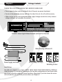
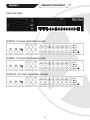
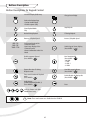
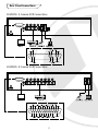
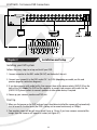
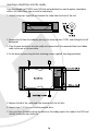
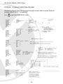
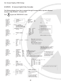
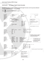
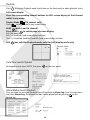
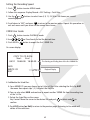
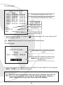
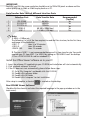
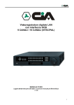
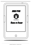
CCTV
EDVRCD4/8/16
Model:
Entry Level 4/8/16 Camera DVRs
with Integrated CD Writer
Introduction
The EDVRCD Entry Level DVR range is ideal for use as a direct replacement for an existing video
recorder and switcher, quad or multiplexer or as the heart of a new CCTV system. They are
competitively priced with features you would normally expect to see only on more expensive DVRs.
This includes superior picture quality, fast frame rates and an integrated CD Writer for easy backing up.
They are simple to install and use and are designed for use in low to medium risk applications.
Main Features
• Real Time Live Display of up to 16 cameras
• Real Time recording of up to 4 cameras on the EDVRCD4 and up to 100fps recording on the
EDVRCD8 & EDVRCD16
• Near DVD quality recording • 2 Camera audio recording
• Supports up to 2 hard drives for 1000GB recording capacity
• Duplex operation for multi screen recording & playback independently of live viewing selection
• Integrated CD Writer for easy backing of recordings to CD, which can be played back in any
compatible Windows PC
Model:
EDVRCD4/8/16
Entry Level 4/8/16 Camera DVRs
with Integrated CD Writer
Main Features in detail
Live Viewing Features
Full and Multi Screen Display: During live viewing on the EDVRCD4 (4 camera version) it is possible to view each
camera full screen or all 4 as a quad image, in addition to this on the EDVRCD8 (8 camera version) the cameras
can also be viewed as an 8 camera cameo, and on the EDVRCD16 (16 camera version) as a 16 camera cameo also.
Real Time Live Display: On all models the cameras are displayed in real time for smooth movement in all displays
views and at 720x 576 resolution for excellent quality when in full screen.
Audio: All models have 2 audio inputs which can be monitored live during live viewing.
Standard & VGA Monitor Support: All models have a standard BNC socket for video output to a Tv with Scart or AV
inputs or a CCTV monitor, and optional VGA output for connection to a PC monitor by adding the BNC2VGA adaptor.
Recording
Real Time Recording: The EDVRCD4 features real time recording at 360x288 resolution allowing it record in real
time. The EDVRCD8 and EDVRCD16 record at near real time with 100 fps shared between all cameras.
Near DVD Quality Recording: All models have a near DVD quality recording option which is 720x288 resolution
recording. In this mode they will record at 50fps shared between all cameras.
Wavelet Compression: The EDVRCD range uses the unique Xvision Wavelet+ compression codec for the highest
quality picture recording and lowest file size possible with wavelet compression. Up to 5 different recording
qualities and 6 different fps recording speeds can be set allowing the user to adjust the quality and speed to
achieve the best balance of recording time and picture quality.
Audio Recording: As well as camera images all models will also record up to 2 audio inputs.
Duplex Recording: The duplex recording feature of the EDVRCD range allows the user to select any camera full screen
or as a multiscreen layout during live viewing without disturbing the recording of all cameras as full screen images.
Continuous Recording: The standard recording mode of the range is continuous recording, in this mode the DVR
will record all the time.
Motion Detection Recording: The range also includes a motion detection recording feature, this allows areas of
each cameras view to be highlighted and then the DVR will only record when motion is detected in those areas.
Allowing the DVR to record for much longer than continuous recording would achieve.
Event Recording: The DVRs are fitted with alarm inputs for each camera input which will trigger recording of
cameras if the corresponding alarm input is triggered. Allowing the DVR to record for much longer than continuous
recording would achieve.
Timer Recording: The DVRs will allow the user to set up a comprehensive timer schedule so that it only records
during the times and days recording is required.
Recording Recycling: Once the hard drive is full the DVRs can be set to re-record over the hard drive or display a
message alerting the user that the hard drive is full.
Playback
Full and Multi Screen Playback: During playback on the EDVRCD4 (4 camera version) it is possible to view each
camera full screen or all 4 as a quad image, in addition to this on the EDVRCD8 (8 camera version) the cameras
can also be viewed as an 8 camera cameo, and on the EDVRCD16 (16 camera version) as a 16 camera cameo also.
Playback Speed Control: The playback speed can be reduced by 16x and increased by 16x for accurate control
during playback
Recording Search: Recordings can be quickly and easily found by simply entering the time and date the user is
looking for or by selecting from the motion or event recording lists, which list the time date and camera number that
was recorded.
2
Backing Up
Backup to CD: The EDVRCD range is fitted with a CD Writer for easy backing up on to a compatible Windows PC.
To back up the user simply inserts a CDR or CDRW and then selects the recording that needs to be backed up. The
unit then copies the recording requested and the Windows Playback Software on to the CD, this CD can then be
played back on any compatible Windows PC.
Networking/Internet Access
The EDVRCD range does not have networking/internet access, if you require these features please see the Xvision
TDVR Professional DVR range.
Recording Times: The following table shows an estimation of the recording space required to record for a day on all
the different fps and picture quality settings that can be selected. The GB shown are per day of recording time, to
calculate the time for a particular hard drive size that will be fitted in the DVR simply divide the Hard Drive size by
the GB shown on the table. (eg. For an 80Gb being recorded to at 25 fps in Best quality and at 720x288 resolution,
the calculation will be 80GB divided by 40GB which is 2 days)
Speed
Quality
1 fps
Low
4 fps
Good
Best
Low
12 fps
Good
Best
Low
25 fps
Good
Best
Low
Good
50 fps
Best
Low
Good
100 fps
Best
Low
Good
Best
Resolution 360 720 360 720 360 720 360 720 360 720 360 720 360 720 360 720 360 720 360 720 360 720 360 720 360 720 360 720 360 720 360 720 360 720 360 720
(x288)
GB per Day
(24 hours)
0.4
0.8
0.8
1.5
1.6
3.2
1.6
3.1
3.0
6.1
6.4 12.8 4.7
9.3
9.1 18.2 19.2 38.4 9.7 19.5 18.9 37.9 40.0 80.0 19.5 38.9 37.9 75.8 80.0 160.0 38.9 N/A 75.8 N/A 160.0 N/A
Index
Introduction
Page number
1
Main Features in detail
2
Chapter 1 - Package Contents
4
Chapter 2 - Controls & Connections
5
Front Panel
EDVR4CD - 4 Camera Digital Video Recorder
EDVR8CD - 8 Camera Digital Video Recorder
EDVR16CD - 16 Camera Digital Video Recorder
Buttons Description
Rear Panel
EDVR4CD - 4 Camera Digital Video Recorder
EDVR8CD - 8 Camera Digital Video Recorder
EDVR16CD - 16 Camera Digital Video Recorder
5
5
5
5
6
7
7
7
8
Chapter 3 - Installation and setup
8
Installing your DVR System
Start up
Hard Drive Space Check
Inserting a hard drive into the caddy
Hard Drive Guidelines
Initialising the Hard Drive
Onscreen display setup (OSD)
EDVR4CD - 4 Camera Digital Video Recorder
EDVR8CD - 8 Camera Digital Video Recorder
EDVR16CD - 16 Camera Digital Video Recorder
8
8
9
10
11
11
12
13
14
3
Chapter 4 - General Operations
Page number
15
Change Screen Display in Live mode
Motion Area Setup
REC Schedule Setup
Confirm Alarm Buzzer
Playback
Date/time Search Playback
Alarm/Motion Search Playback
Setting the recording speed
CDRW User Guide
15
15
15
15
16
16
16
17
17
Chapter5 - Video Output Methods
19
Offline Playback
(FAT32 Format Recording Only)
Recommended PC Requirement for offline
Viewer Software
Data Transfer rate Table of different
Interface Ports
Install the offline viewer software on to your PC
AVI Video Output
Printing Images
Images Zooming
Alarm Log
Date/Time Search Playback
20
20
21
22
23
23
23
Chapter 6 - FAQs
24
19
19
Chapter 1
Package Contents
THANK YOU FOR PURCHASING THIS EDVRCD SERIES DVR
• Please unpack the box carefully and identify that all the parts are present (see below).
• Do not cut the remove the warranty label from the side of the unit, this will void the warranty.
• Make sure you use only the recommended power supply. Damage caused to the unit by incorrect
voltage or wiring is not covered by the warranty.
EDVRCD Series Digital Video Recorder (4,8 and 16 Channel)
Video Viewing Software CD
Power Supply and Lead
Drive Caddy Lock Keys
Hard Drive
Retaining Screws
Hard Drives
This DVR unit is shipped with a choice of 80GB, 160GB, 250GB, 320GB, 500GB, 800GB or 1000GB of
Hard Drive space or no hard drive. Depending on the hard drive configuration you have chosen either
one or both of the drive caddys will contain hard drives. Alternatively, if you have chosen the version
with no hard drive, you can install your own drives. (see Chapter 4).
4
Chapter 2
Controls & Connections
Front Panel Detail
EDVR4CD- 4 Camera Digital Video Recorder
EDVR8CD- 8 Camera Digital Video Recorder
EDVR16CD- 16 Camera Digital Video Recorder
5
Buttons Description
Button Descriptions for Keypad Control
-On Screen Display (OSD) Setup
Change Screen Display
-Back to the Previous Page
- Back to Live/REC Mode
- Disable sequence (SEQ)
4ch 1-4
8ch 1-8
16ch 1-16
-Enter Playback Mode
-Play
Stop Playback
Rewind During Playback
FF During Playback
Decrease (-)Playback Speed
Increase (-)Playback Speed
-Full Screen Display of the
Selected Channel
-Spot Screen Display of the
Selected Channel
-Alarm Confirmation under Live
Mode
Switch Page of Screen Display
(Press MODE +
)
Enable sequence Channel
(Press MODE +
)
Nr of installed HDD
(Press MODE +
)
- No HDD
- 1 HDD
- 2 HDD 1
- 2 HDD2
Export video into CD during
Playback mode
Hard disk usage indicator
(Press MODE +
)
Time search Function in Playback
mode
(Press MODE +
)
Enable/Disable the display title
(Press MODE +
)
Audio Output
(Audio1/Audio2/Off/Audio1,2)
(Press MODE +
)
Enter
-OSD: Up Down Left Right
-Motion Area Setup
Note: These two buttons are disabled on the EDVRCD
6
Rear
Panel
Rear
Panel Connections
EDVR4CD- 4 Camera DVR Connections
EDVR8CD- 8 Camera DVR Connections
7
EDVR16CD- 16 Camera DVR Connections
Chapter 3
Installation and Setup
Installing your DVR system
Follows these easy steps to set up and install your DVR:
1. Connect a monitor to the BNC socket (M.OUT) on the back of the unit.
2. Connect your camera(s) to the BNC socket CH 1 to CH16 (depending on model, see this and
previous page for connection diagrams).
3. If you have cameras with audio facility, then connect them to the phono sockets (AUDIO IN) on the
back of the DVR. Note: This DVR has the capability to connect two cameras with audio. Use the
(AUDIO OUT) phono sockets to connect speakers or other audio device, if required.
4. Power up your cameras, monitor and DVR unit.
Start Up
1.When you first power up the DVR and you have a hard drive installed the camera will automatically
start to record to the hard drive (the DVR is factory set to record continuously at 100fps).
2. Your monitor screen will be split into a quad, 8-way or 16-way. If you have cameras connected the
images from the cameras will appear on screen (see Figure 4.1).
8
This diagram shows the camera titles, time/date positions and the way your screen will be split
(depending on whether you have a 4,8 or 16 channel model).
Figure 4.1
Hard Drive Space Check
Keypad Control: Press MODE, then press
bar as shown below:
; the DVR will then show the usage indication
The usage bar will
disappear after displaying
for several seconds
HDD USAGE
41%
9
Inserting a Hard Drive into the caddy
If you have bought an EDVRCD series DVR with no hard drive(s) or need to replace a hard drive
which is full follow these steps to install a hard drive(s):
1. Unlock (using keys supplied) and remove the caddy from the front of the unit.
2. Remove the lid from the caddy by pressing the release button ‘OPEN’ and sliding the lid off
backwards.
3. Place the new hard drive into the caddy and connect both the connector block and ribbon
cable to the rear of the new drive.
4. Fix the drive in place using the four retaining screws supplied (see diagram below).
5. Replace the lid of the caddy and slide forward until the lid locks.
6. Repeat steps 1-5 if you are installing another drive.
7. Once you have finished inserting the drive into the caddy, replace the caddy in the DVR and
lock by turning the key clockwise.
10
Hard Drive Guidelines
For trouble free operation of this DVR we recommend that you adhere to these guidelines when
choosing hard drives for the EDVRCD series:
• Use the same IDE protocol (e.g. ATA133) of Hard Drive (HDD)
• These drive sizes only must be used; Choose either 80/120/160 or 250Gb Hard Drive
Different IDE protocol is NOT supported (e.g. 1st Drive: ATA133, 2nd Drive: ATA???)
• Preferably use the same size Hard Drives for both (e.g. 1st Drive: Maxtor 160Gb ATA133, 2nd Drive:
Maxtor 160Gb ATA133) although different size drives are still compatible.
• Maxtor and Seagate Hard Drives are both compatible
with the EDVRDCD series.
This DVR does not support Western Digital Hard Drives.
Initialising the Hard Drives
Once you have either installed or replaced one or both hard drives in the drive caddy follow these
steps to initialise the hard drives:
Keypad Control: Press MODE, then press
.
If the password is required, insert the password and then press
.
If there is no password protection, press
when the message, ‘Please confirm to remote hard
drive’ is shown.
Note: Don’t remove the Hard Drive until ‘Remove HDD now’ message is shown. The
DVR will keep beeping with the message ‘Insert HDD now’ until you have inserted the
hard drive back in the DVR for recording.
REMOVE HDD NOW
AND PUSH ENTER BUTTON
The DVR will
keep beeping
after the Hard
Drive is
removed
INSERT HDD NOW
AND PUSH ENTER BUTTON
Insert a new hard drive press
you will hear a short beep which notifies that the hard
drive is activated and ready to record. If two hard drives are installed you will hear two beeps.
Note: If your ‘HDD Full’ under Display/Record is set to ‘STOP’, the message ‘HARD DISK
IS FULL’ will be shown on the screen and the DVR will stop recording until the Hard Drive
is replaced or inserted again.
11
On Screen Display (OSD) Setup
EDVR4CD- 4 Camera Digital Video Recorder
The following diagram shows how to navigate through the menus and set up more advanced
functions of the EDVR4CD - 4 Camera DVR.
Press
to go to the ‘MAIN MENU’ screen
12
On Screen Display (OSD) Setup
EDVR8CD- 8 Camera Digital Video Recorder
The following diagram shows how to navigate through the menus and set up more advanced
functions of the EDVR8CD - 8 Camera DVR.
Press
to go to the ‘MAIN MENU’ screen
13
On Screen Display (OSD) Setup
EDVR16CD- 16 Camera Digital Video Recorder
The following diagram explains how to navigate through the menus and set up more advanced
functions of the EDVR16CD - 16 Camera DVR.
Press
to go to the ‘MAIN MENU’ screen
14
Chapter 4
General Operations
Change Screen Display under Live Mode
Display Mode (
)
Press
once at a time to switch the screen display
4ch: Full/quad screen display selection
8ch: Quad/8-way screen display selection
16ch: Quad/8-way/16-way screen display selection
PAGE (
)
Press MODE+
to switch page of screen display
4ch: Not applicable
8ch: 1st Quad/2nd Quad screen display switching
16ch: Quad mode: 1st Quad/2nd Quad/3rd Quad/4th Quad screen display switching
8-way mode: 1st 8-way/2nd 8-way screen display switching
SEQ (
)
Press MODE+
to switch page of screen display
4ch: 1st Full > 2nd Full > 3rd Full > 4th Full > Quad > 1st Full....
8ch: 1st Full > 2nd Full > 3rd Full.... > 8th Full > 8-way > 1st Full....
16ch: 1st Full > 2nd Full > 3rd Full.... > 16th Full > 16-way > 1st Full....
Motion Area Setup
Select ‘Motion Area’ under the selected camera. The previous Motion Area will show on the
screen when you enter. Use
to move the cursor to the beginning point (upper
left) of your first detection zone, then press
for confirmation.
Move the cursor to the end (bottom right) point of the zone and press
for confirmation.
The cursor will then appear for you to set up your next zone. Repeat the process until you have
set up to four zones. Press to complete the motion setup (‘Motion set up OK’ will be shown
on the screen).
Adjust Alarm REC if your DVR is NOT in 24-hr REC Mode. Video Motion detection (VMD)
function will be enabled ONLY if the ‘Motion’ has been turned ON; and one detection zone
(minimum) has been set up.
REC Schedule Setup
Please make sure the REC Mode under Display/Record is in Schedule mode, and enter the
desired time into Setup REC Schedule under Others.
Confirm Alarm Buzzer
Once the alarm has been triggered, the screen will switch back to the original screen display.
Push the button with the corresponding channel number.
15
Playback
Press
to activate Playback mode. Use buttons on the front panel to adjust playback status.
Full screen display
Press the corresponding channel buttons for FULL screen display of that channel
whilst in any mode.
Display Mode
(16 channel only)
Press
to select Quad/16-way screen display
PAGE
(both 8 and 16 channel)
Press MODE+
to switch page of screen display
4ch: Not applicable
8ch: 1st Quad/2nd Quad screen display selection
16ch: 1st Quad/2nd Quad/3rd Quad/4th Quad screen display selection
SEQ
(not valid for Playback mode; valid for LIVE display mode only)
Date/Time Search Playback
For keypad control, press MODE, then press
on the front panel.
Alarm/Motion Search Playback
Once an alarm has occurred, the date/time will be saved to Alarm Log. Enter the main menu
on the
and select Alarm Log. The alarmed incident can be played back by pressing
desired log.
16
Setting the Recording Speed
1. Push
button to enter MENU mode.
2. Follow this sequence: Display/Record > REC Setting > Total Rate
3. Use the
or
recording speed.
buttons to select from 4, 8, 12, 25 50 or 100 frames per second
4. Scroll down to ‘EXIT’ and press
to return to the previous menu. Repeat this procedure to
exit each menu until you return to the camera view screen.
CDRW User Guide
1. Push
button to enter PLAYBACK mode.
2.Use
3. Push MODE+
or Time Search to find the desired time.
button to export the first 100MB File.
On screen display:
COPY TO CD ROM
Start
End
04/11 18:48:00 18:50:00
ADD
WRITE CD
EXIT
The Starting and Ending time of the first 100MB file
Playback Display
4. Add/delete the listed files:
A. For a 600MB CD you may choose up to 6 clips of files. After selecting the first clip, EXIT
the menu then repeat step 1,2,3 to select the 2nd file.
B. You can also select ADD and continue to export another 100MB file from the ending time
of the 1st file.
C. Delete the listed files on the screen:
Key Control: Move the cursor to the desired file and push
confirm.
to delete and
to
D. Push ESC button (or Exit) to return to the previous page. Returning to Live mode will
delete all the selections.
17
On screen display:
COPY TO CD
Start
04/11 18:48:00
04/12 13:00:00
04/12 13:01:20
04/13 15:11:00
04/13 15:12:11
04/13 15:13:13
ROM
End
18:50:00
13:01:20
13:02:10
15:12:11
15:13:13
15:14:45
ADD
WRITE CD
EXIT
The Starting and Ending time of the 1st file
The Starting and Ending time of the 2nd file
Continue exporting
another 100MB file
beginning from the end
time of the 1st file
Start to burn CD
Back to Playback Mode
5. Move the cursor to WRITE CD and push
minutes to burn a full CD.
to start burning the CD. It may take up to 20
Note: While burning the CD, the orange LED will keep flashing.
On screen display:
COPY TO CD ROM
Note: ESC button is disabled during the burn
function
DONE
04/11 18:48:00 18:50:00
Once the CD burning is completed, the DVR will show
a DONE message, eject your CD and return to
PLAYBACK mode
6. If you want to burn the same selected files to another CD, insert a blank CD first, then push
MODE + ENTER to start the burning process.
This DVR will automatically copy the player software onto the CD.
You can play back the CD on any PC using the player software
which supports multi-channel video and audio display
18
Chapter 5
Video Output methods
Offline Playback (FAT32- Format recording only)
Options to play back the recorded video file offline
1. Via IDE interface
Step1: Make sure the installed Hard Drive caddy is compatible with the following:
BT-27, BT-32, BT-42, RH-17, RH-27, RH-32, RH-42, MR-27 or L-007
Step2: Power of the PC before inserting the hard drive with drawer directly into the PC.
Step3: Power on the PC and run the supplied off line player to play back the recorded files.
Note: If your PC cannot recognise the Hard Drive, please change the hard disk jumper
configuration (Master only).
2. Via USB2.0/IDE convertor (optional item that can be purchased from your local
distributor)
Step1: Plug the USB2.0/IDE convertor in to the the IDE socket of the mobile drawer.
Step2: Connect the USB2.0 convertor to the PC with the USB2.0 cable.
Step3: Power on the USB2.0 convertor, then run the offline player.
Note: Please complete Step1 before powering on the USB2.0 convertor to prevent
unnecessary hard drive damage. Keep the jumper configuration of the hard drive in
‘Master’ mode.
Recommended PC requirement for offline viewer software
Your PC should have the following specifications to use the offline player software.
• CPU: Pentium3 1.0GHz or above • RAM: 256MB or above
• Hard Drive Space: 100MB or more
• Operating system: Windows ME and Windows 2000 with Microsoft DirectX 9.0 or later,
Windows XP with Microsoft DirectX 8.1 or later
19
IMPORTANT:
For NTSC and PAL the screen resolution should be set to 1024x758 pixels or above and the
colour quality set to 24bit or 32bit for play back on a PC.
Data Transfer Rate Table of different Interface Ports
1
2
3
4
5
Interface Port
Data Transfer Rate
IDE ATA66
IDE ATA100
IDE ATA133
USB2.0
USB1.1
66 MB/s
100MB/s
133MB/s
60 MB/s (480M bps)
1.5 MB/s (12M bps)
Recommended
(Yes/No)
Yes
Yes
Yes
Yes
No
Note:
1. MB/s = 8 Mbps etc.
The following is a list of the time required to read the files structure, for the first time,
and image to the hard drive:
-USB 1.1:
takes 5 to 10 minutes
-USB 2.0:
takes 30 seconds
-IDEATA 100:
takes 15 seconds
2. The use of USB1.1 is not recommended because of its slow transfer rate. You could
upgrade your PC from USB1.1 to USB2.0 by adding an ‘IDE/USB2.0 card’ for desktop
PCs or a PCMCIA/USB2.0 card for notebook PCs.
Install the Offline Viewer Software on to your PC
1. Insert the software CD supplied into your CD-ROM and installation will start automatically.
2. Click ‘playback software’ to install.
3. If the CD does not start automatically, please follow these steps:
3.1 Go to ‘My Computer’ and double click the CD-ROM.
3.2 Double click software folder.
3.3 Double click NR folder.
3.4 Double click ‘setup.exe’ to start installation.
After setup is complete, a shortcut
is created on the desktop.
Run OFFLINE Viewer Software
(Double click the shortcut and select the required language in the pop-up window or in the
main menu).
20
1. Click
to browse for folder shown.
2. Select the path to where the recorded files are located and click PLAY. (Recorded files should
be in the hard drive labeled TC-400_001).
3. Click OK.
4. Click
a loading dialogue box will appear on screen and the following USB
message will be displayed:
5. Playback screen will be shown after loading is completed. When an error occurs during
the loading process, the offline player will skip the error file and create
‘errfile.txt’ in the C drive.
AVI Video Output
After pressing the ‘AVI’ button, then choose the export file type from ‘Standard AVI’ or ‘Private
VDO’.
AVI Export Process:
- ’Select Camera No.’ will be shown when checking ‘Standard AVI’
- Choose the record time scale and then press ‘OK’.
21
- Play AVI files using Windows Media Player:
Note: Only Windows XP Media Player can adjust the playback speed.
Windows XP Media player speed settings: Click View > Enhancements > the click Play
Speed Settings (as below).
- Select ‘Private VDO’ export.
- Play the file and push ‘STOP AVI’ to start export.
- Click STOP AVI to start video export.
- Check to export offline player also.
Printing Images
- Make sure your computer has been connected to a working printer.
22
Image Zooming
- To zoom in or out on an image, select the image you require and the following will be
displayed:
Alarm Log
Date/Time Search Playback
23
Chapter 6
FAQs
Q:
A:
How long will it take to format the hard drive?
The DVR will support FAT32 recording automatically. You don’t have to partition the hard drive before
installing it in the DVR. It will take around 10 minutes for an 80GB hard drive, to prepare the FAT32
formatting, and about 20 minutes for a 160GB hard drive.
Q:
A:
How can I get a video clip from the EDVRCD?
Follow Chapter 5 to playback the recorded video and export it into a video clip using the offline viewer.
Q:
A:
What is V_Loss (Video Loss Alarm)?
V_Loss is the alarm mode that detects the connections of the cameras. The alarm will be activated in
any camera disconnects from the DVR.
Q:
Will my DVR record any motion that occurs during any other time than my REC
schedule?
Yes. Once your cameras are in ANY alarm mode, your DVR will automatically record any motion even if
it is not in the REC schedule.
A:
Q:
A:
How long will my DVR record for if the motion occurs during any other time than my
REC schedule?
The DVR will record the whole event and from1 to 60 seconds after the event occurred. The recording
time after the motion event can be adjusted in Alarm REC under Display/Record.
Q:
A:
Can I ‘Search Playback’ the recorded file via the index of Date/Time or Alarm Log?
Yes. You can easily play back the recorded video file by searching the index of date/time or alarm log
on the DVR or by using the offline player on your PC.
Q:
A:
Will my DVR keep recording during ‘Playback’ mode?
No. Note that once REC Resume is on, the system will automatically return to live record mode after 5
minutes of inaction during ‘Playback’ mode.
Q:
A:
What is the largest hard drive capacity the EDVRCD series can support?
The EDVRCD series can support all hard drives from Maxtor and Seagate with capacities from 40Gb up
to 250GB. Note: The EDVRCD series does not support ‘Western Digital’ hard drives.
Q:
Why does VMD (video motion detection) not work when I have set ‘Motion’ ON
already?
You have to set up at least one motion detection area in order to ENABLE the VMD function.
A:
TECHNICAL SUPPORT:
For Technical Support for any x-vision product please contact your local distributor.
LIMITED WARRANTY:
This product is supplied with a limited 1 Year warranty. The Warranty excludes products that have
been misused, (including accidental damage) and damage caused by normal wear and tear. In the
unlikely event that you encounter a problem with this product, it should be returned to the place of
purchase.
Manufactured exclusively for:
x-vision (Europe) Group,
Head Office: London, U.K.
Email: [email protected]
Web: www.x-vision.co.uk
24